1
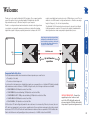
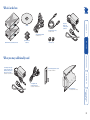
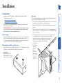
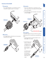
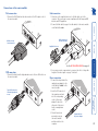
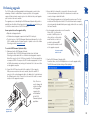
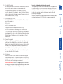
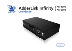
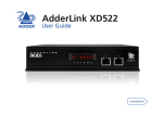
AdderLink X-DVI Digital video and USB extenders LI NK TO LO CA L ON E OT M RE ER ® D 2 3 4 AD 1 G ON UP Further information Troubleshooting.........................................................................11 Getting assistance.......................................................................11 Warranty.....................................................................................12 Safety information.....................................................................12 Radio Frequency Energy............................................................13 Connections..................................................................................4 Mounting the modules – desk or rack....................................4 Connections at the local module............................................5 Connections at the remote module........................................6 Video image compensation.........................................................7 Performing upgrades...................................................................8 Installation Operation....................................................................................10 General use............................................................................10 Video display (EDID) information.........................................10 Power and activity indicators................................................10 Important link cable advice.........................................................2 What’s in the box.........................................................................3 What you may additionally need................................................3 Operation F Welcome Contents modules can reliably transfer video rates up to 165Mpixels per second. This is in addition to two USB channels for keyboard and mouse - all via the same single length of Category 5, 5e or 6 twisted pair cabling. The AdderLink X-DVI extenders have been designed to be quick to install and totally transparent in operation. All connectors are industry standard and the video adjustments are made using simple keyboard button presses. REMOTE LOCAL CATx link cable ADDERLINK UPG LINK TO REMOTE POWER ADDER Ferrite core ON ® www.adder.com Up to 50 metres separation ADDERLINK LINK TO LOCAL POWER ADDER ON ® www.adder.com The actual maximum reliable video transmission distance depends upon several factors: • The quality of the cable, • The video resolution being used. For best results in the transmission of digital video signals we recommend the use of shielded CAT6 cable (preferably with a minimum conductor thickness of 26AWG). Using this cable, the following resolutions are achievable: • 1600x1200@60Hz (162Mpixels/second) at least 30m, • 1920x1200@60Hz, reduced blanking (154Mpixels/second) at least 30m, • 1920x1080@60Hz HDTV 1080p, reduced blanking (139Mpixels/second) at least 30m, • 1280x1024@60Hz (108Mpixels/second) at least 40m, • 1024x768@60Hz (65 Mpixels/second) at least 50m. CAT6 or better UTP cable will typically enable the above distances to be increased by 10 metres, however, the use of UTP cable is not guaranteed to meet emissions regulations at all screen resolutions and may be affected by external interference. CAT5 / CAT5e UTP cable will enable transmission distances that are equivalent to CAT6 shielded cable. Cables with thicker wires will generally give better performance (i.e. 24AWG is better than 26AWG). Important link cable advice Ferrite core VIDEO USB Proprietary pre-emphasis and equalisation techniques are used within the local and remote modules respectively to achieve the best possible video image at the monitor. See page 7 for further details. PC INSTALLATION ADVICE – Connect the supplied protective ferrites at each end of the CATx link cable and avoid disconnecting the CATx link cable whilst the product is operational (powered on). F Thank you for choosing the AdderLink X-DVI extenders. These compact modules present the quickest way to extend high quality DVI digital video plus USB keyboard and mouse up to 50 metres away from your computer. Thanks to our long involvement and investment in extender technology we have succeeded in overcoming the numerous problems associated with extending digital video signals. Using our proprietary transmission techniques the X-DVI Welcome What’s in the box LI TO ® NK 3 4 TO LO CA 20W power adapter and country- specific power lead CD-ROM L ON TE MO USB cable 2m (type A to B) Part number: VSC24 R ® ON 1 Eight self-adhesive rubber feet 3 4 AdderLink X-DVI local and remote modules Video cable DVI/D to DVI/D Part number: VSCD1 Two ferrite cores Power adapter and countryspecific power lead for local module (if powering via the USB port is not possible) Part number: PSU-IEC-5VDC-2.5A What you may additionally need Rack mount plate plus three screws Part number: X-RMK-X50 Serial upgrade cable 9-way D female to RJ-9 Part number: CAB-9DF-RJ9-2M Rack mount chassis Part number: X-RMK-CHASSIS F 2 A E DD 2 LI U PG ON R DE AD RE E OT 1 C ON LO NK R EM AL Installation Mounting the modules – desk or rack The X-DVI modules can be situated on a desk (or floor) or alternatively, for larger installations, mounted within an optional rack mount chassis. Desk mount Apply the supplied selfadhesive rubber feet to the underside of the module. UP G ® TO LI LO NK CA L ON Both modules have a block of four mini switches located on their side panels. All switches should remain OFF at all times during normal operation. Switch 1 on the remote module is used to place both modules into upgrade mode. All other switches are not used and should remain OFF at all times. Switch settings Rack mount Note: The module switches are not accessible once it is inserted into the rack, therefore, check all settings before insertion. 1 Place the rack securing plate (available as a separate kit) onto the front of the module and secure it with the two countersunk screws. 2 Orient the X-DVI module on its side so that its labelled face is the correct way up. 3 Slide the module into the required rack position. The rectangular cut-out in the front upper lip of the rack allows the two screws on the module’s upper edge to slide through. 4 The rack mount chassis has a series of holes in its floor that are spaced to accommodate the two screws on the module’s lower edge. Ensure that the screws correctly locate into the two holes of the chosen slot. The rack securing plate on the module should now be flush with the front of the rack mount chassis. 5 Use the third (pan-head) screw, in RE MO TE the top hole of the rack securing plate to fasten the module to the rack. AD DE R F Installation of the X-DVI modules is straightforward and requires minimal configuration in most cases. • Connections at the local module • Connections at the remote module Note: After all connections are made, power up the remote module first and then switch on the computer. INSTALLATION ADVICE – Connect the supplied protective ferrites at each end of the CATx link cable and avoid disconnecting the CATx link cable whilst the product is operational (powered on). Connections Connections at the local module Link connection 1 Attach one of the supplied ferrite cores to the link cable, next to the connector. This is necessary to ensure compliance with the European EMC directive and FCC regulations. 2 Connect the link cable (see page 2 for cable advice) to the local module socket labelled TO REMOTE. RE LI TE MO 1 Use the supplied DVI/D link cable to connect the DVI input socket of the local module to the digital video output socket of the computer. TO Video connection TO TE MO ON NK ON NK Supplied ferrite core See the INSTALLATION ADVICE on page 4 Power connection 1 Use the supplied USB cable to link the USB socket of the local module to a AL vacant USB socket on the computer. OC L Type-B connector of the USB link cable D AD The local module is designed to derive its power from the host computer via the USB connection. If this is not possible, then use an optional Adder power adapter. L 1 Connect the output lead of the optional power adapter Oto CA the socket L labelled ‘POWER‘ on the local module. 2 Insert the IEC connector of the separate power lead into the corresponding socket of the power adapter. Connect the other end of the power lead to a nearby mains socket. Note: After all connections are made, power up the remote module before, followed the local module, and then switch on the computer. D AD F USB connection RE LI RJ-45 connector of the CATx link cable DVI/D connector of the video link cable Output lead from the power adapter Connections at the remote module 1 Attach one of the supplied ferrite cores to the link cable, next to the connector. This is necessary to ensure compliance with the European EMC directive and FCC regulations. 2 Connect the link cable (see page 2 for cable advice) to the remote module socket labelled TO LOCAL. LI LO NK CA 1 Connect the DVI/D lead from the video monitor to the DVI output socket of the remote module. Link connection TO Video connection TO LI CA ON L ON Supplied ferrite core See the INSTALLATION ADVICE on page 4 1 Connect the leads from the keyboard and mouse to Othe TE two USB sockets on M RE the remote module. UP Type-A USB connectors from the keyboard and mouse G D AD 3 If necessary, use video compensation to overcome the effects of long cable lengths on the video signal - see page 7 for details. Power connection 1 Connect the output lead of the supplied power adapter to the socket labelled ‘POWER‘ on the remote module. 2 Insert the IEC connector of the separate power lead into the corresponding socket of the power adapter. Connect the other end of the power lead to a nearby mains socket. 3 After all connections are made, power up the remote module and then switch on the computer. TE MO RE UP G D AD F USB connection LO NK L RJ-45 connector of the CATx link cable DVI/D connector from the monitor Output lead from the power adapter To adjust the video image 1 Connect the X-DVI modules to the computer and peripherals as discussed earlier in this chapter. Power on the remote module and switch on the computer. 2 On the keyboard connected to the remote module, simultaneously press the and keys to enter Configuration mode - the three indicators on the keyboard should flash slowly in sequence. key to begin Compensation - the Scroll Lock indicator on the 3 Press the keyboard should flash. 4 Press the key to select the first compensation setting. Allow a few seconds to elapse in order to give time for the compensation mode to change and the video monitor time to adjust itself to the new signal. Note: In some cases the video image may disappear completely as the video monitor fails to decipher the signal. If this occurs, continue to follow these instructions until the best compensation setting is achieved. 5 If necessary, repeat step 4 using keys to , remembering to allow a few seconds after each press to allow the modules and video monitor to react. 6 When the best video image compensation is achieved, press the key to save the settings and return to the normal Configuration mode. The three indicators on the keyboard should once again flash slowly in sequence. 7 Press the key again to exit from the Configuration mode. F The X-DVI modules use a special two-part compensation technique to overcome the effects of long cable lengths upon the digital video signal. Under your control, the local and remote modules apply their own adjustments to the video signal. The local module applies Pre-emphasis to the video signal while the remote module uses Equalisation to return the signal to levels suitable for use at the connected DVI monitor. Using the keyboard connected to the remote module, you can choose from eight different video compensation settings (each setting affects both the local and remote modules) to achieve the best results. In certain cases there may be no image at the remote monitor until the appropriate compensation setting is chosen. Note: The effects of video compensation will only be noticeable on longer link cables lengths and/or higher video resolutions. Video image compensation The X-DVI modules are fully upgradeable via flash upgrades in order to take advantage of Adder’s continual drive to improve products. Such upgrades require a Windows-based computer system to be linked via the special upgrade port located on the remote module. The upgrade process is handled by the KVM Firmware Uploader utility, which is available from the Adder Technology website (www.adder.com) and allows you to check the current revision of the X-DVI modules. 3 - Ensure that the local module is connected to the remote module In the normal manner, check that the local and remote modules are connected using a suitable link cable. Note: During the upgrade process, both modules require power. The local module can either be powered via its USB socket from an active computer, or by using another standard Adder power supply, similar to the one used by the remote module. Items required to use the upgrade utility • Optional serial upgrade cable. • A Windows-based upgrade computer with an RS232 serial port. • The latest version of the KVM Firmware Uploader and firmware files for the X-DVI - available from the Technical Support > Updates section of the Adder Technology website (www.adder.com). 4 - Invoke upgrade mode and power on the modules Move switch 1 on the remote module to the ON position - all other switches on this module and all switches on the local module should remain OFF. Power up both modules as well as the upgrade computer. R D D E A ® 5 - Run the KVM Firmware Uploader utility From that folder, select the KVMUploader icon to run the upgrade utility. The KVM Firmware Uploader dialog will be displayed: 4 Optional serial upgrade cable 3 G F UP 2 2 - Connect the X-DVI remote module to the serial port of the computer With power removed from the remote module, attach the small RJ-11 connector of the optional upgrade cable to the UPG socket, located between the USB and power sockets. Connect the other end of the cable to a vacant TE serial port of the upgrade computer. MO RE Note: There is no need to change the serial port settings of the upgrade D AD computer, this will be handled by the KVM Firmware Uploader application. Set remote module switch 1 to ON ON 1 To use the KVM Firmware Uploader utility 1 - Obtain and run the KVM Firmware Uploader. Download the latest X-DVI KVM Firmware Uploader from the Adder Technology website and install it on a Windows-based upgrade computer that will be connected to the X-DVI remote module. The files are supplied as a compressed ZIP file. Decompress the ZIP file with an appropriate tool such as WinZip (www.winzip.com) and copy all contained files to the same folder on the upgrade computer. Performing upgrades 9 - Cycle the power Disconnect the power. Disconnect the remote module from the upgrade computer and return switch 1 on the remote module to its OFF position. Reconnect the modules in their normal manner. When the power is re-applied the X-DVI modules will operate using the new firmware. INSTALLATION ADVICE – Connect the supplied protective ferrites at each end of the CATx link cable and avoid disconnecting the CATx link cable whilst the product is operational (powered on). 8 - Commence the upgrade To begin the upgrade process, click the Upload Now button. The progress will be shown within the dialog. Should you decide not to continue with the upload at any stage, click the Abort button; response to this is usually immediate, however, during an erase command, the upload will not be aborted until the erase is complete (this may take a few seconds). The remote module will upgrade its own firmware and also pass upgrade code via the link cable to the local module. 7 - Select the upgrade file to be used From the main KVM Firmware Uploader dialog, click the Browse... button and select the upgrade file: X-DVI_x.xx.txt where x.xx is the firmware version. The upgrade file details will be displayed within the dialog. IMPORTANT: Check that the ‘Intended Target Units’ field matches the ‘Unit Connected’ field. If these fields do not match then you may have an incorrect upgrade file, check with Adder Technology Ltd before proceeding. Check also that the ‘New firmware version’ is greater than the ‘Current firmware version’. Issues to consider when performing flash upgrades The upgrade program rewrites the X-DVI firmware code. If the upgrade process is interrupted then the X-DVI modules will have invalid code and will not be able to operate. It is therefore good practice to ensure that the upgrade process is always fully completed. A partial or failed upgrade may be rectified by performing another upgrade. WARNING: Running faulty or partially upgraded code may have unpredictable results and may damage your X-DVI modules or computing equipment. F 6 - Query the X-DVI modules Click the Query Unit button to confirm that communication is possible with the X-DVI modules and to establish the existing firmware details. If the application cannot contact the X-DVI modules, re-check the connection cable and click the Advanced... button to check that the correct serial port is being used on the upgrade computer. Change the serial port within the Advanced section, if necessary. Operation Power and activity indicators Each module provides two indicators to confirm power status and also feedback about the various input signals: TE MO ON NK Yellow: • On when a valid DVI video input signal is being received from the local module. Flashes regularly (twice per second) when no valid DVI video signal is being received from the local module. •Blinks in response to inputs from the keyboard/mouse. F Green: • On when power is present. operation Remote module TO LI LO NK CA ON L Extended Display Identification Data (or EDID) is an industry standard scheme which allows video monitors to declare their capabilities to the computer’s video adapter circuitry, allowing the latter to optimise their outputs accordingly. Since the widespread adoption of the scheme, video adapters have become increasingly dependent on receiving relevant EDID information during startup, before they will output anything more than a rudimentary video signal. Each time that the remote module is powered on, it attempts to read the EDID information from the connected DVI video monitor. If the attempt is sucessful, the information is transferred to the local module and stored within non-voltile memory. This is information is then made available to the computer’s video adapter when required. Yellow: • On when a valid DVI video input signal is being received from the computer. Flashes regularly (twice per second) when no valid DVI video signal is being received from the computer. • Off when the CATx link cable is disconnected. •Blinks in response to inputs from the remote keyboard/ mouse. RE Video display (EDID) information Green: • On when power is present. Local module LI In use, the X-DVI modules should be transparent - the system and its peripherals should operate exactly as normal, the only difference being that they are now up to 50 metres apart. In some installations, you may see some small flickering of pixels on the screen, particularly at higher screen resolutions. This is due to some portions of the video data being misinterpreted by the video monitor. Assuming that the video monitor is working correctly, this condition is generally caused by a combination of the screen resolution and the length/quality of the link cable. In certain cases, the data misinterpretation can lead to a complete loss of the video image. If any of the above conditions occur, your first step should be to use the in-built X-DVI video compensation feature to alleviate the situation. See Video image compensation for details. TO General use Operation 10 Further information The video image is showing some small flickering of the pixels • The combination of cable length and screen resolution may be causing data errors that the video monitor cannot currently resolve. Try adjusting the video compensation setting. See Video image compensation for details. • Email – [email protected] • Fax in the UK: in the US: 01954 780081 +1 888 275 1117 • Phone in the UK: in the US: 01954 780044 +1 888 275 3337 • Adder Technology website – www.adder.com Check the Support section of our website for the latest solutions and driver files. No video image is displayed on the remote monitor • Check the yellow indicators on the local and remote modules while no keys are pressed on the keyboard and no mouse movements are being made both indicators should be continually on when a valid video signal is present. LOCAL: If the yellow indicator is giving a regular flash (twice per second), then the video feed to the local module is not valid. Try connecting a DVI monitor (preferably using the same DVI link cable as used with the local module) directly to the computer and check for a correct image. REMOTE: If the yellow indicator is giving a regular flash (twice per second), then the video feed via the link cable is not valid. If the link cable is long, try using a short link cable temporarily to check for basic operation. If the yellow indicators are off, then the link cable is not properly connected. • Once you have verified that a valid video signal is present at the remote module, try adjusting the video compensation setting. See Video image compensation for details. If you are still experiencing problems after checking the list of solutions in the Troubleshooting section then we provide a number of other solutions: If you experience problems when installing or using the X-DVI modules, please check through this section for a possible solution. If your problem is not listed here and you cannot resolve the issue, then please refer to the ‘Getting assistance’ section. Getting assistance Troubleshooting 11 • For use in dry, oil free indoor environments only. • Do not use to link between buildings. • Ensure that the twisted pair interconnect cable is installed in compliance with all applicable wiring regulations. • Do not connect the CATx link interface (RJ45 style connector) to any other equipment, particularly network or telecommunications equipment. • Warning – the power adapter contains live parts. • No user serviceable parts are contained within the power adapter - do not dismantle. • Plug the power adapter into a socket outlet close to the unit that it is powering. • Replace the power adapter with a manufacturer approved type only. • Do not use the power adapter if the power adapter case becomes damaged, cracked or broken or if you suspect that it is not operating properly. • If you use a power extension cord with the units, make sure the total ampere rating of the devices plugged into the extension cord do not exceed the cord’s ampere rating. Also, make sure that the total ampere rating of all the devices plugged into the wall outlet does not exceed the wall outlet’s ampere rating. • Do not attempt to service the units yourself. • The units and power supplies can get warm in operation – do not situate them in an enclosed space without any ventilation. • The units do not provide ground isolation and should not be used for any applications that require ground isolation or galvanic isolation. Adder Technology Ltd warrants that this product shall be free from defects in workmanship and materials for a period of two years from the date of original purchase. If the product should fail to operate correctly in normal use during the warranty period, Adder will replace or repair it free of charge. No liability can be accepted for damage due to misuse or circumstances outside Adder’s control. Also Adder will not be responsible for any loss, damage or injury arising directly or indirectly from the use of this product. Adder’s total liability under the terms of this warranty shall in all circumstances be limited to the replacement value of this product. If any difficulty is experienced in the installation or use of this product that you are unable to resolve, please contact your supplier. Safety information Warranty 12 Canadian Department of Communications RFI statement This equipment does not exceed the class A limits for radio noise emissions from digital apparatus set out in the radio interference regulations of the Canadian Department of Communications. Le présent appareil numérique n’émet pas de bruits radioélectriques dépassant les limites applicables aux appareils numériques de la classe A prescrites dans le règlement sur le brouillage radioélectriques publié par le ministère des Communications du Canada. This equipment generates, uses and can radiate radio frequency energy and if not installed and used properly, that is, in strict accordance with the manufacturer’s instructions, may cause interference to radio communication. It has been tested and found to comply with the limits for a class A computing device in accordance with the specifications in Subpart J of part 15 of FCC rules, which are designed to provide reasonable protection against such interference when the equipment is operated in a commercial environment. Operation of this equipment in a residential area may cause interference, in which case the user at his own expense will be required to take whatever measures may be necessary to correct the interference. Changes or modifications not expressly approved by the manufacturer could void the user’s authority to operate the equipment. This equipment has been tested and found to comply with the limits for a class A computing device in accordance with the specifications in the European standard EN55022. These limits are designed to provide reasonable protection against harmful interference. This equipment generates, uses and can radiate radio frequency energy and if not installed and used in accordance with the instructions may cause harmful interference to radio or television reception. However, there is no guarantee that harmful interference will not occur in a particular installation. If this equipment does cause interference to radio or television reception, which can be determined by turning the equipment on and off, the user is encouraged to correct the interference with one or more of the following measures: (a) Reorient or relocate the receiving antenna. (b) Increase the separation between the equipment and the receiver. (c) Connect the equipment to an outlet on a circuit different from that to which the receiver is connected. (d) Consult the supplier or an experienced radio/TV technician for help. FCC Compliance Statement (United States) European EMC directive 89/336/EEC A Category 5 (or better) shielded twisted pair cable must be used to connect the local and remote units in order to maintain compliance with radio frequency energy emission regulations and ensure a suitably high level of immunity to electromagnetic disturbances. All other interface cables used with this equipment must be shielded in order to maintain compliance with radio frequency energy emission regulations and ensure a suitably high level of immunity to electromagnetic disturbances. Radio Frequency Energy 13 Tel: +65 6288 5767 Fax: +65 6284 1150 Adder Asia Pacific 6 New Industrial Road, Hoe Huat Industrial Building #07-01, Singapore 536199 Adder Corporation, 29 Water Street, Newburyport, MA 01950, United States of America Tel: +1-888-932-3337 Fax: +1-888-275-1117 Adder Technology Limited, Technology House, Trafalgar Way, Bar Hill, Cambridge, CB23 8SQ, United Kingdom Tel: +44 (0)1954 780044 Fax: +44 (0)1954 780081 © 2008 Adder Technology Limited All trademarks are acknowledged. Release 1.0f December 2008 Part No. MAN-X-DVI Documentation by: www.ctxd.com 14