1
SERVICE MANUAL
SERVICE MANUAL
CREDITS/COPYRIGHT
©
1996–99, 2001 Best Lock Corporation. All rights reserved. Printed in the United
States of America.
Information in this document is subject to change without notice and does not
represent a commitment on the part of Best Lock Corporation. The software described
in this document are furnished under a license agreement or nondisclosure agreement.
This publication is intended to be an accurate description and set of instructions
pertaining to its subject matter. However, as with any publication of this complexity,
errors or omissions are possible. Please call your Best Lock distributor or Best Lock
Corporation at (317) 849-2250 if you see any errors or have any questions. No part of
this manual and/or databases may be reproduced or transmitted in any form or by any
means, electronic or mechanical, including photocopying, recording, or information
storage and retrieval systems, for any purpose, without the express written permission
of Best Lock Corporation.
This document is distributed as is, without warranty of any kind, either express or
implied, respecting the contents of this book, including but not limited to implied
warranties for the publication’s quality, performance, merchantability, or fitness for any
particular purpose. Neither Best Lock Corporation, nor its dealers or distributors shall
be liable to the user or any other person or entity with respect to any liability, loss, or
damage caused or alleged to be caused directly or indirectly by this publication.
Written and designed at Best Lock Corporation, 6161 East 75th Street, Indianapolis,
Indiana 46250
T61932 Rev C 17778112 April 2001
CONTENTS
FIGURES V
GETTING STARTED
Introduction
1–7
1–7
Certifications and standards 1–7
HV and KV Locks 1–7
V Series Controller 1–8
Documentation package
1–8
Technical support 1–9
Support services 1–9
Telephone technical support
Training seminars 1–10
SECURITY DEVICE MAINTENANCE
1–9
2–1
8KV/9KV magnetic stripe trim exploded diagram 2–2
8KV/9KV magnetic stripe trim parts list 2–3
8KV/9KV keypad trim exploded diagram 2–4
8KV/9KV keypad trim parts list 2–5
8KV/9KV proximity trim exploded diagram 2–6
8KV/9KV proximity trim parts list 2–7
8KV/9KV exploded chassis diagram 2–8
8KV/9KV chassis parts list 2–9
34/35HV magnetic stripe trim exploded diagram 2–10
34/35HV magnetic stripe trim parts list 2–11
34/35HV keypad trim exploded diagram 2–13
34/35HV keypad trim parts list 2–14
V Series Service Manual
i
Contents
34/35HV proximity trim exploded diagram 2–16
34/35HV proximity trim parts list 2–17
34/35HV case with deadbolt exploded diagram 2–19
34/35HV case with deadbolt parts list 2–20
34/35HV case without deadbolt exploded diagram 2–21
34/35HV case without deadbolt parts list 2–22
XV Controller exploded diagram 2–23
XV Controller parts list 2–23
External communications exploded diagram 2–24
External communications parts list 2–24
Programming parts diagram 2–25
Programming parts list 2–25
Card encoder parts diagram 2–26
Card Encoder parts list 2–26
Lock external power supply parts diagram 2–26
Lock external power supply parts list 2–26
Special tools diagram 2–27
Special tools parts list 2–27
Function descriptions 2–28
HV Locks 2–28
KV Lock 2–29
Function conversion
2–30
34HV/35HV knob/lever conversion
2–31
Reader conversion 2–32
HV reader conversion 2–32
KV reader conversion 2–34
Replacing parts 2–36
Replacing batteries 2–36
Removing and reinstalling the inside and outside trim
Replacing the wire harnesses 2–39
Replacing the inside circuit board 2–42
Replacing the card reader or keypad reader 2–42
Replacing the PROM 2–44
TROUBLESHOOTING
2–38
3–1
Emergency operations 3–1
How do you enable communications if you have lost the token or forgotten
the password? 3–1
How do you open a lock after a complete battery failure? 3–2
Troubleshooting the V Series Electronic Lock
3–4
Troubleshooting the V Series Controller 3–7
For readers with red and green LEDs and no sounder 3–7
For readers with a dual red/green LED and sounder 3–9
ii
V Series Service Manual
Contents
Alarm troubleshooting
GLOSSARY
3–11
A–1
SECURITY DEVICE HISTORY EVENT TYPES
INSTALLATION INSTRUCTIONS
INDEX
V Series Service Manual
B–1
C–1
D–1
iii
Contents
iv
V Series Service Manual
FIGURES
SECURITY DEVICE MAINTENANCE
8KV/9KV magnetic stripe trim exploded diagram
8KV, 9KV keypad trim exploded diagram
2–4
8KV/9KV proximity trim exploded diagram
8KV/9KV chassis exploded diagram
2–2
2–6
2–8
34/35HV magnetic stripe trim exploded diagram
34/35HV keypad trim exploded diagram
2–10
2–13
34/35HV proximity trim exploded diagram
2–16
34/35HV case with deadbolt exploded diagram
2–19
34/35HV case without deadbolt exploded diagram
XV controller exploded diagram
2–23
External communications exploded diagram
Programming parts
2–25
Card Encoder parts
2–26
Lock external power supply parts
Special tools
2–21
2–24
2–26
2–27
Removing and replacing the battery compartment cover
Disconnecting the old battery pack
Removing the inside trim
2–37
2–37
2–38
Orienting the communication port
2–41
Prying one corner of the PROM part way out of the socket
[V Series electronic lock shown] 2–45
Prying the opposite corner of the PROM
Inserting the new PROM
V Series Service Manual
2–45
2–46
v
Figures
TROUBLESHOOTING
Enabling communications using the DIP switches
3–2
Connecting the palmtop cable to the base of the lock
vi
3–3
V Series Service Manual
1
GETTING STARTED
INTRODUCTION
The V Series Service Manual contains essential
information to help you maintain your 8KV, 9KV,
30HV stand-alone locks, and the XV Controller.
CERTIFICATIONS AND STANDARDS
HV and KV
Locks
■
■
■
V Series Service Manual
The strike fits the standard door frame cutout as
specified in ANSI A115.1.
The faceplate dimensions fit the standard door
preparation as specified in ANSI A115.1.
The locks comply with the following:
▲ FCC CFR 47 Part 15, Subpart C for Intentional
Radiators
▲ CES–003 Canadian EMI Requirements
▲ IEC 61000–4–2 (1995) ESD Immunity
▲ IEC 61000–4–3 (1995) RD Immunity
▲ IEC 61000–4–4 (1995) EFT Immunity
▲ International Safe Transit Association–
Procedure 1A
▲ Humidity Test RTCA/DO–160C–Extended
Humidity.
1–7
Getting Started
V Series
Controller
The controller complies with the following:
■
■
■
■
■
■
■
FCC CFR 47 Part 15, Subpart C for Intentional Radiators
CES–003 Canadian EMI Requirements
IEC 61000–4–2 (1995) ESD Immunity
IEC 61000–4–3 (1995) RD Immunity
IEC 61000–4–4 (1995) EFT Immunity
International Safe Transit Association–Procedure 1A
Humidity Test RTCA/DO–160C–Extended Humidity.
DOCUMENTATION PACKAGE
The following documentation is available to help you with the
installation, start-up, and maintenance of the V Series System. To order a
document, contact your BEST representative.
The installation instructions for the locks and controller also can be
ordered separately:
Document Title
Doc. No.
8KV/9KV Installation Instructions
T61918
30HV Installation Instructions
T61919
XV Controller Installation Instructions
T61920
The templates required for lock installations also can be ordered
separately:
1–8
Document Title
Doc. No.
Installation Template for 83KV/93KV Locksets
T61921
Installation Template for 34HV–35HV Locksets
T61922
Installation Specifications for 34HV–35HV
Locks/Hole Pattern Chart for 34HV–35HV Locks
T61923
V Series Controller Drilling Template
T61924
V Series Service Manual
Getting Started
The wiring and power related instructions can be ordered separately:
Document Title
Doc. No.
V Series Controller Wiring Diagram
T61928
External Power Installation Instructions
T61925
Door Wiring Instructions for Electrically–Operated T61926
Locksets
Depending on the programming method you choose for the V Series
System, you may need one or more of the following manuals:
Document Title
Doc. No.
V Series Handheld Terminal User Manual
T61931
V Series Intelligent Programmer Software
User Manual
T61930
IPS Getting Started Instructions
T61929
Depending on the type of reader you choose for the V Series System,
you may need one or more of the following manuals:
Document Title
Doc. No.
Installation Instructions for the BEST Encoder
T61933
V Series Keypad Security Device Programming
Guide
T61927
V Series Keypad Security Device
Quick Programming Guide
T61938
TECHNICAL SUPPORT
Support
services
When you have a problem with the V Series Lockset, your first resource
for help is the V Series Service Manual. If you cannot find a satisfactory
answer, contact your local BEST representative.
Telephone
technical
support
A factory-trained Certified Product Specialist (CPS) is available in your
area whenever you need help. Before you call, however, please make
sure you are at the location where the problem exists, and that you are
prepared to give the following information:
■
■
■
■
V Series Service Manual
the exact wording of any error or warning messages
what happened and what you were doing when you encountered
the problem
what you have done so far to correct the problem
the lock serial number located on the inside trim in the battery
compartment.
1–9
Getting Started
Best Access Systems Representatives provide telephone technical
support for all V Series products. You may locate the representative
nearest you by calling (317) 849-2250 Monday through Friday, between
7:00 a.m. and 4:00 p.m. eastern standard time; or visit the web page,
www.BestAccess.com.
Training
seminars
1–10
BEST holds training sessions for its customers. If you are interested, you
may contact your local BEST representative for the details.
V Series Service Manual
2
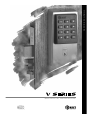
SECURITY DEVICE
MAINTENANCE
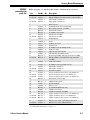
The following pages contain exploded diagrams for
all V Series Security Devices. These diagrams detail
all field serviceable mechanical and electronic parts.
Use the diagrams and parts lists on the following
pages to find the part numbers you need.
V Series Service Manual
2–1
15
13
11
19
17
21
11
9
7
24
5
23
1
3
1
20
3
14
V Series Service Manual
12
10
4
2
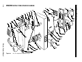
Figure 2.1
8KV/9KV magnetic stripe trim exploded diagram
6
8
16
18
22
Security Device Maintenance
2–2
8KV/9KV MAGNETIC STRIPE TRIM EXPLODED DIAGRAM
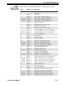
Security Device Maintenance
8KV/9KV
magnetic stripe
trim parts list
Refer to Figure 2.1 and the table below to find the part you need.
Item
Part No. Qty.
1a
Description
2
Knob or lever
2
C61403
1
9KV outside escutcheon
not shown
C61405
1
8KV outside escutcheon
3
A61503
2
Wire clamp (1 inside, 1 outside)
4
A61502
1
Communications port retainer clip
5
B61646
1
Card reader
6
A61643
1
Outside wire harness for card reader
A61429
2
Card reader screws
D60464
1
9KV chassis assembly
not shown
D60419
1
8KV chassis assembly
9
B61649
1
Outside wire harness clip
10
C54680
1
Latch
11
A61433
2
Plastic bushings
12
A25359
2
Latch screws
13
B62099
1
Programmed PROM (VP_S15)
14
C55556
1
Inside rose liner
15
A61501
4
Circuit board screws
16
A55557
2
Through–bolt mounting screws
17
B61664
1
Circuit board (without PROM)
18
A61642
1
Inside wire harness
19
B61412
1
Upper escutcheon screw for 1 3/4″ thick doors
not shown
B61413
1
Upper escutcheon screw or 2″ thick doors
not shown
B61414
1
Upper escutcheon screw for 2 1/4″ thick doors
20
C61404
1
9KV inside escutcheon
not shown
C61406
1
8KV inside escutcheon
21
C61410
1
Battery cover
22
A61422
1
Lower escutcheon screw for 1 3/4″ thick doors
not shown
A61423
1
Lower escutcheon screw or 2″ thick doors
not shown
A61424
1
Lower escutcheon screw for 2 1/4″ thick doors
23
B61917
1
Alkaline battery pack
24
A61411
1
Battery cover screw (torx with post head) or
A61428
1
Battery cover screw (McGard head)
7
8
b
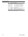
a. Refer to the H Series Service Manual for knob and lever part numbers.
b. For 8KV/9KV chassis parts, see Figure 2.4.
V Series Service Manual
2–3
28
11
15
13
17
19
21
23
29
31
30
27
25
25
26
24
9
7
3
1
5
1
22
1
20
5
18
16
14
V Series Service Manual
12
6
4
2
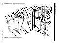
Figure 2.2
8KV, 9KV keypad trim exploded diagram
8
10
3
Security Device Maintenance
2–4
8KV/9KV KEYPAD TRIM EXPLODED DIAGRAM
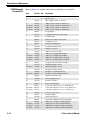
Security Device Maintenance
8KV/9KV
keypad trim
parts list
Refer to Figure 2.2 and the table below to find the part you need.
Item
Part No. Qty.
Description
1
B60325
1
Keypad assembly with cable and connector
2
not shown
C60449
C60448
1
1
9KV outside escutcheon
8KV outside escutcheon
2
Knob or lever
3a
4
A61502
1
Communications port retainer clip
5
A61503
2
Wire clamp (1 inside, 1 outside)
6
B60305
1
Outside wire harness for keypad
7
B60321
1
Keypad gasket
8b
not shown
D60464
D60419
1
1
9KV chassis assembly
8KV chassis assembly
9
A60318
2
Retaining rings
10
C54680
1
Latch
11
A60317
2
Sealing lens covers
12
A25359
2
Latch screws
13
A60348
4
Keypad mounting screws
14
C55556
1
Inside rose liner
15
A60324
1
Adhesive tape for sounder
16
A55557
2
Through–bolt mounting screws
17
C60303
1
Keypad reader electronics assembly
18
A61642
1
Inside wire harness
19
A61429
2
Keypad electronics screws
20
not shown
C61404
C61406
1
1
9KV inside escutcheon
8KV inside escutcheon
21
A60316
1
Escutcheon gasket
22
not shown
not shown
A61422
A61423
A61424
1
1
1
Lower escutcheon screw for 1 3/4″ thick doors
Lower escutcheon screw or 2″ thick doors
Lower escutcheon screw for 2 1/4″ thick doors
23
B61649
1
Outside wire harness clip
24
B61917
1
Alkaline battery pack
25
A61433
2
Plastic bushings
26
C61410
1
Battery cover
27
B62076
1
Programmed PROM for keypad (VP15KP)
28
A61501
4
Circuit board screws
29
B61664
1
Circuit board (without PROM)
30
not shown
not shown
B61412
B61413
B61414
1
1
1
Upper escutcheon screw for 1 3/4″ thick doors
Upper escutcheon screw or 2″ thick doors
Upper escutcheon screw for 2 1/4″ thick doors
31
not shown
A61411
A61428
1
1
Battery cover screw (torx with post head) or
Battery cover screw (McGard head)
a. Refer to the H Series Service Manual for knob and lever part numbers.
b. For 8KV/9KV chassis parts, see Figure 2.4.
V Series Service Manual
2–5
28
29
17
11
19
25
21 23
31
31
27
25
15
13
26
9
7
1
3
24
5
3
22
20
5
18
16
14
V Series Service Manual
12
6
4
2
Figure 2.3
8KV/9KV proximity trim exploded diagram
8
10
Security Device Maintenance
2–6
8KV/9KV PROXIMITY TRIM EXPLODED DIAGRAM
Security Device Maintenance
8KV/9KV
proximity trim
parts list
Refer to Figure 2.3 and the table below to find the part you need.
Item
Part No. Qty.
Description
1
not shown
2
not shown
3a
4
5
6
7
8b
not shown
9
10
11
12
13
14
15
16
17
not shown
C60337
C60342
C60449
C60448
A61502
A61503
B60305
B60321
D60464
D60419
A60318
C54680
A60317
A25359
A60348
C55556
A60324
A55557
B60338
B60339
1
1
1
1
2
1
2
1
1
1
1
2
1
2
2
4
1
1
2
1
1
18
19
20
not shown
21
22
not shown
not shown
23
24
25
26
27
28
29
30
not shown
not shown
31
not shown
A61642
A61429
C61404
C61406
A60316
A61422
A61423
A61424
B61649
B61917
A61433
C61410
B62099
A61501
B61664
B61412
B61413
B61414
A61411
A61428
1
2
1
1
1
1
1
1
1
1
2
1
1
4
1
1
1
1
1
1
Motorola proximity bezel with reader assembly
HID proximity bezel with antennae & IR assembly
9KV outside escutcheon
8KV outside escutcheon
Knob or lever
Communications port retainer clip
Wire clamp (1 inside, 1 outside)
Outside wire harness
Proximity reader gasket
9KV chassis assembly
8KV chassis assembly
Retaining rings
Latch
Sealing lens covers
Latch screws
Proximity reader mounting screws
Inside rose liner
Adhesive tape for sounder
Through–bolt mounting screws
Motorola proximity wake-up electronics assembly
HID proximity reader with wake--up electronics
assembly
Inside wire harness
Proximity reader electronics screws
9KV inside escutcheon
8KV inside escutcheon
Escutcheon gasket
Lower escutcheon screw for 1 3/4″ thick doors
Lower escutcheon screw or 2″ thick doors
Lower escutcheon screw for 2 1/4″ thick doors
Outside wire harness clip
Alkaline battery pack
Plastic bushings
Battery cover
Programmed PROM (VP_S15)
Circuit board screws
Circuit board (without PROM)
Upper escutcheon screw for 1 3/4″ thick doors
Upper escutcheon screw or 2″ thick doors
Upper escutcheon screw for 2 1/4″ thick doors
Battery cover screw (torx with post head) or
Battery cover screw (McGard head)
a. Refer to the H Series Service Manual for knob and lever part numbers.
b. For 8KV/9KV chassis parts, see Figure 2.4.
V Series Service Manual
2–7
Security Device Maintenance
2–8
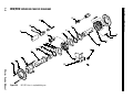
8KV/9KV EXPLODED CHASSIS DIAGRAM
11
21
20
10
6
19
9
8
18
17
16
7
8
15
6
5
14
4
3
13
2
1
V Series Service Manual
Figure 2.4
12
8KV/9KV chassis exploded diagram
Security Device Maintenance
8KV/9KV
chassis parts
list
V Series Service Manual
Refer to Figure 2.4 and the table below to find the part you need.
Item
Part No. Qty.
Description
1
A55557
2
Through–bolt mounting screws
2
C55556
1
Inside rose liner
3
A55685
1
Inside hub assembly
4
B60418
1
Non-keyed sleeve assembly for 8KV
not shown
B55610
1
Non-keyed sleeve assembly for 9KV
5
A55517
1
Spring guide
6
B55518
2
Lever return springs for 9KV
not shown
B60420
1
Lever return spring for 8KV (outside only)
7
B60470
1
Wire protection cap
8
B55504
2
Thrust plates
9
A60461
1
Key release cam assembly
10
C55515
1
Spring drive plate
11
A54200
1
Throw member
12
C54680
1
Latch
13
B60416
1
Chassis frame and retractor assembly for 8KV
not shown
B60463
1
Chassis frame and retractor assembly for 9KV
14
A25359
1
Latch screw
15
A55687
1
Keyed sleeve assembly
16
D55571
1
Outside hub
17
A55505
2
Chassis screws
18
A55603
1
Outside liner and stud assembly
19
C60473
1
Motor mount
20
A61012
1
Motor
21
B60520
1
Spindle and plunger sub assembly
2–9
5
1
7
9
11
11
13
15
17
19
3
28
27
26
2
25
21
22
23
1
24
20
18
16
V Series Service Manual
10
8
6
4
2
Figure 2.5
34/35HV magnetic stripe trim exploded diagram
14
12
Security Device Maintenance
2–10
34/35HV MAGNETIC STRIPE TRIM EXPLODED DIAGRAM
Security Device Maintenance
34/35HV
magnetic stripe
trim parts list
Refer to Figure 2.5 and the table below to find the part you need.
Item
Part No. Qty.
Description
1
A61503
2
Wire clamp (1 inside, 1 outside)
2
Knob or lever
2a
3
B61646
1
Card reader
4
not shown
not shown
not shown
C61400
C61402
C61420
C61405
1
1
1
1
35HV outside escutcheon with key or
35HV outside escutcheon without key or
34HV outside escutcheon with key or
34HV outside escutcheon without key
5
A61429
2
Card reader screws
6
A61502
1
Communications port retainer clip
7
B61649
1
Outside wire harness clip
8
A61643
1
Outside wire harness for card reader
9
not shown
not shown
B61307
B61308
B61309
1
1
1
Concealed cylinder for 1 3/4″–2″ thick doors
Concealed cylinder for 2 1/4″–2 1/2″ thick doors
Concealed cylinder for 2 3/4″–3″ thick doors
10
B35247
1
Outside mounting plate
11
A61433
2
Plastic bushings
12
A60346
1
Mortise case spacer
A61501
4
Circuit board screws
14
not shown
not shown
not shown
C60498
C60496
C60497
C60495
1
1
1
1
35HV case assembly with deadbolt
34HV case assembly with deadbolt
35HV case assembly without deadbolt
34HV case assembly without deadbolt
15
B62099
1
Programmed PROM (VP_S15)
16
not shown
A18722
A34454
2
2
Standard faceplate screws
Standard faceplate screws
17
B61664
1
Circuit board (without PROM)
18
not shown
D34095
B34515
1
1
Faceplate for deadbolt function
Faceplate for non-deadbolt function
19
not shown
not shown
not shown
not shown
B61412
B61413
B61414
B61415
B61416
1
1
1
1
1
Upper escutcheon screw for 1 3/4″ thick doors
Upper escutcheon screw or 2″ thick doors
Upper escutcheon screw for 2 1/4″ thick doors
Upper escutcheon screw for 2 3/4″ thick doors
Upper escutcheon screw for 3″ thick doors
20
A34450
2
Case mounting screws
21
B35030
1
Inside mounting plate
22
A18991
2
#8-32 x 1 1/4 SS screw
23
A61642
1
Inside wire harness with deadbolt sensing
24
not shown
not shown
not shown
C61401
C61421
C61409
C61406
1
1
1
1
35HV inside escutcheon with turn knob
34HV inside escutcheon with turn knob
35HV inside escutcheon without turn knob
34HV inside escutcheon without turn knob
13
b
V Series Service Manual
2–11
Security Device Maintenance
Item
Part No. Qty.
Description
25
not shown
not shown
not shown
not shown
not shown
A61422
A61423
A61424
A61425
A61426
A61427
1
1
1
1
1
1
Lower escutcheon screw for 1 3/4″ thick doors
Lower escutcheon screw or 2″ thick doors
Lower escutcheon screw for 2 1/4″ thick doors
Lower escutcheon screw for 2 1/2″ thick doors
Lower escutcheon screw for 2 3/4″ thick doors
Lower escutcheon screw for 3″ thick doors
26
B61917
1
Alkaline battery pack
27
C61410
1
Battery cover
28
not shown
A61411
A61428
1
1
Battery cover screw (torx with post head) or
Battery cover screw (McGard head)
a. Refer to the H Series Service Manual for knob and lever part numbers.
b. For 30HV case parts, see Figure 2.8 and Figure 2.9.
2–12
V Series Service Manual
5
7
9
11
15
13
17
19
21
23
25
25
27
29
33
31
35
34
32
3
2
1
30
1
1
22
V Series Service Manual
10
6
2
Figure 2.6
34/35HV keypad trim exploded diagram
4
8
12
14
24
3
26
28
20
18
16
Security Device Maintenance
2–13
34/35HV KEYPAD TRIM EXPLODED DIAGRAM
Security Device Maintenance
34/35HV keypad
trim parts list
Refer to Figure 2.6 and the table below to find the part you need.
Item
Part No. Qty.
Description
1
C60325
1
Keypad assembly with cable and connector
2
Knob or lever
2a
3
A61503
2
Wire clamp (1 inside, 1 outside)
4
not shown
not shown
not shown
C60445
C60446
C60447
C60448
1
1
1
1
35HV outside escutcheon with key or
35HV outside escutcheon without key or
34HV outside escutcheon with key or
34HV outside escutcheon without key
5
B60321
1
Keypad gasket
6
A61502
1
Communications port retainer clip
7
A60318
2
Retaining rings
8
B60305
1
Outside wire harness for keypad
9
A60317
2
Sealing lens covers
10
B35247
1
Outside mounting plate
11
A60348
4
Keypad mounting screws
12
A60346
1
Mortise case spacer
A60324
1
Adhesive tape for sounder
14
not shown
not shown
not shown
C60498
C60496
C60497
C60495
1
1
1
1
35HV case assembly with deadbolt
34HV case assembly with deadbolt
35HV case assembly without deadbolt
34HV case assembly without deadbolt
15
C60303
1
Keypad reader electronics assembly
16
not shown
A18722
A34454
2
2
Standard faceplate screws
Standard faceplate screws
17
A61429
2
Keypad electronics screws
18
not shown
D34095
B34515
1
1
Faceplate for deadbolt function
Faceplate for non-deadbolt function
19
B61649
1
Outside wire harness clip
20
A34450
2
Case mounting screws
21
A60316
1
Escutcheon gasket
22
B35030
1
Inside mounting plate
23
not shown
not shown
B61307
B61308
B61309
1
1
1
Concealed cylinder for 1 3/4″–2″ thick doors
Concealed cylinder for 2 1/4″–2 1/2″ thick doors
Concealed cylinder for 2 3/4″–3″ thick doors
24
A18991
2
#8-32 x 1 1/4 SS screw
25
A61433
2
Plastic bushings
26
A61642
1
Inside wire harness
27
B62076
1
Programmed PROM for keypad (VP15KP)
28
not shown
not shown
not shown
C61401
C61421
C61409
C61406
1
1
1
1
35HV inside escutcheon with turn knob
34HV inside escutcheon with turn knob
35HV inside escutcheon without turn knob
34HV inside escutcheon without turn knob
13
b
2–14
V Series Service Manual
Security Device Maintenance
Item
Part No. Qty.
Description
29
A61501
4
Circuit board screws
30
not shown
not shown
not shown
not shown
not shown
A61422
A61423
A61424
A61425
A61426
A61427
1
1
1
1
1
1
Lower escutcheon screw for 1 3/4″ thick doors
Lower escutcheon screw or 2″ thick doors
Lower escutcheon screw for 2 1/4″ thick doors
Lower escutcheon screw for 2 1/2″ thick doors
Lower escutcheon screw for 2 3/4″ thick doors
Lower escutcheon screw for 3″ thick doors
31
B61664
1
Circuit board (without PROM)
32
B61917
1
Alkaline battery pack
33
not shown
not shown
not shown
not shown
B61412
B61413
B61414
B61415
B61416
1
1
1
1
1
Upper escutcheon screw for 1 3/4″ thick doors
Upper escutcheon screw or 2″ thick doors
Upper escutcheon screw for 2 1/4″ thick doors
Upper escutcheon screw for 2 3/4″ thick doors
Upper escutcheon screw for 3″ thick doors
34
C61410
1
Battery cover
35
not shown
A61411
A61428
1
1
Battery cover screw (torx with post head) or
Battery cover screw (McGard head)
a. Refer to the H Series Service Manual for knob and lever part numbers.
b. For 30HV case parts, see Figure 2.8 and Figure 2.9.
V Series Service Manual
2–15
5
7
9
11
13
15
17
19
21
23
25
25
27
29
31
33
35
34
32
3
2
1
30
28
3
22
14
V Series Service Manual
10
8
6
2
Figure 2.7
4
34/35HV proximity trim exploded diagram
12
24
26
20
18
16
Security Device Maintenance
2–16
34/35HV PROXIMITY TRIM EXPLODED DIAGRAM
Security Device Maintenance
34/35HV
proximity trim
parts list
Refer to Figure 2.7 and the table below to find the part you need.
Item
Part No. Qty.
Description
1
C60337
C60342
1
1
Motorola proximity bezel with reader assembly
HID proximity bezel with antennae & IR assembly
2
Knob or lever
2a
V Series Service Manual
3
A61503
2
Wire clamp (1 inside, 1 outside)
4
not shown
not shown
not shown
C60445
C60446
C60447
C60448
1
1
1
1
35HV outside escutcheon with key or
35HV outside escutcheon without key or
34HV outside escutcheon with key or
34HV outside escutcheon without key
5
B60321
1
Proximity reader gasket
6
A61502
1
Communications port retainer clip
7
A60318
2
Retaining rings
8
B60305
1
Outside wire harness for proximity reader
9
A60317
2
Sealing lens covers
10
B35247
1
Outside mounting plate
11
A60348
4
Proximity reader mounting screws
12
A60346
1
Mortise case spacer
13
A60324
1
Adhesive tape for sounder
14b
not shown
not shown
not shown
C60498
C60496
C60497
C60495
1
1
1
1
35HV case assembly with deadbolt
34HV case assembly with deadbolt
35HV case assembly without deadbolt
34HV case assembly without deadbolt
15
not shown
B60338
B60339
1
1
Motorola proximity wake up electronics assembly
HID proximity reader with wake up electronics
assembly
16
not shown
A18722
A34454
2
2
Standard faceplate screws
Standard faceplate screws
17
A61429
2
Proximity reader electronics screws
18
not shown
D34095
B34515
1
1
Faceplate for deadbolt function
Faceplate for non-deadbolt function
19
B61649
1
Outside wire harness clip
20
A34450
2
Case mounting screws
21
A60316
1
Escutcheon gasket
22
B35030
1
Inside mounting plate
23
not shown
not shown
B61307
B61308
B61309
1
1
1
Concealed cylinder for 1 3/4″–2″ thick doors
Concealed cylinder for 2 1/4″–2 1/2″ thick doors
Concealed cylinder for 2 3/4″–3″ thick doors
24
not shown
A61411
A61428
1
1
Battery cover screw (torx with post head) or
Battery cover screw (McGard head)
25
A61433
2
Plastic bushings
26
A61642
1
Inside wire harness
27
B62099
1
Programmed PROM (VP_S15)
2–17
Security Device Maintenance
Item
Part No. Qty.
Description
28
not shown
not shown
not shown
C61401
C61421
C61409
C61406
1
1
1
1
35HV inside escutcheon with turn knob
34HV inside escutcheon with turn knob
35HV inside escutcheon without turn knob
34HV inside escutcheon without turn knob
29
A61501
4
Circuit board screws (Motorola)
30
not shown
not shown
not shown
not shown
not shown
A61422
A61423
A61424
A61425
A61426
A61427
1
1
1
1
1
1
Lower escutcheon screw for 1 3/4″ thick doors
Lower escutcheon screw or 2″ thick doors
Lower escutcheon screw for 2 1/4″ thick doors
Lower escutcheon screw for 2 1/2″ thick doors
Lower escutcheon screw for 2 3/4″ thick doors
Lower escutcheon screw for 3″ thick doors
31
B61664
1
Circuit board (Motorola)
32
B61917
1
Alkaline battery pack
33
not shown
not shown
not shown
not shown
B61412
B61413
B61414
B61415
B61416
1
1
1
1
1
Upper escutcheon screw for 1 3/4″ thick doors
Upper escutcheon screw or 2″ thick doors
Upper escutcheon screw for 2 1/4″ thick doors
Upper escutcheon screw for 2 3/4″ thick doors
Upper escutcheon screw for 3″ thick doors
34
C61410
1
Battery cover
35
not shown
A61411
A61428
1
1
Battery cover screw (torx with post head) or
Battery cover screw (McGard head)
a. Refer to the H Series Service Manual for knob and lever part numbers.
b. For 30HV case parts, see Figure 2.8 and Figure 2.9.
2–18
V Series Service Manual
Security Device Maintenance
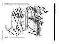
34/35HV CASE WITH DEADBOLT EXPLODED DIAGRAM
1
2
3
4
5
6
17
7
18
8
19
20
21
22
23
24
9
10
11
25
26
12
13
14
27
3
15
16
28
29
30
31
Figure 2.8
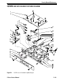
34/35HV case with deadbolt exploded diagram
V Series Service Manual
2–19
Security Device Maintenance
34/35HV case
with deadbolt
parts list
2–20
Refer to Figure 2.8 and the table below to find the part you need.
Item
Part No. Qty.
Description
1
A34087
5
Case cover mounting screws
2
B60481
1
Case cover
3
A34236
2
Wire strain relief
4
A34066
1
Upper auxiliary spring
5
B34020
2
Auxiliary return levers
6
A34065
1
Lower auxiliary spring
8
B60493
1
Motor module
8
A34018
1
Deadlocking spring
9
A61210
1
Auxiliary bolt spring
10
A34315
1
Retaining ring
11
A35002
1
Deadlocking lever
12
A34450
1
Case mounting screw
13
B60467
1
Locking bar
14
B34092
1
Auxiliary bolt
15
D34095
1
Faceplate for deadbolt function
not shown
B34515
1
Faceplate for non-deadbolt function
16
A18722
2
Standard faceplate screws
not shown
A34454
2
Security faceplate screws
17
A34081
1
Hub lever spring
18
B35490
1
Long hub lever
19
B34003
1
Outside hub
20
B34043
1
Inside hub
21
B35019
1
Latchbolt (lever)
not shown
B35018
1
Latchbolt (knob)
22
A34048
1
Stop pin
23
B35035
1
Deadbolt
24
A35004
1
Latch lever
25
A35000
1
Turn knob hub
26
A61250
2
M2 0.4 × 10 m screws
27
A61607
1
Deadbolt sensing switch & wire assembly
28
A35257
1
Clamp plate
29
B61302
1
Case sub-assembly
30
A34045
2
#8–32 × 1/4″ screws
31
C34053
1
Armored front
V Series Service Manual
Security Device Maintenance
34/35HV CASE WITHOUT DEADBOLT EXPLODED DIAGRAM
1
2
3
4
5
6
17
7
18
8
19
20
21
22
9
10
11
23
24
12
25
13
14
15
16
26
27
28
29
Figure 2.9
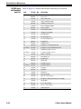
34/35HV case without deadbolt exploded diagram
V Series Service Manual
2–21
Security Device Maintenance
34/35HV case
without
deadbolt
parts list
2–22
Refer to Figure 2.9 and the table below to find the part you need.
Item
Part No. Qty.
Description
1
A34087
5
Case cover mounting screws
2
B60481
1
Case cover
3
A34236
1
Wire strain relief
4
A34066
1
Upper auxiliary spring
5
B34020
2
Auxiliary return levers
6
A34065
1
Lower auxiliary spring
7
B60493
1
Motor module
8
A34018
1
Deadlocking spring
9
A61210
1
Auxiliary bolt spring
10
A34315
1
Retaining ring
11
A35002
1
Deadlocking lever
12
A34450
1
Case mounting screw
13
B60467
1
Locking bar
14
B34092
1
Auxiliary bolt
15
B34515
1
Faceplate for non-deadbolt function
not shown
D34095
1
Faceplate for deadbolt function
16
A18722
2
Standard faceplate screws
not shown
A34454
2
Security faceplate screws
17
A34081
1
Hub lever spring
18
B35490
1
Long hub lever
19
B34003
1
Outside hub
20
B34043
1
Inside hub
21
B35019
1
Latchbolt (lever)
not shown
B35018
1
Latchbolt (knob)
22
A34048
1
Stop pin
23
A35004
1
Latch lever
24
A61250
1
M2 0.4 × 10 m screw
25
A41172
1
Special mortise cam C210
26
A35257
1
Clamp plate
27
B61302
1
Case sub-assembly
28
A34045
2
#8–32 × 1/4″ screws
29
C34053
1
Armored front
V Series Service Manual
Security Device Maintenance
XV CONTROLLER EXPLODED DIAGRAM
12
1
2
11
10
3
O1
N 2
9
4
Figure 2.10
5
6
8
7
XV controller exploded diagram
XV Controller
parts list
V Series Service Manual
Refer to Figure 2.10 and the table below to find the part you need.
Item
Part No. Qty.
1
B80220
2
1765873 2
#6 x 3/8″ sheet metal screws
3
T61928
XV Wiring diagram instruction sticker
4
1762170 1
External power supply battery pack
5
A34510
1
Adhesive strip for battery pack
1
1
1
Description
XV Enclosure cover
6
B80224
7
1765915 4
#6-32 X 5/8″ phil–pan head screws
8
1777517 1
Grounding screw with washer
9
B62098
1
Programmed PROM (VP_ _XV) or
B62075
1
Programmed PROM for XV keypad (VPXVKP)a
10
B61664
1
Micro-controller circuit board
11
1772640 4
#4-40 X 3/8″ phil–pan head screws
12
C80221
XV Enclosure box
1
XV Control electronics
2–23
Security Device Maintenance
not shown
1767179 1
Keypad reader (Lexan illuminated)
not shown
1767210 1
Keypad reader (stainless steel finish)
not shown
1767252 1
Magnetic stripe card reader (off-white finish)
not shown
1767294 1
Magnetic stripe card reader (black finish)
not shown
1789014 1
Motorola proximity reader I (beige finish)
not shown
1788974 1
Motorola proximity reader I (black finish)
not shown
1789056 1
Motorola proximity reader II (beige finish)
not shown
1789098 1
Motorola proximity reader II (black finish)
not shown
1788005 1
HID miniprox proximity reader (grey finish)
not shown
1788047 1
HID miniprox proximity reader (beige finish)
not shown
1788089 1
HID thinline proximity reader (beige finish)
not shown
1788120 1
HID thinline proximity reader (black finish)
a. Use this part for XV units with keypad readers.
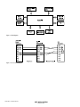
EXTERNAL COMMUNICATIONS EXPLODED DIAGRAM
1
3
2
Figure 2.11 External communications exploded diagram
External
communications
parts list
2–24
Refer to Figure 2.11 and the table below to find the part you need.
Item
Part No. Qty.
Description
1
1767451 1
Wall plate
2
A10055
#6-32 X 3/8″ screws
3
1767493 1
Nine (9) pin male connector
not shown
1768015 1
Nine (9) pin female connector
2
V Series Service Manual
Security Device Maintenance
PROGRAMMING PARTS DIAGRAM
1
7
6
2
5
3
4
Figure 2.12 Programming parts
Programming
parts list
V Series Service Manual
Refer to Figure 2.12 and the table below to find the part you need.
Item
Part No. Description
1
1760849 Intelligent Programmer Software
2
1760922 IPS interface cable
3
1760964 IPS crossover cable
4
1746981 Handheld terminal
5
1754552 Handheld charge cable adapter
6
1754594 Handheld terminal charger
7
1751829 Handheld terminal to lock cable
2–25
Security Device Maintenance
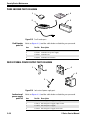
CARD ENCODER PARTS DIAGRAM
4
1
3
2
Figure 2.13 Card Encoder parts
Card Encoder
parts list
Refer to Figure 2.13 and the table below to find the part you need.
Item
Part No. Description
1
1754877 Card Encoder security device
2
1747021 Card Encoder power supply
3
1754751 Card Encoder
4
1754919 Card Encoder Software
LOCK EXTERNAL POWER SUPPLY PARTS DIAGRAM
1
4
3
2
Figure 2.14 Lock external power supply parts
Lock external
power supply
parts list
2–26
Refer to Figure 2.14 and the table below to find the part you need.
Item
Part No. Description
1
1762170 External power supply battery pack
2
1762139 External power supply adapter cable
3
1711519 External power supply
4
1762212 External power supply electronics
V Series Service Manual
Security Device Maintenance
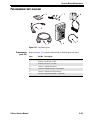
SPECIAL TOOLS DIAGRAM
4
1
2
3
Figure 2.15 Special tools
Special tools
parts list
V Series Service Manual
Refer to Figure 2.15 and the table below to find the part you need.
Item
Part No. Description
1
1723791 ESD kit
2
1702829 McGard driver bit
3
1503525 Standard driver bit
4
1724093 Magnetic stripe reader cleaning card (shipped 50 to a box)
2–27
Security Device Maintenance
FUNCTION DESCRIPTIONS
HV Locks
The following lists describe how the latchbolt, deadbolt, outside
lever/knob, and inside lever/knob operates for each HV function.
FV–Deadbolt with key override
Latchbolt operated by:
■ outside key
■ outside lever/knob—unless locked by
internal motor drive mechanism
■ inside lever/knob
Latchbolt deadlocked by auxiliary latch
Outside lever/knob locked and unlocked by:
internal motor drive mechanism operated
by time–activated electronic signal or by
valid card/PIN (if deadbolt is thrown,
deadbolt override privilege is required)
■
Inside lever/knob is always unlocked
Deadbolt operated by:
outside key
■ inside turn–lever
■ outside lever/knob when lever/knob is
unlocked by internal motor drive
mechanism (retracts only)
■ inside lever/knob (retracts only)
■
LV–Deadbolt without key override
Latchbolt operated by:
■ outside lever/knob—unless locked by
internal motor drive mechanism
■ inside lever/knob (deadlocked by auxiliary
latch)
Latchbolt deadlocked by auxiliary latch
Outside lever/knob locked and unlocked by:
internal motor drive mechanism operated
by time–activated electronic signal or by
valid card/PIN (if deadbolt is thrown,
deadbolt override privilege is required)
■
Inside lever/knob is always unlocked
Deadbolt operated by:
inside turn–lever
■ outside lever/knob when lever/knob is
unlocked by internal motor drive
mechanism (retracts only)
■ inside lever/knob (retracts only)
■
EV–Latch with key override
Latchbolt operated by:
■ outside key
■ outside lever/knob—unless locked by
internal motor drive mechanism
■ inside lever/knob
Outside lever/knob unlocked by:
internal motor drive mechanism operated
by time–activated electronic signal or by
valid card/PIN
■
Inside lever/knob is always unlocked
Outside lever/knob locked by:
internal motor drive mechanism operated
by time–activated electronic signal or by
valid card/PIN
■
2–28
V Series Service Manual
Security Device Maintenance
NV–Latch without key override
Latchbolt operated by:
■ outside lever/knob—unless locked by
internal motor drive mechanism
■ inside lever/knob
Outside lever/knob locked by:
■ internal motor drive mechanism operated
by time–activated electronic signal or by
valid card/PIN
KV Lock
Outside lever/knob unlocked by:
internal motor drive mechanism operated
by time–activated electronic signal or by
valid card/PIN
■
Inside lever/knob is always unlocked
The following list describes how the latchbolt, outside lever/knob, and
inside lever/knob operates for the KV function.
DV–Cylindrical latch with key override
Latchbolt operated by:
■ outside key
■ outside lever/knob—unless locked by
internal motor drive mechanism
■ inside lever/knob
Outside lever/knob unlocked by:
■ internal motor drive mechanism operated
by time–activated electronic signal or by
valid card/PIN
Inside lever/knob is always unlocked
Outside lever/knob locked by:
■ internal motor drive mechanism operated
by time–activated electronic signal or by
valid card/PIN
V Series Service Manual
2–29
Security Device Maintenance
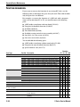
FUNCTION CONVERSION
If you want to convert the function of an existing HV Lock, use the
following table to determine the parts that you need. This table includes
only the parts that are different.
For example, to convert the function of a 34H Lock with a magnetic
stripe card reader from FV to EV, you would remove the following
parts:
■ 34HV inside escutcheon with turn knob (C61421)
■ Faceplate for deadbolt function (D34095)
■ Deadbolt (B35035)
■ Turn knob hub (A35000)
■ Deadbolt sensing switch & wire assembly (A61607)
■ One M2 0.4 x 10 m screw (A61250)
■ One wire strain relief (A34236).
You would add the following parts:
■ 34HV inside escutcheon without turn knob (C61406)
■ Faceplate for non–deadbolt function (B34515)
■ Special mortise cam (A41172).
Part Type
Trim Parts
Outside escutcheon
Inside escutcheon
Case parts
Faceplate
Deadbolt
Turn knob hub
Deadbolt sensing switch
& wire assembly
Special mortise cam
Screw
Wire strain relief
2–30
Function
FV LV EV NV
Part No. Description
C61420
C60447
C61405
C60448
C61400
C60445
C61402
C60446
C61421
C61406
C61401
C61409
34HV outside escutcheon with key (magnetic stripe)
34HV outside escutcheon with key (keypad/proximity)
34HV outside escutcheon without key (magnetic stripe)
34HV outside escutcheon without key (keypad/proximity)
35HV outside escutcheon with key (magnetic stripe)
35HV outside escutcheon with key (keypad/proximity)
35HV outside escutcheon without key (magnetic stripe)
35HV outside escutcheon without key (keypad/proximity)
34HV inside escutcheon with turn knob
34HV inside escutcheon without turn knob
35HV inside escutcheon with turn knob
35HV inside escutcheon without turn knob
!
!
D34095
B34515
B35035
A35000
A61607
Faceplate for deadbolt function
Faceplate for non-deadbolt function
Deadbolt
Turn knob hub (deadbolt)
Deadbolt sensing switch & wire assembly (deadbolt)
!
!
!
!
!
!
!
!
!
!
A41172 Special mortise cam (non deadbolt)
A61250 M2 0.4 x 10 m screw (2 needed for FV and LV, 1 needed
for EV and NV)
A34236 Wire strain relief (2 needed for FV and LV, 1 needed for EV
and NV)
!
!
!
!
!
!
!
!
!
!
!
!
!
!
!
!
!
!
!
!
!
!
!
!
!
!
!
!
!
!
!
!
V Series Service Manual
Security Device Maintenance
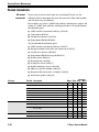
34HV/35HV KNOB/LEVER CONVERSION
If you want to convert an existing 34HV Lock (with knob) to a
35HV Lock (with lever), or vice-versa, use the following table to
determine the parts that you need. This table includes only the parts
that are different.
For example, to convert a 34HV Lock with turn knob, key, and
magnetic strip card reader to a 35HV Lock with lever (with turn knob,
key, and magnetic stripe card reader, you would remove the following
parts:
■
■
■
■
Old knob
34HV outside escutcheon with key (C61420)
34HV inside escutcheon with turn knob (C61421)
Latchbolt for knob (B35018).
You would add the following parts:
■ New lever
■ 35HV outside escutcheon with key (C61400)
■ 35HV inside escutcheon with turn knob (C61401)
■ Latchbolt for lever (B35019)
■ Lower auxiliary spring (A34065)
■ Upper auxiliary spring (A34066)
■ Auxiliary return lever (B34020) (2 needed).
Part Type
Trim Partsa
Outside escutcheon
Inside escutcheon
Case parts
Latchbolt
Lower auxiliary spring
Upper auxiliary spring
Auxiliary return lever
Part No. Description
C61420
C60447
C61405
C60448
C61400
C60445
C61402
C60446
C61421
C61406
C61401
C61409
34HV outside escutcheon with key (magnetic stripe)
34HV outside escutcheon with key (keypad/proximity)
34HV outside escutcheon without key (magnetic stripe)
34HV outside escutcheon without key (keypad/proximity)
35HV outside escutcheon with key (magnetic stripe)
35HV outside escutcheon with key (keypad/proximity)
35HV outside escutcheon without key (magnetic stripe)
35HV outside escutcheon without key (keypad/proximity)
34HV inside escutcheon with turn knob
34HV inside escutcheon without turn knob
35HV inside escutcheon with turn knob
35HV inside escutcheon without turn knob
B35018 Latchbolt (knob)
B35019 Latchbolt (lever)
A34065 Lower auxiliary spring
A34066 Upper auxiliary spring
B34020 Auxiliary return lever (2 needed)
Knob Lever
!
!
!
!
!
!
!
!
!
!
!
!
!
!
!
!
!
a. Refer to the H Series Service Manual for additional trim parts.
V Series Service Manual
2–31
Security Device Maintenance
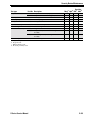
READER CONVERSION
HV reader
conversion
If you want to convert the reader of an existing HV Lock, use the
following table to determine the parts that you need. This table includes
only the parts that are different.
For example, to convert a 34HV Lock with key and magnetic stripe card
reader to a 34HV Lock with key and keypad reader, you would remove
the following parts:
■
■
■
■
34HV outside escutcheon with key (C61420)
Card reader (B61646)
Outside wire harness (A61643)
Programmed PROM (B62099).
You would add the following parts:
■
■
■
■
■
■
■
■
■
■
■
34HV outside escutcheon with key (C60447)
Keypad assembly with cable and connector (C60325)
Outside wire harness (B60305)
Programmed PROM for keypad (B62076)
Reader gasket (B60321)
Retaining ring (A60318)
Sealing lens cover (A60317)
Reader mounting screws (A60348)
Adhesive tape for sounder (A60324)
Keypad reader electronics assembly (C60303)
Escutcheon gasket (A60316).
Part type
Part No. Description
Outside escutcheon
C61420
C60447
C61405
C60448
C61400
C60445
C61402
C60446
B61646
C60325
C60342
Reader
Outside wire harness
2–32
34HV outside escutcheon with key
34HV outside escutcheon with key
34HV outside escutcheon without key
34HV outside escutcheon without key
35HV outside escutcheon with key
35HV outside escutcheon with key
35HV outside escutcheon without key
35HV outside escutcheon without key
Card reader
Keypad assembly with cable and connector
HID proximity bezel with antennae &
IR assembly
C60337 Motorola proximity bezel with reader assembly
A61643 Outside wire harness
B60305 Outside wire harness
Proximity
Mag.a Kpd.b HIDc Mot.d
!
!
!
!
!
!
!
!
!
!
!
!
!
!
!
!
!
!
!
!
!
!
!
!
V Series Service Manual
Security Device Maintenance
Part type
Part No. Description
Programmed PROM
Programmed PROM (VP_S15)
Programmed PROM for keypad (VP15KP)
Reader gasket
Retaining ring
Sealing lens cover
Reader mounting screws
Adhesive tape for sounder
Keypad reader electronics assembly
HID proximity reader with wake up electronics
assembly
B60338 Motorola proximity wake up electronics
assembly
A60316 Escutcheon gasket
B62099
B62076
Reader gasket
B60321
Retaining ring
A60318
Sealing lens cover
A60317
Reader mounting screws A60348
Adhesive tape
A60324
Electronics assembly
C60303
B60339
Escutcheon gasket
a.
b.
c.
d.
Proximity
Mag.a Kpd.b HIDc Mot.d
!
!
!
!
!
!
!
!
!
!
!
!
!
!
!
!
!
!
!
!
!
!
!
!
!
Magnetic stripe reader
Keypad reader
HID proximity reader
Motorola proximity reader
V Series Service Manual
2–33
Security Device Maintenance
KV reader
conversion
If you want to convert the reader of an existing KV Lock, use the
following table to determine the parts that you need. This table includes
only the parts that are different.
For example, to convert an 8KV Lock with a magnetic stripe card
reader to a 8KV Lock with a Motorola proximity reader, you would
remove the following parts:
■
■
■
8KV outside escutcheon (C61405)
Card reader (B61646)
Outside wire harness (A61643).
You would add the following parts:
■
■
■
■
■
■
■
■
■
■
8KV outside escutcheon (C60448)
Motorola proximity bezel with reader assembly (C60337)
Outside wire harness (B60305)
Reader gasket (B60321)
Retaining ring (A60318)
Sealing lens cover (A60317)
Reader mounting screws (A60348)
Adhesive tape for sounder (A60324)
Motorola proximity wake up electronics assembly (B60338)
Escutcheon gasket (A60316).
Part Type
Part No. Description
Outside escutcheon
C61405 8KV outside escutcheon
Proximity
Mag.a Kpd.b HIDc Mot.d
!
C60448 8KV outside escutcheon
C61403 9KV outside escutcheon
C60449 9KV outside escutcheon
Reader
B61646
Card reader
!
!
!
!
!
!
!
!
!
C60325 Keypad assembly with cable and connector
!
C60342 HID proximity bezel with antennae &
IR assembly
!
C60337 Motorola proximity bezel with reader assembly
Outside wire harness
A61643
Outside wire harness
!
!
!
!
!
!
!
!
!
A60318 Retaining ring
!
!
!
A60317
!
!
!
Reader mounting screws A60348 Reader mounting screws
!
!
!
Adhesive tape for
sounder
!
!
!
B60305
Outside wire harness
B62099
Programmed PROM (VP_S15)
B62076
Programmed PROM for keypad (VP15KP)
!
Reader gasket
B60321
Reader gasket
Retaining ring
Sealing lens cover
Programmed PROM
2–34
A60324
Sealing lens cover
Adhesive tape for sounder
!
V Series Service Manual
Security Device Maintenance
Part Type
Part No. Description
Electronics assembly
C60303 Keypad reader electronics assembly
Escutcheon gasket
a.
b.
c.
d.
B60339
HID proximity reader with wake up electronics
assembly
B60338
Motorola proximity wake up electronics
assembly
A60316
Escutcheon gasket
Proximity
Mag. Kpd. HIDc Mot.d
a
b
!
!
!
!
!
!
Magnetic stripe reader
Keypad reader
HID proximity reader
Motorola proximity reader
V Series Service Manual
2–35
Security Device Maintenance
REPLACING PARTS
Caution
Replacing
batteries
Before you handle the circuit board or any component on the circuit
board, make sure that you are properly grounded using an
electrostatic discharge (ESD) protection kit. When ordering an ESD
protection kit, refer to the part number on page 2–27. Touching the
circuit board without proper grounding can damage sensitive
electronic components—even if you don’t notice any static discharge.
The battery pack consists of four AA alkaline batteries. The expected
battery life is two years for 8KV and 9KV, and three years for 30HV
locks (used at a rate of twenty times per day and 365 days per year). The
battery life for keypad locks and proximity locks is slightly shorter.
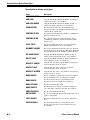
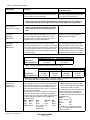
When to replace batteries
You know that it’s time to replace the battery pack when you start to
encounter a different response than normal when using a token to
access the lock. Refer to the table below to determine whether the
battery pack should be replaced.
When access is… and you see… and you hear… The battery voltage level is…
Granted
green flashes
Granted with a
2-second delay
green flashes
Denieda
red & green
flashes
Denied
normal
beeps
low with limited accesses
remaining
very low
dead
a. Access to operating tokens is denied, but access to programming functions is still allowed
using a communication token. To unlock the door when the battery is at this level, access
programming with the communication token and set the door mode to “door unlock”.
Special tools
The battery compartment cover is secured by either a torx head or a
McGard head screw. Use the appropriate bit to remove and replace the
battery compartment cover. When ordering a torx bit driver or a
McGard bit driver, refer to the part numbers on page 2–27.
Replacing the battery pack
Replacing the battery pack is a completely safe operation. When you
remove the battery pack, the backup battery temporarily takes over the
maintenance of the lock’s clock and memory. Then, after the new
battery pack is connected, the battery pack resumes maintenance of the
clock and memory.
2–36
V Series Service Manual
Security Device Maintenance
The only purpose of the backup battery is to support the clock and
memory if power is not available from the battery pack. After the
batteries in the battery pack fail, the backup battery can maintain the
clock and memory for several years.
To replace the battery pack:
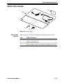
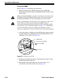
Refer to Figure 2.16 and follow the steps below.
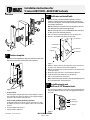
1. Open the battery compartment by removing the security screw and
the battery compartment cover.
Battery compartment cover
Security screw
Tabs
Figure 2.16 Removing and replacing the battery compartment cover
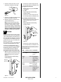
2. Remove the battery pack from the compartment.
3. Disconnect the old battery pack, as shown in Figure 2.17, and
connect the new battery pack.
Disconnect here
Battery pack
Figure 2.17 Disconnecting the old battery pack
V Series Service Manual
2–37
Security Device Maintenance
4. Position the new battery pack in the battery compartment.
5. Insert the tabs on the lower edge of the battery compartment door
into the battery compartment. Swing the door closed. Install the
security screw.
Removing and
reinstalling the
inside and
outside trim
To remove the inside and outside trim:
Refer to Figure 2.18 and follow the steps below.
1. Open the battery compartment by removing the security screw and
the battery compartment cover.
2. Remove the battery pack from the battery compartment.
3. Disconnect the battery pack.
4. Remove the inside knob or lever.
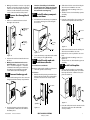
5. From the inside of the door, remove the upper and lower
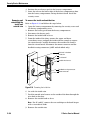
escutcheon screws and pull the inside trim out enough to expose
the circuit board. Carefully disconnect the outside wire harness
from the circuit board. Disconnect the motor connector and the
deadbolt sensing connector (30HV with deadbolt only).
Wire hole in the door
Inside trim
Circuit board
Outside wire harness
Deadbolt sensing connector
Motor connector
Figure 2.18 Removing the inside trim
6. Set aside the inside trim.
7. Feed the outside wire harness to the outside of the door through the
wire hole in the door.
8. Remove the outside knob or lever.
Note: For 8V and 9V, remove the core and depress the knob keeper
with a screwdriver blade.
9. Remove the outside trim.
2–38
V Series Service Manual
Security Device Maintenance
To reinstall the inside and outside trim:
1. Holding the outside trim near its position on the door, feed the
outside wire harness back through the wire hole to the inside of the
door.
2. Reconnect the outside wire harness to the circuit board in the inside
trim. Reconnect the motor wire connector and deadbolt sensing
connector (for 30HV with deadbolt only).
Note: It is possible to plug the battery pack into the motor connector
and the motor wire into the battery connector. To avoid this,
connect only the connectors with matching wire colors.
3. Position the inside trim against the door and pull the outside wire
harness back through to the outside of the door until the wire
harness is taught.
4. Making sure that the trim does not pinch the wires, secure the
inside and outside trim to the door from the inside. Use the
combination mounting screw in the top mounting hole and the
standard screw in the bottom mounting hole. Do not tighten the
screws completely.
5. Reinstall the inside and outside knobs or levers.
6. Reconnect the battery pack.
7. Position the battery pack in the battery compartment.
8. Insert the tabs on the lower edge of the battery compartment door
into the battery compartment. Swing the door closed. Install the
security screw.
9. Tighten the trim mounting screws firmly.
Replacing the
wire harnesses
V Series Service Manual
To replace the inside wire harness:
1. Open the battery compartment by removing the security screw and
the battery compartment cover.
2. Remove the battery pack from the battery compartment.
3. Disconnect the battery pack.
4. Remove the inside knob or lever.
5. From the inside of the door, remove the upper and lower
escutcheon screws and pull the inside trim out enough to expose
the circuit board. Carefully disconnect the outside wire harness
from the circuit board. Disconnect the motor connector and the
deadbolt sensing connectors (30HV with deadbolt only).
6. Unfasten the coin–cell battery from the inside trim.
7. Release the wires from the wire clamp on the inside trim.
2–39
Security Device Maintenance
Caution
Disconnecting the inside wire harness will cause all security device
information to be lost and revert the security device to its factory
default settings. You must reprogram the security device after
disconnecting the inside cable harness.
8. Disconnect the inside wire harness from the circuit board in the
inside trim.
9. Wait at least 30 seconds, then connect the new inside wire harness
to the circuit board in the inside trim.
Note: The pair of connectors is keyed to connect only one way.
10. Slide the motor and deadbolt sensing wires into the wire clamp on
the inside trim.
11. Fasten the coin–cell battery to the inside trim.
12. Connect the motor connector and deadbolt sensing connector
(30HV only).
Note: It is possible to plug the battery pack into the motor connector
and the motor wire into the battery connector. To avoid this,
connect only the connectors with matching wire colors.
13. Position the inside trim against the door and pull the outside wire
harness back through to the outside of the door until the wire
harness is taught.
14. Making sure that the trim does not pinch the wires, secure the
inside and outside trim to the door from the inside. Use the
combination mounting screw in the top mounting hole and the
standard screw in the bottom mounting hole. Tighten the screws
firmly.
15. Position the battery pack in the battery compartment.
16. Reconnect the battery pack.
17. Insert the tabs on the lower edge of the battery compartment door
into the battery compartment. Swing the door closed. Install the
security screw.
18. Use the temporary communication token to enter the programming
mode.
19. Reprogram the security device. See the V Series Handheld
Terminal User Manual or the V Series Intelligent Programmer
Software User Manual for more information.
2–40
V Series Service Manual
Security Device Maintenance
To replace the outside wire harness:
Note: Disconnecting the outside wire harness will not cause any
security device information to be lost.
1. Remove the inside and outside trim. For instructions, see To remove
the inside and outside trim: on page 2-38.
2. If you are replacing a keypad reader or proximity card reader,
remove the gasket that covers the circuit board for the card reader.
3. Loosen the screw holding the harness clip and remove the clip. Save
the clip.
4. Disconnect the wire harness from the circuit board on the card
reader or keypad reader.
5. Remove the communication port retainer clip. Save the clip.
6. Release the wires from the wire clamp on the outside trim to free
the wire harness.
7. Connect the new wire harness to circuit board on the card reader or
keypad reader.
8. Slide the harness clip under the loosened screw. Tighten the screw.
9. Slide the communication port wires under the wire clamp.
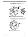
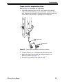
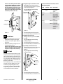
10. Position the communication port, as shown in Figure 2.19. Secure
the port with the retainer clip.
Note the position of the
pins and keyed hole
Figure 2.19 Orienting the communication port
11. If you are replacing a keypad reader or proximity card reader,
reinstall the gasket over the circuit board on the card reader with
the adhesive side towards the circuit board.
12. Reinstall the inside and outside trim. For instructions, see To
reinstall the inside and outside trim: on page 2-39.
V Series Service Manual
2–41
Security Device Maintenance
Replacing the
inside circuit
board
Caution
To replace the inside circuit board:
1. Remove the inside and outside trim. For instructions, see To remove
the inside and outside trim: on page 2-38.
Before you handle the circuit board or any component on the circuit
board, make sure that you are properly grounded using an
electrostatic discharge (ESD) protection kit. When ordering an ESD
protection kit, refer to the part number on page 2–27. Touching the
circuit board without proper grounding can damage sensitive
electronic components—even if you don’t notice any static discharge.
2. Disconnect the inside wire harness from the circuit board.
3. Unscrew the four circuit board mounting screws. Save the screws.
4. Remove the circuit board and place it in an anti-static bag.
Note: You may need to remove the PROM from the existing circuit
board and install it into the new circuit board. For more
information, see Replacing the PROM on page 2-44.
5. Position the new circuit board in the inside trim and secure it using
the four circuit board mounting screws.
6. Reconnect the inside wire harness to the circuit board.
7. Reinstall the inside and outside trim. For instructions, see To
reinstall the inside and outside trim: on page 2-39.
Replacing the
card reader or
keypad reader
To replace a magnetic stripe card reader, replace the:
■
reader only.
To replace a keypad reader, replace the:
■
■
keypad assembly
reader electronics.
To replace a proximity card reader, replace the:
■
■
proximity bezel
wake-up electronics assembly.
To replace the magnetic card reader
1. Remove the inside and outside trim. For instructions, see To remove
the inside and outside trim: on page 2-38.
2. Unscrew the two circuit board mounting screws. Save the harness
clip and screws.
3. Disconnect the outside wire harness from the circuit board on the
card reader.
4. Remove the card reader.
5. Position the new card reader in the outside trim and secure it with
the two mounting screws. Do not tighten the left screw.
2–42
V Series Service Manual
Security Device Maintenance
6. Connect the outside wire harness to the circuit board on the card
reader.
7. Position the clip under the left mounting screw. Tighten the screw.
8. Reinstall the inside and outside trim. For instructions, see To
reinstall the inside and outside trim: on page 2-39.
To replace the keypad reader or proximity bezel:
1. Remove the inside and outside trim. For instructions, see To remove
the inside and outside trim: on page 2-38.
2. Remove the gasket that covers the keypad reader electronics
assembly or the proximity wake–up electronics assembly.
3. Unscrew the two electronics assembly mounting screws. Save the
harness clip and screws.
4. Disconnect the outside wire harness from the electronics assembly.
Caution
Before you handle the circuit board or any component on the circuit
board, make sure that you are properly grounded using an
electrostatic discharge (ESD) protection kit. When ordering an ESD
protection kit, refer to the part number on page 2–27. Touching the
circuit board without proper grounding can damage sensitive
electronic components—even if you don’t notice any static discharge.
5. Carefully lift the electronics assembly out of the outside trim.
6. Disconnect the ribbon cable(s) from the back of the electronics
assembly.
7. Remove the four keypad or bezel mounting screws. Remove the
keypad reader or proximity bezel.
8. Orient the new keypad reader or proximity bezel. Feed the ribbon
cable connector(s) through the slot in the outside trim.
9. Holding the keypad reader or proximity bezel in position against the
trim, install the four mounting screws.
10. Connect the ribbon cable(s) to the electronics assembly. Make sure
that all of the pins are inserted in the connector(s).
11. Position the electronics assembly in the outside trim. Secure it with
the four mounting screws. Do not tighten the left screw.
12. Connect the outside wire harness to the electronics assembly.
13. Position the clip under the left mounting screw. Tighten the screw.
14. Reinstall the gasket over the electronics assembly with the adhesive
side towards the electronics assembly.
15. Reinstall the inside and outside trim. For instructions, see To
reinstall the inside and outside trim: on page 2-39.
V Series Service Manual
2–43
Security Device Maintenance
Replacing the
PROM
The Programmable Read-Only Memory (PROM) stores the program that
controls the operation of the V Series Security Device. From time to
time, BEST might upgrade the PROM either to add new features and
functions or to fix problems. Follow the instructions below to upgrade
the security device by replacing the PROM.
Circuit boards may be shipped without the PROM. If you are replacing
the circuit board, you will need to remove the PROM from the existing
circuit board and install it in the new circuit board, or you will need to
install a new PROM. Follow the instructions below.
Note: To remove the PROM without damaging the PROM socket, use a
tool specifically made for this purpose. You can purchase a PROM
removal tool at most electronics supply stores, or contact your local
BEST representative.
To remove the PROM:
Refer to Figure 2.20 and Figure 2.21 and follow the steps below.
1. For the V Series Electronic Lock, remove the inside and outside
trim. For instructions, see To remove the inside and outside trim:
on page 2-38. For the V Series Controller, remove the enclosure
cover.
Caution
Before you handle the circuit board or any component on the circuit
board, make sure that you are properly grounded using an
electrostatic discharge (ESD) protection kit. When ordering an ESD
protection kit, refer to the part number on page 2–27. Touching the
circuit board without proper grounding can damage sensitive
electronic components—even if you don’t notice any static discharge.
2. For the V Series Electronic Lock, disconnect the inside wire harness
and the outside wire harness from the circuit board in the inside
trim.
When performing step 3, do not force the PROM out of its socket.
Prying too far or too forcefully may damage the PROM socket.
Caution
2–44
V Series Service Manual
Security Device Maintenance
3. Insert the hook of the PROM removal tool in one of the notched
corners of the PROM socket, as shown in Figure 2.20. Use the
PROM removal tool to pry the corner of the PROM part way out of
the socket.
PROM socket
PROM
PROM removal tool
CK
T LO
T LO
CK
CO
RP.
CO
RP.
Figure 2.20 Prying one corner of the PROM part way out of the socket
[V Series electronic lock shown]
4. Insert the PROM tool in the opposite notched corner. Pry the PROM
the rest of the way out of the socket, as shown in Figure 2.21.
Opposite corner of
the PROM socket
T LO
CK
CO
RP.
Figure 2.21 Prying the opposite corner of the PROM
V Series Service Manual
2–45
Security Device Maintenance
To install the PROM:
Refer to Figure 2.22 and follow the steps below.
1. Before inserting the new PROM, make sure that the PROM is
oriented so that the flat corner of the PROM matches the flat corner
of the socket.
Caution
Caution
Make sure that the PROM is oriented correctly before inserting it into
the PROM socket. The PROM will fit into the socket the wrong way!
Installing the PROM incorrectly will damage the circuit board.
Before you handle the circuit board or any component on the circuit
board, make sure that you are properly grounded using an
electrostatic discharge (ESD) protection kit. When ordering an ESD
protection kit, refer to the part number on page 2–27. Touching the
circuit board without proper grounding can damage sensitive
electronic components—even if you don’t notice any static discharge.
2. Using your fingers, carefully place the PROM in the correct position
over the socket. Press firmly on the face of the PROM until it seats
completely in the socket. See Figure 2.22.
.
PROM socket
Flat corner on the PROM
Face of the PROM
TL
OC
KC
OR
P.
Press firmly.
Figure 2.22 Inserting the new PROM
3. Reconnect the inside wire harness and outside wire harness to the
circuit board in the inside trim.
4. Reinstall the inside and outside trim. For instructions, see To
reinstall the inside and outside trim: on page 2-39.
2–46
V Series Service Manual
3
TROUBLESHOOTING
EMERGENCY OPERATIONS
Caution
How do you
enable
communications
if you have lost
the token or
forgotten the
password?
Before you handle the circuit board or any component on the circuit
board, make sure that you are properly grounded using an
electrostatic discharge (ESD) protection kit. When ordering an ESD
protection kit, refer to the part number on page 2–27. Touching the
circuit board without proper grounding can damage sensitive
electronic components—even if you don’t notice any static discharge.
If the communication token is lost or unavailable, you can enable
communications by using the two switches on the circuit board inside
the security device. This procedure is equivalent to using a valid
communication token, except a password is not required. This
procedure will not affect the user database, history, or the security
device configuration. You can reset the security device via
programming.
To enable communications without the communication token:
Refer to Figure 3.1 and follow the steps below.
1. Connect the handheld terminal to the security device. For
instructions, see the V Series Handheld Terminal User’s Manual.
2. Turn on the handheld terminal.
3. Remove the inside and outside trim from the door. For more
instructions, see To remove the inside and outside trim: on
page 2-38.
4. Reconnect the outside wire harness to the circuit board in the inside
trim.
V Series Service Manual
3–1
Troubleshooting
5. Locate the DIP switches on the circuit board in the inside trim and
move switch 2 to the ON position.
O
N
DIP switches
O1 2
N
Figure 3.1
Enabling communications using the DIP switches
6. Move switch 1 to the ON position. Both switches should now be in
the ON position.
7. Move both switches back to the OFF position. It does not matter
which switch you move first.
Caution
This function only enables communication and should be used only
when you either forget your password or lose your communication
token. The security device will not work until you return both
switches to the OFF position.
8. When you’ve finished communications and exited communication
mode, disconnect the outside wire harness from the circuit board
and reassemble the inside and outside trim on the door. For more
instructions, see To reinstall the inside and outside trim: on
page 2-39.
How do you
open a lock
after a
complete
battery failure?
3–2
If you were not able to replace the batteries before they expired and
cannot unlock the door, don’t worry! If the lock does not have a key
override feature, you still can unlock the door and access the lock’s
battery compartment.
Note: The low battery alarm may have to be cancelled. To do this, use
the terminal mode in the IPS software, or connect the handheld
terminal, and follow the prompts.
V Series Service Manual
Troubleshooting
To open a lock after complete battery failure:
Refer to Figure 3.2 and follow the steps below.
1. To provide temporary power to the lock, connect the palmtop
cable, with an external battery pack connected, to the base of the
lock. Although the palmtop PC itself does not need to be connected
to the cable, it will not cause a problem if it is connected.
Palmtop cable
Battery pack
Figure 3.2
Connecting the palmtop cable to the base of the lock
2. To open the door, use a valid operating token for the lock.
3. Replace the lock’s battery pack. For more instructions, see
Replacing batteries on page 2-36.
4. Disconnect the palmtop cable from the lock.
V Series Service Manual
3–3
Troubleshooting
TROUBLESHOOTING THE V SERIES ELECTRONIC LOCK
This table summarizes the possible causes for certain lock problems
based on visible and audible signals (LEDs, sounder, and whether access
is granted or denied). The causes of failure are listed in the order of
likelihood. (The most likely cause is first, and so forth.)
Another helpful tool to use when troubleshooting the V Series
Electronic Lock and the V Series Controller is the lock’s history of
events. Appendix B lists the types of events recorded in the history and
their meaning. For information about retrieving, viewing, and printing
history records, see the IPS User Manual or the Handheld Terminal
User Manual.
LEDs
Sounder Access Possible causes include…
Green
Red
1 long
tone
Denied
Token reader cannot read the
token correctly.
Use the token at a moderate speed.
1 short
tone
Denied
a. Card was used, but not
removed soon enough.
a. Try using the card again.
b. Variable card format error
occurred.
b. Check the variable card format.
a. Token number is invalid.
a. Check the access privileges.
b. Time zone is invalid.
b. Check the access privileges.
c. Card is damaged.
c. Re-encode the operating card. It may be
possible to re-encode a damaged card. If not,
issue a new operating card.
d. Lock has not been
programmed.
d. Program the lock.
e. Facility code is invalid.
e. Program the correct facility code in the lock.
f. Token has expired.
f. Re-program the lock with a valid expiration
date.
g. Lock may be in a lock down
mode.
g. Check to see if a door lock mode is active by
using the handheld terminal to review the
door mode. If desired, set the door mode to
TZ Control.
2 short
tones
Red & 2 short
green tones
3–4
You should…
Granted Condition is normal for a valid
token.
Denied
Denied
Token does not have the deadbolt Either program the token to have the deadbolt
override privilege.
override privilege, or instruct the user that his
or her token cannot access the lock when the
deadbolt is thrown.
V Series Service Manual
Troubleshooting
LEDs
Sounder Access Possible causes include…
Denied
You should…
a. Card reader needs cleaning.
a. Clean the card reader head using a cleaning
card for magnetic stripe card readers.
b. Outside wire harness is
damaged or disconnected.
b. Check the outside wire harness. If it’s
damaged, replace the wire harness.
c. Card reader or keypad reader
has failed.
c. Replace the card reader or keypad reader.
d. Foreign object is inserted in
the card reader.
d. Remove the object or replace the card
reader.
e. Battery pack is faulty.
e. Check the battery pack. Replace it, if
necessary.
f. Circuit board is
malfunctioning.
f. Replace the circuit board.
g. Circuit board failed for an
g. Replace the circuit board.
unknown reason.
Note: If the above condition
exists, the key override may be
used to access the door. If the
lock has no key override, call
your local BEST representative.
Green
h. Check the inside wire harness.
i. Self-aligning trim is
overtightened.
i. Loosen the self-aligning trim.
Granted Battery is low.
after
delay
Change the battery pack. For more information,
see Replacing batteries on page 2-36.
Red &
green
Denied
Battery is very low.
Change the battery pack.
Green
stays
on
Denied
a. Communication token was
used.
a. Wait 1 minute for the lock communications
to automatically expire, or use any token
again to turn off communications.
b. Circuit board switches are in
the ON position.
b. Remove the trim and set the switches to the
OFF position. For more information, see To
remove the inside and outside trim: on
page 2-38.
a. Sounder is damaged.
a. Replace the card reader or keypad reader.
b. Circuit board is
malfunctioning.
b. Replace the circuit board.
Red
4 short
tones
h. Inside wire harness is
disconnected from the motor
or is damaged.
Denied
Granted a. LEDs are damaged.
b. Circuit board is
malfunctioning.
V Series Service Manual
a. Replace the card reader or keypad reader.
b. Replace circuit board.
3–5
Troubleshooting
LEDs
Green
Sounder Access Possible causes include…
Denied
a. Chassis type of cylindrical lock a. Change the programming setting for chassis
is set to “mortise”.
type to cylindrical.
b. If the lock is a 9K, the spindle
may be faulty.
Lock is always unlocked.
You should…
b. If you can hear the chassis cycling, replace
the chassis. Contact your local BEST
representative for assistance.
a. Lock may be in a door unlock a. Use the handheld terminal to check the door
mode. If desired, change the door mode.
mode or passage mode. Setting
the door mode to “Door
unlock” means that anyone
can access the door in this
condition.
b. Lock may be in a door unlock
time zone.
b. Use the handheld terminal to check the door
mode and the time zone settings. If desired,
change the door mode.
Cannot plug the handheld a. Foreign object is jammed into
terminal connector into
the communications port.
the lock’s communications b. Communications port is
port.
damaged.
a. Remove the object from the communications
port.
Cannot insert a card.
Push the object down through the card reader if
possible. Unless the object is preventing the
card from being inserted fully, there is no
reason to remove the trim.
If the object will not push through the card
reader, remove the trim and remove the foreign
object.
Note: Use a valid card to verify that the card
reader head is not damaged.
Foreign object is jammed in the
card reader.
b. Replace the outside wire harness.
When communicating
a. Communications cable(s) is
a. Check cable connections.
between a PC or palmtop
(are) not connected properly.
and a V Series Security
b. If the device is an electronic
b. Check the outside wire harness. If it’s
Device, or between a PC
lock, the lock’s outside wiring
damaged, replace the wire harness.
and a palmtop, you see a
harness is damaged or
message that
disconnected.
communications has failed.
c. Communications cable is
c. Try communicating with another device or
faulty or damaged.
PC. If communications works, the cable(s) is
(are) not the problem. If communications
does not work, replace the cable(s).
3–6
V Series Service Manual
Troubleshooting
TROUBLESHOOTING THE V SERIES CONTROLLER
For readers with
red and green LEDs
and no sounder
This table summarizes the possible causes for certain controller
problems based on visible signals (LEDs and whether access is granted
or denied). Causes of failure are listed in order of likelihood. (The most
likely cause is first, and so forth.)
Before troubleshooting problems with the V Series Controller, it’s a
good practice to confirm that the DIP switches on the controller board
are set properly. For instructions, see Figure 1–Controller board
wiring diagram in the V Series Controller Installation Instructions,
which are included in Appendix C.
LEDs
Access Possible causes include…
You should…
Green Granted Condition is normal for a valid
token.
Denied
a. Token reader cannot read the
token correctly.
a. Use the token at a moderate speed.
b. Card reader needs cleaning.
b. Clean the card reader head using a cleaning
card for magnetic stripe card readers.
c. Connection to the card reader c. Check all connections.
or keypad reader is bad.
Red
Denied
d. Foreign object is inserted into
the card reader.
d. Remove the object or replace the card
reader.
e. LEDs are damaged.
e. Replace the card reader or keypad reader.
a. Token number is invalid.
a. Check the access privileges.
b. Time zone is invalid.
b. Check the access privileges.
c. Card is damaged.
c. Re-encode the operating card. It may be
possible to re-encode a damaged card. If not,
issue a new operating card.
d. Controller has not been
programed.
d. Program the controller.
e. Facility code is invalid.
e. Program the correct facility code in the
controller.
f. Token has expired.
f. Re-program the token with a valid expiration
date.
g. Controller may be in a lock
down mode.
g. Check to see if a door lock mode is active by
using the handheld device to review the
door mode. If desired, set the door mode to
TZ Control.
V Series Service Manual
3–7
Troubleshooting
LEDs
Access Possible causes include…
You should…
Green
stays
on
Denied
a. Communication token was
used.
a. Wait 1 minute for the lock communications
to automatically expire, or use any token
again to turn off communications.
b. Micro-controller circuit board
switches are in the ON
position.
b. Set the switches to the OFF position.
c. Micro-controller circuit board
is malfunctioning.
c. Replace the micro-controller circuit board.
d. XV Controller electronics
circuit board is
malfunctioning.
d. Replace the micro-controller circuit board.
Door is always
unlocked.
a. Use the handheld terminal to check the door
a. Controller may be in a door
mode. If desired, change the door mode.
unlock mode or passage mode.
Setting the door mode to
“Door unlock” means that
anyone can access the door in
this condition.
b. Controller may be in a door
unlock time zone.
b. Use the handheld terminal to check the door
mode and time zone settings.
c. Locking device may not be
connected properly.
c. Check the connections.
Cannot plug the a. Foreign object is jammed in
handheld
the communications port.
connector into b. Communications port is
the controller’s
damaged.
communications
port.
3–8
a. Clear the object from the communications
port.
b. Replace the communications port.
V Series Service Manual
Troubleshooting
For readers with a
dual red/green LED
and sounder
LEDs
Sounder Access Possible causes include…
Green
Green/ 2 short
red
tones
flashing
Green/ 2 short
red
tones
flashing
Green/
red
flashing
You should…
Granted Condition is normal for a valid
token.
1 long
tone
Green
remains
on
This table summarizes the possible causes for certain controller
problems based on visible and audible signals (LEDs, sounder, and
whether access is granted or denied). The causes of failure are listed in
the order of likelihood. (The most likely cause is first, and so forth.)
Denied
Token reader cannot read the
token correctly.
Use the token at a moderate speed.
Denied
a. Token number is invalid.
a. Check the access privileges.
b. Time zone is invalid.
b. Check the access privileges.
c. Card is damaged.
c. Re-encode the operating card. It may be
possible to re-encode a damaged card. If not,
issue a new operating card.
d. Controller has not been
programmed.
d. Program the controller.
e. Facility code is invalid.
e. Program the correct facility code in the
controller.
f. Token has expired.
f. Re-encode the token with a valid expiration
date.
Denied
Controller may be in a lock down Use the handheld terminal to check the door
mode.
mode. If desired, set the door mode to TZ
Control.
Denied
a. Card reader needs cleaning.
a. Clean the card reader head using a cleaning
card for magnetic stripe card readers.
b. Card or keypad reader has
failed.
b. Replace the card or keypad reader.
c. Card is damaged.
c. Try other cards in the reader. If another card
accesses the controller, the problem involves
the card. Replace the card reader if other
cards do not access the controller.
a. Communication token was
used.
a. Wait 1 minute for the lock communications
to automatically expire, or use any token
again to turn off communications.
b. Micro-controller circuit board
switches are in the ON
position.
b. Set the switches to the OFF position.
Denied
Sounder is damaged.
Replace the card reader or keypad reader.
Denied
LEDs are damaged.
Replace the card reader or keypad reader.
Denied
V Series Service Manual
3–9
Troubleshooting
LEDs
Sounder Access Possible causes include…
Door is always unlocked.
a. Use the handheld terminal to check the door
a. Controller may be in a door
mode. If desired, change the door mode.
unlock mode or passage mode.
Setting the door mode to
“Door unlock” means that
anyone can access the door in
this condition.
b. Controller may be in a door
unlock time zone.
b. Use the handheld terminal to check the door
mode and time zone settings.
c. Locking device may not be
connected properly.
c. Check the connections.
Cannot plug the handheld
a. Foreign object is jammed in
terminal connector into the
the communications port.
controller’s communications
port.
b. Communications port is
damaged.
3–10
You should…
a. Clear the object from the communications
port.
b. Replace the communications port.
V Series Service Manual
Troubleshooting
Alarm
troubleshooting
This table summarizes the possible causes of valid and false alarms
based on the type of alarm (siren, strobe, or security system) indicated
(or not indicated). The causes are listed in the order of likelihood. (The
most likely cause is first, and so forth.)
You notice…
Possible causes include…
A local alarm (the card or keypad
reader’s own alarm sounds and/or
displays).
a. Door is propped open, triggering a. Secure the door. You may want
the Door Open Too Long (DOTL)
to change the DOTL alarm
alarm.
settings with the IPS program or
handheld terminal to allow more
time to close the door.
Alarm output device is triggered.
This device could be a siren, a
strobe, a security system, or any
combination of security alarm
functions.
No alarm (when expected).
V Series Service Manual
You should…
b. Door contact wiring is
disconnected, loose, or cut.
b. Secure all of the door wiring.
c. Door is not latched completely.
c. Secure the door. You may want
to install a door closer if the door
does not have one, or adjust the
door closer.
d. Door latch is taped retracted so
that it does not latch in the door
strike.
d. Remove the tape and secure the
door.
e. Door contact is bad.
e. Replace the door contact.
a. Entry has been forced.
a. Secure the door.
b. Door is propped open, triggering b. Secure the door. You may want
the Door Open Too Long (DOTL)
to change the DOTL alarm
alarm.
settings with the IPS program or
handheld terminal to allow more
time to close the door.
c. Controller has been tampered
with.
c. Secure the door.
d. Door contact type has been
specified incorrectly.
d. Change the door contact
information with the IPS program
or handheld terminal.
e. Door has been accessed using a
key.
e. Cancel the alarm. Remind the key
holders to disarm the alarm
system prior to using their key.
f. Door contact wiring is
disconnected, loose, or cut.
f. Secure all door wiring.
g. Request–to–exit (RQE) wiring is
disconnected, loose, or cut.
g. Secure all RQE wiring.
h. Door latch is taped retracted so
that it does not latch in the door
strike.
h. Remove the tape and secure the
door.
a. Alarm output duration is not set
properly.
a. Set the alarm output duration
with the IPS program or handheld
terminal.
b. Alarm wiring is disconnected,
loose, or cut.
b. Secure all of the alarm wiring.
c. Alarm device is bad.
c. Replace the alarm device.
3–11
Troubleshooting
3–12
V Series Service Manual
A
GLOSSARY
Battery pack
Card reader
Device that reads the information encoded on magnetic
stripe cards or proximity cards.
Chassis type
Type of mechanical locking mechanism—cylindrical or
mortise—used in an electronic lock.
Communication
token
Token generally used for all security devices in a facility
to access locks at any time for programming.
Communications
port
Controller
Deadbolt override
privilege
Door
Security device’s communication interface used to
transmit to, and receive data from, a handheld device.
A locally–powered, stand–alone access control panel.
Controllers are wired to control access devices such as
narrow–rail latches, electric strikes, and magnetic locks.
Privilege that can be granted to a token so that the token
can access a lock even when the lock’s deadbolt is
thrown.
Location of an installed security device.
Door lock door
mode
Door mode that locks down a security device, denying all
cards access.
Door lock time
zone
Time zone when a security device automatically locks
down, denying all tokens access, and then later resumes
normal operation.
Door mode
Door unlock door
mode
V Series Service Manual
Set of alkaline batteries that powers the electronic
lockset.
One of five types of security device operation that
determines what access is currently provided.
Door mode that sets a security device to unlock and
remain unlocked.
A–1
Glossary
Door unlock time
zone
Electronic lock
Emergency power
ESD
Facility code only
door mode
Handheld terminal
Battery-powered, self-contained, electronically-controlled lock.
Temporary, external power source, applied (through the communications
port) to open a lock, usually in the event of a battery failure.
Electrostatic discharge.
Door mode that sets a security device to allow access to any token with a valid
facility code.
Device that lets you program a security device with parameters and view
access control information, such as the token data, security device
configuration, and security device event history.
Intelligent
Programmer
Software (IPS)
Software that lets you define programming settings and the user database for
groups of security devices, as well as individual devices. The IPS also lets you
retrieve the history records from security devices, as well as view and print
security device information.
Key override
Optional feature that enables an authorized user (in an emergency) to bypass
all electronic locking features, and open the lock with a mechanical key.
LED
Light emitting diode, which indicates the status of the electronic lockset to the
user.
Magnetic stripe
card
Credit-card shaped device to which data is encoded in the form of a
magnetically encoded strip of tape.
Passage mode
privilege
Privilege that can be granted to a token for a security device. When the token
is used two times within the unlock duration and during the time zone
assigned to the token, the security device remains unlocked. When the
security device is unlocked, and the token is used twice, the security device
relocks.
Password
One to six digits used with a communication token to access a security device
for programming. Or, one to six digits used to access the Intelligent
Programmer Software.
Personal
identification
number (PIN)
PROM
Sequence of digits, which generally includes a facility code and an access
code. A user enters a PIN to access a door controlled by a V Series Keypad
Security Device.
Programmable read-only memory, which is the integrated circuit that stores
the security device program.
Request-to-exit
(RQE) device
Device, such as a button, that can be connected to a V Series Controller. When
someone activates the request-to-exit device, the controller does not trigger an
alarm. If the controller is programmed for the RQE unlock feature, the
controller also unlocks the door.
Security device
V Series Electronic Lock or a V Series Controller.
Security device
serial number
Factory-assigned, unchangeable, and unique identifier for each security
device.
Sounder
A–2
Time zone when a security device automatically unlocks (or unlocks when
accessed by a valid token) and then later relocks.
Device in the lock that produces sound. The sounder annunciates when
access is denied.
V Series Service Manual
Glossary
Temporary
communication
token
Temporary
operator token
Token
User database
Wire harness
V Series Service Manual
Token for temporary use that lets you communicate with a V Series Security
Device programmed with factory default settings.
Token that gives people temporary access to locks before the devices in a
V Series System are permanently programmed.
Access card or V Series personal identification number (PIN) used to access a
door.
All user tokens—up to 1000—defined for a lockset configuration.
Group of wires bundled together with connectors at either end.
A–3
Glossary
A–4
V Series Service Manual
B
SECURITY DEVICE HISTORY
EVENT TYPES
The table on the following pages describes in
alphabetical order each history event that can be
recorded at a V Series Security Device. For
information about retrieving, viewing, printing, and
deleting device history records, see the IPS User
Manual.
V Series Service Manual
B–1
Security Device History Event Types
Security device history event types
B–2
Event
Description
ACCESS GRANTED
ADD CARD
The device granted access to the indicated token.
ADD CARD RANGE
Using the handheld terminal, the indicated range of
tokens was added to the device’s user database.
CARD EXPIRED
The device denied access to the indicated token
because the token’s programmed expiration date was
earlier than the current date.
CONTROLLER ERR
The microcontroller board was unable to communicate
with the controller board.
CONTROLLER OK
The controller’s micro-controller board was able to
communicate with the controller board after having
failed to do so.
CYCLE ISSUE
The device updated the issue code recorded for the
indicated token in the device’s user database.
DEADBOLT LOCKED
The V Series Electronic Lock denied access to the indicated token because the lock’s deadbolt was locked and
the token did not have the deadbolt override privilege.
DEL CARD RANGE
Using the handheld terminal, the indicated range of
tokens was deleted from the device’s user database.
DELETE CARD
Using the handheld terminal, the indicated token was
deleted from the device’s user database.
DEVICE PC CONFIG
Using the IPS, the device’s programming settings were
retrieved from the device to the PC.
DEVICE PC HIST
Using the IPS, the device’s history records were
retrieved from the device to the PC.
DEVICE PC USERDB
Using the IPS, the device’s user database was retrieved
from the device to the PC.
DOOR FORCED
The door, which is controlled by a V Series Controller,
was opened without use of a valid access method.
DOOR LOCKED
The device denied access to the indicated token
because the device was in the door lock mode.
DOOR SECURED
DOOR TAMPER
The door automatically locked.
DOOR UNLOCKED
DOTL ALARM
The door automatically unlocked.
FIRST UNLOCK
The first card unlock feature was used to unlock the
door.
INVALID CARD #
The device denied access to the indicated token
because the token was not recorded in the device’s
user database.
Using the handheld terminal, the indicated token was
added to the device’s user database.
The device protected by the controller’s tamper feature, such as the controller enclosure, was opened.
The door controlled by the controller generated a door
open too long alarm.
V Series Service Manual
Security Device History Event Types
V Series Service Manual
Event
Description
INVALID F-CODE
The device denied access to the indicated token
because the token’s facility code was not valid.
INVALID ISSUE
The device denied access to the indicated token
because the token’s issue number was not valid.
INVALID T-ZONE
The device denied access to the indicated token
because the token’s time zone was not in effect.
MOD DOOR STATUS
Using the handheld terminal, the controller’s programmed door status settings were changed.
MODIFY CARD
Using the handheld terminal, the information in the
device’s user database for the indicated token was modified.
MODIFY CHASSIS
Using the handheld terminal, the electronic lock’s programmed chassis type was changed.
MODIFY DATE/TIME
Using the handheld terminal, the device’s date and/or
time were changed.
MODIFY DOOR MODE
Using the handheld terminal, the device’s door mode
was changed.
MODIFY F-CODE
Using the handheld terminal, the device’s valid facility
codes were changed.
MODIFY HOLIDAY
Using the handheld terminal, the holidays defined for
the device were changed.
MODIFY READER
Using the handheld terminal, the device’s timed access
features were changed.
MODIFY SYSTEM
Using the handheld terminal, the electronic lock’s system settings were changed.
MODIFY TIME ZONE
Using the handheld terminal, the device’s time zones
were changed.
MODIFY VAR FORM
Using the handheld terminal, the device’s card format
was changed.
PASSAGE CLOSE
PASSAGE OPEN
PC DEVICE CONFIG
The passage mode feature was used to lock the door.
PC DEVICE USERDB
Using the IPS, a user database was transferred from the
PC to the device.
The passage mode feature was used to unlock the door.
Using the IPS, programming settings were transferred
from the PC to the device.
B–3
Security Device History Event Types
B–4
Event
Description
POWER LOSS: 0X0_
The device lost power and may have performed an
internal reset. Use the following table to understand the
code.
Code
Meaning
Internal reset
0x00
Reset code was cleared.
N/A
0x01
Memory was corrupted.
Yes
0x02
Real time clock was
corrupted.
Yes
0x04
Power was lost.
No
0x08
Database version is
incorrect, ROM change.
Yes
REMOTE UNLOCK
The door, which is controlled by a controller, was
unlocked using the remote unlock feature.
RESET DATABASE
Using the handheld terminal, the device’s user database
was erased.
RESET HISTORY
Using the handheld terminal, the device’s history was
erased.
RESET SYSTEM
Using the handheld terminal, the device’s programming
was restored to factory default settings, and the device’s
history and user database were erased.
SHUTDOWN
The controller lost power and shut down.
STARTUP
The controller restarted after it lost power and shut
down.
TAMPER CLEARED
The device protected by the controller’s tamper feature
was secured after having been opened.
V Series Service Manual
C
INSTALLATION INSTRUCTIONS
The following pages contain the KV Installation
Instructions, HV Installation Instructions, and the
V Series Controller Installation Instructions.
V Series Service Manual
C–1
Installation Instructions
C–2
V Series Service Manual
Installation Instructions for
V Series 83KV/93KV–85KV/95KV Locksets
Overview
2
Drill holes and install latch
Note 1: If the door is a fabricated hollow metal door, determine
whether it is properly reinforced to support the lock. If the door reinforcement is not adequate, consult the door manufacturer for information on proper reinforcement.
Note 2: To locate the centerpoint of a hole on the opposite side of the
door, drill a pilot hole completely through the door.
Note 3: For through-holes, it is best to drill halfway from each side of
the door to prevent the door from splintering.
1 Drill a 3/8“ diameter hole through the door for the motor wires.
2 Bore the 2 1/8“ diameter hole (if not already bored).
7/8“ diameter
2 1/8“ diameter
1“ diameter
Figure 1
1
Latch face
5/8“ diameter
3/8“ diameter
Position template
Note: On steel frame applications, align the horizontal centerline of the
latch with the horizontal centerline of the strike preparation.
Figure 3
3 Drill the 1“ diameter hole into the edge of the door to meet the center of the 2 1/8“ diameter hole (if not already drilled).
4 Drill two 5/8“ diameter holes for the trim and one 7/8“ diameter hole
for the wire harness.
5 Mortise the edge of the door to accommodate the latch face.
6 Install the latch and check that the door swings freely.
7 Drill one 7/8“ diameter hole for the wires.
Note: The latch tube prongs should be centered and should project into
the 2 1/8“ diameter hole, as shown in Task 6.
C
CL L
CL
3
Figure 2
1 For uncut doors
Fold the template along the perforation and carefully place it in position on the high side of the door edge bevel. The suggested height
from floor to the centerline of the lock is 38“.
Install boring jig and
drill two 5/16“ diameter holes
1 Press the boring jig (KD303) onto the door, engaging it with the latch
tube prongs. Make sure the front edge of the jig is parallel with the
door edge.
5/16“ diameter
For doors with standard cylindrical preparation
Looking through the hole from the opposite side of the door, align
the template so that you see the template outline of the 2 1/8“ diameter hole.
2 Tape the template onto the door.
3 Center punch the drill points.
Latch tube prongs
5/16“ diameter
Figure 4
T61918/Rev B 1777831 ER-7991-1
BEST ACCESS SYSTEMS
Indianapolis, Indiana
1
Note 1: Make sure that the locking pin fully
locks into the rose liner.
Note 2: Locksets will fit doors 1 3/4“ to
2 1/4“ thick. (A spacer is available for 1 3/8“
doors.) See the enlarged view for the correct
rose adjustment for these thicknesses.
2 Drill two 5/16“ diameter holes halfway into
the door.
3 Turn the boring jig over and repeat steps 1
and 2 from the opposite side of the door.
Note: Replace the boring jig after 10 door
preparations.
4
6
Remove outside knob/
lever
1 Insert the control key into the core and
rotate the key 15 degrees to the right.
2 Remove the core and throw member from
the knob/lever.
■
Engage retractor in
latch
While feeding the motor wires through the
3/8“ hole to the inside of the door, insert
the lock chassis into the hole.
Enlarged view
Retractor
Insert screwdriver blade here.
Knob/lever keeper
Latch tube
prongs
Latch
tailpiece
Chassis frame
Chassis
Caution: Make sure that there is clearance for the motor wire between the
rose liner and the door.
2 Install the through-bolts through the liner
and door in the top and bottom holes.
3 Tighten the liner onto the door with the
through-bolts.
8
Make wire connections
1 Insert the bushings into the wire hole, as
shown in Figure 9 and Figure 10.
2 Feed the outside wire harness connector
through the top wire hole (Figure 9).
Outside wiring harness
Wire hole
Bushing
Figure-eight core hole
Figure 5
3 Insert a flat blade screwdriver into the figure-eight hole and into the knob/lever
keeper.
4 Press the screwdriver blade in the direction
of the arrow in Figure 5.
Note: You will not be able to remove the
knob/lever if the screwdriver blade is
inserted too far past the keeper.
5 Slide the knob/lever off the sleeve.
5
Adjust to door
thickness
1 Determine the door’s thickness.
2 Pull the rose locking pin and rotate the
outside rose liner until the proper groove
on the through bolt stud lines up with the
hub face.
Figure 7
Caution: Be sure that the latch tube
prongs engage the chassis frame and
that the latch tailpiece engages the
retractor.
7
Install through-bolts
and rose liner
1 Making sure that the motor wires come
through the notch in the 2 1/8“ hole, align
the holes in the liner with the holes prepared in the door.
Chassis hub
Liner
Figure 9
3 Temporarily rest the trim on the door by
inserting the trim studs into the stud holes.
4 From the inside of the door, connect the
motor connector to the mating connector
from the circuit board (Figure 10).
Note: It is possible to plug the battery pack
into the motor connector and the motor wire
into the battery connector. To avoid this,
connect only the connectors with matching
wire colors.
Wire harness
Wire harness mating
connector
1 3/4“
2“
2 1/4“
Grooves on
through-bolt
studs
Hub face
Pull rose locking pin
to rotate rose.
Through-bolt
Sleeve
Inside liner
Figure 8
Motor
wire
Motor wire
mating connector
Figure 6
Figure 10
T61918/Rev B 1777831 ER-7991-1
BEST ACCESS SYSTEMS
Indianapolis, Indiana
2
5 Making sure that the connector is properly
aligned, connect the outside wire harness
connector to the lower-right circuit board
connector in the inside trim. Press firmly
on the connector until it is fully seated.
9
Secure the throughbolt
trim
11
Install battery
compartment door
1 Insert the tabs of the battery compartment
door into its mating slots and swing the
door closed.
13
Install strike plate
Caution: The deadlocking plunger of
the latchbolt must make contact with
the strike plate, as shown in Figure 15.
The plunger deadlocks the latchbolt
and prevents someone from forcing
the latch open when the door is closed.
1 Pull the excess outside wire harness back
through to the outside trim.
Deadlocking
plunger
Strike plate
Combination
mounting
screw
Security
screw
Tabs
Standard
mounting
screw
Figure 13
2 Secure the battery compartment door with
the security screw. Tighten firmly.
12
Figure 11
Figure 15
1 In alignment with the center of the latchbolt, mortise the door jamb to accommodate the strike box and strike plate.
2 Insert the strike box and secure the strike
with the two screws provided.
One-half door
thickness
Install inside and
outside knobs/levers
Door stop
2 Position the inside and outside trim onto
the door.
3 Making sure that the trim does not
pinch the wires, secure the trim to the
door — but do not tighten — with the
combination mounting screw at the top
mounting hole and with the standard
screw at the bottom mounting hole.
10
Door frame
Connect battery pack
Figure 16
1 Connect the battery pack to the connector
hanging inside the battery compartment.
14
Figure 14
Battery pack
Figure 12
1 For the inside and outside levers
With the lever pointing toward the hinges,
push firmly on the lever until it is seated.
For the inside and outside knobs
Push firmly on the knob until it is seated.
2 Tighten the trim mounting screws (see
Figure 11).
3 Turn the knobs/levers to check that they
operate smoothly.
Install core and throw
member
1 Install the blocking plate onto the throw
member.
Caution: You must use the blocking
plate to prevent unauthorized access.
Blocking plate
Throw member
2 Insert the battery pack into the battery
compartment so that the foam will face
the battery door.
Figure 17
T61918/Rev B 1777831 ER-7991-1
BEST ACCESS SYSTEMS
Indianapolis, Indiana
3
B
E
S
T
2 Insert the control key into the core and
rotate the key 15 degrees to the right.
Figure 18
3 Insert the core and throw member into the
knob or lever with the control key.
4 Rotate the control key 15 degrees to the
left and withdraw the key.
Note: Be sure to insert the correct throw
member into the core: six-pin cores require
the number “6” throw member; seven-pin
cores require the number “7” throw member.
Caution: The control key can be used to
remove cores and access doors. Provide
adequate security for the control key.
15
2 Turn the lever or knob and open the door.
3 Insert and turn the key to unlatch the door.
For keypad electronic locks
1 Enter the temporary operator PIN 99998
on the keypad.
2 Press ✽.
The green light flashes and the locking
mechanism unlocks.
3 Turn the lever or knob and open the door.
4 Insert and turn the key to unlatch the door.
For proximity card electronic locks
1 Place the temporary operator card in front
of the proximity reader, as shown in
Figure 20.
The green light flashes and the locking
mechanism unlocks
Test lock
To test the lock for proper operation, use the
temporary operator card or personal identification number (PIN) that came with the lock.
This card or PIN is for temporary use only and
once permanent cards or PINs have been programmed for the lock, you should delete the
temporary cards or PINs.
These temporary operator cards and PINs will
only work on factory default V Series locks.
For details on programming the lock for
access control, refer to the V Series Intelligent
Programming Software User Manual or the
V Series Handheld Terminal User Manual.
For magnetic stripe card electronic locks
1 With the temporary operating instructions
facing toward you, insert and remove the
temporary operator card, as shown in
Figure 19.
The green light flashes and the locking
mechanism unlocks.
Temporary
operator card
Proximity
reader
Figure 20
2 Turn the lever or knob and open the door.
3 Insert and turn the key to unlatch the door.
If the mechanism doesn’t unlock, refer to
the following table.
LEDs
Sounder Access You should…
1 long
tone
Denied Use the token at
a moderate
speed.
Green
stays
on
Denied Use the temporary operator
token, not the
temporary communication
token.
Green
flashes
Denied Connect the
motor wires.
Temporary
operator card
Denied Connect the
battery and connect the outside wire
harness.
Figure 19
T61918/Rev B 1777831 ER-7991-1
BEST ACCESS SYSTEMS
Indianapolis, Indiana
4
Installation Instructions for
V Series 34HV–35HV Locksets
Overview
2 Mark the vertical centerline of the lock on the door edge.
3 Mark the vertical centerline of the lock on both sides of the door as
measured from the vertical centerline on the door’s edge.
4 Mark the horizontal centerline of the strike on the door jamb 3/8“
above the horizontal centerline of the lock.
2
Position template
1 Cut the template along the dotted line and align the horizontal and
vertical arrows to the marked centerlines on the door.
Figure 1
1
Mark centerlines
Figure 3
Note 1: If the door is a fabricated hollow metal door, determine
whether it is properly reinforced to support the lock. If door reinforcement is not adequate, consult the door manufacturer for information
on proper reinforcement.
Note 2: The suggested height from floor to centerline of the knob/lever
is 38“.
1 Mark the horizontal centerline of the lock on both sides of the door
and on the door’s edge.
Recommended door/jam
gap ~ 1/8“
Centerline
of strike
1 1/2“
2 Tape the template onto the door.
3 Center punch the drill points.
3
■
Mortise for lock case and front
Mortise the edge of the door to accommodate the lock case and face
plate.
2 3/4“ backset
Vertical centerline of cylinder and
knob/lever
Horizontal
centerline of
lock
Horizontal
centerline of
knob/lever
3/8“
Vertical centerline of door edge
and lock front
Recommended
height 38“ from
floor
Mortise case
Figure 4
Figure 2
T61919/Rev C 1777873 ER-7991-1
BEST ACCESS SYSTEMS
Indianapolis, Indiana
1
4
■
Caution: Check the lock for the correct
function, hand, and bevel before drilling.
Drill only those holes required for the function.
Wire hole
7/8“ diameter
Case set
screw inside
Concealed
cylinder
Drill holes
Deadbolt
sensing
wires
Cylinder hole
1 1/4“ diameter
Motor
wires
Mortise case
Figure 7
Knob/lever
hole 7/8“
diameter
Throughbolt holes
3/8“ diameter
6
Install mounting plates
1 Insert the outside mounting plate through
the door and lock case.
Figure 9
8
Make wire connections
1 Insert the bushings into the wire hole, as
shown in Figure 10 and Figure 11.
2 Feed the outside wire harness connector
through the top wire hole, as shown in
Figure 10.
Bushing
Inside
mounting
plate
Figure 5—RH and RHRB hole pattern
Forged trim
holes 5/8“
diameter
Outside
wire harness
Turn knob
hole
1/2–5/8“
diameter
Outside
mounting
plate
Trim holes
5/8“ diameter
Wire hole
5/8“ diameter
Figure 6—LH and LHRB hole pattern
5
Install lock
1 Remove the faceplate from the mortise
case.
2 Install the mortise case while feeding the
motor wires and deadbolt sensing wire
(deadbolt function only) into the mortise
cavity and out through the inside hole, as
shown in Figure 7.
3 Secure the mortise case with the case
mounting screws.
Figure 8
2 Position the inside mounting plate opposite the outside mounting plate and screw
them securely in place.
Caution: Do not overtighten the
mounting plate screws. Overtightening
may compress the mortise cavity and
bind the locking mechanism.
7
1
2
3
4
T61919/Rev C 1777873 ER-7991-1
Install cylinder
Caution: A malfunction can occur if the
cylinder is threaded in too far.
Thread the concealed cylinder into the
lockset so that the groove around the cylinder head is even with the door surface.
Adjust the cylinder depth plus or minus
one (1) turn so that the core, when
installed in the cylinder, will be flush with
the outer surface of the trim.
Secure the cylinder into the case with the
case set screw.
Secure the faceplate.
Check the cylinder and lock for proper
operation.
BEST ACCESS SYSTEMS
Indianapolis, Indiana
Figure 10
3 Temporarily rest the trim on the door by
inserting the trim studs into the stud holes.
4 From the inside of the door, connect the
motor connector and the optional deadbolt sensing connector to their mating
connectors from the circuit board, as
shown in Figure 11.
Deadbolt
sensing
wires
Motor
wires
Figure 11
2
Caution: If installing a lock with the
turn knob function, make sure that the
battery wires are not rubbing against
the turn knob retaining ring.
5 Making sure that the connector is properly
aligned, connect the outside wire harness
connector to the lower right circuit board
connector in the inside trim. Press firmly
on the connector until it is fully seated.
9
Secure the throughbolt
trim
1 Pull excess outside wire harness back
through to the outside.
11
Install battery compartment door
1 Insert the tabs of the battery compartment
door into its mating slots and swing the
door closed.
2 Slide the inside lever onto the inside spindle and secure it with the set screw.
3 Tighten the trim mounting screws (see
Figure 12).
4 Turn the levers to check that they operate
smoothly.
For knobs
1 From the outside of the door, put the outside knob and spindles into the lockset.
Combination
mounting
screw
Set screw
Set screw
cap
Standard
mounting
screw
Security
screw
Figure 16
Tabs
Figure 14
2 Secure the battery compartment door with
the security screw. Tighten firmly.
Figure 12
2 Position the inside and outside trim onto
the door.
3 Making sure that the trim does not
pinch the wires, secure the trim to the
door — but do not tighten — with the
combination mounting screw at the top
mounting hole and with the standard
screw at the bottom mounting hole.
10
Connect battery pack
1 Connect the battery pack to the connector
hanging inside the battery compartment.
12
Install inside and outside levers/knobs
13
For both levers and knobs
■
2 Slide the inside knob onto the inside spindle and secure with the set screw.
3 Push the set screw cap into the set screw
hole.
4 Tighten the trim mounting screws (see
Figure 12).
5 Turn the knobs to check that they operate
smoothly.
Unscrew the inside spindle one full turn to
allow the spindles to turn freely.
For levers
1 With the handle pointing toward the door
hinges, put the outside lever and spindles
into the lockset from the outside of the
door.
Install strike plate
1 Mortise the door jamb to accommodate
the strike box and strike plate. (See Installation Specifications or dimensions, template V03 and H11.)
Set screw
Battery
pack
Figure 13
2 Insert the battery pack into the battery
compartment so that the foam will face
the battery door.
T61919/Rev C 1777873 ER-7991-1
Figure 17
Spindles
2 Insert the strike box into the mortise in the
door frame and secure the strike with
screws provided.
Figure 15
BEST ACCESS SYSTEMS
Indianapolis, Indiana
3
Caution: The auxiliary bolt must make
contact with the strike plate, as shown
in Figure 18. The auxiliary bolt deadlocks the latchbolt and prevents someone from forcing the latch open when
the door is closed. If the incorrect strike
is installed, a lock-in can occur.
For magnetic stripe card electronic locks
1 With the BEST logo facing toward you,
insert and remove the temporary operator
card, as shown in Figure 19.
The green light flashes and the locking
mechanism unlocks.
Temporary
operator card
Strike plate
If the mechanism doesn’t unlock, refer to
the following table.
LEDs
Sounder Access You should…
1 long
tone
Denied Use the token at
a moderate
speed.
Green
stays
on
Denied Use the temporary operator
token, not the
temporary communication
token.
Green
flashes
Denied Connect the
motor wires.
Denied Connect the
battery and connect the outside wire
harness.
Auxiliary bolt
Figure 19
Figure 18
14
Install core
1 Insert the control key into the core and
rotate the key 15 degrees to the right.
2 Insert the core into the cylinder with the
control key.
3 Rotate the control key 15 degrees to the
left and withdraw the key.
Caution: The control key can be used to
remove cores and access doors. Provide
adequate security for the control key.
15
Test lock
2 Turn the lever/knob and open the door.
3 Insert and turn the key to unlatch the door.
For keypad electronic locks
1 Enter the temporary operator PIN 99998.
2 Press ✽.
The green light flashes and the locking
mechanism unlocks.
3 Turn the lever/knob and open the door.
4 Insert and turn the key to unlatch the door.
For proximity card electronic locks
1 Place the temporary operator card in front
of the proximity reader, as shown in
Figure 20.
The green light flashes and the locking
mechanism unlocks
To test the lock for proper operation, use the
temporary operator card or personal identification number (PIN) that came with the lock.
This card or PIN is for temporary use only and
once permanent cards or PINs have been programmed for the lock, you should delete the
temporary cards or PINs.
These temporary operator cards and PINs will
only work on factory default V Series locks.
For details on programming the lock for
access control, refer to the V Series Intelligent
Programming Software User Manual or the
V Series Handheld Terminal User Manual.
Temporary
operator card
Proximity
reader
Figure 20
2 Turn the lever/knob and open the door.
3 Insert and turn the key to unlatch the door.
T61919/Rev C 1777873 ER-7991-1
BEST ACCESS SYSTEMS
Indianapolis, Indiana
4
V Series Controller
Installation Instructions
Use these installation instructions to install a V Series Controller. The
controller allows the V Series electronics to be separate from a door’s
locking mechanism and to be located up to 500 feet away from the locking mechanism. The controller provides V Series electronic features for
use with electrically-controlled locking devices.
The controller is well-suited to provide access control for:
■ exit devices
■ glass doors
■ non-standard doors
■ turnstiles
■ doors controlled by electric strikes or magnetic locks
■ electrically-operated mortise or cylindrical locks.
The controller is suitable for use with interior or exterior doors. The controller has an adaptable power supply input that accepts 12 to 24 volts
AC or DC. A backup battery supports the controller’s programming in
the event of a power failure. All controller functions are shut down while
under backup power.
The main role of the controller is to control the operation of the locking
device connected to the controller. A reader can be connected to the
controller to provide a means for users to access the door controlled by
the controller.
Figure 2 shows the relationship between the controller and the other
possible components in the access control system for the door.
The controller can accept a request-to-exit signal from a lock or a separate request-to-exit device, such as a button, can be connected to the
controller. When someone turns a door knob with a request-to-exit feature, or presses a request-to-exit button, the controller does not trigger
an alarm when the door is opened. If the controller is programmed for
the RQE unlock feature, the controller also unlocks the door.
A remote unlock device, such as a button, can be connected to a controller. This device can be located away from the door. When someone, such
as a receptionist, presses the remote unlock button, the controller
unlocks the door if programmed for the remote unlock feature.
The controller can monitor the door’s status. If the door is opened without use of a valid access method, the controller can trigger a door forced
alarm. The controller can monitor whether the door has been open too
long. The controller also can supervise a tamper switch, which can be
used to protect the controller enclosure or another device. The controller’s alarm output can trigger an external alerting device, such as a siren
or strobe light, or a security system.
Installation overview
Caution: To prevent damage, always wear a properly
grounded electrostatic discharge (ESD) wrist strap when
installing the controller.
1
Prepare to mount the enclosure
a Unpackage the controller.
b Check that you have the following components, in addition to these
instructions:
▲ enclosure with circuit boards and battery pack installed
▲ magnetic stripe reader (optional)
▲ keypad reader with V Series Keypad Security Device Programming
Guide (optional)
▲ proximity reader (optional)
T61920/Rev A 1768984 ER-7991-1
remote RS-232 connector (optional)
temporary access cards (for magnetic stripe and proximity readers only)
▲ V Series Controller Enclosure Drilling Template (V05).
Read these instructions carefully before you begin installation.
Note: Wire gauge and length requirements for each device to be connected to the controller are included in Figure 1.
Reference the V05 template to select a location for the controller
enclosure. Get four mounting screws suitable for the selected
mounting surface.
If you are running cables to the enclosure through the wall or ceiling,
drill any necessary cable entry holes for the cables.
Run all necessary cables to the selected mounting location.
▲
▲
c
d
e
f
2
Mount the enclosure
a Referencing the V05 template, install the four mounting screws for
the enclosure. Do not tighten the screws completely.
b If you ran cables through the wall or ceiling to the enclosure, hold
the enclosure near the selected mounting location and feed the
cables through the appropriate cable entry holes into the enclosure.
Note: In addition to the cable entry hole in the back of the enclosure
above the controller board, there are cable entry holes in the sides, top,
and bottom of the enclosure.
c With the enclosure door removed, hang the enclosure on the four
mounting screws and slide it into position so that the screws are in
the narrow part of the keyhole-shaped mounting holes. Then,
tighten the mounting screws.
3
Connect devices to the controller board
You can connect the devices listed below to the controller board. Refer
to Table 1 and to Figure 1.
■ Locking device. Use the locking device output. Set the locking
device jumper (J1).
■ Magnetic stripe or proximity card reader or keypad reader
(optional). Use the reader output, reader communications input, and
reader power output. Set DIP switches 1, 2, 3, 4, and 5. Also, set the
power jumper (J3).
Note: Standard readers are the Mercury Security, MR–5 (magnetic
stripe card reader), the Essex KTP–71212XX (keypad reader), the Motorola ASR603, and the HID MB–5398 (proximity readers). To determine
whether another reader is compatible with the controller, refer to the
specifications provided in Table 1 for the reader output, reader communications input, and reader power output.
■ Door status switch and/or door latch monitor (optional). Use the
door status/latch monitor input.
■ Request-to-exit device (optional). Use the request-to-exit input.
■ Remote unlock device (optional). Use the remote unlock input.
■ Tamper switch (optional). Use the tamper switch input.
■ Security system or alerting device (optional). Use the alarm output.
■ Remote RS-232 connector (optional). Use the controller board’s
RS-232 connector.
■ Shielding & grounding. Connect all cable shielding to the grounding screw located to the right of the circuit board. Then connect the
grounding screw connection to earth ground.
BEST ACCESS SYSTEMS
Indianapolis, Indiana
(continued on page 4)
Table 1—Controller inputs and outputs
Input/output
Description
Related DIP switches, jumpers, and
programming tasks
Backup battery input
Input for the 4.8 volt nicad battery pack. In the event of a
power failure, the battery pack temporarily powers the microprocessor until it can properly shut down.
Before you install the controller, we recommend you charge the backup battery pack in
the controller for at least 48 hours.
Note: When changing batteries, dispose of old batteries in accordance with all federal, state, and local regulations.
Caution: After a power interruption, the backup battery pack may require 48 hours to recharge. If
another power interruption occurs within 48 hours, the controller might lose its programming.
Power input
two (2) terminals
(Polarity does not matter.)
Input for a 12 to 24 volts AC or DC at 0.75 amp power supply.
Caution: To prevent damage and injury, connect the
power supply after all other connections have been
made.
None
Alarm output
NC terminal
NO terminal
COM terminal
Relay output that can be used to signal a security system or
activate an alarm input for an alerting device such as a siren,
bell, or strobe light. This output can switch up to 1 amp at
24 volts AC or DC. This output is triggered by door open too
long (DOTL), tamper, or door forced conditions.
Program the alarm output duration. For
instructions, see the V Series Intelligent Programmer Software User Manual.
Locking device output
NC terminal
NO terminal
COM terminal
Relay output used to unlock or lock an external locking device.
This output can switch up to 5 amps at 24 volts AC or DC.
To determine which terminals to use, consider how the locking
device should operate when power fails at the controller. Refer
to the appropriate table below based on whether the controller and locking device share one power supply or have two separate power supplies.
Set the locking device jumper (J1). To determine which jumper setting to use, consider
how the locking device should operate when
power fails at the controller. Refer to the
appropriate table below based on whether the
controller and locking device share one power
supply or have two separate power supplies.
Table A—Controller and locking device share one power supply
Terminals to use
Jumper setting to use
During power failure at the central controller
Locking device is fail-safe Locking device is fail-secure
NC & COM
NO & COM
de-energized
de-energized
Table B—Controller and locking device have two separate power supplies
Terminals to use
Jumper setting to use
Reader output
RLED terminal
GLED terminal
SOUND terminal
T61920/Rev A 1768984 ER-7991-1
During power failure at the central controller
Fail-safe locking device should be
Fail-secure locking device should be
locked
unlocked
locked
unlocked
NC & COM
NO & COM
NO & COM
NC & COM
de-energized
energized
de-energized
energized
Note: A fail-safe locking device locks when power is applied, and unlocks when power is removed. A fail-secure
device unlocks when power is applied, and locks when power is removed.
Output that supplies 10 mA at 5 volts, and provides signals cor- Set controller DIP switch 1.
responding to the V Series Electronic Lock’s green LED, red LED,
Note: For readers with a single two-color
and sounder. This output can be connected to the reader and
LED, set DIP switch 1 ON. For readers with two
used to provide visual and/or audio user feedback similar to
separate LEDs, set DIP switch 1 OFF.
the feedback provided by the electronic lock. For a description,
The table below shows the recommended consee the V Series Service Manual.
troller DIP switch settings for the standard
The table below shows the recommended color wiring connecreaders—the Mercury Security, MR–5, the
tions for the standard readers—the Mercury Security, MR–5
Essex KTP–71212XX, the Motorola ASR603, and
(magnetic stripe card reader), the Essex KTP–71212XX (keypad
the HID MB–5398.
reader), and the Motorola ASR603, and the HID MB–5398
Reader
S1
(proximity readers).
Mercury Security ON
Term
Mercury
Essex
Motorola HID
Essex
OFF
RLED
None
Blue
None
Brown
Motorola
ON
GLED
Brown
Brown
Brown
Orange
HID
ON
SOUND Orange
None (sounder Blue
Yellow
For the Mercury Security, MR–5 (magnetic
gives keypad
stripe card reader), set DIP switch 2 on the
feedback only)
reader itself to OFF.
BEST ACCESS SYSTEMS
Indianapolis, Indiana
2
Table 1—Controller inputs and outputs
Related DIP switches, jumpers, and
programming tasks
Input/output
Description
Reader communications
input
DATA terminal
STRB terminal
CARDPR terminal
Input for an ABA signal consisting of a data signal and a strobe
signal (and sometimes a card present signal).
Note: The strobe signal sometimes is called “clock.”
The table below shows the wiring connections for the standard
readers—the Mercury Security, MR–5, the Essex
KTP–71212XX, the Motorola ASR603, and the HID MB–5398.
Term
Mercury
Essex
Motorola HID
DATA
Green
Green
Green
Green
STRB
White
Red
White
White
CARDPR None
None
None
None
PWR
Red
Orange
Red
Red
GND
Black
Yellow
Black
Black
Set controller DIP switches 2, 3, 4, and 5.
See Table C for the switch settings for various
reader types.
Reader power output
PWR terminal
GND terminal
Output that provides 5 volts DC at up to 100 mA, or 12 or
24 volts DC at up to 200 mA, to the reader. The table above
shows the wiring connections for the standard readers.
Note: The standard readers — the Mercury Security, MR–5,
the Essex KTP–71212XX, the Motorola ASR603, and the
HID MB–5398 — operate at the optimal voltage — 12 volts.
Set the power jumper (J3).
Caution: To prevent damage to the
reader, set the power jumper (J3)
before supplying power to the controller.
For the standard readers, set the jumper to the
12 V position.
RS-232 connector
Connector for use when programming the controller using a
PC. To program the controller, connect a remote RS-232 connector to this connector. Then, connect the PC to the remote
connector using either the laptop cable or the palmtop cable.
Alternately, connect a PC directly to this connector using either
the laptop cable or the palmtop cable. See Figure 3.
When programming using the RS-232 connector, DIP switch 6 must be set to the OFF position.
Door status/latch monitor
input
DOOR terminal
GND terminal
Input that signals the status (open or closed) of the door. To
monitor door status, you can use a door contact and/or a latch
switch. Use the door contact to monitor whether the door is
closed. Use the latch switch to monitor whether the lock’s latch
is out (secure) or in (not secure). Thus one or both of these sensors can be used to determine whether the door has been
secured.
When used in combination, the door contact and latch switch
must be either both normally closed contacts or both normally
open contacts. If both contacts are normally closed, wire the
devices in series. If both contacts are normally open, wire the
devices in parallel.
Program the controller to generate door forced
alarms and/or door open too long alarms. For
instructions, see the V Series Intelligent Programmer Software User Manual.
Request-to-exit input
RQE terminal
GND terminal
Input for a switch contact that signals the controller to unlock
the door and/or to not trigger an alarm while the door is
unlocked or exited. If the lock has a built-in request-to-exit output, connect that output here. Or you can connect a separate
request-to-exit device, such as a button.
Program the controller for request-to-exit
operation. For instructions, see the V Series
Intelligent Programmer Software User Manual.
Remote unlock input
REMOTE terminal
GND terminal
Input for a switch contact that signals the controller to unlock
the door. A remote unlock device, such as a button, can be connected to this input. This device can be located away from the
door. When someone, such as a receptionist, presses the button, the input signals the controller to unlock the door.
Program the controller for remote unlock operation. For instructions, see the V Series Intelligent Programmer Software User Manual.
Tamper switch input
TMPR terminal
GND terminal
Input for a switch contact that signals the controller when a
tamper switch has been triggered. You can use a tamper
switch to protect the controller enclosure or another device.
None
Handheld connector
Connector for programming the controller using a handheld
terminal. Connect the handheld cable to this connector.
Note: This connector also can be used when programming
using a PC. Connect the PC-to-lockset adapter cable to this
connector.
When programming using the handheld connector, DIP switch 6 must be set to the ON position. After programming, set switch 6 back to
the OFF position.
T61920/Rev A 1768984 ER-7991-1
BEST ACCESS SYSTEMS
Indianapolis, Indiana
3
4
Connect the power supply to the controller board
Caution: To prevent damage and injury, connect the power
supply after all other connections have been made.
Connect the 12 to 24 volts AC or DC at 0.75 amp power supply to the
controller board’s power input. Refer to Table 1 and to Figure 1.
5
Specifications
Enclosure size: 12″ x 12″ x 3″
Normal operating temperature: –40°F to +158°F (–40°C to +70°C)
Storage temperature: –58°F to +176°F (–50°C to +80°C)
Relative humidity: 10% to 90% non-condensing for indoor
installations
Finish the Installation
a When you’ve finished making connections to the controller board,
dress all cables so they do not interfere with installation of the enclosure door.
b Install the enclosure door.
Programming the controller
You can use either a V Series Handheld Terminal or an IBM-compatible
PC running the V Series Intelligent Programmer Software (IPS) to program the controller.
To program the controller using a handheld terminal:
a Connect the handheld cable to the controller’s handheld connector,
shown in Figure 1.
b Place controller DIP switch 6 in the ON position.
c Follow the instructions in the V Series Handheld Terminal User Manual.
d When you’ve finished programming the controller, place DIP
switch 6 back in the OFF position.
To program the controller using a PC running the IPS:
a Connect the palmtop cable or laptop cable to the controller’s remote
RS-232 connector or to the RS-232 connector on the controller
board, shown in Figure 1.
b Follow the instructions in the V Series Intelligent Programmer Software User Manual.
T61920/Rev A 1768984 ER-7991-1
BEST ACCESS SYSTEMS
Indianapolis, Indiana
4
Handheld
connector
To communicate with a
handheld, connect to
handheld cable.
2
I C
+5V
HANDHELD
GND
SCL
SDA
J6
P1
J7
{
GND
VPP
SPD
SPC
+5V
BACKUP
DIP switches See Table C.
MFG.
PROG
{
{
{
{
{
GND
LED1 LED2
Locking device jumper
See Table A and B
SPARE
GND
J1
TMPR
DE-ENERGIZED
ENERGIZED
1 2 3 4 5 6
GND
S1
K1 CONDITION
REMOTE
BEST Access Systems
{
XV Control Electronics
Copyright 1996
+24V
+5V
DOOR
J5
STATUS
SIGNALS
SPARE
IN
GND
PWR
STRB
DATA
SPARE
OUT
SOUND
GLED
P4
RLED
COM
NO
P5
NC
COM
NC
LOCK SERVICE
See Note A.
See Note A
Table A and
Table B.
Reader Reader
communi power
cations output
input
NO & COM
de-energized
Table B—Controller and locking device have two separate power supplies
During power failure at the central controller
Fail-safe locking device should be
Fail-secure locking device should be
locked
unlocked
locked
unlocked
Note A: To determine the appropriate wire
gauge and length, refer to Minimum
Gauge Wire Chart for Lock Circuits.
NO & COM
energized
RS-232
connector
Connect to remote RS-232 connector. Or, to communicate
with a PC, connect to palmtop cable or laptop cable.
Table C—Standard reader DIP switch settings
During power failure at the central controller
Locking device is fail-safe Locking device is fail-secure
NC & COM
de-energized
Reader power
jumper
See Note B.
Table A—Controller and locking device share one power supply
NC & COM
de-energized
Grounding
screw
Connect all cable shields to the grounding
screw. Then connect the grounding screw
to earth ground.
{
Locking device Reader
output
output
See Note B.
Request-to-exit
unlock input
Door status/
latch monitor
input
RS-232
{
{
{
Alarm
output
Tamper switch
input
Remote unlock
input
P7
J4
{
Indianapolis, Indiana
BEST ACCESS SYSTEMS
Caution: To prevent damage and
injury, connect the power supply
after all other connections have
been made.
P6
ALARM
CARDPR
J3
READER SIGNALS
Connect to 12 to 24 V AC/DC
power supply. See Note A.
Terminals to use
Jumper setting to use
GND
+12V
12-24V AC/DC
Terminals to use
Jumper setting to use
RQE
©
NO
Power input
J2
GND
Spare input
{
Figure 1—Controller board wiring diagram
T61920/Rev A 1768984 ER-7991-1
Caution: To avoid injury, do not
touch the heat sink. It may be hot.
Caution: To prevent damage,
always wear a properly grounded
electrostatic discharge (ESD)
wrist strap when installing the
controller.
J8
Backup battery
—
+
input
BATTERY
NO & COM
de-energized
NC & COM
energized
Note B: We recommend you use 22 AWG
shielded cable no more than 500' long.
Reader
S1
S2
S3
S4
S5
S6
Mercury Security, MR-5
Note C
ON
ON
ON
OFF
Note D
Essex, KTP-71212XX
Note C
ON
ON
ON
OFF
Note D
Motorola ABA
Note C
OFF
OFF
OFF
OFF
Note D
Motorola Weigand
Note C
ON
OFF
OFF
OFF
Note D
HID ABA reader with HID ABA card
Note C
OFF
ON
OFF
OFF
Note D
HID ABA reader with HID 26 bit Weigand card Note C
ON
ON
OFF
OFF
Note D
HID ABA reader with HID 37 bit Weigand card Note C
OFF
OFF
ON
OFF
Note D
Handheld Terminal communications
Do not move switches 1–5
ON
Note C: Use switch 1 to set the LED and sounder output for various readers. See Reader Output
on page 2.
Note D: Use switch 6 for handheld terminal communications only. Leave the switch in the off
position normally.
Figure 2—Block diagram
Figure 3—RS–232 wiring diagram
T61920/Rev A 1768984 ER-7991-1
BEST ACCESS SYSTEMS
Indianapolis, Indiana
D
INDEX
Numerics
34/35HV
case part numbers for 2–20, 2–22
certifications and standards 1–7
exploded diagrams 2–10, 2–13, 2–16,
2–19, 2–21
function conversion for 2–30
function descriptions for 2–28 to 2–29
installation of C–1
knob/lever conversion for 2–31
reader conversion for 2–32
trim part numbers for 2–11, 2–14, 2–17
8KV/9KV
certifications and standards 1–7
chassis part numbers for 2–9
exploded diagrams 2–2, 2–4, 2–6, 2–8
function description for 2–29
installation of C–1
reader conversion for 2–34
trim part numbers for 2–3, 2–5, 2–7
A
adhesive strip for battery pack 2–23
adhesive tape for sounder
part number for 2–5, 2–7, 2–14, 2–17
alarm troubleshooting 3–11
armored front 2–20, 2–22
auxiliary bolt 2–20, 2–22
auxiliary bolt spring 2–20, 2–22
auxiliary return spring spacer 2–20, 2–22
B
batteries
expected life of 2–36
V Series Service Manual
replacing 2–36
battery compartment
location of lock serial number in 1–9
battery compartment cover
part number for 2–3, 2–5, 2–7, 2–12,
2–15, 2–18
tools for removing 2–36
battery compartment cover screws
part numbers for 2–3, 2–5, 2–7, 2–12,
2–15, 2–17 to 2–18
battery failure 3–3
battery pack
definition of A–1
part number for 2–3, 2–5, 2–7, 2–12,
2–15, 2–18
board See circuit board
C
cables
see external power supply adapter cable
see handheld charge cable adapter
see handheld terminal to lock cable
see IPS crossover cable
see IPS interface cable
card encoder 2–26
card encoder power supply 2–26
card encoder security device 2–26
card encoder software 2–26
card reader
and see magnetic stripe card readers
and see proximity card readers
definition of A–1
foreign object jammed into 3–6
cards
damaged 3–4, 3–7, 3–9
D-1
Index
for cleaning 3–5, 3–7, 3–9
if can’t insert 3–6
case assemblies
part numbers for 2–11, 2–14,
2–17
case cover 2–20, 2–22
case cover mounting screws 2–20,
2–22
case mounting screws
part number for 2–11, 2–14,
2–17, 2–20, 2–22
case sub-assembly 2–20, 2–22
certifications and standards 1–7
changing
batteries 2–36
card reader or keypad reader
2–42
inside and outside trim 2–38
inside circuit board 2–42
inside wire harness 2–39
outside wire harness 2–41
PROM 2–44
chassis assemblies
part numbers for 2–3, 2–5, 2–
7
chassis frame and retractor assembly 2–9
chassis screws 2–9
chassis type A–1
circuit board
part number for 2–3, 2–5, 2–
7, 2–11, 2–15, 2–18
replacing 2–42
using DIP switches on 3–2
circuit board screws
part number for 2–3, 2–5, 2–
7, 2–11, 2–15, 2–18
clamp plate 2–20, 2–22
communication token A–1
communications
enabling without a token 3–1
communications port 2–41, A–1
communications port retainer clip
part number for 2–3, 2–5, 2–
7, 2–11, 2–14, 2–17
concealed cylinder
part numbers for 2–11, 2–14,
2–17
cover, battery See battery compartment cover
D
deadbolt 2–20
deadbolt override privilege 3–4,
A–1
D-2
deadbolt sensing switch & wire assembly 2–20
deadlocking lever 2–20, 2–22
deadlocking spring 2–20, 2–22
diagrams, exploded
for 34/35HV 2–10, 2–13, 2–
16, 2–19, 2–21
for 8KV/9KV 2–2, 2–4, 2–6,
2–8
for external communications
2–24
for V Series Controller 2–23
documentation package 1–8
door A–1
door lock mode A–1
door lock time zone A–1
door mode A–1
door unlock door mode A–1
door unlock time zone A–2
drawings of parts
for 34/35HV 2–10, 2–13,
2–16, 2–19, 2–21
for 8KV/9KV 2–2, 2–4, 2–6,
2–8
for Card Encoder 2–26
for external communications
2–24
for lock power supply 2–26
for programming 2–25
for special tools 2–27
for V Series Controller 2–23
drivers 2–27, 2–36
for external communications
2–24
for V Series Controller 2–23
external communications 2–24
exploded diagrams 2–24
external power supply 2–26
external power supply adapter cable 2–26
external power supply battery pack
2–23, 2–26
external power supply electronics
2–26
E
grounding screw with washer 2–23
electronic stand-alone lockset A–2
electronics screws
part number for 2–3, 2–5,
2–7, 2–11, 2–14,
2–17
emergency opening 3–2
emergency operations 3–1
emergency power A–2
enabling communications without a
token 3–1
enclosure 2–23
escutcheon gasket
part number for 2–5, 2–7,
2–14, 2–17
ESD 2–27, A–2
exploded diagrams
for 34/35HV 2–10, 2–13,
2–16, 2–19, 2–21
for 8KV/9KV 2–2, 2–4, 2–6,
2–8
H
F
faceplate
part numbers for 2–11, 2–14,
2–17, 2–20, 2–22
faceplate screws
part numbers for 2–11, 2–14,
2–17, 2–20, 2–22
facility code 3–4, 3–7
facility code only door mode A–2
failure, battery 3–3
forced entry 3–11
forgetting passwords 3–2
function conversion
for 34/35HV 2–30
function descriptions
for 34/35HV 2–28 to 2–29
for 8KV/9KV 2–29
G
handheld charge cable adapter
2–25
handheld terminal 2–25, A–2
handheld terminal charger 2–25
handheld terminal to lock cable
2–25
history event types B–1
hub lever spring 2–20, 2–22
I
inserting the PROM 2–46
inside escutcheons
part numbers for 2–3, 2–5,
2–7, 2–11, 2–14,
2–18
inside hub assembly 2–9
inside lever/knob hub 2–20, 2–22
V Series Service Manual
Index
inside mounting plate
part number for 2–11, 2–14,
2–17
inside rose liner
part number for 2–3, 2–5,
2–7, 2–9
inside trim
reinstalling 2–39
removing 2–38
inside wire harness
part number for 2–3, 2–5,
2–7, 2–11, 2–14,
2–17
replacing 2–39
installation instructions
34/35HV C–1
8KV/9KV C–1
V Series Controller C–1
Intelligent Programmer Software
2–25, A–2
invalid facility code 3–4, 3–7
invalid time zone 3–4, 3–7, 3–9
invalid token number 3–7, 3–9
IPS crossover cable 2–25
IPS interface cable 2–25
K
key override A–2
key release cam assembly 2–9
keyed sleeve assembly 2–9
keypad gasket 2–17
part number for 2–5, 2–7,
2–14
keypad mounting screws
part number for 2–5, 2–7,
2–14, 2–17
keypad reader electronics assembly
2–5, 2–14
keypad readers
part numbers for 2–5, 2–14,
2–24
replacing 2–43
knob/lever conversion
for 34/35HV 2–31
L
latch
part number for 2–3, 2–5,
2–7, 2–9
latch bolt 2–20, 2–22
latch lever 2–20, 2–22
latch screw
part number for 2–3, 2–5,
2–7, 2–9
D-3
LEDs
and troubleshooting 3–4, 3–7,
3–9
definition of A–2
lever return spring 2–9
local alarms 3–11
lock serial numbers 1–9
locking bar 2–20, 2–22
long hub lever 2–20, 2–22
long tones 3–4, 3–9
lower auxiliary spring 2–20, 2–22
lower escutcheon screws
part numbers for 2–3, 2–5,
2–7, 2–12, 2–15,
2–18
M
magnetic stripe card A–2
magnetic stripe card readers
cleaning card for 2–27
part number for 2–3
part numbers for 2–11, 2–24
replacing 2–42
McGard driver 2–27, 2–36
micro-controller circuit board 2–23
mortise cam 2–22
mortise case spacer
part number for 2–11, 2–14,
2–17
motor 2–9
motor module 2–20, 2–22
motor mount 2–9
Motorola 2–7
N
nine pin connector 2–24
non-keyed sleeve assembly 2–9
numbers, for parts
34/35HV 2–11, 2–14, 2–17,
2–20, 2–22, 2–24
8KV/9KV 2–3, 2–5, 2–7, 2–9
card encoder 2–26
external communications 2–24
lock external power supply
2–26
programming 2–25
special tools 2–27
numbers, lock serial 1–9
O
opening the lock after battery failure 3–3
opening the lock in an emergency
3–2
outside escutcheons
part numbers for 2–3, 2–5, 2–
7, 2–11, 2–14, 2–17
outside hub
part number for 2–9, 2–20,
2–22
outside liner and stud assembly 2–9
outside mounting plate
part number for 2–11, 2–14,
2–17
outside trim
reinstalling 2–39
removing 2–38
outside wire harness clip
part number for 2–3, 2–5,
2–7, 2–11, 2–14, 2–
17
outside wire harnesses
part number for 2–3, 2–5,
2–7, 2–11, 2–14,
2–17
replacing 2–41
P
palmtop 3–3
part numbers
for 34/35HV 2–11, 2–14,
2–17, 2–20, 2–22,
2–24
for 8KV/9KV 2–3, 2–5, 2–7,
2–9
for card encoder 2–26
for external communications
2–24
for lock external power supply
2–26
for programming 2–25
for special tools 2–27
parts drawings
for 34/35HV 2–10, 2–13, 2–
16, 2–19, 2–21
for 8KV/9KV 2–2, 2–4, 2–6,
2–8
for external communications
2–24
for V Series Controller 2–23
passage mode privilege A–2
passwords 3–2, A–2
personal identification number A–2
plastic bushing
part number for 2–3, 2–5,
2–7, 2–11, 2–14,
2–17
port, communications 2–41
V Series Service Manual
Index
PROM
definition of A–2
inserting 2–46
part numbers for 2–3, 2–5, 2–
7, 2–11, 2–14, 2–17,
2–23
reinstalling 2–44, 2–46
removing 2–44
proximity card readers
part numbers for 2–7, 2–17,
2–24
proximity reader electronics assemblies
part numbers for 2–7, 2–17
R
reader conversion
for 34/35HV 2–32
for 8KV/9KV 2–34
readers
see keypad readers
see magnetic stripe card readers
see proximity card readers
reinstalling
card reader or keypad reader
2–42
communications port 2–41
inside and outside trim 2–39
inside wire harness 2–39
outside wire harness 2–41
PROM 2–44, 2–46
removing
battery compartment cover
2–36
card reader or keypad reader
2–42
inside and outside trim 2–38
inside circuit board 2–42
inside wire harness 2–39
outside wire harness 2–41
PROM 2–44
replacing
batteries 2–36
request-to-exit 3–11, A–2
retaining ring
part number for 2–5, 2–7, 2–
14, 2–17, 2–20, 2–22
S
screws
#4-40 x 3/8 phil-pan head 2–23
#6 x 3/8 sheet metal 2–23
#6-32 x 3/8 2–24
#6-32 X 5/8 phil-pan head 2–23
#8-32 x 1 1/4 SS 2–11, 2–14
D-4
#8-32 x 1/4 2–20, 2–22
battery compartment cover
2–3, 2–5, 2–7, 2–12,
2–15, 2–17 to 2–18
case cover mounting 2–20,
2–22
case mounting 2–11, 2–14,
2–17, 2–20, 2–22
circuit board 2–3, 2–5, 2–7,
2–11, 2–15, 2–18
electronics 2–3, 2–5, 2–7,
2–11, 2–14, 2–17
faceplate 2–11, 2–14, 2–17,
2–20, 2–22
keypad mounting 2–5, 2–7,
2–14, 2–17
lower escutcheon 2–3, 2–5,
2–7, 2–12, 2–15,
2–18
M2 0.4 x 10 m 2–20, 2–22
through-bolt mounting 2–3,
2–5, 2–7, 2–9
upper escutcheon 2–3, 2–5,
2–7, 2–11, 2–15,
2–18
sealing lens cover
part number for 2–5, 2–7,
2–14, 2–17
security device A–2
serial number 1–9, A–2
short tones 3–4, 3–9
sounder A–2
sounds, long 3–4, 3–9
sounds, short 3–4, 3–9
special tools 2–36
spindle and plunger sub assembly
2–9
spring drive plate 2–9
spring guide 2–9
stop pin 2–20, 2–22
support, technical 1–9
switches, DIP 3–2
T
technical documentation package
1–8
technical support 1–9
temporary communication token
A–3
temporary operator token A–3
through-bolt mounting screw 2–3,
2–5, 2–7, 2–9
throw member 2–9
thrust plate 2–9
time zones, invalid 3–4, 3–7, 3–9
token A–3
token numbers, invalid 3–7, 3–9
tones, long 3–4, 3–9
tones, short 3–4, 3–9
torx driver 2–36
troubleshooting
alarms 3–11
and LEDs and sounder 3–4,
3–7, 3–9
V Series Controller 3–7
V Series Electronic Lock 3–4
turn knob hub 2–20
U
upper auxiliary spring 2–20, 2–22
upper escutcheon screws
part numbers for 2–3, 2–5,
2–7, 2–11, 2–15,
2–18
user database A–3
V
V Series Controller
certifications and standards
1–8
definition of A–1
exploded diagrams 2–23
installation of C–1
part numbers for 2–24
troubleshooting 3–7
V Series Electronic Lock
troubleshooting 3–4
W
wall plate 2–24
wire clamp
part number for 2–3, 2–5,
2–7, 2–11, 2–14,
2–17
wire harnesses
definition of A–3
part numbers for 2–3, 2–5,
2–7, 2–11, 2–14,
2–17
wire protection cap 2–9
wire strain relief 2–20, 2–22
X
XV Control electronics 2–23
XV Controller 2–23
XV enclosure 2–23
XV enclosure cover 2–23
XV wiring diagram instruction sticker 2–23
V Series Service Manual