1
YASKAWA
Varispeed-606PC3
INSTRUCTION MANUAL
ULTRA-COMPACT ALL-DIGITAL LOW-NOISE INVERTER
MODEL : CIMR-PCU2 (230V 3-PHASE SERIES)
CIMR-PCUB (240V SINGLE-PHASE SERIES)
CIMR-PCU4 (460V 3-PHASE SERIES)
Upon receipt of the product and prior to initial operation, read these
instructions thoroughly, and retain for future reference .
YASKAWA
MANUAL NO TOE-S606-3 1 C
This instruction manual is composed of
2 sections : The first section describes
handling, wiring, operation, maintenance/
inspections, troubleshooting and
specifications of the Varispeed-606PC3
series (hereafter called VS-606PC3) .
The second section outlines the digital
operator performance, constants,
operation, etc.
Before using the. VS-606PC3, a
thorough understanding of this manual is
recommended for daily maintenance,
inspection and troubleshooting .
In this manual, "constant (No.L-.L-, )
indicates the item number of control
constant set by digital operator.
tt
VS-606PC3
PARTS
RECEIVING
WIRING
DIMENSIONS
INSTALLATION
OPERATION
Nameplate
Type
Spec
Transportation
Cable
Cover
Standard
Mounting
Location
Main
Control
Pre-operation
Designation
Circuit
Designation
NAMES
Glan
Mounting/Removing
Circuit
INVERTER
Space
Wiring
Data
INSetting
Check
OF
INCHES
Diagram
VS-606PC3
MAIN and
UNIT
Terminal Position
*** *
CONTENTS
**--*,****--
10
36
16
1 .
Page
. . . . . . . . . . . . . . . . . . . . . . . . . . .
1
1 .1
. . . . . . . . . . . . . . . .. . . . . . . . . . . . .
2
1 .2
. . . . . . . . . . . . . . . . . . . . . . . . . . . . . . . . . . . . . . . . . . . . . . .
4
1 .2 .1
. . . . . . . . . . . . . . . . . . . . . . . . . . . . . . . . . .. . . . . . . .
4
1 .2.2
. . . . . . . . . . . . . . . . . . . . . . . . . . . . . . . . . . . . . . . . .
5
1 .2.3
. . . . . .. . . . . . . . . . . . . . . . . . . . . . . . . . . . . . . . . . .
5
1 .3
. . . . . . . . . . . . . . . . . . . . . . . . . . . . . . . . . . .
6
1 .4
. . . . . . . . . . . . . . . . . . . . . . . . .. . . . . . . . . . . . . . . . . . .
1.
1 .4.1
. . . . . . . . . . . . . . . . . . . . . . . . . . . . . . . . . . . . . . . . . . .
1 .4.2
. . . . . . . . . . . . . . . . . . . . . . . . . . . . . . . .. . . . . . . . . .
10
1 .4.3
. . . . . . . . . . . . . . . . . . .. . . . . . . . . . . . . . . . . . . .. . . . . . . . . .
11
1 .4 .4
. . . . . . . . . . . . . . . . . . . . . . . . . . . . . . . . . . . . . . . . . . . . . . .
13
1 .5
. . . . . . . . . . . . . . . . . . . . . . . . . . . . . . . . . . . . . . . . . . . . . . . . . . .
1 .5 .1
1 .5 .2
1 .5 .3
1 .5.4
1 .6
. . . . . . . . . . . . . . . . . .
. . . . . . . . . . . . . . . . . . . . . . . . . . .
. . . . . . . . .. . . .
16
. . . . . . . . . . . . . . .
19
. . . .
. . . . . . . . . . . . . . . . . . . . . . . . .. . . . . . . . . . . . . . . . . . . .
22
32
. . . . . . . . . . . . . . . . . . . . . . . . . . . . . . . . . . . . . . . . . . . . . .
1 .6.1
. . . . . . . . . . . . . . . . . . . . . . . . . . . . .. . . . . . . . .
36
1 .6.2
. . . . . . . . . . . . . . . . . . . . . . . . . . . . . . . . . . . . .
37
CONTENTS
1 . (Confd)
Page
39
rr~-
.... ....... . ...... ......... . ...
41
w
1 .6 .5 Digital Operator Display ------------------------------------
42
1 .6 .6 Check Points at Test Run
----------------------------------
43
. . . . . . . . . . . .. . . . . . . . . . . . . . . . . . . . . . . . . . . . . . . .
44
. . . . . . . .. . . . . . . . . . . . . . . . . . . . . . . . . . . . . . . . .
1 .6 .3 Test Run Method
1 .6 .4 Inverter Status Display LEDs
1 .7 MAINTENANCE
--------------------------------------
44
-----------------------------------------
45
1 .7 .1 Periodical Inspection
1 .7 .2 High Voltage Test
1 .8 FAULT DISPLAY AND TROUBLESHOOTING
1 .8.1 Checking of Causes
------------------
46
---------------------------------------
46
1 .8.2 Alarm Display and Contents
--------------------------------
1 .8.3 Corrective Action for Motor Faults
50
...... ... ..... .... ..... ....
52
. . . . . . . . . . . . . . . . . . .. . . . . . . . . . . . . . . . . . . . . . .
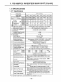
54
1 .9 .1 Specifications . . . . . . . . . . . . . . . . . . . . . . . . . . . . . . . . . . . . . . . . . . . . .
54
1 .10 OPTIONS AND PERIPHERAL UNITS---- . . . . . .--------------
60
1 .10.1 Optional Units . . . . . . . . . . . . . . . . . . . . . . . . . . . . . . . . . . . . . . . . . . . .
60
1 .10.2 Peripheral Units . . . . . . . . . . . . . . . . . . . . . . . . . . . . . . . . . . . . . . . . . .
62
1 .9 SPECIFICATIONS
t- =i
~c
CONTENTS 2 .
Page
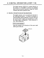
2. DIGITAL OPERATOR (JVOP-114)
. . .. . . . . . . . . . . . . . . . . . . . . . . . . .
2.1 DIGITAL OPERATOR MOUNTING/REMOVING
. . . . . .. . . . . . . . . .
64
64
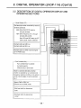
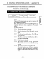
2 .2 DESCRIPTION OF DIGITAL OPERATOR DISPLAY AND OPERATING
SECTIONS . . . . . . . . . . . . . . . . . . . . . . . . . . . . . . . . . . . . . . . . . . . . . . . . 66
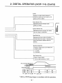
2 .3 FUNCTION/CONSTANT SETTING
.................... . . .. ...
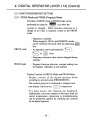
2 .3 .1 DRIVE Mode and PRGM (Program) Mode
2 .3 .2 Constant Reading and Setting
2 .3 .3 Precautions on Constant Setting
68
............ .... . ..
68
. .... . .. . ................... . .
70
. .. . . . . . .. . . . . . . . . . . . . . . . . . .
72
2.4 DIGITAL OPERATOR OPERATION EXAMPLE:
. . .. . ............
2.5 CONSTANT INITIALIZATION AND WRITE-IN PROHIBIT
........
74
76
2 .5 .1 Constant Initialization (Operation to return to factory setting)
....
76
2 .5 .2 Constant Write-in Prohibit (Only constant reading possible)
. ....
77
.... ..... . . ............. . .........
78
2.6 CORRECTIVE FUNCTION
2.6.1 Adjustment of Frequency Setting Value, Output Frequency Bias (No.23)
and Gain (No.22) . . . . . . . . . . . . . . . . . . . . . . . . . . . . . . . . . . . . . . . . . 78
2 .6.2 Calibration of Frequency Meter/Ammeter . . . . . . . . . . . . . . . . . . . . .
80
. . . . . . ......... ... . .. ........ . .. . . . . . ........... .
82
2 .7 MONITOR
2 .7 .1 Typical Monitor Contents and Display (DRIVE= Mode)
2 .7 .2 Monitoring of Fault Contents
......... .
82
. ..... . .. ........... .. . ........
83
CONTENTS 2. (Confd)
Page
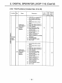
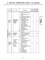
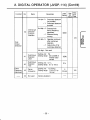
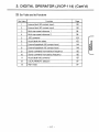
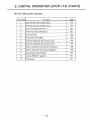
2 .8 FUNCTION/CONSTANT LIST
............ ............... ....
2 .8.1 First Functions (Constant Nos. 00 to 19)
... .............. . ...
2 .8.2 Second Functions (Constant Nos. 20 to 31)
2 .8 .3 Third Functions (Constant Nos. 32 to 59)
88
. . . . . . . . .. . . . . . . . . . .
90
. . .........
95
........ ........... ..... .. .... .........
95
' OPERATION MODE SELECTION
.......... ........... .........
' ALARM RESET FUNCTION SELECTION
' 4-STEP SPEED CHANGE
84
..................
2.9 DESCRIPTION OF FUNCTIONS AND CONSTANTS
' PASSWORD SETTING
84
96
... . ............ .......
97
. . . . . . . . . .. . . . . . . . . . . . . . . . . . . . .. . . . .
98
' S-CURVE PATTERN SELECTION . . . . . . . . . . . . . . . . . . . . . . . . . . . . . . 100
' Wf CHARACTERISTIC SETTING
. . . . . . . . . . . . . . . . . . . . . . . . . . . . . . 102
' JOG OPERATION . . . . . . . . . . . . . . . . . . . . . . . . . . . . . . . . . . . . . . . . . . . . 104
' ACCEUDECEL TIME SETTING . . . . . . . . . . . . . . . . . . . . . . . . . . . . . . . . 105
' LOCAUREMOTE MODE SELECTION
. . . . . . . . . . . . . . . . . . . . . . . . . . 106
' OUTPUT FREQUENCY CONTROL (GAIN/BIAS) . . . . . . . . . . . . . . . . . 107
' ELECTRONIC THERMAL OVERLOAD PROTE=CTION . . . . . . . . . . . . 109
' MULTIFUNCTION ANALOG OUTPUT MONITOR SETTING
' OUTPUT FREQUENCY LIMIT
. . . . . . . 110
. . . . . . . . . . . . . . . . . . . . . . . . . . . . . . . . . 111
' MOTOR STALL PREVENTION FUNCTION
. . . . . . . . . . . . . . . . . . . . . 112
' FULL-RANGE AUTOMATIC TORQUE BOOST
. . . . . . . . . . . . . . . . . . 114
' MULTIFUNCTION CONTACT INPUT FUNCTION SELECTION
. . . . 115
' MULTIFUNCTION ANALOG INPUT FUNCTION SELECTION . . . . . . 119
' MULTIFUNCTION OUTPUT FUNCTION
. . . . . . . . . . . . . . . . . . . . . . . . 121
gm
Ino
CONTENTS 2 . (Cont'd)
Page
' DC INJECTION BRAKING . . . . . . . . . . . . . . . . . . . . . . . . . . . . . . . . . . . . . 123
. . . . . . . . . . . . . . . . . . . . . . . 124
' OVERTORQUE DETECTION FUNCTION
' CARRIER FREQUENCY
. . . . . . . .. . . .
0
.
.
.
.
.
.
.
.
.
.
.
.
.
.
.
.
.
.
.
.
125
' ARBITRARY SPEED DETECTION LEVEL ADJUSTMENT AND
SELECTION . . . . . . . . . . . . . . . . . . . . . . . . . . . . . . . . . . . . . . . . . . . . . . . . . 126
' PROHIBITED FREQUENCY SETTING
. . . . . . . . . . . . . . . . . . . . . . . . . 128
' CONSTANTS EFFECTIVE FOR REDUCTION OF
MACHINE VIBRATION OR SHOCK . . . . . . . . . . . . . . . . . . . . . . . . . . . . 129
' SPEED SEARCH FUNCTION
. . . . . . . . . . . . . . . . . . . . . . . . . . . . . . . . . 130
' CONTINUOUS OPERATION AT MOMENTARY POWER LOSS
'AUTOMATIC RESTART AFTER AFAULT
'ACCEUDECELHOLD COMMAND
2.10 PROTECTIVE FUNCTIONS
. . . . 132
. . . . . .0 . . . . . . . . . . . . . . . . 135
. .0 . . . . . . . . . . . . . . . . . . . . . . . . . . 137
. . . . . . . . . . . . . . . . . . . . . . . . . . . . . . . . 138
2.11 PROTECTIVE FUNCTIONS (WARNINGS)
. . . . . . . . . . . . . . . . . . . 142
WARNING
Twist wires together before inserting in grounding terminal .
CAUTION
Separate motor overcurrent, overload and overheating
protection is required to be provided in accordance with
CANADIAN ELECTRICAL CODE, PART I and NEC .
Use 75 -C copper wires only.
Low voltage terminals shall be wired with Class I Wiring.
When mounting units in an enclosure, remove the top, bottom
and terminal covers.
AVERTISSEMENT
Enroulex les fils ensemble avant de les introduire dans la
borne .
Des tensions subsistent aux bornes des condensateurs pendant
cinq minutes apres I' ouverture de circuit d' entree .
Couper 1' alimentation avant d' entreprendre le depannage du
systeme electrique .
ATTENTION
Une protection distincte contre les surintensites, la surcharge
et la surchaufee de moteur doit etre tburnie conformement
AU CODE CANADIAN DE L' ELECTRICITE, PREMIER
I'ARTIE et LE NATIONAL DE L' ELECTRICITE.
11
DANGER
Voltage are present on capacitors for five minutes after input
circuit is open. Risk of electric shock and/or electrical energyhigh current levels .
WARNING
Disconnect electrical supply before servicing the electrical
system .
Do not change the wiring while power is applied to the
circuit.
Do not check signals during operation.
WARNING
Refer to this manual for connection of circuits and the rating of
auxiliary circuits .
Be sure to ground VS-606PC3 using the ground terminal G.
Connect the motor to output terminals T1, T2, T3 . Connect
an AC power supply to input terminals L I, L2, L3 (for 240 V
single-phase series, connect only to L 1 and L2) .
CAUTION
Separate motor overcurrent, overload and overheating protection
is required to be provided in accordance with CANADIAN
ELECTRICAL CODE, PART I and NEC.
0
CAUTION
All the potentiometers of VS-606PC3 have been adjusted at the
factory. Do not change their settings unnecessarily.
Do not make withstand voltage tests on any part of the VS606PC3 unit. It is electronic equipment using semiconductors
and vulnerable to high voltage .
Make sure to tighten screws on the main circuit and control
circuit terminals . Refer to installation instructions for torque
values . See Par. 1 .5.3 "(5) Wire and terminal screw sizes."
Handle with care so as not to damage the inverter during
transportation .
Do not pick-up by the front cover or the unit cover (plastic
portion) . Use the die-cast portion .
AVERTISSEIVIENT
Des tensions subsistent aux bornes des condensateurs pendant
cinq minutes apres 1' ouverture de circuit d' entree .
Couper 1' alimentation avant d' entreprendre le depannage du
systeme electrique .
ATTENTION
Une protection distincte contre les surintensites, la surcharge et
la surchaufee de moteur doit etre fournie conformement AU
CODE CANADIAN DE L',ELECTRICITE, PREMIER PARTIE
et LE NATIONAL DE L' ELECTRICITF .
1 . VS-606PC3 INVERTER MAIN UNIT
The VS-606PC3 is an ultra-compact, all-digital inverter
which provides low noise operation.
Two types are available : 1) with digital operator or
2) with drive status indicating plate (indicating cover),
and each has two types of enclosures
Enclosed wall-mounted type (NEMA 1)
Water and dust tight type (I1 TEMA4)
The digital operator allows maximum utilization of
the drive by providing access to the inverter's program
constants and operation variables .
The model with the indicating cover provides status
and fault codes while preventing unauthorized access to
the programming constants. It is also useful for those
applications where the programming operator can be
moved from one unit to another.
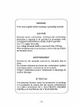
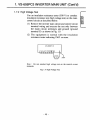
1 . VS-606PC3 INVERTER MAIN UNIT (Cont'd)
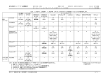
1 .1 PARTS NAMES OF VS-606PC3
With indicating cover
Enclosed wall-mounted type (NEMA1)
PROTECTIVE COVER
(TOP/BOTTOM)
-
FRONT COVER
MTG HOLE
-INDICATING COVER
- DIE-CAST CASE
- TERMINAL COVER
Water and dust tight type (NEMA4)
UNIT COVER
- INDICATING COVER
FRONT COVER
- DIE-CAST CASE
093-167
BOTTOM COVER
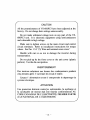
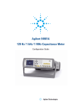
VS-606PC3
digital
indicating
digital
willinbe
the
operator
operator
mounted
unit
cover
INVERTER
(option)
shown
inwhich
place
to the
of
is
MAIN UNIT
OPERATOR
(Cont'd)
i .
With
The
right
the
installed
.
692-530
DIGITAL
JVOP-114
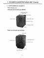
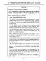
1 . VS-606PC3 INVERTER MAIN UNIT (Cont'd)
1 .2 RECEIVING
This VS-606PC3 has been put through demanding tests
at the factory prior to shipment . After unpacking, check
the following.
Verify the part numbers with the purchase order
sheet and/or packing slip.
Transit damage .
If any part of VS-606PC3 is damaged or missing,
immediately notify the shipper .
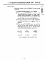
1 .2 .1 Nameplate Data
UL Listed and CSA Certification for Types of 3phase, 230 VAC, 0.25 HP (0.2 kW)
INVERTER
MODEL
INPUT
SPEC .
MODEL
: CI MR-PCU20P2
INPUT
. 3PH 200-230 VAC 50/60 Hz 1 .'7 A
OUTPUT
: 3PH 0-230VAC MAX. 0-1100 Hz
0 .6 WA 0 .25 HP 1 5 A
LOT NO.
L OT NO
SERIAL
NO.
SER NO
\ FILE N0.
SPEC . 20P2N 1
MASS
: E131457
1 .1 kg
"
OUTPUT
SPEC.
MASS
1 . VS-606PO3 INVERTER MAIN UNIT (Confd)
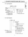
1 .2 .2 Type Designation
CIMR-PC U 2 OP2
Inverter
VS-606PC3
Series
Applicable maximum motor
output
OP1 : 0.13 HP (0.1 kW)
OP2 : 0.25 HP (0.2 kW)
to
3P7 : 5 HP (3 .7 kW)
".P" indicates a decimal point.
Specifications
U : UL Listed and
CSA Certified Component
Voltage class
2 : Three-phase, 230 V
4 : Three-phase, 460 V
B : Single-phase, 240 V
1 .2 .3 Spec Designation
2
OP2
Voltage class --1
2 : Three-phase, 230 V
4 : Three-phase, 460 V
B : Single-phase, 240 V
N 1 B
L Revision mark
Enclosures
1 . NEMA 1
(Enclosed wall-mounted type)
8 : NEMA 4
('Water and dust tight type)
Digital operator provided/not
provided
D : Digital operator provided
N : Digital operator not provided
(with indicating cover)
Applicable maximum motor output
OP1 : 0.13 HP (0.1 kW)
OP2 : 0.25 HP (0.2 kW)
to
3P7 : 5 HP (3.7 kW)
"P Indicates
it declnlal point.
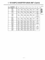
1 . VS-606PC3 INVERTER MAIN UNIT (Confd)
1 .3 DIMENSIONS IN INCHES (mm)
Enclosed wail-mounted type (NEMAi )
U."(0,751
L
0
7-
V V V V ~r
D
n-e DIA
M~
1 . VS-606PC3 INVERTER MAIN UNIT (Conttd)
VS-606PC3
Model CIMR-PCU
W
W1
H
H1
D
d
n-e
20P1
20P2
20P4
4 .13
(105)
366
(93)
5.91
(150)
5.43
(138)
3.94
(100)
0.20
(5)
2-087
(2-22)
20P7
21P5
5.51
(140)
504
(128)
5.91
(150)
5.43
(138)
5.45
(138.5)
0.20
(5)
3-087
(3-22)
22PO
22P2
23P7
5 .51
(140)
4.96
(126)
7.87
(200)
7.32
(186)
6.69
(170)
022
(55)
BOP 1
BOP2
BON
1-0.87
2-1 .10
1-22
C2-28
5.51
(140)
5.04
(128)
5.91
(150)
5.43
(138)
5.45
(138 .5)
0.20
(5)
3-087
(3-22)
BOP?
B 1 P5
5.51
(140)
7.87
(200)
7.32
(186)
6.69
(170)
0.22
(5 .5)
1-0.87
B2P2
B3P7
4 .96
(126)
7.48
(190)
6.89
(175)
7.87
(200)
7.28
(185)
7.48
(190)
0.23
(5 .8)
40P2
40P4
5.51
(140)
40P7
41P5
5.51
(140)
4.96
(126)
7.87
(200)
7 .32
(186)
4.72
(120)
0.22
(5 .5)
42P2
43P7
7.48
(190)
7.87
(200)
7.32
(186)
6.69
(170)
0.22
(5 .5)
7.87
(200)
7.28
(185)
7.48
(190)
0.23
(5 .8)
4 .96
(126)
6 .89
(175)
2-1 .10
1-22}
C2-281
1-0 .87
2-1 .10
1-2
(2-28)
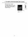
1 . VS-606PC3 INVERTER MAIN UNIT (Contld)
Water and dust tight type (NEMA4)
"M r
6
e
'
88888
DSPL
I1.KavMTaa ,~
0
W1
W
©
I
IJ ~I'IililililiLO
l
D
J
Recommended Cable Lead-In Holes
(Not provided)
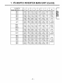
t . VS-606PC3 INVERTER MAIN UNIT (Cont'd)
VS-606PC3
Model CIMR-PCU
W
Wi
H
H1
H2
D
d
n-e
20P 1
20P2
4.45
(113)
366
(93)
6.77
(172)
5.43
(138)
0 .43
(11)
4.07
(103.5)
0.20
(5)
2-0 .91
(2-23)
20P4
20P7
5.83
(148)
5.04
(128)
6.77
(172)
5.43
(138)
0.43
(11)
5.59
(142)
020
3-0 .91
(3-23)
21P5
22P2
5.83
(148)
4.96
(126)
8.94
(227)
7.32
(186)
0.47
(12)
6.83
(173.5)
022
(55)
23P7
7.87
(200)
6.89
(175)
9.06
(230)
BOP 1
BOP2
BON
728
0 .50
7.62
(185) (12.8) (193.5)
023
(5.8)
1-0 .91
2-1 .13
( 1-23l
\ 2-28.6/
5 .83
(148)
5.04
(128)
6 .77
(172)
5.43
(138)
0.43
(11)
5.59
(142)
020
(5)
3-0 .91
(3-23)
BOP7
B1P5
5.83
(148)
4.96
(126)
8.94
(227)
7 .32
(186)
0.47
(12)
6.83
(173.5)
022
(5.5)
82P2
7.87
(200)
6.89
(175)
9.06
(230)
7.28
(185)
(12.8) (193.5)
0.50
7.62
0.23
(5.8)
1-0 .91
2_1 .13
1-23l
(2-28 .6 1
40P2
40P4
5.83
(148)
4.96
(126)
8.94
(227)
7 .32
(186)
0.47
(12)
4.86
(123.5)
022
40P7
41P5
5.83
(148)
4.96
(126)
8.94
(227)
7.32
(186)
0.47
(12)
6.83
(173.5)
022
(5.5)
42P2
43P7
7.87
(200)
6.89
(175)
9.06
(230)
7.28
0.50
7.62
(185) (12 .8) (193.5)
0.23
(5.8)
(5)
(5.5)
t-0.91
2-1 .13
1-23l
(2-28.6'
tuz
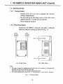
1 . VS-606PC3 INVERTER MAIN UNIT (Cont'd)
1 .4 INSTALLATION
1 .4 .1 Transportation
Handle with care so as not to damage the inverter
during transportation.
Do not pick-up by the front cover or the unit cover
(plastic portion). Use the die-cast portion .
Do not drop the inverter.
1 .4.2 Mounting Space
Install the VS-606PC3 vertically and allow sufficient
space for effective cooling as shown in Fig. 1 .1 .
1 .18 in
(30 mm)
OR MORE
1 .18 in
(30 mm)
OR MORE
3 .94 m (100 mm) OR MORE
3 94 m (100 mm) OR MORE
t-
(a)
Front View
AIR
AIR
(b) Side View
Notes
1 . The space required at top/bottom and both sides are common in enclosed wallmounted type and water and dust tight type .
The inverter shown above is enclosed wall-mounted type .
2. For external dimensions, refer to Par. 1 .3 "Dimensions in inches (mm)" on page 6.
Fig. l .I
Mounting Space:
- 10 -
t . VS-606PO3 INVERTER MAIN UNIT (Confd)
1 .4 .3 Location
Location of the equipment is important to achieve
proper performance and normall operating life. The VS606PC3 units should be installed in areas where the
following conditions exist .
Ambient temperature : +14 to 104 ° F, -10 to +40 °C .
Protected from rain or moisture. (For enclosed wallmounted type)
Protected from oil sprays, splashes .
Protected from direct sunlight. (Avoid using outdoors .)
Protected from corrosive gases or liquids.
Free from airborne dust or metallic particles. (For
enclosed wall-mounted type)
Free from salt spray.
Free from vibration.
Free from magnetic noise . (Example : welding
machines, power devices, etc.)
Protected from high humidity .
Free from combustibles .
cc L_
t.
VS-606PO3 INVERTER MAIN UNIT (Cont'd)
CAUTION
Enclosed wall-mounted type (NEMA1)
When mounting units in an enclosure, remove the top, bottom and
terminal covers, and install a cooling fan or some other means to
cool the air entering into the inverter below 113 ° F (45 °C) .
Water and dust tight type (NEMA4)
Never submerse this model in water.
The models of a forced-air-cooled type are provided with a
cooling fan in the die-cast case. Protect the cooling fan from
moisture . Excessive water splash may reduce the inverter
operating life .
If water splashes on the cooling fan section, keep the cooling
fan operating for approx. 30 minutes in order to dry it. (By
conducting current to the inverter unit, the cooling fan rotates .)
For the cable lead-in section (at the bottom cover), use a cable
gland of a waterproof type . (Products described in pages 14
and 15 are available as options.)
Cable lead-in holes are not provided in the bottom cover .
According to your application, drill holes in the bottom cover .
Refer to pages 8 and 9.
After completion of wiring, mount the front cover and bottom
cover with care . (Pay attention so as not to damage the gasket.)
Since the inverter unit cover is sealed with the die-cast case,
never remove it .
The front cover mounting screws and bottom cover mounting
screws are of stainless . Do not use any other screws than those
attached . (In particular, screws of different length may cause
damage .)
When silicon rubber cement applied to the contacting section of
the front cover and bottom cover for reinforcement of
waterproof performance, use silicon rubber cement with less
gas generated when hardening .
(Recommended : KE-3494 made by SHIN-ETSU CHEMICAL
CO., LTD.)
- 1 2-
1 . VS-606PO3 INVERTER MAIN UNIT (Cont'd)
1 .4.4 Cable Gland
When a cable gland is used for water and dust tight type
(NEMA4) models, pay attention to the following items .
- Use multi-core cable for cable gland. (If more than
two cables are inserted into one cable gland, a gap is
created and may cause leakage.)
- Seal the cable gland with a gasket wichout fail. (A
gasket is attached to the recommended cable gland .)
Cable Gland Mounting Hole (Not Drilled in Bottom Cover)
Dimensions in inches (mm)
VS-606PC3
Model CIMR-PCU
20P 1
20P2
20P4
20P7
21P5
22P2
23P7
BOP 1
BOP2
BOP4
BOP?
B 1 P5
B2P2
40P2
'
43P7
oty-Dia
j
2-0 .91
(2-23)
3-0 .91
(3-23)
1-0.91
2-1 13
1-23
(2-286
3-0 .91
(3-23)
1-091
2-1 13
1-23
(2-286
1-091
2-1 13
1-23
(2-286
1 . VS-606PO3 INVERTER MAIN UNIT (Cont'd)
Recommended cable gland
For cable gland for water and dust tight type (NEMA4)
models, refer to the following YASKAWA code No.
and quantity when you place an order.
VS-606PC3
Model CIMR-PCU ;-----20P 1
20P2
20P4
20P7
21P5
22P2
23P7
Cable Gland
YASKAWA Code No.
Qty
WSZT31002-A
2
WSZ T31002-A
3
WSZT31002-A
1
WSZT31002-B
2
WSZT31002-A
3
WSZT31002-A
1
WSZT31002-B
2
WSZT31002-A
1
WSZT31002-B
2
BOP 1
BOP2
BOP4
BOP7
B 1 P5
B2P2
40P2
40P4
40P9
41P5
42P2
43P7
Notes
1 . Lock nut, gasket and the like requirec for one-hole wiring with
one cable gland are provided .
2. The quantity shown in the above table is the number of cable
glands required for one inverter unit.
1 . VS-606PC3 INVERTER MAIN UN-1T (Cont'd)
bftblb,
Dimensions in inches 'mm;
qqq~FA
B
SW 1
Cmax
D
E:
F
H
SW2
G
WSZT31002-A 1 16
1.29 .5;
;Size PG 16)
057
',14.5)
1 .06
(27,
142
,1 36)
073
1,18 5,
024
; E3)
008
((2',
026
(6.51
1.18
130)
130
;33 ;
WSZT31002-B 140
;Size PG 21,
(35.5)
073
(18.5)
130
; 33,`
157
;40)
089
(225)
024
;61
008
'2',
0.30
(75)
142
(36)
154
(39)
C
Q
CD
LCCKNUT
Specifications
Cable Gland
Applicable cable size
'Tightening torque
WSZT31002-A
0 39 DIA to 0 55 DIA
(10 DIA to 14 DIN
5 to 9 (N-m)
WSZT31002-B
0 .51 DIA to 0 7 DIA`
(13 DIA to 18 DIA)
7.5 to 9 (N-m)
VS-606PO3 INVERTER MAIN UNIT (Cont'd)
1.
1 .5 WIRING
Connect main circuit and control circuit wiring securely
as described in the following.
Use UL Listed and CSA Certified closed-loop (ring) connectors
sized for the wire gauge involved. The connectors are to be
installed using the correct crimp tool specified by the connector
manufacturer.
1 .5 .1 Cover Mounting/Removing and Terminal Position
Enclosed wall-mounted type (NEMA1)
Terminal cover mounting/removing
For removing, press the cover in the direction of D (on
both sides) and, at the same time, lift in the direction of
0. For mounting, reverse the method.
TIMME
o
TERMINAL
' ~\
0
rr °
1 . V$-606PC3 INVERTER MAIN UNIT (Cont'd)
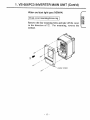
Water and dust tight type (NEMA4)
Front cover mounting/removing
Remove the four mounting bolts and take off the cover
in the direction of U . For mounting, reverse the
method .
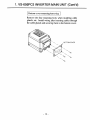
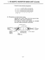
1 . VS-606PC3 INVERTER MAIN UNIT (Cont'd)
Bottom cover mounting/removing
Remove the four mounting bolts when installing cable
glands, etc. Install wiring after inserting cables through
the cable glands and securing them to the bottom cover .
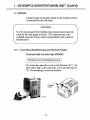
1 . VS-606PC3 INVERTER MAIN UNIT (Cont'd)
Terminal position
Main circuit and control circuit terminal blocks are
shown below. Usually the terminal Nos . are shown on
the terminal No. nameplate .
For some inverters, the terminal Nos. are printed on
the printed board. The location of terminal blocks for
both enclosed wall-mounted type (NEMA 1) and water
and dust tight type (NEMA4) is the same .
The photo shows the enclosed wall-mounted type
(NEMA 1) .
CONTROL CIRCUIT
TERMINAL BLOCK
(M3 .5)
MAIN CIRCUIT
TERMINAL BLOCK
(M4 OR M5)
692-365
GROUNDING\
TERMINAL CHARGE LAMP
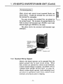
1 .5.2 Standard Wiring Diagram
Models with digital operator can be operated from the
digital operator only by main circuit wiring . When
these models are operated by control circuit terminals,
control constant change is required. For details, refer to
"OPERATION MODE SELECTION" on page 96 .
Models without digital operator (with indicating cover)
are preset in operation mode from control circuit
terminals at the factory prior to shipping .
t . VS-606PC3 INVERTER MAIN UNIT (Confd)
MAIN CIRCUIT
POWER SUPPLY
ONLY TERMINAL L1,
L2 FOR SINGLE-PHASE
POWER SUPPLY
BRAKING RESISTOR ;OPTION)*
MCCB
r---
L1 --o
L2 -~
L3 --o
o
o
o
FORWARD
RUN/STOP
1
I I
I
FAUL T RESET
_XTE NAL
FAULT
I
SPEED SREP
TEP t-0
1
I
4
VS-606PC3
'
I
3
4
I I
i
I
l
5
M ULTIFUNCTION
CONTACT INPUT
cv
I
u iv + iu vI
,
--
4 TO 20 rrA
-
P
P
10
I
I
I I
8
9
MONK ; cJF,
~F
1
>
~
1
roo--~
SHIELDED LEAD
CONNECTION TERMINAL
AIN CI CU T ) WI TH
2c ~~A
RE~f+ l12 v
MASTER REF
E )
4-O0 A E
RE )
(VOLTA
G
6URREN T REF _
'4-20 mA '.2500)
OV
1
J
APALOGOUTPUT
0 TO + 10 VDC
FACTORY SETTING IS
'OUTPUT FREQUENCY"
MULTIFUNCTION
CONTACT OUTPUT
CONTACT CAPACITY
LESS THAN 1 A FOR
250 VAC AND 30 VDC
FACTORY SETTING IS
"FAULT SIGNAL"
FLT
SEQUENCE
COMMON
POWER
f 1
~
J
- _-----
FL T-B
G
VOLUME2
VOLUME 1 '
IM
T3~
1
ANALOG
.0
FREQUEN - ~
CY REF .
T1 o
T2 o
G
1
Y
B2
'
RUN/SOP
MA5 I tt-t
B1/p+
L1
L2
L3
-13
DURING RUN
14
j FREO EN(:Y
7ACx~
AGREEMENT
ANALOG INPUT MODULE
JVOP-1 15 !OPTION
Fig. 1 .2 Standard Wiring Diagram
1
I,
MULTIFUNCTION
PHOTO-COUPLER
OUTPUT : LESS
THAN 48 V 50 mA
1 . LAS-606PC3 INVERTER MAIN UNIT (Contod)
Notes
1.
indicates shielded leads and
1^
gyp twisted-pair shielded leads .
2 . External terminal 10 of + 12 V has maximum output current capacity of 20 mA.
3. Terminal symbols : 0 shows main circuit ; O shows control circuit .
4 . Terminal point 6 (sequence common) is isolated from terminal point 11 (OV) .
* Set thermal overload relay between braking resistor and inverter when using braking
resistor without thermal overload relay (ex. : type ERF-150WJ, option) to protect it
from overheating . Use sequencer to break power supply side on thermal overload
relay trip contact when using braking resistor . Also, when using braking resistor unit
with thermal overload relay (type LKEB, option), use sequencer to break power
supply side on thermal overload relay trip contact .
T Volume 1
: For frequency setting
± Volume 2 : Resistor to reduce the voltage from +12V to +10 V . Considering the
voltage drop by wiring impedance, power supply voltage is set to +12 V .
When volume 2 is not provided
OV ' v
10V (MAX FREQUENCY)
17V
VOLUME 1
Max frequency when turning volume 1 to 80% .
Even if turning more, frequency remains at the
maximum . Even if +12 V loads on terminal 8,
it will not damage the inverter nor affect its
operation.
1 . VS-606PC3 INVERTER MAIN UNIT (Cont'd)
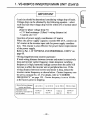
1 .5 .3 Main Circuit
(""Suitable for use on a circuit capable of delivering not more
than 1000 rms symmetrical amperes, 240 V Max." Models with
20P1, 20P2, 20P4, BOPI, BOP2 and BON suffix only.
"Suitable for use on a circuit capable of delivering not more
than 1000 rms symmetrical amperes, 460 V Max." Models with
40P2 and 40P4 suffix only.
"Suitable for use on a circuit capable of delivering not more
than 5000 rms symmetrical amperes, 240V Max." Models with
20P7, 21P5, 22P2, 23P7, BOP7, B 1 P5, E,2P2 and B3P7 suffix
only.
"Suitable for use on a circuit capable of delivering not more
than 5000 rms symmetrical amperes, 460V Max." Models with
40P7, 41P5, 42P2 and 43P7 suffix only.
(1) Main circuit wiring
Connect wiring as shown in Fig. 1 .3.
BRAKING RESISTOR UNIT OR
BRAKING RESISTOR
(BOTH OPTIONAL)
F 1-tW~21
P
-moo}- - ,
B
o
B2
{
B1/(D
~L 1
3-PHASE L 1 ---°
POWER L2 --o0
o :L2
T2
VS-606PC3
SUPPLY L3 __,^0
°. L3
MCCB
ONLY TERMINAL L1, L2
FOR SINGLE-PHASE POWER SUPPLY
Fig. 1 . 3 Main Circuit Wirinig
T 1,°
T3
C'
t
°
o
MOTOR
IM
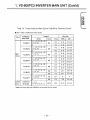
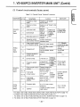
7 . VS-606PC3 INVERTER MAIN UNIT (Cont'd)
(2)
Main circuit terminals
lx~
Table 1 .1 VS-606PC3 Main Circuit Terminals
Terminal
L1
L2
L3
T1
T2
T3
B 1/ p+
B2
Description
Main circuit power input
"L 1 ", "L2" are used for single-phase input
specifcations.
Inverter output
Braking resistor or braking resistor unit
connector (options)
Grounding (ground resistance should be 100
ohms or less)
* Use screw for frame ground .
Main circuit terminal arrangement
3-phase series (all models)
L1
L2
L3 B1/Q
B2
T1
T2
T3
240 V single-phase series
240 V single-phase series
NEMA 1 0.13 to 1 .5 HP (0.1 to 1 .5 kW) 3 and 5 HP (2.2 and 3 .7 kW)
NEMA4 0.13 to 2 HP (0.1 to 1 .5 kW)
L1
L2
B1is B2
T 1 T2 T3
B2
BLANK (Do not use
(3)
L1
L2 B1/ D
T1
T2
T3
Molded-case circuit breaker (MCCB) and Fuse for branch circuit
protection
Be sure to connect MCCBs or Fuses between AC main
circuit power supply and VS-606PC3 input terminals
L1, L2, L3 to protect wiring. Recommended ratings of
MCCB and Fuse are listed in Table 1 .2. The fuses
should be Listed Class RK5 fuses.
When a ground fault interrupter is used, select one
not influenced by high frequency . Setting current
should be 200 mA or more and operating time, 0.1 sec
or more to prevent malfunctions .
(Example) NV series by Mitsubishi Electric Co., Ltd.
(manufactured in and after 1988),
EGSG series by Fuji Electric Co., Ltd .
(manufactured in and after 1984)
-23-
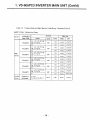
1 . VS-606PC3 INVERTER MAIN UNIT (Cont'd)
Table 1 .2 Branch Circuit Protection
0 230 V Class 3-phase Input Series
VS-606PC3
Model CIMRInverter
Capacity
, ;, , ,
,,
PCU20P , "-Cb'2CP2 PCU2"-L
,
,
.,1-"" 1 20'P7 PCU2 ~P5 PCU22PC PCU22P2 PC''23P7
NEMA 1
NEMA4
0.3
06
1 .1
1 .9
2.5
2.8
4.2
67
03
06
1 1
1 .9
-
42
6.7
Rated Output
NEMA 1
A
Current
NEMA4
28
08
1 5
3
5
6.5
7.3
11
175
0.8
1 .5
3
5
7.3
-
11
175
MCCB or Fuse, Class RK5
3A
5A
5A
10A
20A
20A
20A
WA
I
30A
" 240 V Class Single-phase Input Series
VS-606PC3
Model CIMRInverter
Capacity
PCUBOP 1
0CU80P2
QCUBC~4
PGJB0o7
-'CuB 1 P5
PCUB2P2 pCuB3P7
06
1 1
1 .9
2.5
4.2
6.7
06
1 .1
1 .9
28
4.2
-
WA
NEMA 1
NEMA4
0.3
Rated Output A
Current
NEMA 1
NEMA4
0.8
1 .5
3.0
50
6.5
11 .0
17 .5
0.8
1 5
3.0
5.0
73
110
--
3A
5A
10A
20A
20A
40A
50A
MCCB or Fuse, Class RK5
03
j
460 V Class 3-phase Input Series
9
VS-606PC3
Model CIMRInverter
Capacity
Rated Output
Current
WA
A
MCCB or Fuse, Class RK5
PCU4OP2
PCU40P4
PCU4OP7
PCUA 1 P5
PCU42P2
PCU43P7
08
1 2
2
3
37
6 1
1
1 6
26
4
4 8
8
4A
5A
5A
1 0A
1 0A
20A
F
_
1 . VS-606PC3 INVERTER MAIN UNIT (Confd)
(4)
Surge suppressor
The surge suppressors should be connected to the coils
of control relays, magnetic contactors, magnetic valves,
or magnetic brake used for the VS-606PC3 periphery.
Otherwise, large surge voltage occurs at switching and
may cause devices to be damaged or to malfunction .
Select type from Table 1 .3 .
Table 1 .3 Surge Suppressors
Coils of Magnetic Contactor
and Control Relay
200 V
to
230 V
Large-size
Magnetic
Contactors
Control Relay
MY-2,-3 10MRON)
HH-22, -23 (Fuji`,
MM-2, -4(OMRON)
380 to 460 V Units
* Made by MARCON Electronics
Surge Suppressor*
Model DCR2-
Specifications
Code No
50A 22E
250 VAC
0.5 p F 200 Q
C002417
10A 25C
0.
1 pF VAC
1000
C002482
1000 VDC
05pF 2200
0002630
50D 100B
VS-606PO3 INVERTER MAIN
1 .,
(5)
UNIT (Cont'd)
Wire and terminal screw sizes
Use 600 V vinyl-sheathed lead or equivalent .
Use 75 °C copper wires only.
Low voltage terminals shall be wired with Class I
Wiring.
Table 1 .4 Torque Value and Wire Size for Field Wiring Terminals
" 230 V Class 3-phase Input Series
Circuit
Main
Circuit
VS-606 PC3
; CIMRNode
Sy'oo,
Terminal
PCU20P 1
L1, L2, L3, B
B2, T 1 . T2, T3
M4
PCU20P2
L1, L2, L3, B1 /0,
B2, T1, T2 . T3
M4
PCU20P4
PCU20P7
PCU21 P5
G
G
L1, L2, L3, B1/ p,
B2 . T 1 . T2, T3
PCU22PO
PCU22P2
PCU23P7
Common to
All Models
M4
G
L1, L2, L3, B1/p,
B2, T1, T2, T3
G
L1, L2, L3, B1/p,
13 2, T 1. T2, T3
G
L1, L2, L3, B
Control
Circuit
Screw
B2 . T 1, T2, T3
M4
M4
M4
G
L1, L2, L3, B1
B2, T 1 . T2, T3
M4
G
L1, L2, L3, B
B2, T 1. T2, T3
G
1 ,o 14
FLT A, FLT B. FLT C
M4
M35
Torc;,e
Wire Size
mm z
AWG
143
14-10
2to55
143
14-10
2'o 5 5
143
14-10
2tto55
14,3
14-10
2 ;o 5 5
1413
14-10
2
143
14-10
2 o55
1413
14-10
2to55
14,3
14-10
2
143
14-10
2 ;o55
14,3
12-10
3 5 :o 5 5
14,3
1L-10
2 to 5 5
14,3
12-10
35 - o55
143
12-10
3 5 to 5 5
143
12-10
3 5 to 5 5
143
10
55
143
10
55
0 9, ;
22-14
0 3 to 2
1
" Water and dust tight type (NEMA4', not provided for this model
-
0
;0
55
55
1 . VS-606PO3 INVERTER MAIN UNIT (Contod)
Table 1 .4 Torque Value and Wire Size for Field Wiring Terminals (Cont'd)
" 240 V Class Single-phase Input Series
Circuit
VS-606 PC3
Mood CIMR
PCUBOP 1
PCUBOP2
Main
Circuit
PCUBOP4
PCUBOP7
PCUB 1 P5
PCUB2P2
PCUB3P7'
Control
Circuit
Common to
All Models
Terminal
Symbol
L 1, L2, B 1 / O
T 1, T2, T3
G
L 1, L2, B 1 / O
T 1, T2, T3
G
L 1, L2. B 1 / 0
T 1, T2, T3
G
L 1, L2, B 1 / O
T1,
G T2, T3
, B2,
, B2,
Torque
AWG
mm 2
143
14-10
2 to 5 5
143
14-10
2 to 5 5
143
14-10
2 to 5 .5
143
14-10
2 to 5 5
143
14-10
2 to 5 5
143
14-10
2 to 5 5
143
14-10
2 to 5 5
143
12-10
3 5 to 5 5
143
12-10
35to55
143
12-10
3 5 to 5 5
M5
2 24
10-8
5 5 to 8
M4
M5
143
10-8
5 5 to 8
224
8
8
M4
143
10-8
5 5 to 8
M3 5
0 95
22-14
0 3 to 2
Screw
M4
M4
, B2,
M4
, B2,
L1, L2, 131/9 , B2,
T1, T2, T3
G
L1, L2, 8 1/p , B2,
T 1, T2, T3
G
L1, L2, B1/ 0+, B2,
T 1 . T2, T3
G
1 Lo 14
FLT-A, FLT-B, FLT-C
Wire Size
M4
M4
Water and dust tight type (NEMA4) not provided for this model
t . VS-606PC3 INVERTER MAIN UNIT (Contrd)
Table 1 .4 Torque Value and Wre Size for Field Wring Terminals (Cont'd)
0 460 V Class 3-phase Input Series
Circuit
Main
Circuit
Syr~boi
PCU40P2
L1, L2, L3, B1/3,
B2, T 1, T2, T3
PCU40P4
L1, L2, L3, B1/p+ ,
B2, T1, T2, T3
PCU40P7
PCU41 P5
PCU42P2
PCU43P7
Control
Circuit
Terminal
VS-606 PC3
Mode CIMR-
Common to
All Models
Screw
M4
G
G
L1, L2, L3, B1
B2, T 1, T2, T3
G
L1, L2, 1-3, B1
B2, T 1, T2, T3
G
L1, L2, L3, B
B2, T 1, T2, T3
G
L1, L2, L3, B1/O,
B2, T 1, T2, T3
G
1 to 14
FLT-A, FLT-B, FLT-C
M4
I
M4
M4
M4
M4
M3 5
Wire S ize
Torque
AWG
mm z
143
14-10
2to55
1Q
14-10
2 -.o55
1Q
14-10
2 :055
143
14-10
2 :0 5 5
~3
14-10
2 `.° 5 5
163
14-10
2 :o 5 5
1 ~3
1a-10
2 to 5 5
163
14-10
2 to 5 5
1!3
14-10
2zo55
1 !3
14-10
2 to 5 5
1 ~3
14-10
2 ~° 5 5
1 '-3
12-10
0 ,35
22-14
1
35to55
0 3 to 2
1 . VS-606PO3 INVERTER MAIN UNIT (Contod)
IMPORTANT
Lead size should be determined considering voltage drop of leads .
Voltage drop can be obtained by the following equation : select
such lead size that voltage drop will be within 2% of normal rated
voltage .
phase-to-phase voltage drop (V)
=F X lead resistance ( 0 /km) X wiring, distance (m)
X current (A) X 10
Insertion of power supply coordination AC reactor
When the power supply capacity exceeds 600 kVA, connect an
AC reactor at the inverter input side for power supply coordination. This reactor is also effective for power factor improvement
of the power supply.
Refer to Par. 1 .10 "OPTIONS AND PERIPHERAL UNITS" on
page 60.
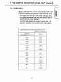
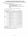
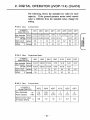
Wiring length between inverter and motor
If total wiring distance between inverter and motor is excessively
long and inverter carrier frequency (main transistor switching
frequency) is high, harmonic leakage current from the cable will
increase to affect the inverter unit or peripheral devices. If the
wiring distance between inverter and motor is long, reduce the
inverter carrier frequency as shown below . Carrier frequency can
be set by constant No . 43 . For details, refer to "CARRIER
FREQUENCY" on page 125 . Carrier frequency is set to 10 kHz
at the factory prior to shipping.
Wiring Distance between
Inverter and Motor
Up to 30 m
up to 50 m
Up to 100 m
100 m or more
Allowable Carrier
Frequency (Constant No
43 set value)
15 kHz or
less (6)
10 kHz or
less (4)
5 kHz or
less (2)
2 5 kHz or
less (1)
1 . VS-606PC3 INVERTER MAIN UNIT (Cont'd)
(6)
Wiring
(a) Main circuit input/output
(1) Phase rotation of input terminals Ll, L2, L3 is
available in either direction, clockwise or
counterclockwise .
(2) When inverter output terminals T1, T2, and T3 are
connected to motor terminals T1, T2, and T3,
respectively, motor rotates counterclockwise, when
viewed from opposite drive end, upon forward run
command. To reverse the .rotation, interchange any
two of the motor leads.
(3) Never connect AC main circuit power supply to
output terminals T1, T2, or T3 . Inverter may be
damaged.
(4) Care should be taken to prevent contact of wiring
leads with the VS-606PG3 cabinet, for a ground
fault or a short-circuit may result.
(5) Insert an L noise filter to the VS-606PG3 output, but
never connect power factor correction capacitor, LC
or RC to VS-606PG3 output.
(6) Be sure to tighten the main circuit terminal screws.
(7) Be sure to separate the main circuit wiring from
inverter and peripheral device control lines .
Otherwise, it may cause the devices to malfunction .
t . VS-606PC3 INVERTER MAIN UNIT (Cont - d)
(b)
Grounding
Ground the casing of the VS-606PC3 using ground
terminal G.
(1) Ground resistance should be 100 SZ or less .
(2) Never ground VS-606PC3 in common with
welding machines, motors, or other largecurrent electrical equipment, or a ground pole .
Run the ground lead in a conduit separate from
leads for large-current electrical equipment.
(3) Use the ground leads which comply with AWG
standards and make the length as short as
possible.
(4) Where several VS-606PC3 units are used side
by side, all the units should be grounded as
shown in (a) or (b) of Fig 1 .4. Do not form a
loop with the ground leads as shown in (c) .
(a)
GOOD
QW 1
LM4
(b) GOOD
(c) POOR
Fig. 1 .4 Grounding of Three VS-6()6PC3 Units
t . VS-606PO3 INVERTER MAIN UNIT (Confd)
1 .5 .4 Control Circuit
CAUTION
Low voltage terminals shall be wired with Class I Wiring.
(1) Control circuit wiring
The control signals are connected by screws. Refer to
Fig. 1 .2 for I/O signals and screw terminal numbers.
The terminal functions shown in the figure indicate
standard setting prior to shipping . Since operation
mode from the digital operator is set for the model with
the digital operator, it is necessary to change the control
constants when operation is performed from the control
circuit terminals . For details, refer to "OPERATION
MODE SELECTION" on page 96 . For the model
without digital operator (with indicating cover),
operation mode from the control circuit terminals is the
standard setting preset at the factory prior to shipping.
i . VS-606PC3 INVERTER MAIN UNIT
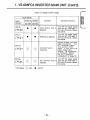
(2)
(Cont"d)
Controrl circuit terminals (factory preset)
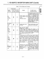
Table 1 .5 Control Circuit Terminal Functions
Classification Te- ;^al
Sequence
Input
Signal
1
Forward run /stop
signal
2
Reverse run/stop
signal
3
Fault reset input
4
5
10
Analog
Input
Signal
8
_
9
11
13
14
Sequence
output
Signal
7
FLT-A
FLT-B
Analog
output
Signall
Signal Name
Funcl ion
Forward run at "closed",
stop at "open"
Reverse run at "closed", stop
I at "open"
Reset at
Multifunction
closed
contact
input
I Fault at
External fault
signals
"closed"
available to
Effective at select"`
Multi-step speed ref . 1
"closed"
Sequence control
Common terminal for
input common terminal se;: #j=u*tw - )ut
Power supply terminal
for frequency setting Speed ref power supply
0 to + 10V/Max. output
frequenc
Frequency ref.
4 to 20 mA/Max . output
fregency
Common terminal for
0V
control circuit
Multifunction photocoupler
output: two
level at set
'L"
Frequency agreed
signals
frequency=output
signal
available to
frequency
select t
Photo-coupler output Common terminal for
I During running
sequence output
Fault signal
contact output
!he ',,rcton as
t,or
-LA
fu #
output
"Closed" between
A and C at "ault
"oxen" between
Fault signal
contact output
common
12
Frequency meter
11
Common
Photo-coupler
insulation input
24 VDC 8 mA
+12 V IAlbwable
current 20 mA max.)
0 to + 10 V
(20kQ)
4 to 20 mA
250
"L" level at run
common
FLT-C
Signal Level
Poss,ole to se:ecl.
function
contact
output
Photo-coupler
output +48 V
50 mA or less
Contact capacity
250 VAC
1 A or less
30 VDC .
1 A or less
B and C a; `aul;
0 to 10 V/max. output
frequency
Possible to select current
meter output
0 to 11 V max.
2 mA or less
* For details, refer to "MULTIFUNCTION CONTACT INPUT FUNCTION SELECTION" on page 115.
r For details, refer to "MULTIFUNCTION OUTPUT FUNCTION" on page 121 .
For details, refer to "MULTIFUNCTION ANALOG OUTPUT MONITOR SETTING" on page 110.
it For details, refer to "MULTIFUNCTION OUTPUT FUNCTION" on page 121 .
-33-
i . VS-606PC3 INVERTER MAIN UNIT (Confd)
Control circuit terminal arrangement
oooo00
8
o
FLT FLT FLT 1
-A -B -C
9
2
10 11
3
4
12
5
13 14
6
7
(3) Precautions on control circuit wiring
Separate the control signal line from power lines .
Otherwise, it may cause a malfunction .
For frequency setting signal (analog), use shielded
lead and conduct termination sufficiently.
SHIELDED SHEATH
r
TO VS-606PC3
SIGNAL
-~
TERMINALS
L
OUTER JACKET
Z5
TO SHIELD ~ ~ WRAP BOTH ENDS
SHEATH
OF SHEATH WITH
TERMINAL
INSULATING TAPE
(TERM. G)
CRIMP
CONNECTION
TO
~ EXTERNAL
CIRCUIT
DO NOT CONNECT
1 . VS-608PC3 INVERTER MAIN UNiI" (Cqnt'd}
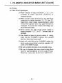
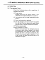
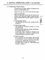
1 .6 OPERATION
1 .6 .1 Pre-operation Check
Check the following items after completion of
installation and wiring
(1) Proper wiring.
Double check that the power supply is not
connected to the output terminals T1, T2 and T3.
(2) No shortcircuit due to wiring contamination (dust,
oil, etc.).
(3) Screws and terminals are tightened.
(4) For safe operation, the motor should be uncoupled
from the load. Pay close attention to output current
when the motor is operated with the load coupled.
(5) Wiring is not grounded.
(6) Run command is not input.
When the forward/reverse run command is input in
the operation mode (factory setting for the model
with indicating cover} from the control circuit
terminal, the motor is activated automatically after
the main circuit power supply is turned on. Turn
on the inverter only after making sure that the run
command is not input.
t . VS-606PC3 INVERTER MAIN UNIT (Cont'd)
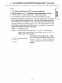
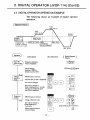
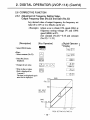
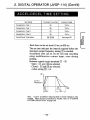
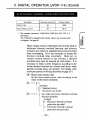
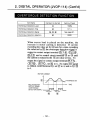
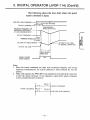
1 .6 .2 Pre-operation Setting
Since the standard inverter models are provided with
the values indicated in Par.2 .8 (see page 84 and
beyond), the digital operator (J VOP-114) must be used
in order to change the constants from the initial values
LU Lilt; VQILIGJ III QLLVIUdllUG WIL.ll Lilt IUdU JPGL111LdLIVIIJ .
(1)
Preset values prior to shipping
The following describes the functions and initial
constant set values which are often used for
operation .
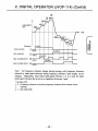
(a) Output frequency and accel/decel time
The maximum output frequency is set to 60 Hz
and accel/decel time to 10 seconds at the factory
prior to shipping. To change the values, refer
to "ACCEL/DECEL TIME SETTING" on
page 105 .
OUTPUT
FREQ.
(Hz)
10 sec
I
DECEL TIME
Fig . 1 .6 Output Frequency and Accel/Decel Time
M h=
u-1g
F.
1 . VS-606PC3 INVERTER MAIN UNIT (Cont'd)
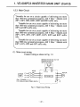
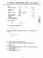
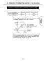
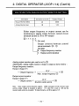
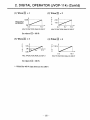
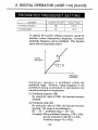
(b)
Frequency setting signal and
output frequency
Fig. 1 .7 shows the inverter
output frequency change as
a result of changes of the
input voltage signal at
terminal ® or current at
terminal ~9 .
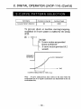
(c) V/f characteristics
Fig. 1 .8 shows the output
voltage for inverter output
frequency. When its characteristic (max . voltage / frequency) differs from that of
the optimum motor, refer to
"V/f CHARACTERISTIC
SETTING" on page 102.
60
230
OUTPUT
FREQ.
(Hz )
i
i
i
15,/
0 0.25
i
10V
FREQ. SETTING VOLTAGE (V)
Fig. 1 .7 Frequency Setting Signal
and Output Frequency
(2)
OUTPUT
VOLTAGE
,
0 1 5
60
OUTPUT FREQ (Hz)
Note ; For 460 V class, the value is
twice that of 230 V class.
Fig . 1 .8 V/f Characteristics
Motor rated current setting
Since the inverter is provided with an electronic
thermal overload to protect the motor from
overheating, the motor rated current should be
programmed into constant (No .19). YASKAWA
standard 4-pole motor current value is set as the
initial value . For details, refer to "ELECTRONIC
THERMAL OVERLOAD PROTECTION" on
page 109.
Note : Provide a thermal overload relay or thermal protector
when more than one motors are operated simultaneously .
t . VS-606PC3 INVERTER MAIN UNIT (Coht"d)
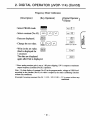
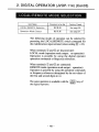
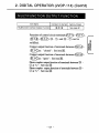
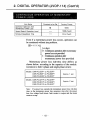
1 .6 .3 Test Run Method
The inverter can be operated i n the following two ways.
The model with digital operator is set to "OPERATION
MODE BY DIGITAL OPERATOR" and the model
without digital operator (with indicating cover) is set to
Vr Li~ti 1 lkJll lV1kJliju- r'itkjj.Vl %..kill 1 1Xkjl_j
TERMINAL" prior to shipping.
V1 1
Run by digital operator
(Standard setting of model with
digital operator)
Run by control circuit terminal input
(Standard setting of model with
indicating cover)
This method is to operate the
inverter by using the RUN (run
command) key, etc . of the digital
operator.
Since this operation mode is
set at the factory prior to shipping,
operation can be performed only
by main circuit wiring .
For details of the operation
method, refer to Section 2
"DIGITAL OPERATOR" beginning on page 64.
This method is to operate the
inverter by frequency setter or
operation switch connected to the
control circuit terminal.
To perform operation by
control circuit terminal input of the
model with digital operator, change
the operation mode to
"OPERATION FROM CONTROL
CIRCUIT TERMINAL" (No .
01=0000).
POWER
SUPPLY
-o
INVERTER
606PC3
MOTOR
POWER
SUPPLY
IM
FWD SIGNAL
REV SIGNAL
FREQ.
SETTER
INVERTER
606PC3
MOTOR
IM
Ujz
92
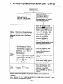
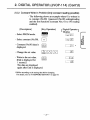
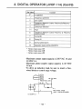
1 . VS-606P03 INVERTER MAIN' UNIT (Gont'd)
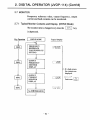
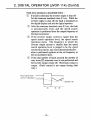
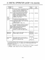
POWER ON
OPERATION BY
CONTROL CIRCUIT
TERMINAL INPUT
(Standard setting of models
with indicating cover)
OPERATION BY
DIGITAL OPERATOR
" Enter the program mode
(depress
Opera- Need not to change the mode
since operation mode by digs
tion
Method operator is set at the factory.
Selection
Select frequency reference
value display
depressing
Opera-
tion
by
key on
DS P L
digital operator.
- Depress
ENTER key after setting
frequency value by using
or
Depress
Stopping
CU U U,~
- Depress
gT
R
N
" STOP
key.
E,
key.
p q I V E key) and set
No. 01 data to 0000 by using
C) ,
or RE ET key.
Then depress ENA ER key.
Enter the drive mode
(depress p R I V E key).
After above operation,
command from control circuit
terminal can be received.*
Turn the frequency setter
knob to the left to decrease
value fully . (frequency
reference=0)
Turn ON FWD or REV run
signal .
- Turn the frequency setter
knob slowly to the right to
increase value fully.
Turn the frequency setter
knob slowly to the left to
decrease value fully.
Turn OFF FWD or REV run
signal.
key.
*Models' without digital operator (models with indicating cover) creed not this
operation .
Note : Refer to Par. 2.4 "DIGITAL OPERATOR OPERATION EXAMPLE" (page
74) for details of digital operator operation.
-40-
1 . VS-606PO3 INVERTER MAIN
UNIT (Cont'd)
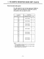
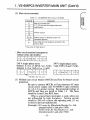
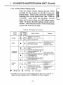
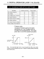
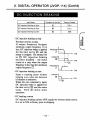
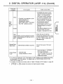
1 .6 .4 Inverter Status Display LEDs
With the model without digital operator, LEDs
provided for the inverter are of help to know the
inverter status . These LEDs can be seen through the
indicating cover on the inverter front side . There are
two LEDs : green (DS 1) and red (DS2). Inverter
status can be seen by these two LED lighting modes.
Table 1 .6 shows the LED lighting modes and the
contents. Check that the inverter is in the normal status
at power ON in the test run stage.
Table 1 .6 LED Display and Contents
Inverter
Status
LED Display
DS 1
DS2
(GR)
(RD)
Normal
Alarm
Protective
operation
"
;0
"
"
%I/
C
,~
~
~
"
-O
l~
,
-10 ;
"
"
Inverter
fault
LED light off,C :
Display Conten:s
Remarks
Operation ready (during
STOP)
During normal RUN
Undervoltage (UV), external
B.B, while stopped.
Automatic recovery
by protective
operation release
Inverter external fault (EF is
input.)
Overload protection such as
inverter overload (00, fin
overheat, etc.
Voltage protection such as
overvoltage (OV),
undervoltage (UV)
Overcurrent protection (OC)
Ground fault (GF)
Can be reset after
removing the cause
of fault.
Digital hardware memory fault Cannot be reset.*
(Replace the
(CPF)
inverter.)
Hardware fault such as
Cannot be reset.
control power supply fault,
(Replace the
CPU runaway, etc.
inverter.)
LED blink,
- C~; : LED light .
* By initializing control constants using the digital operator, errors may be released . For
details of constant initialization, refer to "PASSWORD SETTING" on page 95.
M v,
1, VS-606PO3 INVERTER MAIN UNIT (Cont'd)
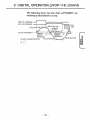
1 .6.5
Digital Operator Display
When the inverter power supply is turned ON for the
first time, the digital operator displays as shown below .
If an alarm is displayed, refer to Par . 1 .8 "FAULT
DISPLAY AND TROUBLESHOOTING" on page 46
to remove the factor. For details of the digital operator
display, refer to Par. 2.2 "DESCRIPTION OF
DIGITAL OPERATOR DISPI.AY AND OPERATING
SECTIONS" on page 66. (In this paragraph, the status
is where no command is input to the inverter).
0 Drive mode display (DRIVE)
Lights .
0 Rotating direction display
(FWD) : Lights.
(REV) : Extinguished .
~3 REMOTE mode display
(REMOTE SEQ, REF)
Extinguished .
® During RUN display (RUN)
Extinguished .
C5) During STOP display (STOP)
Lights .
CO 7-segment LED display
(5 digits)
Output frequency reference
set value
r DRIVE
GWD
O
I~ [
II
III
O
~W
y
W
1
W
1-1
I
W W
1-1 . ii I
~SPL
IF A
-1
L
RUN
?'
'FEHATOR
T
5,
'
I
I ,
IH
ENTER
REV~ ~ESET
__
J_
4
W
U
DRi vE
[EMOTE
i
REV rREMOTE" SEQ " REF "
STOP
~ ; ;' I
Ii l ' I
~i,
_ _ JVOP-
;s;
1 . VS-606PC3 INVERTER MAIN UNIT (Cont'd)
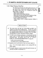
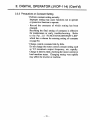
1 .6 .6 Check Points at Test Run
The following describes the check points at test run . If
any fault occurs, recheck the wiring and load status .
For details, refer to Par. 1 .8 .3 "Corrective Action for
Motor Faults" on page 52.
Motor rotates smoothly.
Motor rotates in the proper direction .
Motor does not have any abnormal vibration or beat.
Acceleration or deceleration goes smoothly .
Current suitable for load flows .
Status display LEDs or digital operator display is
proper.
PRECAUTIONS
(1) The motor does not start up if both FWD and REV run
signals are turned ON simultaneous]: y. If they are turned
ON simultaneously during run, the motor stops according to
the stopping method selection of constant (No.01) 3rd digit.
(Deceleration to a stop is selected for factory setting.)
(2) If a fault occurs during acceleration or deceleration and the
motor coasts to a stop, check the motor stop and then the
following items . For details, refer to Par . 1 .8 "FAULT
DISPLAY AND TROUBLESHOOTING" on page 46.
Load is not excessively large.
Accel/decel time is long enough for load.
(3) Resetting must be performed by fault reset input signal (or
key of the digital operator) or by turning OFF the
power supply .
(4) If an input contactor is used to start and stop the inverter, the
maximum number of starts/hour is 1 .
RESET
t . VS-606PC3 INVERTER MAIN UNIT (Cont'd)
1 .7 MAINTENANCE
1 .7 .1 Periodical Inspection
VS-606PC3 requires very few routine checks. It will
function longer if it is kept clean, cool and dry, while
observing the precautions listed in "Location" (Par.
1 .4.3) . Check for tightness o~' electrical connections,
discoloration or other signs of overheating . Use
Table 1 .7 as the inspection guide . Before servicing,
turn OFF AC main circuit power and be sure that
CHARGE lamp is OFF.
Table 1 .7 Periodical Inspection
Component
External
Terminals, Unit
Mounting Bolts,
Connectors, etc.
Cooling Fins
Panted Circuit
Board
Check
Corrective Acton
Loosened screws
Tighten
Loosened connectors
Tighten
Build-up of dust or dirt
Accumulation of conductive
dust or oil mist
Blow with dry compressed air
of 39 .2 x104 to 58 .8 x 104 Pa
[5'7 to 85 psi (4 to 6 kg - cm2~]
pressure .
Blow with dry compressed air
of 39.2 X10⁴ to 58.8 x 10 1-Pa
(5'7 to 85 psi (4 to 6 kg - cm2)]
pressure .
If dust and oil cannot be
removed, replace the inverter
unit .
Cooling Fan
Abnormal noise or vibration.
Whether the cumulative
operation time exceeds
20,000 hours or not .
R
Replace the inverter unit .
Power Elements,
Smoothing
Capacitor
Abnormal odor
Replace the inverter unit.
Note Do not remove the front cover of enclosed wall-mounted, type (NENIA l ) or the unit cover of
water and dust tight type (NEMA4), or failure may occur
1 . VS-606PC3 INVERTER MAIN UNIT (Confd)
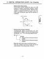
1 .7 .2 High Voltage Test
Use an insulation resistance tester (500 V) to conduct
insulation resistance test (high voltage test) on the main
control circuit as described below .
(1) Remove the inverter main circuit and control circuit
terminal wiring and execute the test only between
the main circuit terminals and ground (ground
terminal G) as shown in Fig . 1 .9 .
(2) The equipment is normal with the insulation
resistance tester indicating 1 M fl or more.
VS-606P 13
1-
L 1 L2 L3 T 1 T2T3 W'B2
Note : Do not conduct high voltage test on the control circuit
terminals .
Fig. 1 .9 High Voltage Test
,
LUZ
1 . VS-606PC3 INVERTER MAIN UNIT (Cont'd)
1 .8 FAULT DISPLAY AND TROUBLESHOOTING
If a fault occurs and the inverter functions are lost,
check for the causes and provide proper corrective
actions, referring to the following checking method.
Contact your YASKAWA representative if any fault
other than described below occurs, if the inverter itself
malfunctions, if any parts are damaged, or if you have
any other problems . A list of the YASKAWA
representatives is available on the last page .
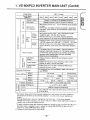
1 .8 .1 Checking of Causes
The inverter has protective functions to protect it from
faults such as overcurrent or overvoltage . If a fault
occurs, the protective functions operate to shut off the
inverter output and the motor coasts to a stop. At the
same time, the fault contact signal is output.
When the protective functions operate in models
with indicating cover, the digital display unit displays a
fault shown in Table 1 .8 . Also when the digital
operator is used, the fault display is provided.
Operation can be restarted by turning ON the
fault reset input signal (or RESET
=' key of the digital
operator) or turning OFF the power supply and ON
again.
E
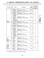
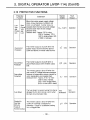
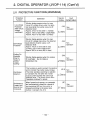
1 . VS-606PC3 INVERTER MAIN UNIT (Gontd)
'
Table 1 .8 Fault Display and Contents
/0-
cc t_
Fault Display
Digital
Operator
(Overcurrent)
Inverter LED Display*
pS1 (GR)
DS2 (RD)
`"
-' -
;
~;
C1 L
GF (Ground
Fault)
OV
Main
Circuit
Overvoltage)
-0-
I
.
_'r,'_
Uu
UV
(Main
Circuit
Undervoltage)
OH
(Cooling Fm
Overheat)
Contents
O~
C
Cause/
Possible
Corrective
Actions
The following causes can be
considered : inverter output side
short-circuit, excessive load
Inverter output current inertia ( J ), excessively short
exceeds 200% of rated setting of accel/decel time,
[constant (No . 09 to 12)] special
current .
motor use, motor start during
(Momentary action)
coasting, start of motor with
larger capacity than inverter,
inverter output side magnetic
contactor ON/OFF.
Reset after finding the cause.
Inverter output side is
grounded.
Check that the motor or load
side wring is not grounded .
Main circuit DC voltage
exceeds 410 V or mcxe
for 230 V class, 820 V Decel time setting is not
or more for 460 V class sufficient. [constant (No . 10,
because of excessive 12)] or minus load (cranes, etc.)
is decreasing . Increase decel
from n motore(Exceeds time or connect a braking
overvoltage protection resistor (option) .
level.)
Undervoltage occurred
is entered . [Main circuit
DC voltage becomes
approx 210 V or less
(230 V class 3-phase'),
170 V or less 1240 V
class single-phase) or
420 V or less (460 V
class 3-phase)).
Input power supply voltage is
reduced, phases are opened
or momentary power loss
occurs, etc Check the power
supply voltage, or check that
main circuit power supply
wring is connected properly
or terminal screws are
tightened well.
Temperature rise caused
by inverter overload
operation, or intake air
temperature rise.
Cooling fan r/mln is
decreased
Load is too large, V/f
characteristics are not proper,
setting time is too short or
intake
load
size, V/f set value [constant
(No 02 to 08)) or intake air
temperature Check the cooling
fan
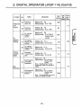
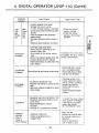
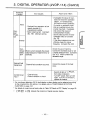
1, VS-606PC3 INVERTER MAIN UNIT (Cont'd)
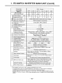
Table 1 .8 Fault Display and Contents (Cont'd)
Fault Display
Digital
Operator
OL 1
(Motor
Overload)
Inverter LED Display*
DS 1(GR)
_
i :# i
,~.
2'
OL3 T
(Overtorque
Detection)
EF3, 4, 5 $
(External
Fault)
EF3
O~
o
"'
C
~~
Digital display
is extinguished .
'
Motor overload protection operates because
of electronic thermal
overload .
Correct load size, operation
pattern or V/f set value
[constant (No . 02 to 08)] .
Set the rated current value
described in the motor
nameplate to constant (No .
19).
Inverter overload
protection operates
because of electronic
thermal overload.
Correct load size, operation
pattern or V/f set value
[constant (No. 02 to 08)] .
Recheck the inverter capacity.
Motor current exceed- Check the machine using
ing set value is applied status and remove the cause.
because of machine Or increase the set value up
fault or overload .
allowable
le
valuehe[constant (No.
Inverter accepts
external fault input from
external circuit .
r_ ',,
CPF#
(Control FunctionFault)
Possible Cause/
Corrective Actions
DS2 (RD)
"'- '
OL2
(Inverter
Overload)
Contents
O'
Check the external circuitry
(sequence) .
Turn OFF
one and tpo
ten turn it ON
Inveter control
again. Or initialize the control
functions are broke,) constant by using the digital
down.
operator . If the fault still
exists, replace the inverter .
Main circuit fuse is
blown . (for 460 V
class only)
Replace the inverter
-Control power supply
fault
Hardware fault
* LED display -'U: light
C - blink
" light off
For OL3 (overtorque detection), fault display or alarm display can be selected according to the
constant (No.37) setting. For details, refer to "OVERTORQUE DETECTION FUNCTION" on
page 124 .
EF3 shows external fault input from multifunction contanct input terminal (3), EF4 from terminal
40 and EF5 from terminal ®.
9 For details of CPF (control function faults), refer to Table 19, "Details of CPF Display" .
t
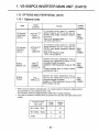
1 . VS-606PO3 INVERTER MAIN UNIT (Contld)
Table 1 .9 Details of CPF D splay
cc f-
Fault Display
Inverter LED Display*
Digital
Operator
CPF-00
I
P11:
""
IJ
~1
CPF-01
,'-
1-1
;
CPF-04
i iii C'-;
CPF-05
'-'
* LED display
Contents
Corrective Actions
DS 1 (GR)
DS2 (RD)
40
40
Initial memory fault is
detected .
Turn OFF the power supply
once and turn it ON again If
the fault still exists, replace
the inverter.
"
"
ROM fault is detected .
Turn OFF the power supply
once and turn it ON again. If
the fault still exists, replace
the inverter .
Constant fault is
detected .
Record all data, and then
make initialization . Turn
OFF the power supply
once and turn it ON
again . If the fault still
exists, replace the
inverter. For initialization
of constants, refer to
Par . 2.5 .1 "Constant
Initialization" on page 76.
- ^-
"
-0-
- 0-
- .,'-
~J:
",
light
IVP
LUZ
~--21Z
Turn OFF the power supply
AD converter fault is once and turn it ON again. If
the fault still exists, replace
detected .
the inverter .
40 : light off
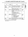
1 . VS-606PC3 INVERTER MAIN UNIT (Cont"d)
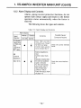
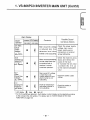
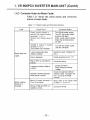
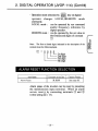
1 .8 .2 Alarm Display and Contents
Alarms, among inverter protective functions, do not
operate fault contact output and returns to the former
operation status automatically when the factor is
removed .
The following shows the types and contents .
Table 1 .10 Alarm Display and Contents
Alarm Display
Digital
Operator
EF (Simultaneous Input
of FWD and
REV
Commands
Inverter LED Display*
DS 1 (GR,`
DS2 ;RD;
Both FWD and REV
commands are "closed"
for 500 ms or larger .
Inverter stops accordmg to constant No. 01 .
"
blinks .
BB
(External
Baseblock')
blinks.
®
Contents
~
External baseblock is
input.
Inverter output shuts
off .
;Operation restarts when
the external baseblock
signal is removed .
For the external baseblock signal, refer to
"MULTIFUNCTION
CONTACT INPUT
FUNCTION SELECTION"
on page 115
Possible Cause/
Corrective Actions
Check the control interface
circuit.
Check the control interface
circuit.
1 . VS-606PC3 INVERTER MAIN UNIT (Cont'd)
Alarm Display
Digital
Operator
UV (Main
Circuit
Undervoltage)
Inverter LED Display*
DS 1(GR) DS2 (RD)
4111111
blinks .
OL3
(Overtorque
Detection) fi
3blinks.
0V
(Main
Circuit Over
voltage)
oru blinks .
OH
(Cooling Fin
Overheat)
oH blinks .
O
C
la x
,,,
41)
/ 1%
Contents
Main circuit DC voltage
is reduced less than
detection level when
inverter is not outputting .
Possible Cause/
Corrective Actions
Check the power supply
voltage, main circuit
power supply wiring
connection or terminal
screw tightening.
Check the machine using
Motor current exceeding status and remove the
the set value flows dUE'
cause of the fault.
to machine fault or
Or increase the set value
overload. Inverter
[constant (No 41)] up
continues operation.
to the machine allowable
value
C
Main circuit DC voltage
is more than overvoltage detection level
when inverter is not
outputting .
Check the power supply
~
/1\
Intake
temperature
when
s
not outputting
Check the intake air
temperature.
voltage .
* LED display C : blink " light off
* For OL3 (overtorque detection), fault display or alarm display can be selected according
to the constant (No 40) setting. For details, refer to "OVERTORQUE DETECTION
FUNCTION" on page 124
1 . VS-606PC3 INVERTER MAIN UN IT (Cont'd)
1 .8 .3 Corrective Action for Motor Faults
Table 1 .11 shows the check points and corrective
actions of motor faults .
Table 1 .11 Motor Faults and Corrective Actions
Fault
Motor does not
rotate .
Check Point
Corrective Action
Power supply voltage is
applied to power supply
terminals L 1, L2, L3
(Check that charge lamp is
ON .)
Turn ON the power supply.
Turn OFF the power supply
and then ON again .
Check power supply voltage.
Check that terminal screws
are tight.
Voltage is output to output
terminals T1, T2, T3
(Use rectifier type voltmeter.)
. Turn OFF the power supply
and then ON again.
Load is excessively large .
(Motor is locked .)
Reduce the load. (Release the
lock.)
Fault is displayed.
Check according to Par. 1 .7 1
FWD or REV run command is
entered.
Correct the wring.
Frequency setting voltage is
entered.
Operation (method selection)
mode setting is proper
Motor rotating
direction is
reversed .
Correct the wring.
Check frequency setting
voltage
Check the operation method
selection mode [constant (No.
01)] by using the digital
operator
Wiring of output terminals T1, Match them to the phase order
T2 ana T3 is correct .
of motor T1, T2 and T3
Wiring of FWD and REV run
signals is correct.
Correct the wiring
1 . VS-606PC3 INVERTER MAIN UNIT (Cont 1 d)
Table 1 .11 Motor Faults and CorrectiVE. Actions (Cont'd)
Check Point
Fault
Motor rotates but
variable speed is
not available.
Motor r/min is too
high (low).
Corrective Action
Wiring of frequency setting
circuit is correct.
Correct the wiring.
Operation (method selection)
mode setting is correct.
Check operation method
;;election mode [constant (No.
01)) by digital operator .
Load is not excessively large.
Reduce the load.
Motor ratings (number of
poles, voltage) are proper .
Check the specifications and
nameplate.
Maximum frequency set value
is correct.
Check the maximum frequency
set value (constant (No.02))
Voltage between motor terminals
is not excessively reduced. (Use
rectifier type voltage.)
check V/f characteristic set
value [constant (No 02 to 08)).
Load is not excessively large
Motor r/min is not
stable duing
operation*
'
Load variation is not
excessively large.
Reduce the load .
Reduce the load variation
Increase the inverter or motor
capacity.
3-phase power supply is used
There is no open phase
Reconnect properly to prevent
open phase.
Single-phase power supply is
Connect an AC reactor to the
used.
power supply.
* Because of motor and load (geared machine) characteristics, motor r/min becomes
unstable or motor current apples . To correct these problems, changing the inverter
control constants may be effective Refer to "CONSTANTS EFFECTIVE FOR
REDUCTION OF MACHINE VIBRATION OR SHOCK" on page 129 for details of control
constants to be changed.
1 . VS-606PC3 INVERTER MAIN UNIT (Cont'd)
1 .9
SPECIFICATIONS
1 .9 .1
Specifications
Voltage Class
Inverter Model
CIMR-PCU
Max Aoplicable Motor
Output
HP (kW) *
Inverter
Capacity
a
a
`n
o
a
kVA
Rated Output
Current
A
230 V 3-phase
20P 1
NEMA4
NEMA 1
NEMA4
Max. Output Voltage
V
3
1 5
21P5
22PO
22P2
23P7
1',075)
1 ;075)
15(15)
20(15)
20(20)
3(22)
5(37)
1 9
2.5
2.8
2.8
42
6.7
65
73
11
175
1 9
5
3
-
3(22)
5(37)
42
6.7
400 Hz (available with constant setting)
3-phase 200 to 230 V, 50/60 Hz
+10%
± 596
Sine wave PWM
0.1 to 400Hz
Digital command ' 0 01'6 (+ 14 to 104° F, -10 to +40r- ),
Analog command : 0.196 (77±50° F, 25f 10,C)
Digital operator reference . 0.1 Hz,
Analog reperence 0 06/60 Hz
0.1 Hz
Frequency Setting Resolution
Output Frequency Resolution
15096 rated output current for one minute
0 to 10 VDC (20k0), 4 to 20mA (2500)
Overload Capacity
Frequency Setting Signal
V/f Characteristic
-
5
7.3
11
17.5
3-phase, 200 to 23C V (proportional to input voltage)
Allowable Frequency
Fluctuation
Approx Braking
Torque t
NEW
NEMA4
Stall Prevention Level
Instantaneous Overcurrent
Overload
Ground Fault
Motor Overload Protection
Overvoltage
Undervoltage
6
1 .1
0.6
1 5
20P7
Allowable Voltage Fluctuation
Accel/Decel Time
a.
08
08
Rated Input Voltage and
Frequency
Frequency Accuracy
(Temperature Change)
0
0 .3
Max. Output Frequency Hz
Frequency Control Range
v
20P4
NEMA 1 013 (01) 025 (0 2) 075 (04)
NEMA4 013(01) 025(02) 075(04)
NEW
1 .1
0.3
06
Control Method
U
20P2
Momentary Power Loss
Cooling Fin Overheat
Power Charge Indication
0.1 to 600 sec (accel/decel time set independently)
15096
15096
10096
5096
10096
2096
Possible to set any of V/f pattern
2096
2096
Possible to set operating current
Motor coasts to a stop at approx. 2i%% , of inverter rated
current.
Motor coasts to a stop afi er 1 minute at approx. 15096 of
inverter rated output current
Protected by electronic circuit
Electronic thermal overload relay
Motor coasts to a stop if main circuit DC voltage exceeds
410 VDC
Activated when DC voltage drops below 210 VDC
Stops if power loss is 15 ms or longer (preset prior to shipping) (operation can automatically restart after recovery from
momentary power loss of up to approx 2 seconds) I
Protected by thermoswitch (only for units with fan)
Charge lamp stays ON until main circuit DC voltage drops
below 50 V
* Our standard 4-pole motor is used to determine max applicable motor output
-54-
1 . VS-606PO3 INVERTER MAIN UNIT
Voltage Class
Inverter Model
-PCU
230 V 3-phase
20P 1
Operation Signal_
Fault Reset
a
Multifunction
Input Selection
-
cn
C
C
CL
o
o
Operation
State
o
12
Photocoupler
Output
Contact
Output
o
Built-in Function
LED Status
Display
>11
o°
o
'-
Digital Operator
Analog Output
Monitor
Protective Configuration
Cooling Method
Mass
Ib (kg)
o
5; c
w v Vibration
20P4
20P7
21P5
22PO
22P2
23P7
Forward run/reverse run by separate commands
Releases protectior while the function is operating
Multifunction contact input 3 of the following signals available
to select .
External fault, muiispeed command, jog operation, accel/decel
time select, 3-wire'. sequence, external baseblock, speed search
command
Multifunction contact output - two of the following signals
available to select (48 VDC, 50 mA or less)
(During running output, zero speed, frequency agreement ,
output frequency ? set value, during overtorque detection, etc )
Possible to select these functions as multifunction outputs
1 NO/NC contact output (250 VAC 1 A, 30 VDC 1 A or less)
(During running output, zero speed, frequency agreement ,
output frequency z set value, during overtorque detection,
et c )
The following setting-up is available . frequency reference
bias/gain, upper/lower frequency limit. DC injection braking
current/time at starting/stopping, full-automatic torque boost,
frequency meter calibrating gain, fault retry, prohibited
frequency, S-curve accel/decel .
Displays contents at RUN/ STOP and protective function
operation.
Displays set frequency, output frequency, output current,
direction of rotat;on, and the fault status.
Analog output (0 to 10 VDC)
frequency or output current
Possible to select output
Enclosed wall-mounted type (NEMA 1), water and dust tight
type (NEMA4)
Serf-cooling
Forced-cooling
NEMA4
Forced
Self-cooling
Forced-cooling
cooling
NEMA4
Storage Temperature #
Humidity
20P2
NEW 1
Ambient Temperature
E~
o
(Cont'd)
440
66(3)
88 (4)
8.8 (4)
+14 to 104°F (--10 to +409C) (not frozen)
132 (6)
-4 to 140°F (-20 to +60°C)
9096 RH or less(non-condensing)
Up to 9 8 m/s2 (1 G) at less than 20 Hz, Up to 2 m/s2 (0 2 G)
at 20 to 50 Hz
The values show a short-term average deceleration torque when the motor single-unit
decelerates from 60 Hz at the shortest distance It is not a continuous regenerative
torque .
Average deceleration torque is changed by the motor loss, If the motor operates
exceeding the base frequency, this value is reduced When a large regenerative torque is
needed, use an optional braking resistor .
t To select "automatic restart after momentary power loss," set the 1st digit of constant (No 46) to "1 "
Automatic restart is available for up to 1 second for models CIMR-PCU20P7 or less or up to 2
seconds for models CIMR-PCU21 P5 or greater
# Temperature during shipping (for short period)
t
1 . VS-606PC3 INVERTER MAIN UNIT (Cont'd)
Voltage Class
Inverter Model
CINR-PCU
Max. Applicable Motor
Output
HP (kW)*
Inverter
Capacity
a
o c)
240 V Single-phase
NEMA1
NEMA4
NEMA 1
KVA NEMA4
Rated Output
Current
NEMA 1
A NEMA4
Max. Output Voltage
V
BOP2
BOP4
BOP7
B 1 P5
B2P2
B3P7*
013(01)
025(02)
075(04)
1(075)
15 (15)
3(22)
5 (37)
0 .3
06
1 .1
1 .9
25
4.2
67
1 5
30
013(01)
03
0.8
08
025 (02)
0.6
Rated Input Voltage ar;d
Frequency
o
Al;owable Voltage Fluctuation
Allowab;e Frequency Fluctuation,
Cor"trol Method
Frequency Control Range
Frequency Accuracy
'Tem erasure Chan e
o
o
v
Output Frequency Resolution
Overload Capacity
Frequency Setting Signal
Accel/Decel Time
Approx Brak;^g
Torque f
V/f Characterist'.c
110
110
Motor Overload Protection
Overvoltage
Undervoltage
Momentary Power Loss
Cooling Fin Overheat
Power Charge Indication
-
175
Single-phase ?_00 to 240 V, 50/60 Hz
±110%
+ 5%
Sane wave PWM
0. 1 to 400Hz
Digital command : 0019E, (+14 to 104° F, -10 to +401C),
Analog command . 0 1% (77±50° F, 25± 10V
Digital operator reference - 0.1 Hz,
Analog reference : 0 06/60 Hz
0 1Hz
150% rated output current for one minute
0 to 10 VDC (20k Q '/, 4 to 20mA (2500 )
150%
Ground Fault
6-
65
42
NEMA4
Overload
o
5.0
2.8
3(22)
0.1 to 600 sec (acce i /decel time set independently)
150%
100%
50%
20%
Instantaneous Overcurrent
L.L
.i
1 .9
205)
NEMA 1
Stall Prevention Level
U
1 1
1(075)
400 Hz (availab le with constant setting)
Frequency Setting Resolution
v
v`~
075 (0 4)
50
73
1.5
3.0
3-phase, 200 to 240 V (proportional to input voltage)
Max Output Frequency Hz
aa
a
BOP 1
100%
20% 1 20%
Possible to set any of V/f pattern
-
Possible to set operating current
Motor coasts to a stop at approx. 200% of inverter rated
curren t .
Motor coasts to a stop after 1 minute at approx 15096 of
inverter rated output curren t
Protected by electronic circuit
Electronic tr-,ermal overload relay
Motor coasts to a stop ;f main circuit DC voltage exceeds
VDC
Activated when DC voltage drops below 170 VDC
Stops if power joss i s 15 ms or longer (preset prior to shipping) (operation can automatically restart after recovery from
momentary power loss of up to ap prox 2 seconds )#
Protected by thermoswtch (only for units with fan)
Charge lamp stays ON until' main circuit DC voltage drops
below 50 V
* Water and dust tight type is not provided for model B3P7.
t Our standard 4-pole motor is used to determine max applicable rrotor output
1
1 . VS-606PC3 INVERTER MAIN UNIT (Cont'd)
Voltage Class
240 V Single-phase
Inverter Model
BOP 1
Operat,on Signal
Fault Reset
a
S
o
`n
a
o
Multifunction
Input Select on
Operation
State
Pnotocoupler
Output
Contact
Output
O
Built- ;n Funct-on
,,
oc
0 .9
LL
LED Status
D,splay
Digital Operator
D
Analog Oitput
. Monitor
Protective Configuration
Cooling Method
NEMA 1
NEMA4
Mass
NEMA 1
NEMA4
;~ (xg)
Arnb,ent Temperature
o~
wU
0
Storage Temperature **
Humidity
Vibrat,on
BOP2
BOP4
BOP?
B 1 P5
B2P2
B3P?*
Forwarc run/reverse run by separate commands
Releases protection while the function , s operating.
Multifunct ;on contact lIput . 3 of the following signals
ava,lable to select
External fault, -u ;t , soeed command, jog operator, accel/decel
Lime select, 3-wire sequence, externa; baseblock, speed search
command
Mi+t ;fu-ction contact output two of the following signals
ava,;able to select (48 VDC, 50 mA or less)
(During running output, zero speed, frequency agreement,
output frequency ? set value, during overtorque detection, etc )
Poss ;bie to select these functions as multifunction outputs
1 NO/NC contact output (250 VAC 1 A, 30 VDC 1 A or !ess)
(During rte^^.r,g output, zero speed, frequency agreement
output frequency > set value, duri^g overtorque detection, e;c )
The following sett,ng-up is avai!able frequency reference
oias/gait,, upper/lower frequency limit. DC inectior braking
./time at starting/stopping, full-automatic torque boost,
current
frequency meter cal;prating gain, fault retry, prohib;teC
frequency, S-curve accel/dece;.
Displays contents at RUN/STOP and protective function
operation
Displays set frequency, output frequency, output current,
d,rect,on of rotat,on, and the fault status .
Analog output (0 to 10 VDC) Possible to select output
frequency or output curve-t
Enclosed wail-mounted type (NEMA 1), water and oust tight
type (NEMA4)
Self -coolie,
Self-cooing
49(22)
66(3)
Forced-cool ing
Forced-cooling
6.6(3)
88(4)
10.6 (48) 110 (5)
124 (56)
-
+14 to 104°F (--10 to +401C) (not frozen)
-4 to 140°F (-20 to +60'C)
9096 RH or less (non condensing)
Up to 9 8 m/s2 (1G) at less than 20 Hz, Up to 2 m/s2 (0 2 G)
at 20 to 50 Hz
I The values show a short-term average deceleration torque when the motor single-unit decelerates
from 60 Hz at the shortest distance It ;s not a continuous regenerative torque
Average deceleration torque ;s changed by the motor loss If the motor operates exceeding
the base frequency, this value is reduced When a large regenerative torque is needed,
use an optional braking resistor
# To select "automatic restart after momentary power loss," set the 1st digit of constant (No 46) to "1 "
Automatic restart is available for up to 1 second for models CIMR-PCUBOP? or less or up to 2
seconds for models CIMR-PCUB 1 P5 or greater
** Temperature during shipping (for short period)
1 . VS-606PC3 INVERTER MAIN UNIT (Contd)
Voltage Class
460 V 3-phase
Inverter Model
CIMR-PCU
Max Applicable
Motor Output HP (kW)*
Inverter Capacity
kVA
Rated Output Current
Ov
n
CIL
3
0
a
Max Output Voltage
A
V
Max Output Frequency Hz
Rated Input Voltage and
Frequency
40P2
40P4
401:1 7
41P5
42P2
43P7
0.5
(02)
0 75
(0.4)
1 .5
(0 .75)
2
(1 .5)
3
(22)
5
(37)
2
3
37
61
2.6
4
48_
8
08
1 2
1
1 6
3-phase, 380 to 460 V (proportional to input voltage)
400 Hz (available by orogrammi ng)
3-phase 380 to 460 V, 50/60 Hz
Allowable Voltage Fluctuation
_+10%
Allowable Frequency
Fluctuation
± 596
Control Method
Frequency Control Range
Frequency Accuracy
(Temperature Cnange)
~'
C
v
c
0
Freque. y Setting Resolutior
Output Frequency Resolution
Overload Capacity
Accel/Decel Time
Approx Braking Torque t
Stall Prevention. Level
Instantaneous Overcurrert
Ground Fault
Overload
0
U
°'
0
a
0 1 to 400 Hz
Digital command 0 0 156 (+ 14 to 104° F, -10 to +40'C ),
Analog command 0.196 (77±50'F. 25± 10°C)
Digital operator reference . 0.1 Hz,
Analog reference : 0.06/60 Hz
0 1Hz
15096 rated output current for one minute
0 to 10 VDC (20k 0 ) , 4 to 20mA (2500)
Frequency Setting Signal
V/f Cnaracterjs.l c
o
U
Sine wave PWM
Motor Overload Protector
Overvoltage
Unaervoltage
Momentary Power Loss
Cooling Fin Overheat
Power Charge Indication
0.1 to 600 sec (accel/decel time set independently)
15096
10096
5096
209E
Possible to set any of V/f pattern
Possible to set operating current
Motor coasts to a stop at approx 20096 of inverter rated
current
Protected by electronic circuit
Mo}or coasts to a stop after 1 minute at approx 15095 of
!nverter rated output current
Electronic thermal overload relay
Motor coasts :o a stop if ma ;r circuit DC voltage exceeds
820 VDC
Act,vated when DC voltage drops below 420 VDC
Stops if power loss is 15 ms or longer (setting prior to shipping) (operation can auton,atical ;y restart after recovery from
momentary power loss of Up to approx 2 seconds) X
Protected by thermoswtch (only for fan cooled type)
Charge iamp stays ON until main circuit DC voltage drops
below 50 V
* Our standard 4-pole motor is used to determine applicable motor output
t The values show a short-term average deceleration torque when the motor single-unit decelerates
from 60 Hz at the shortest distance It is not a continuous regenerative torque
Average deceleration torque is cr "anged by the motor loss. If the motor operates exceeding the base
frequency, this value is reduced When a large regenerative torque is needed, use an optional braking
resistor
VS-606PC3 INVERTER MAIN UNIT (Cont"d)
1' .
Voltage Class
460 V 3-phase
Inverter Model
CIMR-PCU
40P2
Operation Signal
Fault Reset
Multifunction
Setting
Input Selection
v
_
°
v
Operation
State
a
0
o°
U
Mass
o
00a
cc o
wv
Ib (k g)
Vibration
Release protection while the function ;s operating
Multifunction contact input . 3 of the following signals
available to select
External fault, multispeed command, log operation, accel/decel
time select, 3-wire sequence, external baseblock, speed search
command
The following setong-up is available frequency reference
bias/gain, upper/lower frequency limit, DC injection braking
current/time at starting/stopoing, full-automatic torque boost,
frequency meter calibrating gain, fault retry, prorhib;tea
frequency, S-curve accel/decel
LED Status
Display
Disp!ays contents at RUN/STOP and protective function
operation.
Digital Operator
(Option)
Displays set frequency, output frequency, output current,
d'rection of rotat*,on and the fault status .
Analog Output
Monitor
Analog output (0 to 10 VDC) . Possible to select output
frequency or ouraut current
NEMA 1
NEMA4
NEMA 1
NEMA4
Ambient Temperature
Storage Temperature #
Humidity
Forward operation/Reverse operation by separate commands
Possible to select these functions asmultifunction outputs
1 NO/NC contact output (2'.50 VAC 1 A, 30 VDC 1 A or less)
(During running OUtDUt, zero speed, frequency agreement,
output frequency ? set value, during overtorque detection, etc )
Protect,ve Configuration
Cooling Method
43P7
42P2
Contact
Output
Built-in Function
o
41P5
Multifunction contact output : two of the following signals
available to select . (48 VDC, 50 mA or less)
(During running output, zero speed, frequency agreement,
OUtDUt frequency ? set value, during overto rque detection, etc )
0
,,
`°
a
40F'7
Photocoupler
Output
o
0
40P4
Enclosed wall-mounted type (NEMA 1), water and dust tight
type (NEMA4)
Self-cooling
Self-cooling
forced cooing
Forced cooling
6
(3)
9 7 (4 4)T102(46)
44(2)
6
57(26)
88 14)
124(56)
+14 to 104° F (-10 to +40°C) (not frozen)
-4 to 140° F (-20 to +60'C)
9096 RH or le ss (non-condensing)
Uo to 9 8 m/s2 (1G) at less than 20 Hz, Up to 2 m/s2 (0 2G)
at 20 to 50 Hz
To select "automatic restart after momentary power loss," set the 1st d-get of constant
(No 46) to "1 "
Automatic restart is available for up to 1 second for models CIMF:-PCU40P7 or less or up to 2 seconds
for models CIMR-PCU41 P5 or greater
Temperature during shipping (for short period)
1 . VS-606PO3 INVERTER MAIN UNIT (Cont'd)
1 .10 OPTIONS AND PERIPHERAL UNITS
1 .10 .1 Optional Units
Model
(Code No)
Function
VS Operator *
(Small Plastic
Version)
JVOP-95-"_;
(73041- -,
0905X-~_; )
An exclusive control panel for remotely
setting frequency and for turning the unit
ON/OFF using analog commands (distance
up to 50 m).
Scale on the frequency meter :
60/120 Hz, 90/180 Hz
VS Operator *
(Standard
Version)
JVOP-96- -,
-; t
(730410906X-1-)
An exclusive control panel for remotely
setting frequency and for turning the unit
ON/OFF using analog commands (distance
up to 50 m).
Scale on the frequency meter :
75 Hz, 150 Hz, 220 Hz
Name
Braking
Resistor Unit
LKEB72600-K
X
L_J L-J L -J
Braking
Resistor
0)
ERF150WJ ;-; ;-1
Shortens the motor deceleration time by
causing the regenerative energy to be
consumed through the resistor .
Available at 10096 deceleration torque at 1096
ED.
Thermal overload relay to protect resistor
overheating is built in.
Shortens the motor deceleration time by
causing the regenerative energy to be
consumed through the resistor.
Available at 10096 deceleration torque at 396
ED for resistor unit only.
Installing
Position
Separately
installed
Separately
installed
Separately
installed
Separately
installed
* When using VS operator connected with + 12 V power supply for frequency setting (control
circuit terminal 10), set constant no-22 to 1 .25 .
The frequency reference voltage becomes 10096 of 8.0 V output frequency .
T The types of frequency indicators are to be shown in the box after the model name and the
number .
Frequency Meter
(max. scale)
Model
( in-,)
CodE, No.
( in, - )
60/ 120Hz, 75Hz
1
01
90/ 180Hz, 150Hz
2
02
220Hz
3
03
1 . VS-606PO3 INVERTER MAIN UNIT (Contld)
Name
Remote
Interface
for Digital
Operator
Digital
Operator
Installing
Position
Model
;Code No.)
Function
JVOP-112
'73606-V 1120)
For remote operation of digital operator
`type JVOP-116), used in combination with
remote interface (RS-232C interface).
JVOP-114
(73606-V 1140)
Performs operation sequence, all function
selections and constant setting.
Also displays frequency setting, output
frequency, output current and fault.
However, it cannot be used remote
operation.
Inverter
front
cover .
Performs multifunction aialog input.
Analog input level : 0-10 V
(input impedance : apDrox . 20 k Q )
Analog signal function can be selected by
setting constant No.35 .
(No.35 set value]
1 : Auxiliary frequency reference
2 : Frequency reference gain
3 : Frequency reference bias
4 : Output voltage bias
Inverter
front
Cover.
Has the same functions as type JVOP-114
and used for remote operation m combination
with remote interface.
Separately
installed .
Analog
Input
Module ;
JVOP-115
(73606-V 1150)
Digital
Operator *
JVOP-116
(73606-V 1160)
Cannot be used for water and dust tight type (NEMA4).
Refer to page 119.
Inverter
front
cover .
1 . VS-606PO3 INVERTER MAIN UNIT (Cont'd)
1 .10.2 Peripheral Units
Name
Frequency Meter
Model
(Code No.)
DCF-6A
Frequency Setter
Frequency Meter
Adjusting Potentiometer
Frequency Setting Knob
Radio noise
Protective Filter
UZBA-~~;
LNFB~=;
(Single-phase)
LNFD ~-A
(Three-phase)
VS System Module
JGSM-1~
Molded-case Circuit
Breaker (MCCB)
NF- L-1
Magnetic Contactor
(MC)
H 1-r E
`-'
Surge Suppressor
Output Voltmeter
Isolator
Provided with VS operator as standard.
Available as separate components for
remote control from several locations.
Install at control circuit terminal for the
calibration of frequency meter or ammeter
and frequency reference.
Potentiometer
AC Reactor
Function
DCR2- L _;
SCF-12NH
DGP~=;
Used for power supply coordination when
power supply capacity exceeds 600 kVA, or
for improvement of inverter input power
factor .
Use a radio nose filter to eliminate radio
wave interference .
It is provided at input terminals of the
inverter main circuit.
Enables optimum system configuration by
combining -quired VS system modules
according to automatic control system. .
Installation of MCCB at power supply will
protect the inverter connection .
MC is required on inverters using the
dynamic braking function .
Absorbs surge currents by opening and
closing of magnetic contactors and control
relays . Must: be installed on magnetic
contactors or control relays near the
inverter.
Voltmeter for PWM inverter .
Isolates the inverter input and output
signals to reduce induced noise.
Note : Contact your YASKAWA representative for further information.
MEMO
2 . . DIGITAL OPERATOR (JVOP-1 14)
The digital operator (JVOP-114), mounted directly on
the inverter, is a VS-606PC3 exclusive use operation
panel which can perform operation, change the control
constants and monitor operation status.
2 .1 DIGITAL OPERATOR MOUNTING/REMOVING
The digital operator can be mounted and removed in
the following procedures. It cannot be mounted or
removed during current conduction . Be sure to turn off
the inverter power supply and mount/remove it after
the charge lamp is extinguished. Unless otherwise, it
may cause malfunction .
How to mount operator
Insert the operator in the direction of the arrow mark
until it goes to the end .
OPERATOR
2. DIGITAL OPERATOR (JVOP-114) (Cont*d)
n~w to re move operator
(1) Remove the terminal cover (enclosed wallmounted type) or the front cover (water and dust
tight type) . Refer to Par. 1 .5 .1 .
(2) Lower the lever in the direction of 0 and insert the
minus driver in section A. (For water and dust tight
type, it is not necessary to push down on the lever.)
Then lift the operator in the direction of (2) to
remove it .
OPERATOR
Cx
C
CIO
0
2. DIGITAL OPERATOR (JV'OP-1 14) (Confd)
2.2 DESCRIPTION OF DIGITAL OPERATOR DISPLAY AND
OPERATING SECTIONS
Mode Display LED --------------
i
Red lamp lights when controlled by external
terminal commands .
i
SEQ: When RUN/STOP signal is
through terminals .
REF : When frequency ref . is through
terminals ® and 09 .
rmi
Both SEQ and REF lamps go OFF
when LOCAL mode is selected .
DRIVE
FV1'D
PRGM
Red lamp lights at FWD run .
Red lamp lights at REV run.
Red lamp lights in DRIVE mode and lights
off in PRGM mode.
i --------------------------J
--
Run Command Key --------------,
Run command key to operate
by digital operator
Effective only in drive mode
Mode is switched alternately whether
inverter is operated by run command and
frequency reference (LOCAL) or by setting
of the 1st/2nd digits of control constant
No 1 .
i
v
II
i
Selects FWD or REV run .
Effective only in DRIVE mode
I
L
*Red lamp lights by depressing
RUN
*Red lamp lights by depressing
STOP
v
v
-66-
~~
"~rncirn~w
REV'
r-REMOTE-
I.a
; Ir,
2. DIGITAL OPERATOR (JVOP-114) (Cont'd)
Display
Displays set value of each function or
monitoring values such as frequency and
output current . (5 digits)
Mode Selection Key
Depressing this key changes mode.
(DRIVE or PRGM)
Display Selection Key
Depressing this key changes the display .
See next page for explanation .
Read/Write Key
Depressing this key recalls and displays
indicated data from memory . Depressing the
second time enters displayed data into
memory.
Numeral Change Key
Changes, numeral such as set values and
constant signals .
Increase
V: Decrease
Digit Selection Key
Selects numerical digits .
This key resets operation at faults
INV. OUTPUT FREQUENCY
T P KEY
,
K
STOP KEY
FREQUENCY SET
~ltPiu i
sro~
l_nMh
LIGHT
o
..
BLINK
LIGHT OFF
* RUN or STOP lamp charges in accordance with the operations.
-67-
2. DIGITAL OPERATOR (JVIOP-114) (Cont'd)
2 .3 FUNCTION/CONSTANT SETTING
2.3 .1 DRIVE Mode and PRGM (Program) Mode
Selection of DRIVE mode or PRGM mode can be
performed by using the
DRIVE
key when the
inverter is stopped . When function selection or a
change of set value is required, switch to the PRGM
mode.
DRIVE mode
Operation is enabled.
- When stopped, LOCAL and REMOTE modes
can be switched with each other by depressing
key.
- An operation can be performed by R U N
L0';AE
or
keys.
RE
- Frequency reference value can be changed during
running.
STOP
PRGM mode
Program (function selection, constant setting) can
be changed . Operation is not enabled.
Display Contents of DRIVE Mode and PRGM Mode
- Display contents of the digital operator differ
according to selected mode (I'RGM/DRIVE) .
The constant group to be displayed is changed each
time display selection key
is depressed.
L
ED:S :P
If a fault occurs, the contents are displayed.
Additionally, since the contents of the latest fault are
stored, maintenance, inspection or troubleshooting
can be performed quickly by checking the contents
by the digital operator.
2 . D fGITAI OPERATOR (JVIC)P-114) (Confd)
POWER ON
DRIVE MODE
MODE SWITCHABLE ONLY WHEN STOPPING
I&M
DRIVE
i
i
No. L_JL_J
display/setting
Frequency reference
value display/setting
i
Output frequency
monitor display
Output current
monitor display
* Refer to Par. 2.8
"FUNCTION/
CONSTANT LIST" .
*No .
1
r--ir-n
L_JL_J
If a fault occurs, the
contents are displayed .
i
v
-~
Fault reset
'
RESET
I
i
reading
i
2 . D IGITAI . OP ERATpFi (JVOP-114) (Cont"d)
2.3 .2 Constant Reading and Setting
The VS-606PC3 has various functions for the optimum
operation. The first functions are those basic to drive
motors. The second are for basic applications . The
third are more advanced application functions . Use it
with the set values according to the load conditions or
operation conditions of the matching machine. Control
constans are read or set by the digital operator . Set
constant (No .00) as follows
(1) 1 st functions (constant Nos.0!) to 19) can be set/read
No .00 = 1 (Factory setting)
(2) 1 st and 2nd functions (constant Nos .00 to 29) can
be set/read
No.00=2
(3) 1st, 2nd and 3rd functions (constant Nos.00 to 59)
can be set/read
No .00=3
2. DIGITAL OPERATOR (JVOP-114
(Contfd)
<Typical setting>
The following shows an example where acceleration
time (No .09) is changed from 10 seconds to 5
seconds .
Other constants can be changed in the same operation .
Enter the program mode.
Depress
Select constant No. to be
set or changed.
Change the value with
Constant set value is
displayed.
Depress
Constant is set or changed .
Change the value with
E
R >E T
Set value is written in.
Depress
DR
or
i v E key .
ls/]
DATA
ENTER
9
key .
[R]
key and
n
u
U
Depress
sP
~
i
n
.u
uu~u
key .
check that End is displayed.
(End is displayed for 1 second .)
The data are displayed again
after End is displayed.
Constant No. i s displayed.
-U ;
key .
?or
DATA
ENTER
,; 0
EMM
.
key
to display constant No.
Note : Check that
End
changed simultaneously .
is displayed for each constant setting. Constants cannot be
2. DIGITAL OPERATOR (J)/OP-1 14) (Cont'd)
2 .3.3 Precautions on Constant Setting
Perform constant setting securely.
Improper setting may cause: functions not to operate
or protective function to operate .
Record the constants of which setting has been
changed .
Recording the final setting of constants is effective
for maintenance or early troubleshooting . Refer
to the Par. 2 .8 "FUNCTION/CONSTANT LIST"
which has a column for entering setting of constants
on page 84.
Change control constants little by little .
Do not change the motor control constant setting such
as V/f maximum output frequency, etc . rapidly .
Change it little by little, checking the motor current or
load machine status . Changing setting very rapidly
may affect the inverter or machine.
2. D [GITAL, OPERATdR (JNfOP-114) (Confd)
" Setting Error
In the following cases, the set value blinks for 3
seconds and the data before changing are returned.
When a value exceeding the setting range is set
If the following condition is not satisfied in the
multifunction input selection constant setting
Multifunction input selection 1 (No. 32)=Multifunction
input selection 2 (No. 33)
Multifunction input selection 1 (No.32)=Multifunction
input selection 3 (No.34)
Multifunction input selection 2 (No.33)=Multifunction
input selection 3 (No.34)
If the following conditions are not satisfied in the V/f
constant setting
Max. output frequency (No. 02)!'=-= Max. voltage
output frequency (No. 04) >Mid. output frequency
(No.05) - Min. voltage output frequency (No . 07)
For the following setting, intermediate output
frequency voltage (No . 06) is disregarded
Intermediate output frequency = Min . output
frequency.
For details, refer to "V/f CHARACTERISTIC
SETTING" on page 102.
If the following condition is not satisfied in the
frequency reference constant setting
Set frequency reference (NoS. 13 to 17) ,.5 Max . output
frequency (No. 02) X Output frequency upper limit
value (No . 24)
For details, refer to "V/f CHARACTERISTIC
SETTING" on page 102 and "OUTPUT
FREQUENCY LIMIT" on page 111 .
If the following condition is not satisfied in the
frequency reference upper / lower limit value setting
Frequency reference lower limit value (No. 25)
s Frequency reference upper limit value (No. 24)
21
a.
(Cont'd)
DIGITAL OPERAT(7R (JVOP-114)
2.4 DIGITAL OPERATOR OPERATION EXAMPLE
The following shows an example of digital operator
operation.
Operation Pattern
FWD
RUN 60 Hz
FWD
RUN 15 Hz
POWER
SUPPLY ON
I
OPERATION
MODE CHANGE
I
I
. RUN
FREQ. SETTING
STOP
I
FREQ.
iI
REV . RUN
RALUE CHANGE
REV. 60 Hz
Operation
Turn ON
power supply
[Description]
[Key Operation]
Frequency reference
value is displayed .
E,
Check rotating
direction. (FWD is
default on power ON .)
Set value is changed.
Set value is written m .
(End is displayed for 1 second .)
The data are displayed again
after End is displayed.
15 Hz
DRIVE mode is selected .
Change reference value.
Set value is written in.
(Stops blinking for
3 seconds) .
- Select output frequency
monitor display.
uuuv
III
LED lamp F w D lights .
Note 1 .
Change
PRGM mode is selected .
operation
D AT A
Constant (No. 1 ) data is disp lay ed. ENTER
mode.
Frequency
Setting
[ Digital Operator
Display
RESET
EAT
_
nnnn
C
LO u0-1 Ll
~~
o"o
[
]
- _-
_
D R I VE
~
r r
` ,c nnnn
uu uu~
n
I
n
-Fy-ln~Loi
RESET E/~] E\/1
17
Cn ICn
E
DATA
DA
v___#~.~..i J
T E Fc~
(Stops blinking for 3 seconds .)
-74-
2 . DIGITAL OPERATOR (J.'V'OP-1 i4) (Cont"d)
(Cont'd)
Operation
[Description]
[Key Operation]
Running operation .
Change
frequency
reference value
60 Hz
REV run
Select frequency
reference value
display.
' Change reference
value.
Write in set value
(stops blinking
for 3 seconds).
Select output frequency
monitor display.
Change to REV run.
REV
60 Hz
Decelerating to stop
Stop
RUN
DSPL
R >E T
DATA
ENTER
Digital Operator ]
Display
L iSv--
LED lamp !:R::U:N ] lights .
(Depress 3
tinges .)
FF
E/\\] [S~]
"
ST0P
u
F,
s u
III
i
E:M
DSP
FWD
REV
1
LED lamp
lights .
REV
_ S nn
U.
nn
LED lamp
(
ST0 P
"
RUN
lights.
blinks
while decelerating .)
Notes
1 . To change the operation mode to operation by digital operator, the method of selecting LOCAL
mode by depressing
R~~eoA-rE key is also available.
2. Operation mode change is not required in the inverter with digital operator. (Factory setting of
models with digital operator : No. 01 = 0011)
2 . DIGITAL OPERATOR (J%fOP-114) (Cont"d)
2.5 CONSTANT INITIALIZATION AND %NRITE-IN PROHIBIT
2 .5 .1
Constant Initialization (Operation to return to factory
setting)
Write in 8 to constant (No .00) .
[Description]
[Key Operation]
" 1
PRGM
Digital Operator
Display
r~p -
Vi
Select constant (No.00).
Constant (No.00) data is
displayed.
Change the set value.
F-1 -:00 !"I
DATA
ENTER
>
RESET
Write in the set value .
DATA
(End is displayed
~E N T E R 1
for 1 second.)
The data are displayed
again after End is displayed.
EVI
(--- uu~
-E - r
~-r
* Differs according to the setting data before changing .
The display returns to
after write-in . This indicates that initialization is
executed at writing in the data.
-
2 . DIGITAL OPERATOR (JV'OP-1 i4) (Cont'd)
2 .5.2 Constant Write-in Prohibit (Only constant reading possible)
The following shows an example where 0 is written in
to constant (No .00) [password (No.00) setting/reading
and the first functions (constant Nos. 01 to 19) reading
enabled] .
[Description]
Select MGM mode.
Select constant (No.00).
Constant (No.00) data is
displayed.
"
Change the set value .
[Key Operations]
U
D R I VE
DATA
ENT E R
R SET
Write in the set value .
DATA
E NT E R
(End is displayed for
1 second .)
The data are displayed
again after End is displayed.
* Differs according to the setting data before changing.
For details, refer to "PASSWORD SETTING" on page 95.
[Digital Operator
Display
(
-to
U
0 0 - UU I
--
E
,
UU
End
_ UU
2. DIGITAL OPERATOR (JIVOP-114) (Cont'd)
2.6 CORRECTIVE FUNCTION
2 .6 .1 Adjustment of Frequency Setting Value,
Output Frequency Bias (No .23) and Gain (No.22)
Any desired value of output frequency for frequency set
value (0 to IOV or 4 to 20mA) can be set.
<Example> Adjust so as to obtain 10% speed (6Hz) at
frequency setting voltage OV and 100%
speed (60Hz) at 8V .
[Set constant (Nfo.23) = 0.10 and constant
(No.22) =1 .23 . ]
[Description]
[Key Operation]
Digital Operator
D~ splay
PRGM
Select PRGM mode.
<Bias>
Select constant (No.23) .
Data (No.23) are
displayed.
Change the set value.
Write in the set value.
(End is displayed for
1 second .)
The data are displayed again
after End is displayed .
L- un.unvn
d-1 Ul
DA T A
E N TE R
r
R :ES
'>
(1096=0.1)
1
r_
Il01
DATA
,E
w TER
123
(No . 22)
GAIN
100
REF INPUT
LEVEL (96)
BIAS
(No 23) 10
0
8V
10V
FREQ SETTING VOLTAGE (V)
_78_
2, DIGITAL OPERATOR (J\1OP-114) (Gont'd)
Select constant (No.22).
Data (No.22) are
displayed.
t NTE
Change the set value.
R >E T
DATA
Write in the set value.
(End is displayed for
1 second .)
The data are displayed
again after End is displayed.
, _ LL _
E\/]
DSP L
1
U
inn
; ;
~~
DATA
r
E NT E R
-- -
,.c
3
*How to calculate gain
100-b
(1)
G=
10x + b
100
'2)
x can be obtained by equation (1).
x=
100- 1 0
8
- = 1125
Then by substituting x obtained in equation (1) for equation (2) to
obtain G
G_
10 x 1125 + 1 0
100
= 1 225
= 1 23
a : Setting voltage at 100% frequency (V)
In this example, since 100% speed (60H:z) is obtained at 8V,
a = 8.
b : Bias level (%)
In this example, since 10% speed (6Hz) is obtained at frequency
setting voltage OV, b =10.
G : Gain set value
In this example, it is 1 .23 .
.11
1-1
2 . DIGITAL OPERATOR (JV40P-114) (Contid)
2 .6.2 Calibration of Frequency Meter/Ammeter
Calibration of frequency meter or ammeter* connected to
the inverter can be performed even without providing a
calibration resistor.
<Example> When the frequency meter specifications are
3V full-scale and 3V full-scale output is
used at maximum output frequency
[constant (No.02) ] operation, set [constant
(No.45)] to 0.30.
No 45
kiL~
3V
* Inverter output current can be monitored by setting
constant No .21 . For details, refer to "MULTIFUNCTION
ANALOG OUTPUT MONITOR SETTING" on page
110.
2. DIGITAL OPERATOR (jVOP-114) (Confd)
Frequency Meter Calibration
[Description]
Select PRGM mode .
Select constant (No.45) .
"
[Key Operation]
[Digital Operator
Display
DSPL
Data are displayed.
DATA
E NT E R
Change the set value.
RESET
Write in the set value.
DATA
ENTER
(End is displayed for
1 second.)
The data are displayed
again after End is displayed.
"j
Irlo-Un
D R IVE
ZI 11
u
j
10 vx 0 .3 = 3 .0 V*
-
-
u
U
* Since analog monitor gain is set to 1 .00 prior shipping, IOV is output at maximum
output frequency [constant (No.02)] operation .
Note : By data display of constant (No.45) in the program mode, voltage at 100% level
according to the constant (No.45) set value is output by the meter calibrating function
without any conditions.
(Example) Assuming constant (No.45) = 0.30 : 10V X0.30 = 3V is output without any
conditions.
2 . DIG ITAI. OPERATOR (AFOP-114) (Cont'd)
2 .7 MONITOR
Frequency reference value, output frequency, output
current and fault contents can tie monitored.
2.7 .1 Typical Monitor Contents and Display (DRIVE Mode)
The monitor item is changed every time the
DSPL
is depressed .
Key Operation
DSPL
DRIVE MODE
FREQUENCY
REFERENCE
VALUE DISPLAY/
SETTING
Typical Display
rEL
Tr inn
r L L! U ]
OUTPUT
FREQUENCY
MONITOR
DISPLAY
DSPL
DSPL
OUTPUT
CURRENT
MONITOR
DISPLAY
ri r- 1 READING
key
~uu
If a fault occurs,
the contents are
displayed.
f-
rn
Fault reset
R E SE T
2. DIGITAL OPERATOR (JVOP-114) (Cont1d)
2.7.2 Monitoring of Fault Contents
- If a fault occurs, the fault contents are displayed with
priority over other display items .
Depress the
key or turn on the fault reset input
aT
signal to reset the fault.
- Since the latest fault content data are stored in the
inverter, even if the power supply is turned off, they
can be monitored after the power supply is turned on
again.
(1) Checking fault contents
The latest data are stored in the constant (No .48).
(except UV)
(2) Clearing fault contents
The contents are cleared by setting "6" to the
constant (No.00).
Or they are also cleared by constant initialization.
[Set constant (No.00) = 8 or 9.]
At this time, other constants are changed to the
factory setting values . Therefore, record all of the
constant data before initializing constant.
(3) Faults to be stored
OC (overcurrent), OV (overvoltage), OH (cooling
fin overheat), OL 1 (motor overload), OL2 (inverter
overload), OL3 (overtorque detection), EF4, EF5
(external fault), CPF05 (AD converter fault).
For details, refer to Table 1 .8 "Fault Display and
Contents" on page 47 .
,
2 . DIGITAL OPERATOR (JVOP-114) (Cont'd)
2.8 FUNCTION/CONSTANT LIST
2.8.1 First Functions (Constant Nos. 00 to 19)
Function
No.
N
Constant
Group
Selection
Fault
Contents
Clear
00 Password
Constant
Initialization
Operation
Method
Selection
Stopping
Method
Selection
V/f
Pattern
Setting .
Description
0 = Password (No. 00) setting/ reading and first function (constant
Nos. 01 to 19) reading possible
1 : First function (constant Nos. 00 to
19) setting/ reading possible
2 : First and second functions,
(constant Nos. 00 to 29)
setting/reading possible
3 First, second and thud functions
;constant Nos. 00 to 59) setting/
reading possible
6 Fault record clear
8 Initialize (multifunction terminal
initial value setting)
9 Initialize (3-wire sequence)
Initial
Setting
User ReferSet once
Values Page
1
95
1st digit = 0 : Master frequency
reference-Control
circuit terminals 8 and
11, or 9 and 11 inputs
= 1 : Master frequency
reference-Oper ator
Run
Fxxxx
Signal
2nd digit = 0 : Run by control circuit
0000
01 * Selection 1
terminal run command
= 1 : Run by operator run
(~ 11) t
command
3rd digit = 0 : Deceleration to a stop
= 1 - Coasting to a stop
Output
Voltage
Limner
Selection
96
4th digit = 0 :
Free choke V/f with
output voltage limiter
= 1 : Free choke V/f
without output voltage
limner
* The first to fourth digits indicated in the description of constant
(No 01) mean the following digits . This also applies to the other
constants.
r The value in parentheses is factory set value of models with digital
operator .
0 0 0 0
IL
1st digit
2nd digit
3rd digit
4th digit
2. DIGITAL OPERATOR (JVI:)P-114j (Cont*d)
Function
V/f
Pattern
Setting
No.
Second
Accel/
Decel
Time
Setting
Description
Initial
Setting
02
Maximum
Setting unit : 0.1 Hz,
Output
Frequency Setting range : 50.0 to 40C .0 Hz
60.0
03
Maximum
Voltage
Setting unit : 0.1 V*,
Setting range : 0.1 to 255.0 V*
230.0 V
04
Maximum
Voltage
Setting unit : 0.1 Hz,
Output
Frequency Setting range : 0.2 to 400.0 Hz
(Base
Frequency)
60 .0 Hz
05
Mid. Voltage
Setting unit : 0.1 Hz
Output
Setting range : 0.1 to 399.9 Hz
Frequency
1 .5 Fiz
Mid . Output
06 Frequency Setting unit : 0.1 V*,
Setting range : 0.1 to 255.() V*
Voltage
12 .0 V*
Minimum
Voltage
Setting unit : 0.1 Hz,
Setting range : 0.1 to 10 Hz
Output
Frequency
1 .5 Hz
08
Minimum
Output
Setting unit : 0.1 V*,
Frequency Setting range : 0.1 to 50 V
Voltage
12 .0 V*
09
Acceleranon
Time 1
Setting unit : 0.1 s,
Setting range : 0.0 to 600.() s
10.O s
1p
Deceleranon
Time 1
Setting unit . 0.1 s,
Setting range . 0 0 to 600.() s
10.0 s
11
Acceleranon
Time 2
Setting unit . 0.1 s,
Setting range : 0 0 to 600.0 s
10.O s
12
Deceleranon
Time 2
Setting unit : 0.1 s,
Setting range : 0.0 to 600.() s
10.0 s
07
First
Accel/
Decel Time
Setting
Name
* For 460 V class, the value is twice
as that of 230 V class
User ReferSet ence
Values Page
102
105
at
2 . DIGITAL . OPERATOR (JVOP-1ia) (Corlfd)
Function
Frequency
Reference *
Name
13
Frequency
Reference 1
Setting unit : 0 1 Hz,
Setting range : 0 .0 to 400.() Hz
0.0 Hz
14
Frequency
Setting unit : 0.1 Hz,
Reference 2 Setting range : 0.0 to 400.() Hz
0.0 Hz
15
16
17
Description
User ReferInitial
Set ence
Setting Values Page
No.
Frequency
Reference 3
Frequency
Reference 4
Setting unit : 0.1 Hz,
Setting ran ge . 0.0 to 400.() Hz
0.0 Hz
0.0 Hz
Jog
Frequency
Reference
Setting unit : 0.1 Hz,
Setting range . 0 .0 to 400.0 Hz
Setting unit : 0.1 Hz,
Setting range : 0.0 to 400 0 Hz
6.0 Hz
Electronic thermal overload motor protection
provided
= 1 : Electronic thermal
overload motor protection not provided
2nd cligit = 0 : Electronic thermal
overload characteristics is for standard
motor
-_ 1 Electronic thermal overload characteristics is
for constant torque
motor
98
1st digit = 0
Electronic
Thermal
Overload
Motor
Protection
18
Motor
Protecton
Selection
0000
109
3rd digit : Not used
4th digit : Not used
Electronic
Thermal
Overload
Reference
Current
19
Motor
Rated
Current
Setting unit : 0.1 A,
Setting range
10 to 120°6 of inverter rated current
1 .9 A t
* Can be changed even during run .
The maximum setting frequency to be set to frequency reference is the maximum frequency
(No . 02) .
t Initial setting differs according to the inverter capacity. The values in the above list are
provided when model CIMR-PCU20P4T [0.75 HP (0 4 kW)] and YASKAWA standard motor
230 V 60 Hz 0.75 HP (0.4 kW) are combined.
2. DIGITAL OPERATOR (JV'OP-114) (Cont*d)
The following shows the standard set value for each
capacity . If the general-purpose motor rated current
value is different from the standard value, change the
setting .
10 230 V
Class
3-phase Series
VS-606PC3
Max . Applicable
Motor Capacity
HP (kW)
Motor Current
Value at Factory
Setting
A
20P2
20P1
20P4
22PO
22P2
23P7
5 (15)
20(20)
3(22)
5(3.7)
1(075)
20(15)
-
3(22)
5(37)
20P?
21P5
013 (01) 0 25 (0 2) 0 75 (04)
1(075)
1
NEMA4 013 (01) 0 25 (0 2) 075(04)
Model CIMR-PCU
NEMA 1
NEMA 1
0.6
1 .1
1 .9
3 .3
6.2
6.2
8 .5
i 4.1
NEMA4
0.6
1 .1
1 .9
3 .3
6.2
-
8.5
14.1
10 240 V Class
Single-phase Series
VS-606PC3
BOP 1
BOP2
BON
BOP?
B1P5
B2P2
B3P7
Max . Applicable NEMA 1
Motor Capacity
HP (kW) NEMA4
Motor Current
NEMA 1
Value at Factory
Setting
A [NEMA4
013(01)
0 25 (0 2)
0 75 (0 4)
1(075)
15(15)
3 (2 2)
5(37)
013(01)
025(02)
075(04)
1(075)
20(15)
3(22)
-
0 .6
1 .1
1 .9
3 .3
6.2
8.5
14.1
0.6
1 .1
1 9
3 .3
6.2
85
Model CIMR-PCU
0 460 V Class
I
-
3-phase Series
VS-606PC3
40P2
40P4
40P-
41P5
42P2
43P7
HP
(kW)
0.5
(0 .2)
0.75
(0 .4)
1 .5
(0.75)
2
(1 .5)
3
(2.2)
5
(3.7)
Motor Current Value A
at Factory Setting
0.6
1 .0
1 .6
3.1
4.2
7.0
Model CIMR-PCU
Max. Applicable
Motor Capacity
2. DIGITAL OPERATOR (JVOP-1i4) (Cont'd)
2.8.2 Second Functions (Constant Nos. 20 to 31)
Function
No.
Name
REV Run
Prohibit
Stall
Prevention
During
Deceleration
20 Run Signal
Selection 2
output
Monitor
Selection
Analog
Monitor
Selection
Description
1 st digit = 0 : REV run enabled
= 1 ' REV run disabled
4th digit= 0 : Stall prevention during
deceleration provided
= 1 : Stall prevention during
deceleration not
provided (when
braking resistor
connected)
1st digit : Not used
2nd digit _- 0 : Analo monitor output frequency
= 1 : Analog monitor output current
(Analog monitor gain is set by
constant No. 45.)
21
S-curve
Accel/decel
Selection
Frequency
22 Reference
Gain
Frequency
23 Reference
Bias
User ReferInitial
Set ence
Setting Values Page
96
0000
113
110
0000
3rd digit = 0 : S-curve acce!/decel
not provided
= 1 : S-curve accel/decel
provided (0 2 sec .)
4th digit : Not used
100
Setting unit : 0.01 ~
Setting range : 0.01 to 2 .00
1 .00
107
setting unit : 0.01,
Setting range : -1 .00 to 100
000
107
2. DIGITAL OPERATOR (JVO-P-11#) (Cont'd)
Function
Frequency
Limit
Control
DC
Injection
Braking
Name
24
Frequency
Upper Limit
Setting unit : 196,
Setting range : 0 to 11096
100%
Frequency
Lower Limit
Setting unit : 196,
Setting range : 0 to 11096
096
26
DC Injection
Braking
Current
Setting unit : 196,
Setting range : 0 to 10096 of
inverter rated
current
27
DC Injection
Braking Time
at Stop
setting unit : 0.1 s,
Setting range : 0.0 to 5.0 s
0.0 s
DC Injection
Braking Time
at Start
Setting unit : 0.1 s
Setting range : 0.0~ to 5.0 s
0.0 s
29
Automatic
Torque Boost
Gain
Setting unit : 0.1,
Setting range : 0.0 to 3.0
30
Stall Prevention
Level while
Acceleration
Setting unit : 1 %
Setting range : 30 to 200% of
inverter rated
current
Note : Stall prevention during
acceleration does not operate at
200%.
25
28
Torque
Compensation
Stall
Prevention
31
Stall Prevention
Level during
Running
Description
Initial
Setr encer
Setting
Values Page
No.
50%
1.0
123
114
17096
112
Setting unit
Setting range : 30 to 200% of
inverter rated
current
Note : Stall prevention during run
does not operate at 200% .
111
16096
2. DIGITAL OPERATOR (JVOP-114) (Cont'd)
2 .8 .3 Third Functions (Constant Nos . 32 to 59)
Function
No.
32
Name
Multifunction
Input Selection 1
(Terminal 3
Function
Selection)
c
°Contact
c
o Input
Signal
Description
0 . FWD/REV run command (3wire sequence selection)
1 : External fault (NO contact
input)
2 : External fault (NC contact
input)
3 : Multi-step speed reference 1
4 Multi-step speed reference 2
5 : JOG command
6 : Accel/decel time select
7 : External baseblock (NO
contact input)
8 : External baseblock (NC
contact input)
9 : Search command from
maximum frequency
10 : Search command from setting
frequency
11 : Accel/decel hold
12 : LOCAL/REMOTE select
13 : Alarm reset
1
2:
33
Multifunction
Input Selection 2
(Terminal 4
Function
Selection)
3
4
5
6
7
:
:
:
:
8 :
9 :
1011 :
12 13 .
External fault (NO contact
input)
External fault (NC contact
input)
Multi-step speed reference 1
Multi-step speed reference 2
JOG command
Accel/decel time select
External baseblock (NO
contact input)
External baseblock (NC
contact input)
Search command from
maximum frequency
Search command from
setting frequency
Accel/decel hold
LOCAL/REMOTE select
Alarm reset
Initial
Setting
User ReferSet
e
Values Page
13
116
1
117
2 . D IGITAL OPERATOR (JV10P-114) (Cont1 d)
Function
Contact
Input
Signal
No.
3
4
Name
Multifunction
Input Selection 3
(Terminal 5
Function
Selection)
3
118
Multifunction
Analog Input
Selection
0
1
2
3
4
:
:
:
:
:
Not used
Auxiliary frequency reference
Frequency reference gain
Frequency reference bias
Voltage bias
0
119
0
1
2
3
:
:
:
;
Running
Frequency agreement
Zero speed
Frequency detection (output
frequency ?frequency
detection level)
Overtorque detection
Fault
Frequency detection
(output frequency :-5-frequency
detection level)
During BB
During UV
During speed search
Operation mode
(LOCAL/REMOTE)
5
121
U
Contact
Output
Signal
35
36
User ReferInitial
Set
Setting Values ence
page
1 . External fault (NO contact
input)
2 : External fault (NC contact
input)
3 : Mufti-step speed reference 1
4 : Mufti-step speed reference 2
5 : jOG command
6 : Accel/decel time select
7 : External baseblock (NO
contact input)
8 ; External baseblock (NC
contact input)
9 : Search command from
maximum frequency
10 : Search command from setting
frequency
11 : Accel/decel hold
12 : LOCAL/REMOTE select
13 : Alarm reset
0
Analog
Input
Signal
Description
Multifunction
output
Selection 1
(Terminals
FLT-A, FLT-B,
FLT-C
Function
Selection)
45 :
6 :
7
8
9
10
.
:
:
:
2. DIGITAL OPERATOR (JV'OP-114) (Cont*d)
Function
No.
Description
Name
0
1
2
3
37
Multifunction
Output
Selection 2
(Terminal 13
Function
Selection)
0
0
PhotoCoupler
Output
Signall
38
7 :
8 :
9 :
10 :
39
Frequency
Detection Level
:
:
:
:
4 :
5 :
6:
7
8
9
10
Desired
Speed
Detection
Running
Frequency agreement
Zero speed
Frequency detection (output
frequency>frequency
detection level)
Overtorque detection
Fault
Frequency detection (output
frequency s_frequency
detection level)
During BB
During UV
During speed search
Operation mode
(LOCAL/REMOTE)
4
5
6
0
1
2
3
Multifunction
Output
Selection 3
(Terminal 14
Function
Selection)
:
:
:
:
:
:
:
:
Running
Frequency agreement
Zero speed
Frequency detection (output
frequency>-_frequency
detection level)
Overtorque detection
Fault
Frequency detection (output
frequency!-5- frequency
detection level)
During BB
During UV
During speed search
Operation mode
(LOCAL/REMOTE)
Setting unit 0.1 Hz,
Setting range 0.0 to 4C0 .0 Hz
User ReferInitial
Set ence
Setting Values Page
0
121
1
0.0 Hz
126
2 . DIGITAL OPERATOR (JVOP-114) (Confd)
Function
No.
Name
Description
Initial
Setting
User ReferSet ence
Value Page
1 st digit = 0 : Overtorque detection
not provided
= 1 : Overtorque detection
provided
40
Overtorque
Detection
Function
Selection
2nd digit = 0 : Detected only
during frequency
agreement
= 1: Detected during
running
0000
124
3rd digit = 0 : Operation continues
after overtorque
detection
= 1: Output shul-off at
overtorque detection
Overtorque
Detection
C
4th digit : Not used
Carrier
Frequency
Adjustment
41
Overtorque
Detection
Level
Setting unit : 1%,
Setting range : 30 to 200% of
inverter rated
current
160%
42
Overtorque
Detection
Time
Setting unit : 0.1 s,
Setting range : 0.1 to 10.0 s
0.1s
43
Carrier
Frequency
Setting unit : 1 (2.5 kHz)
Setting range : 1 to 6 (2.5 to
15 kHz)
4
441Not-used
I (Setting disabled .)
(10 kft)
125
2 . DIGITAL OPERATOR (JVOP-114} (Cont'd)
Function
Analog
Monitor
Scale
Calibration
Momentary
Power
Loss
Protection
No.
Name
45
Analog Monitor
Gain
46
Operation
Selection after
Momentary
Power loss
I
Description
Setting unit : 0.01,
Setting range : 0.01 to 2.00
1st digit= 0 - Continuous operation
after momentary
power loss not
provided
= 1 : Continuous operation
after momentary
power loss provided
2nd, 3rd, 4th digits : Not used .
User ReferInitial
Set ence
Setting Values Page
1 .00
110
0000
132
0
135
Fault Retry 47
Fault Retry
Selection
Setting unit : 1 time,
Setting range : 0 to 10 times
Note : By setting 0 times, fault
retry function becomes disabled.
Fault
Trace
48
Fault Record
The latest fault is displayed
(setting disabled .)
Software
Version
49
PROM No.
PROM No. is displayed
(setting disabled.)
50
Prohibited
Frequency
Setting unit : 0.1 Hz,
Setting range : 0.0 to 400.0 Hz
0.0 Hz
51
Prohibited
Width
Setting unit : 0.1 Hz,
Setting range : 0.0 to 25 5 Hz
1 .0 Hz
52
to
59
Not Used
(Setting disabled .)
Prohibited
Frequency
128
2. DIGITAL OPERATOR (JVOP-114) (Cont'd)
2 .9 DESCRIPTION OF FUNCTIONS AND CONSTANTS
Constant Nos. are indicated as
N] .
PASSWORD SETTING
Item Name
Constant Group Selection
I
Constant to be Set
170
Factory Preset
1
l01=0
Password FO-1 setting/reading and the first function (~0
to 0) reading are enabled.
This setting prevents constant from being reset by
improper operation after completion of constant
setting.
D can be written in .
- F-01 =0 The first functions can be read .
0=1 The first functions ([0 to 19) can be set and
DO =2
~=3
0=6
0=8
0=9
read.
The first and second functions 01 to F2-91) can
be set and read.
The first, second and third functions (~0 to
59) can be set and read.
Fault history is cleared .
All control constants can be initialized .
Terminal functions are returned to the factory
setting.
All control constants: can be initialized .
Terminal functions are of 3-wire sequence.
Refer to "MULTIFUNCTION CONTACT
INPUT FUNCTION SELECTION" on page
115 .
2. DIGITAL OPERATOR (JVOP-114) (Cont 4 d)
OPERATION MODE SELECTION.
Item Name
Start/Stop Procedure
Reverse Rotation Prevention
Constant to be Set
Factory Preset
[i]
0000 (0011)*
0000
* The value in parentheses is factory setting of models with digital operator .
Start procedure
Operation can be performed from the operator or
control circuit terminal input.
10 = X X 0 0 (X means 1 or 0.)
1 st digit
0 : Frequency reference from control
circuit terminal
1 : Frequency reference from the
operator
2nd digit
r0 : Start/stop control from control
circuit terminal
1 : Start/stop control by the operator
Stop procedure
Stopping mode can be selected according to the
application.
11 =Xoxx
rd digit
0 : Deceleration to a stop
1 : Coasting to a stop
Reverse rotation prevention
Prevents accidental selection of reverse rotation.
REV run command is disregarded if input .
F24
=xxxi
lst digit
0 : Reverse rotation is possible .
1 : Reverse rotation is impossible.
2. DIGITAL OPERATOR (JV,OP-1 14) (Conlfd)
Operation mode selection by RED key on digital
operator changes LOCAL/REMOTE mode
alternately .
LOCAL mode : can be operated by run command
and/or frequency reference by
digital operator.
REMOTE mode : can be operated by the set value in
the first/second digits of constant
0.
Note : The first to fourth digits indwated in the description of the
constant mean the following digits .
Fi-1.
=oooo
ALARM RESET FUNCTION
Item Name
Alarm Reset
(
1 st digit
2nd digit
3rd digit
4th digit
SIELECTION
Constant to be Set
Factory Preset
121,13&E
See page 90.
Alarm status of the inverter can be reset by presetting
the multifunction input terminal . When an alarm
occurs, reset it by connecting terminals (I and
(when setting 32 = 13).
~m
CIO
2. DIGITAL OPERATOR (JV'OP-114) (Cont 1 d)
4-STEP SPEED C H ANGE
Item Name
Multi-speed Frequency Reference
Multi-speed Operation Function
-
Constant to be Set
Factory Preset
B to ~s
See page 86.
EI
See page 90.
E32], 33,
Up to 4 steps of speed can N', set by contact input by
setting multi-speed references to multifunction contact
input terminals .
This eliminates the need for an analog signal
thereby enabling operation even at low speed without
being affected by noise . See: the following example .
(When setting 32 = 3, 33 = 4)
Set according to run specifications .
j
2 . DIGITAL OPERATOR (JVOP-114) (Cont'd)
16
15 W9e NCY
14
FREQUENCY
REF.
~*
'ENCY ,
EF03
REFZ ~Y
MASTER
FREQUENCY
(
I
TERMINAL
FWD RUN REF.
REV RUN REF.
MULTI-SPEED REF. 1
MULTI-SPEED REF.2
CLOSED
O OPEN
O-
OPEN
Q OPEN
0 OPEN
I
I
I
I
I
I
I
I
I
I
(CLOSED
I
I
I
I
i
TIME
i
I
~-
I
I
(CLOSED
I
CLOSED i
I
I
I
I
I
I
I
I
I
I
I
I
I
I
j
Note : For frequency reference change during running, only frequency reference
selected by multi-speed reference during frequency reference value display can be
changed. Additionally, when either multi-speed reference 1 or 2 is used, the other
multi-speed reference that is not set is regarded to be always "open" .
* 1 st digit of 01
0 : Frequency reference or auxiliary frequency reference from control circuit
terminal
1 : Set value of l3
>
t~ ~
00
2. DIGITAL OPERATOR (JVOP-114) (Cont'd)
S-CURVE PATTERN SELECTION
Item Name
S-curve Pattern Selection
Constant to be Set
~~
Factory Preset
0000
To prevent shock at machine starting/stopping,
accel/decel in S-curve pattern is enabled by the setting
of .
21 = X0X X
FREQUENCYI
REFERENCE
3rd digit
0 : S-curve section not provided
(linear accel/decel)
1 : S-curve section provided (0 .2
second)
i OUTPUT FREQUENCY
S-CURVE CHARACTERISTIC TIME 0.2 sec
Note : S-curve characteristic time refers to the time from the
acceleration rate 0 to regular acceleration rate determined by the set
acceleration time.
2. DIGITAL OPERATOR (JVOP-114) (Cont4 d)
The following shows the time chart at FWD/REV run
switching at deceleration to a stop.
FWD RUN COMMAND
REV RUN COMMAND
7
1
fi , DE CELERATION
MINIMUM
I
OUTPUT
----- --1 ~ FREQ UENCY7 ,
OUTPUT FREQUENCY
,
MINIMUM
MINIMUM
'~
C)UTPUT
OUTPUT
FREQUENCY
FREQUENCY
ACCELERATION t, ~i
S-CURVE CHARACTERISTICS
ACCELERATION
i
a -;
IN '
'
DC INJECTION
BRAKING TIME
AT STOP
. 27
2. DIGITAL OPERATOR (JVOP-114) (Cont'd)
V/f CHARACTERISTIC SETTING
Item Name
Constant to be Set
Factory Preset
'2;;
60 .0 Hz
Max. Output Frequency
Max. Voltage
230.0 V
Max. Voltage Output Frequency
a
60 .0 Hz
Mid . Output Frequency
W,
1 .5 Hz
Mid . Output Frequency Voltage
M6
12.0 V
Min . Output Frequency
i
1 .5 Hz
Min . Output Frequency Voltage
111
12 .0 V
Output Voltage Limiter Selection
al 1
0000
u
. V/f pattern setting
Any desired V/f pattern can be set for special
specifications, too . Any V/1' pattern can be set
according to the load characteristics . The factory
preset value is set to 60 Hz saturation type pattern .
Factory Preset
VOLTAGE
VOLTAGE
~ 22 0 V
V/f PATTERN
SETTING
0 _
o 1-71
i
1
a
i
i
T
i
[21
® F6]
FREQ.
12
0 1 .5 Hz
C]
[51
60 Hz
FREQ.
Note : If an excessively large value is set in low-speed area (3I-I/ or less), motor
overheat or inverter malfunction may occur. Change the constant gradually monitoring
load or motor current.
2. DIGITAL OPERATOR {JVOR-114) (Cqnt'd)
JOG OPERATION
Item Name
Jog Frequency Reference Setting
Jog Reference Selection
Constant to be ~~et
»
~
'~, 33, !~
Factory Preset
6.0 Hz
See page 90.
To select the jog mode, close between terminals ~ - ~.
Jog operation can then be performed by closing the
FWD/REV run command (when setting ~=5).
~
71
FORWARD
_ RUN
FREQUENCY
~
JOG SIGNAL
i
~ ON
FORWARD RUN
SIGNAL
REVERSE RUN
SIGNAL
'i
QN
F;EVERSE
F UN
i\
,
i
I
~
I ON I
TIME
P. DIGITAL OPERATOR (JVOP-114) (Confd)
ACCEL/DECEL TIME SETTING
Item Name
Constant to be Set
Factory Preset
Acceleration Time 1
E91
10 .0s
Deceleration Time 1
~0
110 .0s
Acceleration Time 2
>>
110.0s
Deceleration Time 2
12
10.O s
Accel/Decel Time Select
I
0,
33, ®
See page 90.
0
00
Each item can be set from 0,.0 sec to 600 sec .
-w
The set time indicates the interval required before the ~maximum output frequency setting M is reached.
Accel/decel time can be set for two-step switching
using multifunction contact input, even during
running.
Between control circuit terminals 0) Open : F9_1 and F0 are selected.
Closed : 11 and 12 are selected.
(when setting F3_21 = 6)
I ~
I
OUTPUT
FREQUENCY
L__ 1
E
9 "I
11
Note : S-curve accel/decel reducing shock at motor starting is also
enabled. When S-curve accel/decel is needed, refer to "S-CURVE
PATTERN SELECTION" on page 100.
2. DIGITAL OPERATOR (J%fOP-114) (Cont'd)
LOCAL/REMOTE MODE SELECTION
Item Name
LOCAL/REMOTE Selection
Operation Mode Output
Constant to be Set
Factory Preset
LJ, '33, N-11
See page 90.
[361, M, FX-;
See page 91 .
The following modes of operation can be selected by
presetting the LOCAL/REMOTE switch command for
the multifunction input terminal (when setting 32 =12).
When terminals 3 and 06 are disconnected
LOCAL mode (operation mode output : no operation)
Operation is possible by using the digital operator
operation commands or frequency references .
When terminals 0 and © are connected
REMOTE mode (operation mode output : operation)
Operation is possible by using the operation commands
or frequency references determined by the set values of
the first and second digits in [] .
The same operation is available with the
the digital operator.
=1CAL
REMOTE
key of
2. DIGITAL OPERATOR (JVOP-1 i4) (Gont'd)
OUTPUT FREQUENCY CONTROL (GAIN/BIAS)
Item Name
Constant to be Set
'
C
Frequency Reference Gain
Frequency Reference Bias
Factory Preset
1 .00
0.00
X2,_
7
3_,
Output frequency (gain/bias) can be set freely according
to frequency setting (0 to IOV or 4 to 20mA ) .
[2] X
22
100°
BIAS
24
r
[] X 23 -F
0
(4mA)
GAIN
,1
OUTPUT FREQUENCY
UPPER LIMIT VALUE
(Refer to "OUTPUT FREQUENCY
LIMIT"on page 111 .)
F REQUENCY
SETTING
10 V
(20mA)
For the setting method, refer to Par. 2.6.1 "Adjustment
of Frequency Setting Value, Output Frequency Bias
(No .23) and Gain (No .22)" on page 78 .
2. DIGITAL OPERATOR (J\j'OP-114) (Cont'd)
Relation between analog input voltage/current and
frequency
UU
zz
ww
Z) elf
oUw
L-L
100%
'
w
Of
0
0
(4)
The figure shows the relation
preset at the factory.
The relation between analog input
and frequency can be changed by
resetting of gain (no-22) and bias
(no-23) .
10V
, (20 mA),
Example : 0 to 5 V analog input
SETTING
GAIN (no-22,` = 2.00%
BIAS (no-23) = 0 00%
5V
10V
2. DIGITAL OPERATOR (JV0P-114) (Conttd)
ELECTRONIC THERMAL OVERL0~D PROTECTION
Item Name
Constant to be Set
Factory Preset
Motor Type
1s
0000
Motor Rated Current
M~
1 .9 A
* The example represents YASKAWA 0 .5HP (0.4 kW), 230 V, 4pole motor.
The YASKAWA standard motor current value is set at factory prior
to shipping . See page 86.
Motor output current is detected by the inverter built-in
electronic thermal overload function, and inverter
exclusive-use motors or standard motors are prevented
from overloading . (It is not necessary to mount the
thermal overload relay externally . However, to
connect several motors to one inverter, a thermal
overload relay must be inserted for each motor. It is
necessary to reduce carrier frequency according to the
wiring distance between the inverter and motor when
thermal overload relays are inserted. For details, refer
to the precautions on wiring described on page 29 .)
19 =Motor rated current value
Set the motor rated current value according to the
value on the motor nameplate .
71~ =XX0X
2nd digit
0 : Standard motor
Exclusive-use motor
IN = X X X 1 can make electronic thermal overload
function disabled.
1 st digit
0 : Electronic thermal overload
protection provided
1 : Electronic thermal overload
protection not provided
41 :
- 109 -
2 . DIGITAL OPERATOR (JVOP-114) (Cont'd)
MULTIFUNCTION ANALOG OUTPUT MONITOR SETTING
Item Name
Constant to be Set
Factory Preset
Output Monitor Select
LYE
0000
Analog Monitor Gain
~a5!
1 .00
Either output frequency or output current can be
monitored by analog output between control circuit
and Q (0 to lOV output)
terminals
(9
21=X X 0 X
T Z- Not used
Output contents between control
circuit terminals
2nd digit
0 : Output frequency monitor
1 : Output current monitor
Analog output monitor gain can be set by 45 .
Additionally, analog output monitor voltage is output as shown below
Output frequency monitor
Output voltage (V)
,
V
10
X 45
= Output frequency X
z
Max . output frequency
Output current monitor
Output voltage (V)
10V
x F4,5
= Output current X
Inverter rated current
Note : Since output current becomes approx. 200% maximum of the inverter rated
current, output voltage is clamped at approx . 1 l V when '45 is used at 1 .00 and the
inverter rated current is exceeded . To keep linearity, set 0 to approx . 0.5.
2. DIGITAL OPERATOR (JVOP-114) (Cont'd)
OUTPUT FREQUENCY LIMIT
Item Name
Output Frequency (Speed)
Upper Limit
Factory Preset
LJ
100%
,~
0
Output Frequency (Speed)
Lower Limit
Constant to be Set
The upper and lower limits for the output frequency can
be set. When the lower limit is not 0, acceleration to
that lower limit setpoint begins until frequency
reference reaches the lower limit value when the start
command is input .
100%
24
OUTUT
FREQUENCY
100%
FREQUENCY COMMAND
Note : By setting A to 110%, frequency up to 12~ X 1 .1 can be
output.
(Example) Assuming 2 = 60 Hz, '2] = 1 .1, up to 66 Hr. can be
output. However, when the voltage exceeds 400 Hz, it is
clamped at 400 Hz .
2. DIGITAL OPERATOR (A/OP-1 14) (Cont'd)
MOTOR STALL
P'REVENT~ON FUNCTION
Item Name
Operation Level for Stall
Prevention during Acceleration
Constant to be Set
Factory Preset
®
170%
3~
160%
Operation Level for Stall
Prevention during Running
Stall Prevention Function during
Deceleration
0000
Automatically adjusts output frequency according to the
load so as to continue operation of the machine without
stalling the motor.
Stall prevention during acceleration
If the motor current exceeds the value set to 30 during
acceleration, acceleration is, stopped until the motor
current is reduced to the ® set value or less .
MOTOR CURRENT
30
OUTPUT FREQ.
TIME
TIME
2. DIGITAL OPERATOR (JV0P-114) (Cont'd)
Stall prevention during running
If the motor current exceeds the value set to 31
because of impact load during running, output
frequency is automatically lowered. When the motor
current is reduced to the [] set value or less, the
motor starts acceleration again and the operation is
continued.
MOTOR CURRENT
OUTPUT FREQ 1
TIME
Stall prevention during deceleration
Automatically adjusts deceleration rate with
monitoring DC voltage to prevent overvoltage during
deceleration . Set "1" for connecting braking resistor.
F201 =ox x x
4th di ait
0 : Stall prevention during deceleration
enabled
1 : Stall prevention during deceleration
disabled
When the motor load is large or accel/decel time is
short, the accel/decel time may be longer than the set
value because of the stall preventive function .
2 . DIGITAL OPERATOR (JNIOP-114) (Cont'd)
FULL-RANGE AUTOMATIC TORQUE BOOST
Item Name
Constant to be Set
Factory Preset
Torque Compensation Gain
1 .0
Automatic control of V/f ratio according to the load
torque ensures tripless operation and optimum output
current. Therefore, tripless operation with excellent
energy-saving effect is available . When the wiring
distance between the inverter and motor is long
(normally approx . 100 m) and when the motor torque is
a little short, increase torque compensation gain
gradually, checking the motor current. Normally, no
adjustment is necessary.
Full-range automatic torque boost
Motor torque requirement changes according to load
conditions . Full-range automatic torque boost adjusts
voltage of V/f pattern according to the requirement.
The VS-606PC3 automatically adjusts the voltage
not only during constant-speed operation but also
during acceleration . Torque requirement is
calculated by the inverter.
Output
voltage
a
Automatic torque boost
gam (no-29)
X
Required
torque
OPERATION
V
(VOLTAGE) l
TORQUE
INCREASE VOLTAGE
f (FREQUENCY,
2. D-IGITAL OPERATOR (JV0P-114) (Cont'd)
Although torque boost operates automatically, the
factory preset value of automatic torque boost gain 29
does not need to be changed.
= 1 .0 (factory preset value)
Change the value when the wiring distance between the
inverter and motor is long or when the motor vibrates
excessively .
MULTIFUNCTION CONTACT INPUT' FUNCTION
SELECTION
Item Name
Constant to be Set
Multifunction Contact Input Function
5321, 33, '1]
Factory Preset
Refer to page 90.
The function of control circuit terminals U, OD and 0
can be changed if necessary. Set F3_21, R33 and R34 in the
descending order . The same value cannot be set
simultaneously .
Terminal
function : Set to [].
Terminal
function : Set to [].
Terminal g5 function : Set to [].
0
4
r
9 CL
C
2. DIGITAL OPERATOR (JVOP-114) (Confd)
32 Set Value and its Functions
Set Value
Function
Page
0*
FIND/REV run command ;3-wire sequence selection)
1
External fault ( NO contact input)'-----
140
2
External fault (I NC contact input)
140
3
Multi-step speed reference 1
98
4
Multi-step speed reference 2
98
5
JOG command
104
6
Accel/decel time select
105
7
External baseblock 'NO contact input)
144
8
External baseblock (NC contact input)
144
9
Search command from maximum frequency
130
10
Search command from setting frequency
130
11
Accel/decel hold command
137
12
LOCAL/REMOTE selection
97
13
Alarm reset
I
97
Terminal function at 3-wire sequence selection.
VS-606PC3
STOP COMMAND
-
MOMENTARY)
(STOP WHEN "OPENED", - MOMENTARY)
" .
SELECTION
" RUI`\ "OPEN"
2. DIGITAL OPERATOR (JVOP-114) (Cont'd)
0 Set Value and its Functions
Function
Set Value
Page
1
External fault (NO contact input)
140
2
External fault (NC contact input)
140
3
Multi-step speed reference 1
98
4
Multi-step speed reference 2
98
5
JOG command
104
6
Accel/decel time select
105
7
External baseblock (NO contact input)
144
8
External baseblock (NC contact input)
144
9
Search command from maximum frequency
130
10
Search command from setting frequency
130
11
Accel/decel hold command
137
12
LOCAL/REMOTE selection
97
13
Alarm reset
97
2. DIGITAL OPERATOR (JVOP-114) (Cont'd)
0
Set Value and its Functions
Set Value
Function
r
Page
140
1
External fault (NO contact input)
2
External fault (NC contact input)
140
~3
Mult i-step speed reference 1
98
4
Mult i-step speed reference 2
98
5
JOG command
104
6
Accel/decel time select
105
7
External baseblock (NO contact input)
144
8
External baseblock (NC contact input)
144
9
Search command from maximum freque ncy
130
10
Search command from setting frequency
130
11
Accel/decel hold command
137
12
LOCAL/REMOTE selection
97
13
Alarm reset
97
2 . DIGITAL OPERATOR (JVOP-114) (Cont*d)
MULTIFUNCTION ANALOG INP~T FUNCTION
SELECTION
Item Name
Multifunction Analog Input
I
Constant to be Set
Factory Preset
0
See page 91 .
Select a function for the analog signal to be input from
the auxiliary input terminal (option) .
Note : This function becomes effective when analog input module
JVOP-115 (option) is mounted .
Set Value
0
1
2
Function
Remarks
Not used
Auxiliary frequency
reference
When frequency reference 2 is
selected by multi-speed reference,
the analog signal input from auxiliary
input terminal (option) becomes
frequency reference.
The set value of ~1J is invalidated.
Frequency reference
gain (FGAIN)
FGAIN is multiplied by frequency
reference after calculation of internal
gain
and bias 23 on analog signal
input from control circuit terminal 8 or
9. (Refer tc page 107 .)
Frequency reference
bias (FBIAS)
FBIAS is added to frequency
reference after calculation of internal
gam [_2 and bias 23 i on analog signal
input from control circuit terminal 8
or 9. (Refer to page 107.)
Output voltage bias
(VBIAS)
VBIAS is added to the voltage of V/f
pattern. (Refer to page 102.)
n
r
2. DIGITAL OPERATOR (JVOP-114) (Cont'd)
(1) When 30
=1
FREQUENCY
REFERENCE
I
1
(2) When 30 = 2
-0-00-
F
G
A
I
N
1
0V
10V
MULTIFUNCTION ANALOG INPUT
,)00
'100
5V
10V
0V
MULTIFUNCTION ANALOG INPUT
Set value of 02 = 100 %
(3) When 35 = 3
F
B
1
A
1096
0u
-1096
OV
(4) When 3© = 4
-0000
5V
1
10V
MULTIFUNCTION ANALOG INPUT
Set value of Mi =100
* VBIAS for 460 V class drives are 0 to 200 V.
V
B *100V
___
i
A
S
L00-0~
I
0V
10V
MULTIFUNCTION ANALOG INPUT
2. DIGITAL OPERATOR (JVIDP-114) (Cont'd)
MULTIFUNCTION OUTPUT (FUNCTION
Item Name
Multifunction Contact Output Function
Constant to be Set
61
13- , 37,
[381
Factory Preset
See page 91 .
Functions of control circuit term,inals
IiK~ - lig) ,
T-B - LT-C , 13 - (2), and
can be
switched .
(3 - (1)
Contact output function of term,inals between
T-C
at : "closed" : Set into 36 .
!
Contact output function of terminals between
qj;T-C at : "open" : Set into P36 .
T-
-
T-B -
Photo-coupler output function of terminals between © at "L" : Set into 37 .
Photo-coupler output function of terminals between © (7 at "L" : Set into ®.
T
00
2. DIGITAL OPERATOR (JVOP-114)
Set Value
0,
1 t
Function
In operation
(Cont'd)
-
Fr equency agreement
Zero speed
Frequency detection (output frequency? frequency
detection level)
Overtorque detected
5 .1
Fault
Frequency detection (output frequency s frequency
detection level)
During BB
8
During UV
During speed search
10
Operation mode (LOCAL/REMOTE)
* Factory preset value of 11
t Factory preset value of 3N
Factory preset value of 1,A3
Maximum contact output capacity is 250 VAC lA and
30 VDC IA .
Maximum photo-coupler output capacity is 48 VDC
50 mA .
To drive an inductive load, be sure to insert a freewheel diode to control surge voltage.
48 VDC MAX
LTINDUCTIVE LOAD
VS-606PC3
T
FREE-WHEEL DIODE
(100 V 100 mA OR MORE)
2. DIGITAL OPERATOR (JVOP-114) (Conttd)
DC INJECTION BRA KING
Item Name
Constant to be Set
Factory Preset
DC Injection Braking at Stop
2~
0.0 s
DC Injection Braking at Start
28
0.0 s
DC Injection Braking Current
®
5096
- DC injection braking at stop
Prevents overrun at stop .
If output frequency becomes
minimum output frequency
or
less, DC injection brake is applied
for the time set by F21 , and the
motor is stopped. By setting O.Os
to
DC injection braking
becomes disabled : the motor
coasts to a stop when the output
frequency is less than the minimum
output frequency [7 .
0
0,
-
DC injection braking at start
Starts a coasting motor without
tripping even when the direction
of rotation is unknown.
When the run command is input,
DC injection brake is applied for
the time set by F21, and the motor
stops . Then the motor starts
operation.
TIME
CURRENT
FREQUENCY
I----I 27
~._._
TIME
TIME
CURRENT
206
TIME
- DC braking current
DC injection braking current 100% equals the inverter rated current.
It is set to 50% at factory prior to shipping.
2. DIGITAL OPERATOR (jVrOp_j14) (Cont'd)
OVERTORQUE DETECTIOIN FUNCTION
Item Name
Overtorque Detection Level
Constant to be Set
,a
Factor y Preset
Overtorque Detection Time
[a
0 .1 s
Overtorque Detection Signal
D36,
Overtorque Detection Selection
2,
16096
See page 91 .
;3:81
0000
E49]
When excess load is placed on the machine, the
increase in motor current is detected . If current
exceeding the value set by 9 lasts for a time exceeding
the value set by 41, the overtorque detection signal is
output to contact output terminal LT- ^
LT- and to control circuit terminal ~ or (3 until
the current is reduced to the 9:11 set value or less . To
output the signal to contact output terminal
,
(@~TCPLT--B , LT- , set 36 to 4. To output the signal
to control circuit terminal (9, set 37 to 4, and to (9, 38
to 4.
MOTOR CURRENT
HYSTERESIS 596
MULTIFUNCTION
OUTPUT SIGNAL
(OVERTORQUE
DETECTION SIGNAL)
TIME
'
'
FON1 _.i_ ON
~;I_
421
142
2. DIGITAL OPERATOR (jVOP-1 1- 4) (Cont'd)
The 40 setting can select overtorque detection only
during agreed speed or during running. Additionally, it
can select continuous operation or output shut-off at
overtorque detection.
M = X ooo
1 st digit
0 : Overtorque detection not provided
l : Overtorque detection provided
2nd digit
0 : Detected only during agreed speed
1 : Detected during running
3rd digit
o : Continuous operation after overtorque
detection
1 : Output shut off at overtorque detection
Not used .
CARRIER FREQUENCY
Item Name
Carrier Frequency
Constant to be Set
Factory Preset
43
4
Changing the carrier frequency reduces RFI noise and
leakage current without increasing motor noise.
Carrier frequency (kHz) =2.5 kHz X 931 set value
5
L.~- __------ CARRIER FREQUENCY
(LOW)
I
(RATHER
HIGH)
METALLIC NOISE
FROM MOTOR
-
-
*Factory Preset value
6
(HIGH)
(NOT
AUDIBLE)
I
Note : Reduce continuous output current for changing the frequency
to 5or6.
2. DIGITAL OP ERATOR (AFOP-1y4) (Cont4 d)
Carrier Frequency
Set Value
1 to 4
Maximum Continuous Output Current
Up to 100% of inverter output current
Up to 9096 of inverter output current
Up to 8096 of inverter output current
If wiring distance between inverter and motor is long,
reduce the carrier frequency . For details, refer to wiring
precautions on page 29.
ARBITRARY SPEED DETECTI .dN LEVEL
ADJUSTMENT AND SELECTION
Item Name
Frequency Detection Level
Multifunction Contact Output Function
Constant to be Set
Factory Preset
~3s
0.0 Hz
®, 3X 7 ,
8l
1
See page 91 .
This function is used when operation at an arbitrary
speed must be indicated . By setting either set value to
multifunction contact output function (M, 37,3©), the
follow ing signal output to contact output terminal
LT-B
LT- and to control circuit
terminal 13 or 14 is enabled. Set 1, 3 or 6 to ®, 3© or
38 when the signal is to be output to contact output
terminal LT-A , FLT-B , FLT-C and control
circuit terminals (9 ands, respectively .
o,
2, D IGITAL OPERATOR (JVOP-1 14) (Cont'd)
(1) Set value
= 1 : frequency agreed
DETECTION
WIDTH
±2 Hz
__
_
_
i
i
OUTPUT
FREQUENCY
FREQUENCY
AGREED SIGNAL
(2)
I
Set value
= 3 : output frequency
z frequency detection level
RELEASE WIDTH
-2 Hz
_ _
s
3g
CLOSED
OUTPUT
FREQUENCY
Ell
DETECTION
WIDTH -F2 Hz
CLOSED
FREQUECNY
DETECTION SIGNAL
However, when "frequency agreed" is selected, the
frequency agreed signal is turned OFF immediately at
stop signal input .
DETECTION WIDTH
±2 Hz
OUTPUTFREQUENCY
RUN SIGNAL
FREQUENCY AGREED
SIGNAL
j-
LL
LIJ
r
.0
.
~
FREQUENCY
DETECTION SIGNAL
Set value
= 6 : output frequency
frequency detection level
FREQUENCY
REFERENCE
CLOSED i
OUTPUT
FREQUENCY
(3)
RELEASE WIDTH
±4 Hz
-
2. D [GITAL OPERATQR (JVOP-1 i4) (Confd)
PROHIBITED FREQUENCY
Item Name
ETTING
Constant to be Set
Prohibited Frequency
Factory Preset
5a
0.0 Hz
Prohibited Width
LEI
1 .0 Hz
To operate the inverter without resonance caused by
machine system characteristic frequency, resonance
generating frequency can be prohibited . This function
can be also for dead band control .
OUTPUT
FREQUENCY
FREQUENCY
REFERENCE
Continuous operation is prohibited within the
prohibited range . However, output frequency is not
prohibited during acceleration or deceleration for
smooth acceleration or deceleration .
(1) Prohibited frequency (10)
By setting the value to O .OHz, this function becomes
disabled .
(2) Prohibited width (51)
By setting the value to O.OHz, this function becomes
disabled . The range to be prohibited is
0 - 51 < prohibited ran,-ore < 0 + 51
(Example) When prohibited frequency 1 D,5( is 45Hz
and the prohibited width 51 is 2.OHz
Prohibited range= 43 to 47Hz .
- 128 -
2 . DIGITAL OPERATOR (JVOP-1i4) (Cont'd)
CONSTANTS EFFECTIVE FOR REDUCTION OF
..C H I NE , V~I,,B R :AT; I O N . :O R'-'SH O
The following constants are effective for reduction of
vibration or shock.
Effective Method
Shock
To decrease
generating torque
o increase
generating torque
Constant
Factory
Preset
12:1 co ®
See page 85.
©
1 .0
21
To reduce shock at
acceleration
Vibration
To decrease carrier
frequency
I
Decrease or increase
114
Set S-curve accel/decel.
100
170%
Increase stall prevention
level during accel.
0
0000
Set coasting to a stop.
21
0000
Set S-curve accel/decel.
07
1 .5 Hz
26
50%
43
I
4
85
I torque boost.
Increase accel time.
10-O s
Page
Decrease or increase V/f .
10.O s
Og
To reduce shock at
deceleration
0000
>>
Adjustment
105
112
96
100
I Increase decel time.
Decrease or increase
minimum output frequency .
Decrease DC injection
braking current .
105
I
I
102
123
125
2. DIGITAL OPERATOR (JVOP-114) (Cont'ct)
SPEED SEARCH FUNCTION
Item Name
Speed Search Function
Signal during Speed Search
Speed Search Operation Level
Minimum Baseblock Time
Constant to be Set
.32, ~a~, 34~
1-3,
J~", MI
Factory Preset
See page 90 .
See page 91 .
150% (fixed)
0.5 s (fixed)
When the motor during coasting is started during
changing operation of commercial power supply and
inverter, etc ., the motor can be operated without
tripping by using the speed search function .
The speed search command is input from multifunction contact input terminals (D, @ and (5). For the
functions of terminals 30, ® and a5 , "9" or "10" is set to
32 , 33 or R.
When setting to "9" : Search from maximum
frequency
When setting to "10" : Search from setting frequency
By closing the search command during baseblock
and inputting the run command, speed search is started
after the inverter output is shut off for the minimum
baseblock time 0.5 sec .
When the inverter output current is larger than the set
value of the speed search operation level, the speed
search operation starts . Frequency in which the inverter
output current becomes smaller than the speed search
operation level is judged to be the speed synchronized
point, and the motor starts reacceleration/redeceleration
up/down to the setting frequency in the set accel/decel
time.
2.
DIGITAL
OPERATOR (JVOP-114) (Conttd)
The following shows the time chart where the speed
search command is input.
°w
-~ 0 5 SEC OR MORE
FWD (REV) RUN COMMAND
SEARCH COMMAND
°'
MAXIMUM FREQUENCY OR
j
FREQUENCY REFERENCE --;
AT RUN COMMAND INPUT
I
OUTPUT FREQUENCY
_
SYNCHRONOUS
SPEED DETECTION
I i
MINIMUM BASEBLOCK TIME I I
(0 5 sec) j I
VOLTAGE AT SPEED SEARCH
RETURN TO VOLTAGE
AT NORMAL OPERATION
OUTPUT VOLTAGE
SIGNAL DURING
SPEED SEARCH
;SPEED SEARCH
(OPERATION
i
I
I
ON
Notes
1.
2.
When the search commands are input from maximum frequency and setting
frequency simultaneously, the search command of lower terminal No . has the
priority.
Make such sequence that FWD (REV) run command is to be input at the same time
or after the search command . If run command is input before search command,
search command becomes ineffective .
RELAY 1
TYPICAL SEQUENCE
RELAY 1
RELAY 2
SEARCH COMMAND
FWD (REV) RUN COMMAND
2. DIGITAL OPERATOR (JVOP-114) (Cont'd)
~CONTINUOUS OPERATION AT MOMENTARY
POWER LOSS
Item Name
Operation Selection after
Momentary Power Loss
Speed Search Operation Level
Minimum Baseblock Time
Constant to be Set
Factory Preset
K61
0000
15096 (fixed)
0.5 s (fixed)
Even if a momentary power loss occurs, operation can
be continued without any problem.
46=XXX0
1 st digit
0 : Continuous operation after momentary
power loss riot provided
l : Continuous operation after
momentary, power loss provided
Momentary power loss ride-thru time differs as
shown below, according to the capacity of the models.
(common to both 3-phase and single-phase series)
Models CIMR-PCU20P 1 to PCU20P7
CIMR-PCUBOP 1 to PCUBOP7
CIMR-PCU40P2 to PCU40P7
Approx. 1 sec.
Models CIMR-PCU21 P5 to PCU23P7
CIMR-PCUB 1 P5 to PCUB3P7
CI MR-PCU41 P5 to PCU43P7
Approx. 2 sec.
Note : If a power loss exceeds the momentary power loss ride-thru
time, in the momentary power loss assurance time after the power
loss, low voltage fault occurs, fault contact is output and the motor
coasts to a stop.
2 . DIGITAL OPERATOR (JV(:)P-114)
(Cont'd)
Operation when continuous operation after
momentary power loss is provided is as described
below
(D When undervoltage (UV) is detected, the inverter
output is shut off and the frequency reference value
and run command given before the momentary
power loss are held.
Additionally, counting of the undervoltage time
starts ; during counting, Uu is displayed, blinking
on the digital display unit and digital operator. If
undervoltage is detected, the inverter output is shut
off for the minimum baseblock time 0.5 sec.
C2) After recovery from the momentary power loss,
after checking that the inverter DC voltage has
recovered sufficiently, speed search operation is
performed .
0 Speed search operation starts when the inverter
output current exceeds the speed search operation
level . At this time, the new frequency reference
value and run command are read in. The frequency
in which the inverter output current is smaller than
the speed search operation level is judged to be the
speed synchronized point, and reacceleration/
redeceleration is performed up/down to the set
frequency in the set accel/decel time .
J
a
2. DIGITAL OPERATOR (JVOP-114) (Cont'd)
INPUT POWER SUPPLY
UV DETECTION SIGNAL
BB
MOTOR SPEED
INVERTER
OUTPUT FREQUENCY
I
RECOVERY
MOMENTARY
POWER LOSS
OCCURRENCE
pt
'
I
I
I
------ ------------
COASTING
SEARCH
REACCELERATION
I
i
* 2~t :
Varies according to the inverter size. (Assured at 15 ms minimum .) Operation
is automatically continued if recovery from momentary power loss in ~t or
less.
2. DIGITAL OPERATOR (JV0P-114) (Conttd)
RESTART AF~
Item Name
Constant to be Set
Fault Retry Selection
Factory Preset
0
Speed Search Operation Level
150% (fixed)
Minimum Baseblock Time
0 .5 s (fixed)
V/f during Speed Search
100% (fixed)
If an inverter fault occurs during running, the inverter
performs self-diagnosis to restart automatically .
The number of the self-diagnosis and restarting times
can be set up to 10 times to 91. By setting 0 times, the
fault retry function becomes disabled.
The inverter restarts automatically in case of the
following faults.
(DOvercurrent protection (OC)
Overvoltage protection (OV)
Cooling fin overheat (OH)
The number of fault retry times is cleared to 0 in the
following cases
U No fault occurs for more than 10 minutes
Fault reset input
signal (or [R ?S ET
J
key on the digital
operator) is turned ON when the fault is checked .
30 The power supply is turned OFF.
2 . DIGITAL OPERATOR (JVOP-114) (Confd)
Fault retry operation is descdribed below
(D If a fault is detected, the inverter output is shut off
for the minimum baseblock time 0.5 sec. While the
inverter output is shut off., the fault is displayed on
the digital display unit ands the digital operator .
(2) After the minimum baseblock time 0 .5 sec, the fault
is automatically reset, and the speed search
operation is performed from the output frequency at
the fault occurrence .
30 If the inverter output current is larger than the
speed search operation level, the speed search
operation starts . The frequency in which the
inverter output current is, smaller than the speed
search operation level is judged to be the speed
synchronized point, and reacceleration/redeceleration is performed up/down to the set frequency in
the set accel/decel time .
® If the total number of faults exceeds the number of
retry times 47, automatic reset is not performed and
the inverter output is kept -off. Then fault contact is
output. (Fault contact is not output during fault
retry.)
FAULT DETECTION
OUTPUT FREQUENCY
i
~---- --.1
O
O `3)
_"__
MOTOR r/min
2 . DIGITAL OPERATOR (JVOP-114) (Conttd)
C.C .-ELY DECEL
HOLD
Item Name
COMMAND
Constant to be Set
Factory Preset
~32, 0, i9
See page 90.
Accel/Decel Hold Function
When the accel/decel hold command is input during
acceleration or deceleration, acceleration or
deceleration is prohibited while: the command is input,
and the output frequency is held.
By inputting the stop command, the accel/decel
command is released and the operation is in the stopped
condition .
The accel/decel hold command is input from
multifunction contact input terminal 30, ® or 05 .
For the function of terminal 3;, RD or (1, set "8" to
32 , R or ®.
Terminal 30 function : Set to 32 .
Terminal U function : Set to 33 .
Terminal (3) function : Set to ®.
The following shows the time chart when the
accel/decel hold command is input
FWD RUN
ACCEL/DECEL
HOLD COMMAND
FREQUENCY ~,
REFERENCE
I
ON
I
I
I
I
oN
i
N
I
I
I
I
OUTPUT I
FREQUENCY
I
1 -1
FREQUENCY AGREED
SIGNAL
ON
ON
I
I
oN
Note : When the FWD (REV) run command is input in the status where the accel/decel
hold command is input, the baseblock status is continued and the motor does not
operate .
However, when frequency reference lower limit 25 ? minimum output frequency C
is set, the motor operates at the frequency reference lower time 25 .
-
13 7 -
;
2. DIGITAL OPERATOR (JVOP-114) (Cont'd)
2.10 PROTECTIVE FUNCTIONS
Protective
Function
Monitor
Display
Explanation
When the inverter power supply voltage
drops, torque becomes insufficient and
motor is overheated. Inverter output is
Low
Main
Circuit stopped when the main circuit DC voltage
Voltbecomes lower than the low voltage
Voltage
detection level.
Protec- age
Detection level : Approx . 210 V or less
Low
bon
(230 V, 3-phase), 170 V
(240 V, single-phase), 420
V (460 V, 3-phase) .
,,
U
Fault
output
(UV 1)
Operation
~"
(OC)
Operation
I
Overcurrent
Protection
The inverter output is shut-off when the
inverter output current becomes approx .
200°"6 and above of inverter rated current .
Ground-fault
Protection
The inverter output is shut-off when a
ground-fault occurs at the inverter output
side.
u
(GF)
Operation
The inverter output is shut-off when the
main circuit DC voltage becomes excessive
because of regeneration energy caused by
motor deceleration and negative load.
Detection level : Approx. 410 V or more
(230 V class 3-phase,
240 V class single-phase),
820 V or more (460 V class) .
0U
(OV)
Operation
Overvoltage
Protection
Fuse Blown
The fuse clears to prevent wring from bung
damaged by the short-circuit current when
the main circuit transistor fads.
Cooling Fin
Overheat
(Only for
Types of
Forced Cooling)
The inverter output is shut-off when the
cooling fin overheat is detected by
thermistor . Check for a defective cooling
fan or clogged filter
(Not
displayed)
(OH)
Non
Operation
Operation
2. DIGITAL OPERATOR (JV0P-114) (Gont'd)
Protective
Function
Low
Voltage
Protection
Man
Circuit
Voltage
Low
Overctxrent
Protection
Error Causes
Inverter capacity is too small.
Voltage drop due to wring .
A motor of large capacity connected
to the same power system has been
started.
Rapid acceleration with generator
power supply
Operation sequence when power is
off
Defective electromagnetic contactor
Action to be Taken
Check the power
supply voltage.
Check the power
capacity and power
system.
Extremely rapid accel/decel
Motor ON/OFF switching at the
inverter output side
Transistor error may occur
Short-circuit at the inverter output
Investigate the error cause,
side
Motor of a capacity greater than the correct it, then restart.
inverter rating has been started.
High-speed motor or pulse motor has
been started .
Ground-fault at the inverter output side .
Check that motor insulaton ~s not deteriorated .
Check that wring of load
side are not damaged.
Overvoltage
Protection
Insufficient deceleration time
Negative load (Motor is turned by the
toad.)
High input voltage compared to motor
rated voltage
If braking torque is not
proper, extend the decel
time or connect a braking
resister unit (option)
Check that the load is
not minus .
Check the power supply
voltage .
Fuse Blown
Repeated overcurrent protection (OC)
Repeated overload protection (OL2)
power reset
Rapid deceleration in excess
excitation
(improper V/f characteristic setting)
Turn OFF the power supply
once and turn it ON again
If the fault occurs again,
replace the inverter
Do not replace the fuse.
Ground-fault
Protection
Cooing Fn
Overheat
(Only for
Types of
Forced Cooing)
Defective cooling fan
Intake air temperature rise
Clogged filter
-
13 9 -
. Replace he t inverter when
the inverter cooling fn is
defective.
Intake air temperature
104° F (40V or less
i
2. DIGITAL OPERATOR (jVOP-114) (Confd)
Protective
Function
Monitor
Display
Explanation
Fault
Output
Motor
The inverter output is stopped when output
current to the motor is detected by the
electronic thermal in the inverter . Either a
inverter duty constant-torque specialized
motor or general-purpose motor can be
selected. If more than two motors are
driven, overload protection should be
disabled. Use a thermal relay or thermal
protector for each motor.
v
(OL 1)
Operation
Inverter
The electronic thermal operates by the
inverse time limit and the inverter output is
shut-off when 1056 or more of the inverter
rated current occurs.
Overload capacity - 150%, 1 min.
,u L 2 (OL2)
Operation
Overtorque
Detection*
The motor operates according to operation
selection [constant (No . 40)] when the
inverter output current exceeds the
overtorque detection level.
This function is used to protect the
machine or to monitor the output torque .
o
(OL3)
Operation
External Fault
Signal Input
When an external fault signal is input, zhe EF 3 (EF3)
EPI (EF4)
inverter output is shuft-off.
EF S (EF5)
Operation
Control Circuit
The inverter output is shut-off when a
transmission error occurs in the control
circuit or a component fails .
Overload
Protecton
Fault t
r prrnn
i r
Lr Lr
4
to
r n rr n r
I
r
Operation
LO-J-
* For overtorque detection (OL3), fault display or alarm display can be selected according
to the constant (No. 40) setting . For details, refer to "OVERTORQUE DETECTION
FUNCTION" on page 124
t For details of control circuit faults, refer to Table 1 9 "Details of CPF Display" on page 49
Pr'- ~_i ii to ~~ S indicate the contents of digital operator display
2. DIGITAL OPERATOR (JVOP-114) (Cont'd)
Protective
Function
Motor
Overload
Protection
Error Causes
Overload, long operation at low
speed, improper V/f
characteristic setting.
Motor rated current [constant
(No. 19)] setting is wrong.
Inverter
Overtorque
Deteclion*
External Fault
Signal Input
Control Circuit
Fault t
Motor current exceeds the preset
value because of machine error or
overload .
External fault condition occurred.
. External nose
Excess vibration or shock
Acton to be Taken
Investigate the cause of overload and review the operation
pattern, V/f characteristic,
and motor/inverter capacities .
(If inverter is repeatedly reset
after an overload occurs, the
inverter may fault. Investigate
and correct the cause of
overload before restart.).
Set: the rated current of motor
nameplate value to constant
(No. 19).
If the above measures are not
effective, lower the carver
frequency [constant (No 43)]
Check the use of machine.
Correct the overload cause or set
a higher detection level [constant
(No. 41)] which is within the
allowable range.
Correct the cause of the fault
input.
Record all data of C PF ii'
then make initialization .
Turn OFF power, then turn ON
again. If an error is persistent,
mplace the inverter .
* For overtorque detection (OL3), fault display or alarm display can be selected according
to the constant (No. 40) setting . For details, refer to "OVERTORQUE DETECTION
FUNCTION" on page 124.
t For details of control circuit faults, refer to Table 1 9 "Details of CPF Display" on page 49.
P,-, ,~, to #'-' S indicate the contents of digital operator display
2 . DIGITAL.
OPERATOR (JVOP-114) (Cont'd)
2.11 PROTECTIVE FUNCTIONS (WARNINGS)
Protective
Function
Low-voltage
Protection
(Main Circuit
Voltage
Insufficient)
Explanation
Monitor display appears when the main
circuit DC voltage drops under the detecton level while the inverter output is off.
Detection level :
Approx . 210 V or less (230 V 3-phase)
Approx. 170 V or less (240 V single-phase)
Approx. 420 V or less (460 V 3-phase)
Overvoltage
Protection
Monitor display appears when the main
circuit DC voltage rises above the detection
level while the inverter output is off.
Detection level :
Approx. 410 V or more (230 V class
3-phase, 240 V class single-phase)
Approx. 820 V or more (460 V class)
Cooling Fin
Overheat
(Only for
Types of
Forced
Cooling)
Monitor display appears when the cooling
fin overheats : due to intake air
temperature rise .
Overtorque
Detection
Monitor
Display
(UV)
; ; ,~, (Blink)
(OV)
tot u (Blink)
(OH)
~,
N (Blink)
Fault
Contact Output
Non
Operation
Non
Operation
Non
Operation
This function is used to protect the machine
(OL3)
and to monitor the inverter output torque .
Non
The motor operates according to selection
Operation
of constant (No. 40) when the inverter
3
L 3(Blink)
output current exceeds the overtorque
detection level . The monitor blinks when
"operation continues" is preset .
Simultaneous
Forward and
Reverse Run
Commands
When forward and reverse run commands
are simultaneously closed for a period of
time exceeding 500 ms, the inverter is
stopped according to the preset stop
method [constant (No. 01)]
(EF)
L
~_
F
(Blink)
Non
Operation
2. DIGITAL OPERATOR (JVOP-114) (Conttd)
Protective
Function
Motor
Overload
Protection
Error Causes
Overload, long operation at low
speed, improper V/f
characteristic setting.
Motor rated current [constant
(No . 19)] setting is wrong.
Inverter
Overtorque Motor current exceeds the preset
Detec- value because of machine error or
lion*
overload.
External Fault
Signal Input
External fault condition occurred.
I
Acton to be Taken
Investigate the cause of overload and review the operation
pattern, VA characteristic,
and motor/inverter capacities .
(if inverter is repeatedly reset
ofper an overload occurs, the
inverter may fault. Investigate
and correct the cause of
overload before restart.).
Set the rated current of motor
nameplate value to constant
(No. 19).
If the above measures are not
effective, lower the carver
frequency [constant (No 43)] .
Check the use of machine.
Correct the overload cause or set
a higher detection level [constant
(No. 41)] which is within the
allowable range.
Correct the cause of the fault
input.
Record all data of [
then make initialization .
Turn OFF power, then turn ON
r ~r r~~ ~
Control Circuit
Fault t
External noise
Excess vibration or shock
again . If an error is persistent,
replace the inverter .
* For overtorque detection (OL3), fault display or alarm display can be selected according
to the constant (No. 40) setting. For details, refer to "OVERTORQUE DETECTION
FUNCTION" on page 124
t For details of control circuit faults, refer to Table 1 9 "Details of CPF Display" on page 49.
to ,'; S indicate the contents of digital operator display.
2. DIGITAL OPERATOR (J%fOP-114) (Cont'd)
Protective
Function
Low-voltage
Protection
(Main Circuit
Voltage
Insufficient)
Overvoltage
Protection
Error Causes
Input voltage drop
Motor current exceeds the preset
value because of machine error or
overload
Acton to be Taken
- Check the main circuit DC
. Check
power supply capacity
and power system.
Check the use of machine . Correct
the overload cause or set a higher
detection level [constant (No. 41)]
which is within the allowable range
r
E
Cooling Fin
Overheat
(Only for
Types of
Forced
Cooling)
Overtorque
Detection
Simultaneous
Forward and
Reverse Run
Commands
Defective cooling fan
Intake air temperature rise
Clogged filter
Motor current exceeded the set
value because of machine fault or
overload .
' Operation sequence error
' 3-wire/2-wire selection error
Replace the cooling fan and clean
the filter .
Intake a~ temperature : 104° F(40t)
or less
Check the driven machine and
correct the cause of the fault or
increase the set value [constant
(No. 41)J up to the machine
allowable value.
Recheck the control sequence.
- Recheck constant settings
(Nos . 32, 33 and 34).
2 . DIGITAL OPERATOR (J'VOP-114) (Cont'd)
Protective
Function
External
Baseblock
Signal Input
(Main Circuit
Transistor
Instantaneous
Shut-off)
om
10 During
AccelCL a) eration
~o
°
Ec
0 ,0 2
Cx
C~ U
During
-0o Normal
~
oN 'o Operation
E
a
During
Deceler~D If
0 a) anon
Q 'c
Explanation
Monitor
Display
When an external baseblock signal is input,
(BB)
the motor coasts to a stop. When the
external baseblock signal is removed, the
inverter output is immediately turned on at ! ! (Blink)
~~ u
the previously set frequency
Fault
Contact Output
Non
Operation
Inverter acceleration is stopped when 170%
or more of the inverter rated current is
required by the load
This prevents overload protection (OL 1,
OL2) or overcurrent (OC) from occuring.
When current is reduced to less than 170%,
acceleration is enabled
Output frequency is decreased when 160%
of the inverter rated current or greater is
required by the load. This prevents motor
and inverter overload (OL 1, OL2) . When
current is reduced below 160%, inverter
acceleration is enabled .
Deceleration is stopped when the DC
voltage is caused to rise by motor
regenerative energy .
This prevents
overvoltage trips (OV) . When DC voltage
decreases, deceleration to the set value
resumes.
Non
Operation
2 . DIGITAL OPERATOR (JVOP-114) (Cont'd)
Protective
Function
Error Causes
Acton to be Taken
External
Baseblock
Signal Input
(Main Circuit
Transistor
Instantaneous
Shut-off)
L
0
During
Acceleration
UO
EC:
00 '
During
Normal
Opero anon
cn .~' m
>
a-00
UA a
d~
D
Lo
During
Decelero - ation
..c
U>
do
Insufficient power for accel/
decel
Overload
Phase loss
SE't proper accel/decel time
[constant (Nos. 09 to 12)] for
smooth operation .
For stall prevention during normal
operation, lighten the load or
increase inverter capacity .
Varispeed-606PC3
INSTRUCTION MANUAL
TOKYO OFFICE New Pier iakesrba South Tower 1-16-1 Kaigan MmatokU Tokyo 105 Japan
Phone 81-3-5402 4511 Fax 81 3-5402-4580
YASKAWA ELECTRIC AMERICA, INC
Chicago-Corporate Headquarters 2942 MacArthur Blvd Northbrook IL 60062-2028 U S A
Phone 1-847-291 2340 Fax 1-847-498-2430
Chicago-Technical Center 3160 MacArthur Blvd Northbrook IL 60062-1917 U S A
Phone 1-847-291-0411 Fax 1-847-291-1018
MOTOMAN INC
805 Liberty Lane West Carrollton, OH 45449 U S A
Phone 1-513-847-6200 Fax 1-513-847-6277
YASKAWA ELETRICO DO BRASIL COMERCIO LTDA
Avenida Brigaderro Faria Lima 1664 5 CJ 504!511 Sao Paulo Braiil
Phone 55-11-815-7723 Fax 55-11-870-3849
YASKAWA ELECTRIC EUROPE GmbH
Am Kronberger Hang 2 65824 Schwalbach Germany
Phone 49-6196 569-300 Fax 49-6196-888-301
Motoman Robotics AB
Box 504 S38525 rorsas Sweden
Phone 46-486-10575 Fax 46-486 41410
Motoman Robotec GmbH
Kammerfeldstrape 1 85391 Allershausen Germany
Phone 49-8166-900 Fax 49-8166-9039
YASKAWA ELECTRIC UK LTD
3 Drum Mans Park Orchardton Woods Cumbernauld Scotland G68 9LD U K
Phone 44-1236-735000 Fax 44-1236-458182
YASKAWA ELECTRIC KOREA CORPORATION
Park Nam Bldg 901 188-3 1-Ga Eulliro Joong-Gu Seoul Korea
Phone 82-2-776-7844 Fax 82-2-753-2639
YASKAWA ELECTRIC (SINGAPORE) PTE LTD
151 Lorong Chuan, #04-01 New tech Park Singapore 556741 Singapore
Phone 65-282-3003 Fax 65-289-3003
YATEC ENGINEERING CORPORATION
Shen Hsiang Tang Sung Chiang Building 10F 146 Sung Chiang Road Taipei Taiwar
Phone 886-2-563-0010 Fax 886-2-567-4677
BEIJING OFFICE Room No 301 Office Building of Beijing International Club, 21 Jianguomenwai Avenue, Beijing 100020 China
Phone 86-10-532-1850, Fax 86-10-532-1851
SHANGHAI OFFICE Room No 8B Wan Zhong Building 1303 Yan An Road (West) Shanghai 200050 China
Phone 86-21-6212-1015 Fax 86-21-6212-1326
YASKAWA JASON (HK) COMPANY LIMITED
Rm 2916 Hong Kong Plaza 186-191 Connaught Road West, Hong Kong
Phone 852-2858-3220 Fax 852-2547-5773
TAIPEI OFFICE Shen Hsiang Tang Sung Chiang Budding 10F 146 Sung Chiang Road Taipei Taiwan
Phone 886-2-563-0010 Fax 886-2-567-4677
YASKAWA ELECTRIC CORPORATION
Y
YASKAWA
MANUAL NO . TOE-S61)6-3.1 C
© Printed in Japan Augusl 1996 93-1-2 .2
2TA
0