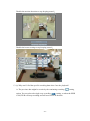
1
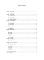
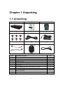
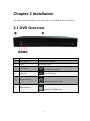
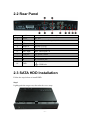
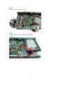
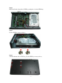
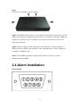
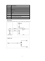
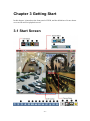
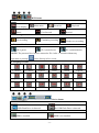
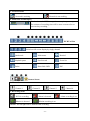
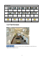
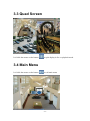
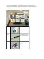
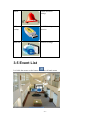
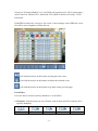
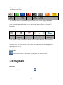
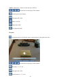
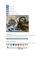
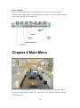
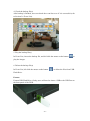
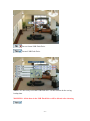
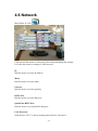
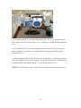
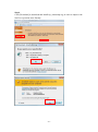
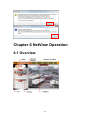
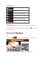
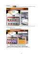
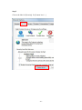
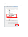
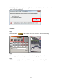
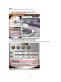
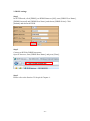
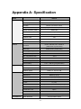
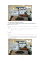
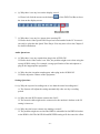
Killer HD4 User Guide Version 72040908 -1- Table of Contents Chapter 1 Unpacking ..................................................................................................... 3 1.1 Unpacking ........................................................................................................ 3 Chapter 2 Installation ..................................................................................................... 4 2.1 DVR Overview ................................................................................................ 4 2.2 Rear Panel ........................................................................................................ 5 2.3 SATA HDD Installation ................................................................................... 5 2.4 Alarm Installation............................................................................................. 8 Chapter 3 Getting Start ................................................................................................ 10 3.1 Start Screen .................................................................................................... 10 3.2 Full Screen ..................................................................................................... 13 3.3 Quad Screen ................................................................................................... 14 3.4 Main Menu ..................................................................................................... 14 3.5 Event List ....................................................................................................... 16 3.6 Playback ......................................................................................................... 18 Chapter 4 Main Menu .................................................................................................. 22 4.1 Camera ........................................................................................................... 23 4.2 Setup .............................................................................................................. 24 4.3 Record ............................................................................................................ 28 4.4 Alarm.............................................................................................................. 31 4.5 USB Backup................................................................................................... 33 4.6 Network.......................................................................................................... 38 Chapter 5 Network ....................................................................................................... 40 5.1 System Requirements..................................................................................... 40 5.2 Getting Start ................................................................................................... 40 Chapter 6 NetView Operation ...................................................................................... 44 6.1 Overview ........................................................................................................ 44 6.2 Live & Playback ............................................................................................ 45 6.3 Backup ........................................................................................................... 47 6.4 Setup .............................................................................................................. 53 6.5 PPPoE ............................................................................................................ 54 6.6 DDNS ............................................................................................................. 54 Appendix A: Specification ........................................................................................... 59 Appendix B: FAQ ........................................................................................................ 61 -2- Chapter 1 Unpacking 1.1 Unpacking Item 1 2 3 4 5 6 7 8 9 Name and description Pcs 1 DVR 1 2 User guide 1 3 Remote control 1 4 Screws (for HDD fixing) 6 5 Power cord 1 6 Power adaptor (AC 100~240V in, DC 12V out) 1 7 Cables of SATA HDD 2 8 Mouse (optional) 1 9 IR extension cord (optional) 1 NOTE: The type of mouse will be shipped at random. -3- Chapter 2 Installation This chapter includes DVR Overview, Rear Panel, SATA HDD & Alarm Installation. 2.1 DVR Overview Item Name Description 1 Front panel Indicators & USB port 2 Cover To protect HDD 3 IR receiver 4 USB port 5 Power indicator For IR remote control For USB backup Indicator of power status 6 HDD indicator Indicator of HDD status -4- 2.2 Rear Panel Item Name Description 1 Power DC 12V 2 D-SUB 9-pin For alarm device: Relay, NO, NC 3 VGA Video output 4 Audio in RCAx2 (1Vp-p) 5 Audio out RCA (L, R) (1Vp-p) 6 BNC input BNC video input x 4 7 USB port For mouse control 8 LAN RJ-45 9 IR IR extension jack 10 GND GND hole 2.3 SATA HDD Installation Follow the steps below to install HDD. Step 1 Lightly push the tongue out; then take the cover away. -5- Step 2 Plug the cables of HDD properly. Step 3 Plug the other end of the cables into the HDD. -6- Step 4 Mind and let the front side of HDD up, and place it in the HDD bay. Step 5 Fix the HDD by screws (silver). Step 6 Turn the bottom side of DVR up, fix the HDD by screws (silver). -7- Step 7 Fix the cover of DVR by screws (black). NOTE: The HDD will be started 5~30 seconds later after DVR is powered on. If the HDD is not detected, warning will be showed for 3 seconds by a message “HDD isn’t installed!” with beep every 10 seconds. User can turn off the buzzer or leave live mode to quiet down. NOTE: There are three reasons which may cause the above warning message: 1) HDD is broken 2) HDD is not installed 3) the recording mode is set as “single-way recording” and HDD is full. NOTE: If the HDD is not detected and started within 25 seconds, it will be determined a failed HDD. 2.4 Alarm Installation Pin Definition -8- Pin No Pin definition 1 Alarm-in 1 2 Alarm-in 2 3 Alarm-in 3 4 Alarm-in 4 5 COM 6 NC 7 NO 8 Do not connect to any cable. 9 GND Alarm figures Connect to NO (normal open) or NC (normal close) alarm device: -9- Chapter 3 Getting Start In this chapter, it introduces the front panel of DVR, and the definition of icons shown on event list and live/playback screen. 3.1 Start Screen - 10 - DVR Status 1. System Status Event list Main menu Live display Pause Playback Fast forward Rewind Continuing recording Single-way recording ID 1 (normal user) ID 2 (administrator) 2. Recording Mode No recording 3. Password level ID 0 (guest) NOTE: The password level will be returned to ID: 0 after 17 seconds without any operation or pressing twice directly in live screen. 4. Language of OSD T. Chinese S. Chinese Japanese Czech Dutch English Spanish French Italian German Polish Russian Hebrew Thai Danish Swedish Finnish Vietnamese Device Status 1. USB Flash Drive Status USB Flash Drive is detected 2. HDD Status No USB Flash Drive is detected HDD is installed HDD is not installed - 11 - 3. Network Status Network is not working Network is working 4. Status Bar of HDD Space This bar shows the HDD storage & consumption percentage. The estimate of recording time will be more accurate after at least one day recording. DVR Tool Bar DVR Tool Bar Switch to full screen display by singly channel Quad mode Main menu Rewind Playback/pause Fast forward Event list Delete Show/hide OSD ESC Camera Status 1. Channel Channel 1 Channel 2 Channel 3 Channel 4 2. Recording mode DVR is recording Alarm is detected Motion is detected Motion recording is on. NOTE: The red light will be flashed when recording. - 12 - Alarm recording is on 3. Frame Rate NTSC No recording 2fps 3fps 5fps 7.5fps 10fps 15fps No recording 1.6fps 2.5fps 4.1fps 6.2fps 8.3fps 12.5fps PAL 4. Image Quality Basic Normal Fine Good Excellent 3.2 Full Screen Left click the mouse on one of the buttons to switch full screen display in live or playback mode. - 13 - 3.3 Quad Screen Left click the mouse on the button to split display in live or playback mode. 3.4 Main Menu Left click the mouse on the button to call main menu - 14 - If users set “Password Enable” as O, the DVR will request at least level 1 (ID: 1) password to enter Main Menu. Default: ID: 1, Password: 1111 (Refer to Section 4.2 Setup – DVR Password) Camera Cameras settings Setup To set language, time or check DVR information Record Recording parameters settings - 15 - Alarm Alarm & motion settings USB backup For USB backup function Network Network settings 3.5 Event List Left click the mouse on the button to call main menu - 16 - If users set “Password Enable” as O, the DVR will request level 2 (ID: 2) password to enter Event List. Default: ID: 2, Password: 2222 (Refer to Section 4.2 Setup – DVR Password). Each HDD is allowed to save up to 256 events. If users change a new HDD, the event list will be moved together with the old one. Left click the mouse on this button to play/pause the event. Left click the mouse on this button to delete the selected event. Left click the mouse on this button to go back to the previous page. Event Filter Users are able to search events by channels, or event filters. 1. Channels: click the mouse on one of below icons to show specific events by all or specific channel(s). All Channels Channel 1 Channel 2 - 17 - Channel 3 Channel 4 2. Event Filters: click the mouse on one of below icons to show specific events by different event filters. All Filters Motion Video Loss Alarm HDD ON/OFF Power ON/OFF Mark The different colors of event filters enable users to search events simply. Meanwhile, each event filter is come with an auxiliary search cursor in same color, it is helpful to show users what happened when they are playing the images. (Refer to Section 3.7 Playback). Event Details Event No. Camera ON/OFF Filter Data/Time Event Source HDD/USB In the column of filter, it will show the filter icons in different colors, users can easily search the events. When the cursor is moved to one of the events, the background will be changed to the beginning of the event. Play Events Left click the mouse on this button to play/pause the selected event. 3.6 Playback Operation In live mode, left click the mouse on the button - 18 - to enter playback mode. USB If users set “Password Enable” as O, the DVR will request at least level 2 (ID: 2) password to playback mode. Default: ID: 2, Password: 2222 (Refer to Section 4.2 Setup – DVR Password) Left click the mouse on the numerals to select date, hour, minute, second or frame and then adjust them by “rolling up or down” the mouse. Left click the mouse on this bar to mark the import timing of video. - 19 - NOTE: Channel no. is shown on the left side of the bar. Switch full screen display of the channel. Switch quad screen display. Play/pause the video. Show event list. Show/hide OSD. Exit playback mode. Playback In playback mode, left click the mouse on this button to play/pause the video. Switch full screen display of the channel. Rewind x 1, 5, 15, 60 Play/pause the video. Fast forward x 1, 5, 15, 60 - 20 - Show event list. Show/hide OSD. Exit playback mode. Switch quad screen playback. Playback Mark Click the bar to mark the timing of important video when searching playback data, and the orange cursor will be shown in the center of the bar. Auxiliary Search Cursors: This smart search design allows users to search data quicker and easier, meanwhile, - 21 - For Example: Below pictures shows many events happened, users can click the numerals of date/time/frame and “roll up or down” the mouse to move one of the colorful cursors to the center red grid to view the event. Chapter 4 Main Menu If users set “Password Enable” as “O”, the DVR will request at least level 1 (ID: 1) password to main menu. Default: ID: 1, Password: 1111 (Refer to Section 4.2 Setup – DVR Password) - 22 - 4.1 Camera Main Manu Camera Left click the mouse on one of the cameras to enter the page of camera adjustment. Move and click the mouse to select brightness, contrast, hue or saturation, and roll up or down the mouse to adjust the image. - 23 - 4.2 Setup Main Menu Setup Move and click the mouse to select one of the items, or roll the mouse to adjust the settings. Load Default Load factory’s default configuration. Left click the mouse to select “No” or “Yes”. - 24 - Do not load factory’s default settings. Load factory’s default settings. NOTE: Load Default function will not change password, and the setting of “password enable/disable”. Language Click and roll the mouse on Language to choose OSD language. The DVR supports 18 versions of OSD language: T-Chinese, S-Chinese, Japanese, English, Czech, Dutch, Spanish, French, Italian, Deutsch, Polish, Russian, Hebrew, Thai, Danish, Swedish, Finnish and Vietnamese. NTSC/PAL Select Click and roll the mouse on NTSC/PAL Select to choose Auto, NTSC or PAL system. 1. Auto: The DVR will detect the camera’s system (NTSC or PAL) automatically when DVR is power on, if no camera installed, it will be the same as previous setting. 2. NTSC: The DVR will be set to NTSC even PAL cameras are installed. 3. PAL: The DVR will be set to PAL even NTSC cameras are installed. Date/Time Setup - 25 - Move and click the mouse to select one of the items, roll the mouse to adjust Date Mode, Date or Time. NOTE: It is necessary to click Exit/Update to save the settings. The date mode set here will be shown in the bottom-left corner of the screen. DVR Password Move and click the mouse to select one of the items, or roll the mouse to enable/disable password. 1. Password Enable: Only users of “ID: 2” are able to enable/disable password authority. Password Enable: the DVR will request password (ID: 1 or ID: 2) to enter Main Menu, users without password (ID: 0) are allowed live monitoring only. Password Disable: the DVR will NOT request password to enter Main Menu. - 26 - 2. User Password (ID: 1): users can change the password of ID: 1. (Default password: 1111) 3. Admin Password (ID: 2): users can change the password of ID: 2. (Default password: 2222) Click the numerals to set and confirm the value of password. NOTE: ID: 2 (Admin: user of level 2) is the administrator of DVR, who has the rights to manage passwords. ID 1 (Normal: level 1 users) is a normal user who can neither enable/disable password checking nor manage passwords. Information Users can check the DVR information including software, hardware, start/stop recording time of HDD and checksum. - 27 - 4.3 Record Main Menu Record Move and click the mouse to select one of the items, or roll the mouse to adjust the settings. Alarm/Motion Rate Set recording rate for the time when alarm or motion is triggered. Roll the mouse to adjust Alarm/Motion Rate. No recording when alarm or motion is detected. Working Hour Rate Set recording rate for normal working hours. Roll the mouse to adjust Working Hour Rate. No recording in working hours. Non-working Hour Rate Set recording rate for non-working hours. Roll the mouse to adjust Non-working Hour Rate. No recording in non-working hours. - 28 - NOTE: Working and non-working hours are programmable by setting schedule. NOTE: The event will still be recorded into the event list even Alarm/Motion Rate is set as Quality Star 1 stands for the most basic image quality for the longest recording time, whereas star 5 is for the best recording quality. NOTE: The background channel, image quality and frame rate will be changed immediately when users adjust the settings. Audio Users can install audio devices in channel 1 and channel 2. Roll the mouse to enable/disable Audio function. Enable audio function: Audio works both in live & playback. Disabled audio function: Audio doesn’t work neither in live nor playback. Record Mode Roll the mouse to adjust the Record Mode.. No Recording: the DVR will NOT record. Continuing Recording: the HDD will be overwritten when it is full. HDD status bar will show “100%”, but it will continue recording. Single-way Recording: the DVR will stop recording when the HDD is full until the recording mode is changed to or format the HDD. - 29 - NOTE: If users use more than two HDDs in turn, it is suggested to set the record mode as “single-way recording” to prevent overwriting. Schedule Recording schedule is programmable for working & non-working hours. Move and left click the mouse to move the cursor, roll the mouse to enlarge or narrow the cursor. Left click the mouse twice to switch the zone from Working or Non-working Hours. Working Hours Non-working Hours NOTE: The function of Alarm/Motion will not be conflicted by schedule. Format HDD - 30 - Cancel HDD format. Format HDD. NOTE: When a new HDD is installed, it will show a message “Unformatted HDD!” on the screen, users can format HDD via this function, and set record mode. If an old HDD is installed instead, the DVR will remain the original record mode of the HDD, but users can change it as well. NOTE: The estimate of recording time will be more accurate after at least one day recording. WARNING: All the recorded data including event list will be deleted after format HDD. 4.4 Alarm Main Menu Alarm Click and roll the mouse to select one of the items and change the settings. Left click the mouse to enter Motion settings. - 31 - Video Loss Alarm Roll the mouse to enable video loss alarm Roll the mouse to disable video loss alarm Response Duration Roll the mouse to adjust response duration. Users can set post-recording time in this item. When alarm/motion is happened, the post-recording time will be lasted for 1-255 seconds with an alarm or motion message and beep sound. If a new alarm/motion is happened in the meanwhile, the post-recording function will be on again for 1-255 seconds. Users can turn off the buzzer, but the notification will still be showed on the screen. Alarm Full Screen Roll the mouse to enable alarm full screen. Roll the mouse to disable alarm full screen. Buzzer Roll the mouse to turn on the buzzer. Roll the mouse to turn off the buzzer. Motion - 32 - Left click the mouse the select one of the cameras. Move and left click the mouse to set motion detection zones. Roll the mouse to adjust the sensitivity of motion zones. The bigger the number, the higher the sensitivity. 4.5 USB Backup Main Menu USB Backup Click and roll the mouse to select one of the items and change the settings. Left click the mouse to Save or Format USB Flash Drive - 33 - NOTE: Users will need to format the USB Flash Drive before using it for backup video or upgrade OS. Start Time Roll the mouse to set the start time of data which is going to be saved to USB Flash Drive. Stop Time Roll the mouse to set the stop time of data which is going to be saved to USB Flash Drive. NOTE: If there is data between the start and stop time, a data bar will be shown on the bottom of screen. NOTE: One USB Flash Drive can be saved maximum 16 files, up to 1 GB or 30 minutes per file. Channel Roll the mouse to choose a channel which is going to be backup. Save 1. Check USB Flash Drive When a USB Flash Drive is inserted into the DVR, it will show “USB Check OK!” on the screen. Format USB Flash Drive if the message shown. - 34 - 2. USB Flash Drive Storage Requirement The DVR supports 128MB~8GB capacity of USB Flash Drive. 3. Backup Backup the data into USB Flash Drive, the file will be named by Start Time as “C_YYYYMMDDhhmmss.mov” (see below table) with “FAT 16” form which can be played by Quick Time Player. File Name Definition C Channel No. (ex.ch01) YYYY Year (ex.2008) MM Month (ex.01) DD Date (ex.11) hh Hour (ex.13) mm Minute(ex. 22) ss Second (ex. 33) For Example:ch01_20080111132233.mov - 35 - 4. Check the backup file(s) After backup is finished, users can check the event list to see if it is successful (refer to Section 3.6 Event List). 5. Play the backup file(s) In Event List, choose the backup file, and left click the mouse on the button to play the images. 6. Delete the backup file(s) In Event List, left click the mouse on the button to delete the files from USB Flash Drive. Format Format USB Flash Drive, firstly, users will need to insert a USB to the USB Port on the front panel of the DVR. - 36 - Do not format USB Flash Drive. Format USB Flash Drive. NOTE: It is necessary to format USB flash drive via this function before saving backup data. WARNING: All the data in the USB Flash Drive will be deleted after choosing - 37 - 4.6 Network Main Menu LAN Click and roll the mouse to select one of the items and change the settings. Left click the mouse to manager LAN Password. IP Roll the mouse to set the IP address Mask Roll the mouse to set the mask Gateway Roll the mouse to set the gateway HTTP Port Roll the mouse to set the http port QuickTime HTTP Port Roll the mouse to set QuicktTme http port LAN Password Only the user “ID 2” is able to manage passwords for LAN users. - 38 - 1. Guest Password (ID: 7): click the numerals in the circle to set Guest Password. This is the lowest level, only remote “Live” viewing is available (default password: 1111) 2. User Password (ID: 8): click the numerals in the circle to set User Password. This is normal level, remote “Live & Playback” viewing are available (default password: 2222) 3. Admin Password (ID: 9): click the numerals in the circle to set Admin Password. This is the highest level, not only remote viewing, admin can also set IE parameters including PPPoE and DDNS settings…etc. (default password: 3333) NOTE: The DVR only provide 1 user to access images remotely at the same time. - 39 - Chapter 5 Network 5.1 System Requirements It is necessary to prepare for a PC which is come with qualified versions of hardware and software to make IE connect System Requirements 1. PC: Intel Pentium III or higher, 512MB RAM, 1GB HDD space 2. Operating System: Microsoft Windows 2000, XP or Vista 3. Web Browser: Internet Explorer 6.0 or above 4. Quick Time: please surf www.apple.com/quicktime/download to download a version 7.0 or above. 5.2 Getting Start Before connecting to DVR via IE browser, users will need to change some settings of QuickTime Player and NetView as below steps. Step 1 Open QuickTime Player, choose [Edit] [Preferences] [QuickTime Preferences] - 40 - Step 2 Choose [Advanced] → set Transport Setup as [Custom…] Set Transportation Protocol as [HTTP] → and set Port ID as [80] → [OK] NOTE: The default Port ID is 80, users are able to change the value properly according to their network settings. Step 3 Open IE browser, enter IP address of the DVR, and press [Enter]. (The default IP address of the DVR: 192.168.0.89) - 41 - Step 4 Enter ID and Password to login to the NetView The default passwords of users. Guest Password User Password Admin Password ID 7 8 9 Password 1111 2222 3333 Step 5 Click the button of [SETUP] - 42 - Step 6 Click [Download] to download and install tcp_timestamp.reg, in order to improve the NetView operation more fluently. - 43 - Chapter 6 NetView Operation 6.1 Overview - 44 - Channel Status Users are able to monitor Live video of the channel is working good. Video loss in the channel. An alarm is triggered in the channel. Video loss but an alarm is triggered in the channel. Motion is detected in the cahnnel.. An alarm and motion are both triggered in the channel. Message Window In live mode, it will show current time, in playback mode, playback time will be shown instead. If it shows [Disconnection], please click the button or press [F5] to refresh the web page. 6.2 Live & Playback Live Click the button and choose one of the channels for remote live viewing. NOTE: All users ID: 7, 8 and 9 are able to monitor live images remotely. - 45 - Playback Click the button and choose one of the channels for playback viewing. Search an appropriate date & time, and click rewind, pause/play or fast forward to view the playback video. NOTE: Only users of ID: 8 and 9 are able to enter playback model. - 46 - 6.3 Backup 1. Initial settings of backup function Before operating backup function, users will need to download unsigned ActiveX controls as following steps: Step 1 Click [Tool] of IE browser, choose [Internet Options] - 47 - Step 2 Choose the label of [Security] [Custom level…] - 48 - Step 3 Find the item [Download unsigned ActiveX controls] choose [Prompt] [OK] - 49 - Step 4 Click the button [BACKUP] There will be an information bar and windows message showing [Did you notice the Information Bar?] Click [Close] Information Bar Step 5 Right-click the information bar, choose [Install ActiveX Control…] - 50 - Click [OK] while a message is shown [Windows has blocked this software because it can’t verify the publisher.] 2. Backup Step 1 Click the button function. and choose one of the channels for remote backup Step 2 Select an appropriate start/stop date & time which is going to be saved. Step 3 Click the button […] to select a path of the computer to save the backup file. - 51 - Step 4 Press the button [Start] to start downloading the file. Users can press the button [Stop] to stop downloading while the file is transferring. NOTE: Only users of ID: 9 are able to enter backup model. - 52 - 6.4 Setup Click the button [Setup] to set the network settings. NOTE: All Users of ID: 7, 8 and 9 are able to enter setup mode, but only ID: 9 is authorized to change DDNS and PPPoE settings. 1. Streaming Click [Streaming] to set the ports for Http and QuickTime, click [Submit] to save the settings. 2. Bitrate Click [Bitrate] to select an appropriate bitrate → click [Send] to save the setting. NOTE: The higher the Bitrate, the better the video quality, and lower the frame rate. Intranet users should choose “Intranet” for the best video quality. - 53 - 6.5 PPPoE PPPoE, Point-to-Point Protocol over Ethernet, is a network protocol used mainly with ADSL services. PPPoE Settings In Setup mode, click [PPPoE]. Set PPPoE Status as [ON], and enter the [PPPoE User Name] and [PPPoE Password] assigned by the ADSL service provider. Click [Submit] and reboot the DVR. 6.6 DDNS DDNS, Dynamic DNS allows the domain name data held in a name server to be updated in real time. The most common use for this is in allowing an Internet domain name to be assigned to a computer with a dynamic IP address. The following is an example to create a DDNS account for users’ reference. - 54 - 1. Create a free DDNS account and host name from DynDNS Step 1 Go to the website www.dyndns.com and click [Create Account]. Create Account Step 2 Enter the [User Information]: [Username], [Email Address] and [Password] to create a DDNS account. Please be minded that it is necessary to put on an effective IP address, and remember the password, as it will be confirmed and noticed by email. Check the two boxes below the [Terms of Service] - 55 - Click the button [Create Account] on the bottom of the page. The account is created, and users should receive the confirmation email within a few minutes. Step 3 Check the email box, and find the confirmation email sent by DynDNS Support. Visit the confirmation address to complete the account creation process. The account is confirmed, click [login] to start using the account. Login - 56 - Enter the [Username] and [Password] click the button [Login] Click the item [Add Host Services] Add Host Services Step 4 Create new hostname, enter [Hostname], [Service Type] and [IP Address] click [Create Host] - 57 - 2. DDNS settings Step 1 In SETUP mode, click [DDNS], set DDNS Status as [ON], enter [DDNS User Name], [DDNS Password] and [DDNS Host Name], and choose [DDNS Select]. Click [Submit] and reboot the DVR. Step 2 Connect to DVR by DDNS host name. Open IE browser, enter [DDNS Host Name], and press [Enter]. Step 3 Please refer to the Section 5.2 Step 4 & Chapter 6.. - 58 - Appendix A: Specification Model Function UM7204 No. of cameras 4 Split display mode 1, 4 Operation Multiplex mode Mouse / IR remote control Quadruplex (Live/Record/Playback/Ethernet) Display resolution (VGA) 1280x1024 Live frame rate 120fps (NTSC), 100fps (PAL) Color Record 16M colors (Y:8, U:8, V:8) 4:2:2 Playback mark Yes Watch dog Yes Wall mount Yes NTSC: 640x480, PAL: 640x512 Resolution (1280x1024 at quad mode) Frame rate 60fps (NTSC), 50fps (PAL) Recording quality Playback Connector 5 levels Compression algorithm H.264 enhanced Max. compression rate 300:1 Motion recording Yes Pre-recording 3 sec ~ 10 sec Post-recording 1 sec ~ 255 sec (programmable) Search mode Smart search by file/event/frame/time/date Search speed Date, hour, min, sec, frame, pause Playback speed Pause, x1, x5, x15, x60 Video out VGA x1 Audio line in RCAx2 (1 Vp-p) Audio line out RCA (L,R) (1 Vp-p) Ethernet 10/100M RJ45x1 DC jack x1 (12V) DSUB9 1 (Alarm-in x4, Alarm-out x1),relay IR extension jack x1 IR extension cord option IR receiver Yes USB port Alarm/Motion x2 (Mouse x 1/ USB flash x 1) Motion detection 12 (4x3) motion zones - 59 - Motion detection sensitivity No. of alarm inputs 4 No. of alarm outputs 1 Alarm type Event Ethernet 100 levels Relay, NO (Normal Open), NC (Normal Close) Size of event list 256 events Event source Alarm, motion, video loss, power loss 10/100M LAN Yes Remote viewing Backup IE, suggested resolution: 1024x768 PPPoE Yes DDNS Yes HDD capacity SATA 3.5", 120GB ~ 500GB USB Specification Yes Remote backup Yes, via IE browser Adapter output DC12V Voltage range 100~240V Power consumption Max. 30W Operating temperature 5 ~ 40 ℃ Operating relative humidity 10 ~ 75 % Net weight 1.15 ± 0.1 kg Shipping weight 1.9 ± 0.1 kg Dimension (mm) 290x180x41.8 (W x L x H) - 60 - Appendix B: FAQ HDD Questions: 1. Q: Why does the DVR not recording after the HDD is installed? A: The problem might occur when the HDD is not well installed or unformatted; or the DVR power is being turn off or the Recording Rate setting is Zero or the Record Mode setting is selected (the single-way recording selection will stop recording when the DVR is full). 2. Q: How do I turn off the message “HDD is not installed” on the display screen? A: Please install the HDD or you may switch off the beeping sound by turn off the BUZZER under the ALARM setting. - 61 - 3. Q: Can I take the HDD to play at the PC? A: NO! The format setting is different and it cannot be recognized thru PC. USB Flash Drive Questions: 4. Q: Why can’t I play the “.mov” file when I backup the data in the USB Flash Drive? A: The problem might occur when using the unsuitable display software. Please use the Quick Time Player to display the “.mov” file. Display Questions: 5. Q: Why the monitor screen is showing the twisted images and the color is not right? A: The problem might occur when there are two different NTSC/PAL system accessories being used. Please check the SET UP setting and then select the appropriated system. - 62 - 6. Q: Why there is no any icon on the display screen? A: Please left click the mouse on the button of the DVR Tool Bar to show the icon on the display screen. 7. Q: Why there is no any live image when entering IE? A: Please check if the Quick Time Player has been installed in the PC because it can only be play thru the Quick Time Player. You may also refer to the Chapter 5 for detail information. Audio Questions: 8. Q: Why there is no any sound when plug in the AUDIO IN? A: Please check if the Audio is on. Also, the problem might occur when using the wrong AUDIO setting. For example, wrong specification of the microphone or plug in the inappropriate equipment. 9. Q: Why does the irregular sound appear when plug in the AUDIO IN? A: Please adjust the volume of the equipment. Setting Questions: 10. Q: Why the expected recording time is less than the actual recording time? A: The System will adjust the setting automatically after one day recording period. 11. Q: Why does the DVR cannot connect thru LAN? A: The network cable might not be connected or the modem is broken or the IP setting is incorrect. 12. Q: Why does the buzzer cannot stop making a sound? A: The problem might occur when the HDD is uninstalled or the HDD is broken or the HDD is full. The MOTION and BUZZER setting will also cause the effect. - 63 - Disable the motion detection to stop beeping sound. ↓ Disable the buzzer setting to stop beeping sound. ↓ 13. Q: Why can’t I find the specific recording data when I use the playback? A: The previous data might be rewrite by the continuing recording setting option. You can select the single-way recording setting, so when the HDD is full, DVR will stop recording and will not rewrite on the data. - 64 - Others: 14. Q: What if I forgot the password? A: Please contact your supplier. 15. Q: Why the DVR is being interfered by other remote control? A: There is no problem of interference or cross talk if a single remote control is used. Even if a plurality of remote controls is used, there is no problem of interference or cross talk as long as each remote control is used at a different time. 16. Q: How to set up for DDNS account and all the related settings? A: Please refer to the Chapter 5 for detail instruction. - 65 -