1
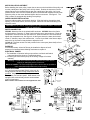
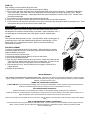
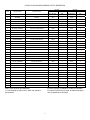
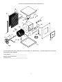
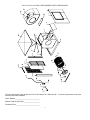
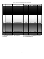
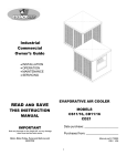
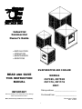
Industrial
Commercial
Owner’s Guide
• INSTALLATION
• OPERATION
• MAINTENANCE
• SERVICING
EVAPORATIVE AIR COOLER
READ AND SAVE
MODELS
CS75/85, CD75/85
CS11/16, CD11/16
CD21
THIS INSTRUCTION
MANUAL
IMPORTANT
Date purchase: _____________________
Note any damage on the freight bill, as any damage
claim must be filed with carrier.
Purchased from: ____________________
Motor, Motor Pulley and Belt are sold separately
Manual part # 70888
REV. 2/19/02
1
INSTALLATION OF EVAPORATIVE COOLERS
PREPARATION
1. All electrical and duct work must comply with local and federal codes.
2. Make arrangements to get the cooler from ground to roof (crane, hoist, etc.).
LOCATION
1. Cooler should not be mounted near exhaust openings or vent pipes where fumes and odors can be drawn into cooler.
2. Ensure mounting surface is strong enough to support the cooler. Operating weight will be much heavier than shipping
weight.
3. Locate cooler so that fresh air is drawn in; air is not recirculated.
ROOF MOUNT UNITS
1. Select the location, taking into account roof construction and duct requirements. If rafters are cut when the roof
opening is cut, be sure to strengthen them.
2. Purchase or construct a platform to provide a level, mounting surface for the cooler. Always mount the cooler high
enough to allow easy access to the drain fitting.
3. Measure cooler or use the spec sheet to determine size of platform. Platform must be located so that the discharge
opening of the cooler is in line with the ductwork. On pitched roofs, the platform frame may be covered with
galvanized sheet steel or other weatherproof materials. An opening or removable panel must be left to allow access
to the drain fitting. On down discharge coolers the duct should be fastened to the platform collar before cooler is set
in place. The duct should have a standing flange for the cooler discharge opening to fit. Flash and seal the duct and
roof opening to provide weather tightness.
CAUTION: TO AVOID RISK OF FIRE, ELECTRICAL SHOCK, OR SERIOUS PERSONAL INJURY, BE SURE TO
DISCONNECT POWER FROM UNIT BEFORE CLEANING OR SERVICING.
WARNING: TO REDUCE THE RISK OF FIRE OR SHOCK; DO NOT USE THIS FAN WITH ANY SOLID STATE SPEED
CONTROL DEVICE.
DUCT WORK
1. The most important rule to follow when designing duct work is: AN EVAPORATIVE COOLER DEPENDS UPON A
LARGE VOLUME OF AIR COMING OUT OF THE DUCT WORK AT HIGH VELOCITY IN ORDER TO COOL
PROPERLY.
2. Do not “reduce” the discharge opening of the cooler.
3. Do not undersize the duct work and make it much smaller than the discharge opening. (In most cases, air conditioning
duct work is too small for coolers.)
4. Extra long ducts cause static pressure and will reduce airflow. They also pick up heat and diminish the effect of the
cooled air.
5. The motor pulley may be adjusted to compensate for ductwork.
6. Sharp or abrupt bends hinder airflow.
7. Poorly designed ceiling diffusers will ruin a successful installation. Install diffusers that are designed for use with
evaporative coolers.
MOTOR INSTALLATION
After cooler is in place and level, remove the motor from the box
and inspect for shipping damage. Ensure that the motor voltage,
phase and horsepower are correct. Mount motor on motor mount
as shown.
CS75/85, CD75/85
Secure motor to mount using the mounting straps provided. When
using motors with a 143T or 145T frame, remove the yolks from the
motor mount and bolt the motor to the motor mount using the slots
provided.
CS11/16, CD11/16 & CD21
Mount the motor using the slots that align the motor pulley and blower pulley.
BELT ADJUSTMENT
An improperly adjusted belt will greatly shorten motor life. A deflection of ¾” with finger
force will indicate proper adjustment. (Figure 1)
Do not use the motor pulley to adjust belt tension.
Always use the motor mount to adjust the belt. (Figure 1)
2
MOTOR PULLEY ADJUSTMENT
Before installing the motor pulley, loosen the set screw on the back side of the pulley and
turn the outside jaw of the pulley until it is fully closed. Position the set screw over the
closest flat spot in the thread and then open the outside jaw of the pulley 4 or 5 turns.
Position the set screw over the closest flat spot in the thread and retighten the set screw.
Place the pulley on the motor shaft and tighten the front set screw. See figure 2. The
CD21 coolers are equipped with double groove pulleys.
OVERFLOW PIPE INSTALLATION
Place the rubber washer onto the drain bushing. Slide the bushing through the drain
opening, in the cooler bottom, from the top side. Screw the nut onto the bushing from
under the cooler.
CAUTION: DO NOT HOOK THIS COOLER TO A WATER SOFTENER. THIS WILL
VOID THE WARRANTY.
WATER CONNECTION
CD75/85: Mount the float in the splash baffle as shown. CS75/85: Mount the float in
the float bracket. Route the ¼” water line through the corner post as shown. Place the
compression nut and ferrule onto the water line. Slide the water line into the float and
tighten the compression nut. See figure 4. As the figure shows, the water level should
remain ½” below the top of the overflow tube. A screw is provided in the float to adjust
water level; or the float rod may be bent to adjust the level.
11/16 & 21: The float mounts in a hole provided in the corner post (down draft) or front
panel (side draft).
BLEEDOFF
In hard water areas, a bleed off kit may be installed to dispose of small
amounts of mineralized water allowing fresh water to replace it.
ELECTRICAL POWER
1. The installation of electrical wiring must conform to all local and federal
codes and should be done by a certified electrician.
2. Connecting the motor and/or pump to the wrong voltage will void the
warranty.
Warning: To avoid risk of electrical shock, disconnect the power before
opening or attempting service on this unit.
Notice to Installer: The motor amperage must be set as close as possible to
motor nameplate amps without the pump running.
WIRING DIAGRAMS
A 4” j box has been provided (75/85), in the unit, for
1
3
wiring purposes. No other wiring components will be
provided. Single phase: one and two speed.
PUMP
Three phase; one and two speed. Motor starter to be
equipped with overload relay sized to accommodate
motor full load amps.
Reservoir
BLACK
STRIPED
RED
MOTOR
BROWN
SINGLE SPEED
DIAGRAM
3
115V SUPPLY
Motor starters and overloads are not supplied with units.
PUMP
RED
GREEN
3
START UP
After installing cooler and before filling with water:
1. Open windows and doors or other exhaust openings in building.
2. Turn on cooler and check amperage at the incoming white lead, using clamp on ammeter. If amperage reads above
motor name plate, refer to the motor pulley adjustment instructions (page 2) and open the pulley ½ turn. Restart
cooler and recheck amperage. If amperage reads below motor name plate, close the pulley ½ turn. Restart cooler
and recheck amperage.
3. Turn on water to cooler and ensure that connections do not leak.
4. Fill pan to ½” below top of overflow tube and ensure that the float cuts off water completely.
5. Turn the switch to cool and check that water is coming from the water trays and that the pads are wetting evenly. There
are screws at the top of the louvers to level the water trays.
MAINTENANCE
CAUTION: Turn off all electrical power to this unit before opening or attempting any service.
Occasionally inspect your cooler for leaks, loose belt, blocked water lines, correct
belt alignment or excessive residue buildup on the pads. Inspect cabinet for rust. If
rust spots appear, sand and paint with a high-grade, corrosion resistant paint.
OILING
Lube the blower bearings twice per year. Use SAE 20W or 30W, non-detergent oil
on bearings with oil cups and standard bearing grease on ball bearings. Oil the
blower motor if it is equipped with oil holes. Some motors are permanently
lubricated at the factory.
PAD REPLACEMENT
It is best to change pads at the end of the season. When old pads (covered by
minerals and salts) are left in the cooler during the wet winter months, there is a
greater possibility for corrosion.
1. Remove the louver from the cooler.
2. Unhook pad retainers from the sides of the louver and remove.
3. Remove the old pad and discard.
4. Clean any dirt or sediment that has built up on louver. Inspect the water tray and
clean any dirt or sediment that has built up in the water slots. If louver has rust
spots, sand and paint with a high-grade, corrosion resistant paint.
5. Tuck new pad into louver, ensuring that there are no gaps to allow hot air to
bypass the pad
6. Replace the pad retainers.
LIMITED WARRANTY
This warranty is extended to the original purchaser only. It does not cover damages incurred during shipping or through accident,
neglect, or abuse by the owner. Essick Air Products does not authorize any person or representative to assume any other or different
liability in connection with this cooler.
TERMS AND CONDITIONS OF WARRANTY
The BOTTOM PAN is guaranteed against leakage due to rusting out for Five Years. All other original parts provided by Essick Air
Products are warranted against defects in material or factory workmanship for One Year.
EXCLUSIONS FROM THE WARANTY
Essick Air Products is not responsible for incidental or consequential damage resulting from any malfunction.
Essick Air Products is not responsible for any damage occurring from the use of water softeners, chemicals, descale material, or if a
higher horsepower motor than what Essick Air Products recommends is used in the unit.
Essick Air Products is not responsible for the cost of service calls to diagnose cause of trouble, or labor charge to repair and/or replace
parts.
HOW TO OBTAIN SERVICE UNDER THIS WARRANTY
Contact the Dealer where you purchased the evaporative cooler. If for any reason you are not satisfied with the response from the
dealer, contact Customer Service Department: Essick Air Products Inc. 5800 Murray Street, Little Rock, Arkansas 72209.
Phone 1-800-643-8341
4
CS75/85 & CD75/85 REPLACEMENT PARTS / REPUESTOS
ITEM
CS75/85
PART NO.
NO. DE REF.
CD75/85
PART NO.
NO. DE REF.
DESCRIPTION
DESCRIPCIÓN
1
TOP
SUPERE
70410
1
70380
1
2
BOTTOM
FONDO
70411
1
70398
1
3
FRONT
FRENTE
70414
1
***
***
QTY.
CAN.
QTY.
CAN.
4
LEFT CORNER POST
POST ESQUINERO LEFT
70475
1
***
***
4
RIGHT CORNER POST
POST ESQUINERO RIGHT
70384
1
***
***
4
CORNER POST
POSTE ESQUINERO
***
***
70481
4
5
BLOWER HOUSING
CAJA DEL VENTILADOR
70402
1
70402
1
6
CUTOFF
TAPA DE LA CAJA DEL VENTILADOR
70395
1
70395
1
7
MOTOR MOUNT
MONTAJE DEL MOTOR
70408
1
70408
1
8
BEARING ANGLE
ANGULO PARA CHUMACERA
70393
2
70393
2
9
SPLASH BAFFLE
DEFLECTOR
***
***
70444
2
10
BLOWER WHEEL
EL SOPLADOR RUELA
70403
1
70403
1
11
BLOWER SHAFT
EJE DEL VENTILADOR
70438
1
70438
1
12
KEY
PASADOR
589041
2
589041
2
13
SET COLLAR
COLLAR FIJO
501243
2
501243
2
14
BEARING
CONJINETE
583004
2
583004
2
15
PULLEY
POLEA DEL VENTILADOR
583035
1
583035
1
16
LOUVER
LA REJILLA
70385
3
70385
4
17
WATER TRAY
LA AGUA EL BANDEJA
70397
3
70397
4
18
FILTER SET
FIJO DE FILTRE
70485
1
70486
1
19
PAD RETAINER
RELLENE RETENEDOR
70396
15
70396
20
*
LOUVER ASSEMBLY
JUEGO DE REJILLA
70399
3
70399
4
20
WATER DISTRIBUTOR
DISTRIBUIDOR DE AGUA
70405
1
70404
1
21
WATER TUBE HOLDER
EL TENEDOR DE CAÑO DE AGUA
524304
6
524304
8
22
FLOAT BRACKET
ABRAZADERA DEL FLOTADOR
70413
1
***
***
23
FLOAT VALVE
VÁLVULA FLOTADORA
524198
1
524198
1
24
PUMP
BOMBA
506605
1
506605
1
25
PUMP BRACKET
ABRAZADERA DE LA BOMBA
70488
1
70488
1
26
WATER HOSE
MANGUERA DEL AGUA
598400
60”
598400
60”
27
OVERFLOW KIT
EQUIPO DE DESBORDIMENTO
515100
1
515100
1
28
DUCT FLANGE
LA BRIDA
70419
1
***
***
29
BOTTOM DUCT FLANGE
LA BRIDA BOTTOM
70576
2
***
***
30
BLOWER BRACE
ABRAZADERA DEL VENTILADOR
70483
2
70394
4
Motor, pulley and belt sold separately.
*Louver assembly includes louver, water tray, pad and
pad retainers.
El motor, la polea y la banda se venden por separado.
El juego de rejilla incluye la rejilla, la charola para agua,
filtro y sujetadores de los filtros.
5
CS75/85 & CD75/85 REPLACEMENT PARTS / REPUESTOS
To order replacement parts, please call “The Cooler Hotline” at 1-800-643-8341. To ensure prompt service, have the
following information available.
Cooler Model #_____________________________
Manual # and Revision Date___________________
Purchased From_____________________________
6
CS11/16, CD11/16 & CD21 REPLACEMENT PARTS / REACCIONES
To order replacement parts, please call “The Cooler Hotline” at 1-800-643-8341. To ensure prompt service, have the
following information available.
Cooler Model #______________________________
Manual # and Revision Date____________________
Purchased From_____________________________
7
CS11/16, CD11/16 & CD21 REPLACEMENT PARTS / REACCIONES
CS11/16
CD11/16 & CD21
DESCRIPTION
DESCRIPCIÓN
PART NO.
NO. DE REF.
1
FRONT
FRENTE
70697
2
BOTTOM
FONDO
70702
3
BLOWER HOUSING
CAJA DEL VENTILADOR
70703
1
4
CUTOFF
TAPA DE LA CAJA DEL VENTILADOR
70705
5
TOP
SUPERE
500220
6
MOTOR MOUNT
MONTAJE DEL MOTOR
7
WATER DISTRIBUTOR
8
BLOWER BRACE
9
CENTER POST
10
PAD RETAINER
ITEM
QTY.
CAN.
PART NO.
NO. DE REF.
QTY.
CAN.
1
***
***
1
70681
1
***
***
1
70694
1
1
500220
1
70687
1
70687
1
DISTRIBUIDOR DE AGUA
500713
1
500712
1
ABRAZADERA DEL VENTILADOR
500852
2
500852
2
POSTE CENTRO
501466
3
501466
4
RELLENE RETENEDOR
500603
6
500603
8
11
FILTER
FILTRE
524093
6
524093
8
12
LOUVER
LA REJILLA
501352
6
501352
8
13
WATER TRAY
LA AGUA EL BANDEJA
500677
6
500677
8
*
LOUVER ASSEMBLY
JUEGO DE REJILLA
503396
6
503396
8
14
CORNER POST
POST ESQUINERO
500098
1
500098
2
15
WATER HOSE
MANGUERA DEL AGUA
598400
60”
598400
60”
16
PUMP BRACKET
ABRAZADERA DE LA BOMBA
70488
1
70488
1
17
OVERFLOW KIT
EQUIPO DE DESBORDIMENTO
515100
1
515100
1
18
FLOAT VALVE
VÁLVULA FLOTADORA
524198
1
524198
1
19
SET COLLAR
COLLAR FIJO
501242
2
501242
2
20
BLOWER WHEEL
EL SOPLADOR RUELA
70640
1
70640
1
21
BLOWER SHAFT
EJE DEL VENTILADOR
70672
1
70672
1
2
22
KEY
PASADOR
589041
2
589041
23
PULLEY
POLEA DEL VENTILADOR
583095
1
583095
1
24
BEARING
CONJINETE
583005
2
583005
2
25
BEARING ANGLE
ANGULO PARA CHUMACERA
514498
2
514498
2
26
BLOWER HOUSING
CAJA DEL VENTILADOR
***
***
70688
1
27
MOTOR MOUNT (CD21)
MONTAJE DEL MOTOR (CD21)
***
***
512491
1
28
SPLASH BAFFLE
DEFLECTOR
***
***
501464
2
29
PUMP
BOMBA
1
Motor, pulley and belt sold separatelY.
*Louver assembly includes louver, water tray, pad and
pad retainers.
1
El motor, la polea y la banda se venden por separado.
El juego de rejilla incluye la rejilla, la charola para agua,
filtro y sujetadores de los filtros.
8