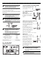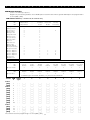
1
System Introduction
S
1.1
E
C
T
I
Specifications
O
N
1
Digital Communicator Specifications
• Supports major communication formats including SIA and
Contact ID
• Event-initiated personal paging
• Three programmable telephone numbers
• Two account numbers
• Supports LINKS1000 cellular communication
• Supports LINKS2X50 Long Range Radio Transmitter
• DTMF and pulse dialing
• DPDT line seizure
• Anti-jam feature
• Split reporting of selected transmissions to each telephone
number
Downloading Software Support
• PC5008 uses DLS-1 v6.5 and up.
Flexible Zone Configuration
• Six fully programmable zones; system expandable to eight
zones using keypad zone inputs and wireless zones
• 38 access codes: one master code, one maintenance code,
two duress codes, two supervision codes and 32 general
access codes
• 27 zone types; 8 programmable zone attributes
• Normally closed, single EOL and double EOL zone wiring
• Eight wireless zones available using the PC5132 Wireless
Receiver
System Supervision Features
The PC5008 continuously monitors a number of possible trouble
conditions including:
• AC power failure
• Trouble by zone
• Tamper by zone
• Fire trouble
• Telephone line trouble
• Failure to communicate
• Low battery condition
• Bell output trouble
• Module fault (supervisory or tamper)
• Loss of internal clock
• AUX Power Supply Trouble
Audible Alarm Output
• 700mA Supervised Bell Output (current limited at 3 amps),
12VDC
• Steady or Pulsed Output
EEPROM Memory
• Does not lose programming or system status on complete AC
and Battery failure
Programmable Outputs
• One programmable voltage output and one programmable
voltage output/input; 22 programmable options
• PGM1 = 300mA; PGM2 = 50mA
• Eight additional low current (50mA) outputs available using
the PC5208 module
• Four additional high current (300mA) outputs available using
the PC5204 module; one PC5204 output fully supervised for
siren
False Alarm Prevention Features
• Audible Exit Delay
• Audible Exit Fault
• Communication Delay
• Urgency on Entry Delay
• Quick Exit
• Cross Zone Burglary Alarm
• Rotating Keypress Buffer
Powerful 1.5 Amp Regulated Power Supply
• 550 mA Auxiliary Supply, 12 VDC
• Positive Temperature Coefficient (PTC) components replace
fuses
• Supervision for loss of AC power, low battery
• Internal clock locked to AC power frequency
Additional Features
• Auto Arm at specified time
• Keypad-activated alarm output and communicator test
• All modules connect to the system via a four wire Keybus up
to 1000’/330m from main panel
• An event buffer which records the past 128 events with both
the time and date at which they occurred; buffer can be
printed using PC5400 serial interface module, or viewed with
the LCD5500Z keypad.
• Supports the addition of the PC5132 Wireless receiver for
integration of wireless devices
• Uploading and downloading capability
• Local downloading capability through the use of the PC-LINK
adaptor
• Supports the Escort5580 Voice Prompt Module with
Automation/Lighting Control
• Supports the addition of the PC5928 Audio Interface Module
to integrate intercom stations
• Added Keybus fault protection: clock and data outputs have
been programmed to withstand shorts to +12v to prevent
control panel damage
Power Requirements
• Transformer = 16.5 VAC, 40VA
• Battery = 12 volt 4 Ah minimum rechargeable sealed lead
acid battery
Remote Keypad Specifications
• Two keypads available:
- PC5508Z eight zone LED keypad with zone input
- LCD5500Z Alphanumeric keypad with zone input
• All keypads have five programmable function keys
• Connect up to eight keypads
• 4-wire (Quad) connection to Keybus
• Built in piezoelectric buzzer
1
S
1.2
Y
S
T
E
M
V
I
N
T
O
D
U
C
T
I
O
N
PC5904 Central Station Talk/Listen Module
Used in conjunction with the PC5928 audio interface module for
Talk/Listen-In purposes. This station provides an added level of
volume to the central station operator’s voice.
Each station has a separate microphone and speaker. Each
station must be home run to the interface module using shielded
22 gauge, 4 conductor wire. All stations can be used to sound an
alarm follower.
Additional Devices
In addition to the information below, see the back cover for a
DSC module compatibility table.
PC5132 Wireless Receiver
The PC5132 Wireless Receiver can be used to connect up to 8
wireless devices to the system. All devices are spread spectrum,
900 MHz, fully supervised devices which use standard ‘AAA’ or
‘AA’ alkaline batteries.
Seven additional devices are available. They are as follows:
LINKS 1000 Cellular Communicator
The LINKS 1000 Cellular Communicator can be used three
different ways: as the sole communicator for the panel, as a
backup for either or both telephone numbers or as a redundant
backup to the land line communicator where the panel will call
both the land line and via the LINKS.
WLS904 Wireless Motion Detector
WLS905 Wireless Universal Transmitter
Adds wireless door or window contacts to your system.
WLS906 Wireless Smoke Detector
WLS907 Wireless Slimline Universal Transmitter
A smaller wireless door or window contact.
LINKS2X50
Either the LINKS2150 or LINKS2450 may be used to transmit
alarm information over a long range radio network.
WLS908 Wireless Panic Pendant
Adds personal protection to the system. When used, the unit will
indicate a non-medical emergency to the central station.
Cabinets
Several different cabinets are available for the PC5008 modules.
They are as follows:
WLS909 Wireless Key
Adds a simple and mobile method of arming and disarming to
the system, as well as one-button access to several
programmable functions.
PC5003C Cabinet
Main control cabinet for the PC5008 main panel. Dimensions
288mm x 298mm x 78mm / 11.3” x 11.7” x 3” approximately.
WLS910 Wireless Handheld Keypad
PC500 Cabinet with Removable Door
Main control cabinet for the PC5008 main panel. Dimensions
213mm x 235mm x 78mm / 8.4” x 9.25” x 3” approximately.
PC5400 Printer Module
The PC5400 Printer Module will allow the panel to print out all
events that occur on the system to any serial printer. The
printout will contain the time, date and the event that occurred.
PC5004C Cabinet
Cabinet to house the PC5400 Printer Module. Dimensions
229mm x 178mm x 65mm / 9” x 7” x 2.6” approximately.
PC5204 Power Supply Output Module
The PC5204 can provide up to 1 Amp of additional power for
modules or devices connected to the control panel. The module
requires a 16.5 volt AC 40 VA transformer and 4 AH battery. In
addition, the module provides 4 programmable high current
voltage outputs. Each output is individually programmable with
19 different output options available (See Section 5.11 “PGM
Outputs”). (See PC5204 Installation Instructions Sheet.)
Backplates
There are two different backplates available for keypads to
locate an Audio Station next to the keypad:
PC55BP1 Backplate
This backplate is to be used when an Audio Station is to be
located next to a keypad. Dimensions 208mm x 115mm x 18mm
/ 8.2” x 4.5” x 0.25” approximately.
PC55BP2 Backplate
This backplate is to be used when an Audio Station is to be
located next to a keypad. In addition the backplate will allow
you to mount a PC5108 Zone Expander Module or the PC5208
Eight Low Current Output Module. Dimensions 208mm x 115mm
x 18mm / 8.2” x 4.5” x 0.7” approximately.
PC5208 Eight Low Current Output Module
Adds eight low current outputs (50 mA) to the control. Each
output is individually programmable with 19 different output
options available (See Section 5.11 “PGM Outputs”). (See
PC5208 Installation Instructions Sheet.)
Escort5580 Module
This Escort5580 module will turn any touch tone phone into a
fully functional keypad. The module also includes a built-in
interface to control up to 32 line carrier type devices for lighting
and temperature control. (See Escort5580 Installation Manual.)
1.3
Out of the Box
Please verify that the following components are included in
your system:
• one PC5003C main control cabinet
• one PC5008 main control circuit board
• one Power keypad with zone input
• one Installation Manual with programming worksheets
• one Instruction Manual for the end user
• one hardware pack consisting of:
- one mylar cabinet label
- four plastic circuit board standoffs
- fourteen 5600Ω (5.6K) resistors
- one 2200Ω (2.2K) resistor
- one 1000Ω (1K) resistor
- ground connection assembly
- one cabinet door plug
PC5928 Audio Interface Module
The PC5928 Audio Interface module is a simple way to incorporate
paging, intercom, baby listen-in and door answer to the PC5008
control panel. The module also has built-in talk/listen voice
capability for central station. Four additional devices are available:
PC5921 Intercom Audio Station
Used in conjunction with the PC5928 Audio Interface Module.
PC5921 EXT Door Box Audio Station
Used in conjunction with the PC5928 Audio Interface Module.
PC5921 EXT/R Door Box Audio Station
Used in conjunction with the PC5928 Audio Interface Module. The
Door Box contains a relay so the normal door bell can be used
instead of the internal one generated by the PC5928 module.
R
2
Getting Started
S
E
C
T
I
N
2
Step 10: Testing the System
The panel must be thoroughly tested to ensure that all features
and functions are operating as programmed.
The following sections provide a thorough description of how to
wire and configure devices and zones.
2.1
O
Installation Steps
2.2
Read this section completely before you begin. Once you have
an overall understanding of the installation process, carefully
work through each step.
Step 1: Create a Layout
Draw a rough sketch of the building to get an idea of where all
alarm detection devices, keypads and other modules are to be
located.
Terminal Descriptions
Battery Connection
A 12V 4Ah rechargable battery is used as a backup source of
power in the event of an AC power failure. The battery also
provides additional current when the panel’s demands exceed
the power output of the transformer, such as when the panel is
in alarm.
The High Current Charge/Standard Battery Charge option
(section [701], option [7]) allows you to choose between a high
current battery charge and the standard battery charge rate.
Step 2: Mounting the Panel
Locate the panel in a dry area close to an unswitched AC power
source and the incoming telephone line. Before attaching the
cabinet to the wall, be sure to press the four circuit board
mounting studs into the cabinet from the back. After you have
attached the cabinet to the wall, stick the provided DSC logo
sticker on the front of the cabinet.
Do not connect the battery until all other wiring is
complete. Connect the battery before connecting
the AC.
Connect the RED battery lead to the positive battery terminal;
connect the BLACK lead to negative.
You must complete all wiring before connecting
the battery, or applying AC to the panel.
AC Terminals – AC
The panel requires a 16.5 volt, 40VA transformer. Connect the
transformer to an unswitched AC source and connect the
transformer to these terminals.
The panel can be programmed to accept a power line frequency
of either 50Hz AC or 60Hz AC in programming section [701],
option [1].
Step 3: Wiring the Keybus (Section 2.3)
Wire the Keybus to each of the modules following the guidelines
provided in Section 2.3 of this manual.
Step 4: Zone Wiring (Section 2.8)
You must power down the control panel to complete all zone
wiring. Please refer to Section 2.8 when connecting zones using
normally closed loops, single EOL resistors, double EOL resistors,
Fire zones and Keyswitch Arming zones.
Do not connect the transformer until all other
wiring is complete.
Step 5: Complete Wiring (Section 2.2)
Complete all other wiring including bells or sirens, telephone
line connections, and ground connections following the
guidelines provided in Section 2.2 (“Terminal Descriptions”).
Auxiliary Power Terminals – AUX+ and AUXThese terminals provide up to 550 mA of additional current at 12
VDC for devices requiring power. Connect the positive side of
any device requiring power to the AUX+ terminal, the negative
side to AUX- (ground). The AUX output is protected. This means
that if too much current is drawn from these terminals (such as
a wiring short), the panel will temporarily shut off the output until
the problem is corrected.
Step 6: Power up the Control
Once all zone and Keybus wiring is complete, power up the
control panel. First, connect the red battery lead to the positive
terminal and the black lead to negative. Then, connect the AC.
Connect the battery before connecting the AC.
The panel will not power up on the battery
connection alone.
Step 8: Supervision (Section 2.6)
The supervision of every module by the panel is automatically
enabled upon power up. Please verify that all modules appear
on the system according to the instructions in Section 2.6.
Bell Output Terminals – BELL+ and BELLThese terminals provide up to 700 mA of continuous current at
12 VDC for powering bells, sirens, strobes or other warning-type
equipment. Connect the positive side of any alarm warning
device to BELL+, the negative side to BELL–. Please note that
the Bell output is protected: if too much current is drawn from
these terminals (such as a wiring short), the Bell PTC will open.
Three amps can be drawn for short periods only.
The Bell output is supervised. If no alarm warning devices are
in use, connect a 1000Ω resistor across BELL+ and BELL– to
prevent the panel from displaying a trouble condition. For more
information, please refer to Section 3.4 (“[✱] [2] Trouble Display”).
Step 9: Programming the System (Sections 4 and 5)
Section 4 explains how to program the panel. Section 5 contains
a complete description of the various programmable features,
which options are available and how they function. The
Programming Worksheets should be filled out completely before
attempting to program the system.
Keybus Terminals – AUX+, AUX-, YEL, GRN
The Keybus is used by the panel to communicate with modules
and vice versa. Each module has four Keybus terminals that
must be connected to the four Keybus terminals on the panel.
For more information, see Section 2.3 (“Keybus Operation and
Wiring”).
Step 7: Keypad Assignment (Section 2.5)
In order for keypads to be properly supervised, each must be
assigned to a different slot. Please follow the guidelines provided
in Section 2.5 when assigning keypads.
3
G
E
T
T
I
N
G
S
2.3
Programmable Output Terminals – PGM1 and
PGM2
Each PGM output is designed so that when activated by the
panel, the terminal will switch to ground.
PGM1 can sink up to 300mA of current.
Connect the positive side of the LED or
buzzer to AUX+, the negative side to PGM1.
If more than 300 mA of current are required,
a relay must be used. Please study PGM
wiring in the accompanying diagram.
PGM2 operates similarly to PGM1.
However, PGM2 can only sink up to 50mA
of current. For a list of the programmable
output options, please see Section 5.11
“PGM Output Options.”
T
A
R
T
E
D
Keybus Operation and Wiring
The Keybus is used by the panel to communicate with all
connected modules and vice versa. The red (AUX+) and black
(AUX-) terminals are used to provide power, while the yellow
(YEL) and green (GRN) terminals are clock and data respectively.
The four Keybus terminals of the panel must be
connected to the four Keybus terminals or wires
of all modules.
The following restrictions apply to Keybus wiring:
• Keybus should be run in minimum 22 gauge quad (0.5mm);
two pair twist is preferred.
• The modules should be home-run to the panel but can be
connected in series or T-tapped.
• Any module can be connected anywhere along the Keybus. You
do not need to run a separate Keybus wire for keypads, etc.
• No module can be more than 1,000'/330m (in wire length)
from the panel.
• Shielded wire should not be used.
Zone Input Terminals – Z1 to Z6
Each detection device must be connected to a zone on the
control panel. We suggest that one detection device be
connected to each zone; wiring multiple detection devices to a
single zone, however, is possible. For zone wiring specifics,
please see Section 2.8 (“Zone Wiring”).
Example of Keybus Wiring
NOTE:
Module (A) is correctly
wired within 1,000'/330m of
150’
wire from the panel.
500’
Module (B) is correctly
150’
wired within 1,000'/330m of
PANEL
wire from the panel.
500’
Module (C) is NOT wired correctly as it is further than 1,000'/
330m from the panel, in wire distance.
B
Telephone Connection Terminals –
TIP, RING, T-1, R-1
If a telephone line is required for central station communication
or downloading, connect an RJ-31X telephone jack in the
following manner:
C
A
2.4
Current Ratings – Modules and
Accessories
In order for the PC5008 system to operate properly, the power output
capabilities of the main control and the expansion devices must not
be exceeded. Use the data presented below to ensure that no part
of the system is overloaded and cannot function properly.
PC5008 (12 VDC)
AUX+: ........... 550mA: Subtract the listed rating for each keypad,
expansion module and accessory connected to
AUX+ or Keybus.
BELL: ........... 700mA continuous rating; 3.0A short term.
Available only with standby battery connected.
Connect the PC5008 and modules which use the telephone
line(s) in the following order:
PC5008 Device Ratings (at 12 VDC)
• LCD5500Z Keypad: 85mA max.
• PC5508Z Keypad: 85mA max.
• PC5400 Serial Module: 65mA
• Escort5580 Audio Assistant: 65mA standby / 130mA on-line
• PC5204 High Current Output module: 20mA
• PC5208 Low Current Output module: 50mA
• PC5132 Wireless Receiver: 125mA
• PC5928 Audio Interface module: 65mA
• PC5921/EXT Door Box Audio Station: 20mA
• PC59X1EXT/R Door Box Audio Station: 35mA
• PC5904 Central Station Talk/Listen Module: 30mA standby,
130mA max.
For example, if you are installing a PC5008 with a LINKS1000
and a PC5928 Intercom module, connect the incoming line to
the LINKS1000, then from the LINKS1000 to the PC5008, then
from the PC5008 to the PC5928 Intercom and then from the
PC5928 to the house telephones.
For proper operation, no other telephone equipment
should be connected between the control panel and
the telephone company facilities. Do not connect the
alarm panel communicator to telephone lines
intended for use with a fax machine. These lines may
incorporate a voice filter which disconnects the line
if anything other than fax signals are detected,
resulting in incomplete transmissions.
Other Devices
Please read the manufacturer’s literature carefully to determine
the maximum current requirements for each device—during
activation or alarm—and include the proper values for loading
4
G
E
T
T
I
N
G
S
calculations. Connected devices must not exceed system
capabilities during any possible operational mode.
2.5
2.7
A
R
T
E
D
Removing Modules
The panel must be instructed to no longer supervise a module
being removed from the system. To remove the module, disconnect
it from the Keybus and reset the supervision field by entering [902]
in the installer’s programming. The panel will be reset to recognize
and supervise all existing modules on the system.
Keypad Assignment
There are eight available slots for keypads. LED keypads by
default are always assigned to slot 1. LCD5500Z keypads are
always assigned to slot 8. You will need to assign each keypad
to its own slot (1 to 8). Keypad assignment is required, as it tells
the panel which slots are occupied. The panel can then generate
a fault when a keypad supervisory is not present.
2.8
Zone Wiring
For a complete description of the operation of all zone types,
please refer to Section 5.2 (“Zone Programming”).
There are several different ways in which zones may be wired,
depending on which programming options have been selected.
The panel can be programmed to supervise normally closed, End
of Line, or Double End of Line loops. Please refer to the following
diagrams to study each type of individually supervised zone wiring.
One LCD keypad must be assigned to slot 8 in
order to upload keypad programming using
DLS-1 software.
How to Assign Keypads
Do the following at each keypad installed on the system:
1. Enter [✱][8][installer’s code] to go to installer programming
2. Enter [000] for Keypad Programming
3. Enter [0] for Slot Assignment
4. Enter a two digit number (11-18) to specify which supervisory
slot the keypad will occupy.
5. Press [#] twice to exit installer programming.
After assigning all keypads, perform a supervisory reset by
entering section [902] in installer’s programming. The panel will
now supervise all assigned keypads and enrolled modules on
the system.
Any zone programmed for Fire or 24 Hour Supervisory must be wired with a single End of Line (EOL)
resistor regardless of the type of zone wiring
supervision selected for the panel (section [013]:
[1] -[2]). See Section 5.2 “Zone Programming.”
If you change the zone supervision options from
DEOL to EOL or from NC to DEOL (section [013],
options [1] or [2]), you should power down the
system completely, and then power it back up. If
you do not, the zones may not work correctly.
How to Program Function Keys
By default, the 5 function keys on each keypad are programmed
as Stay Arm (03), Away Arm (04), Chime (06), Quick Exit (14)
and Sensor Reset (16). You can change the function of each key
on every keypad:
1. Go to the keypad where you want to change the function key
programming and enter Installer Programming.
2. Press [000] for Keypad Programming.
3. Enter [1] to [5] to select a function key to program.
4. Enter the 2 digit number, [00] to [17] to select the feature you
want the function key to have. For a complete list of Function
Key options See Section 3.5 “Function Keys” .
5. Continue from step 3 until all function keys are programmed.
6. To exit Installer Programming, press [#] twice.
2.6
T
Normally Closed (NC) Loops
To enable normally closed loops, programming section [013],
option [1] must be ON.
This option should only be selected if Normally
Closed (NC) detection devices or contacts are
being used.
Supervision
Single End Of Line (EOL) Resistors (5600Ω)
To enable panel detection of single end of line resistors,
programming section [013], options [1] and [2] must be OFF.
By default, all modules are supervised upon installation.
Supervision is enabled at all times so that the panel can indicate
a trouble if a module is removed from the system.
To check on which modules are currently connected and
supervised, enter programming section [903] from installer’s
programming. The LCD keypad will allow you to scroll through
the display of connected modules. A connected module which
does not show as being present will appear as a trouble
condition and the Trouble light on the keypad will turn ON. This
condition may be due to one or more of the following reasons:
• the module is not connected to the Keybus
• there is a Keybus wiring problem
• the module is more than 1,000'/330m from the panel
• the module does not have enough power
For more information regarding module supervision troubles,
please refer to Section 3.4 (“[✱] [2] Trouble Conditions”).
5
G
E
T
T
I
N
G
S
A
R
T
E
D
2.10 24-Hr Auxiliary Input Wiring (PGM2)
This option should be selected if either Normally
Closed (NC) or Normally Open (NO) detection
devices or contacts are being used.
If PGM2 has been programmed
for 24-hour operation, the zone
must be wired according to the
following diagram:
Double End of Line (DEOL) Resistors
Double End of Line resistors allow the panel to determine if the
zone is in alarm, tampered or faulted.
To enable panel detection of double end of line resistors,
programming section [013], option [1] must be OFF and option
[2] must be ON.
2.11 LINKS Zone Wiring
LINKS Support
When using the LINKS 1000
cellular communicator, connect
the LINKS to the main panel
according to the following
diagram:
If the Double EOL supervision option is enabled,
all hardwire zones on the main panel must be
wired for Double EOL resistors, except for Fire
and 24 Hour Supervisory zones.
Do not wire DEOL resistors on keypad zones.
Do not use DEOL resistors for Fire zones or 24
Hour Supervisory zones. Do not wire Fire zones
to keypad zone terminals if the DEOL supervision
option is selected.
LINKS Supervision (24 Hour Supervisory)
When using the LINKS 1000 cellular
communicator, any main board
zone may be configured for LINKS
Supervision. Program this zone as
zone type [09], 24 Hour Supervisory
in section [001].
With a LINKS Supervisory zone, if
the LINKS 1000 experiences a
trouble, the zone will be violated,
causing the panel to report the
event to the central station. This
type of zone always requires a
single EOL resistor (5600Ω).
Wire this zone according to the above diagram.
This option can only be selected if Normally
Closed (NC) detection devices or contacts are
being used.
Only one NC contact can be connected to each
zone. Wiring multiple detection devices or
contacts on a single loop is not allowed.
LINKS Answer
When using the LINKS 1000
cellular communicator, any main
board zone may be configured
for LINKS Answer.
A zone configured for LINKS
Answer allows downloading to
be performed in the event of
telephone line failure. When the
LINKS receives a telephone call,
it will activate the RING terminal
on the LINKS circuit board. The
zone programmed as LINKS
Answer always requires a single
EOL resistor (5600Ω).
Wire the LINKS Answer zone according to the above diagram.
The following chart shows zone status under certain conditions:
Loop Resistance
Loop Status
0Ω (shorted wire, loop shorted)
Fault
5600Ω (contact closed)
Secure
Infinite (broken wire, loop open)
Tamper
11200Ω (contact open)
Violated
○ ○ ○ ○ ○ ○ ○ ○ ○ ○ ○ ○ ○ ○ ○ ○ ○ ○ ○ ○ ○ ○ ○ ○ ○ ○ ○ ○ ○ ○ ○ ○
End of Line Resistors ................................. Section [013]: [1]
Double End of Line Resistors .................... Section [013]: [2]
○ ○ ○ ○ ○ ○ ○ ○ ○ ○ ○ ○ ○ ○ ○ ○ ○ ○ ○ ○ ○ ○ ○ ○ ○ ○ ○ ○ ○ ○ ○ ○
2.9
T
Fire Zone Wiring
4-Wire Smoke Detectors
All fire zones must be wired according to the following diagram:
The LINKS Answer zone is only required for
downloading to the panel via the LINKS.
When using the LINKS, Busy Tone Detection must
not be used.
Keypad zones cannot be used for 24 Hour
Supervisory or LINKS Answer.
6
G
E
T
T
I
N
G
S
2.12 Keypad Zones
T
A
R
T
E
D
Keypad zones do not support DEOL resistors.
Each “z” keypad on the system has a zone input to which a
device - such as a door contact - can be connected. This saves
you from running wires back to the control panel for every
device.
To install the keypad, open the keypad plastic by removing the
screw at the bottom of the unit. Locate the five terminals on the
keypad circuit board. Connect the four Keybus wires from the
control panel: the red wire to R, the black to B, the yellow to Y
and the green to G.
To connect the zone, run one wire to the Z terminal and the other
to B. For powered devices, use red and black to supply power
to the device. Run the red wire to the R (positive) terminal and
the black wire to the B (negative) terminal.
When using end of line supervision, connect the zone according
to one of the configurations outlined in Section 2.8 “Zone
Wiring.” End of line resistors must be placed on the device
end of the loop, not at the keypad.
Assigning Keypad Zones
When using keypad zone inputs, each input used must be
assigned a zone number in Installer’s Programming.
First, ensure that you have enrolled all installed keypads into the
desired slots. (See Section 2.5 “Keypad Enrollment.”)
Next, enter programming section [020] to assign the zones.
There are eight programming locations in this section, one for
each keypad slot. Enter a 2-digit zone number for each of the
keypad zones. This number must be entered in the location
corresponding to the keypad to which each zone is connected.
Keypad zones 1-6 will replace zone terminals Z1Z6 on the control panel.
Once the keypad zones are assigned, you must
also program zone definitions and zone attributes.
(See also Section 5.4 “Assigning Keypad Zones”).
7
Keypad Commands
S
E
C
T
I
If no code is entered, the panel will auto-arm. If a zone is
violated, the panel will transmit a Partial Closing Reporting
Code – if programmed – to indicate to the central station that the
system is not secure. If the zone is restored, the panel will add
the zone back into the system.
The Event Buffer will log “Armed in Stay Mode” or
“Armed in Away Mode” whenever the system is
armed.
Auto arming can only be cancelled by entering a
valid access code at any keypad.
In an attempt to prevent false alarms, the Audible Exit Fault will
notify the user of an improper exit when they arm their system.
If a non force-arming Delay 1 or Delay 2 type zone is left open
at the end of the exit delay, the entry delay will begin immediately
and the bell or siren will sound a steady alarm for the entry delay
period. At the end of the entry delay period, if the system has not
been disarmed it will go into alarm. This feature can be turned
OFF in programming section [013], option [6]. (See section 5.17
“Arming / Disarming Options” for more information.)
3.4
[✱] Commands
The [✱] key commands provide an easy way for the user to
access basic system programming – such as programming
access codes or bypassing zones. The user can also use the
[✱] key commands to check on the system’s status, including
viewing trouble conditions and displaying the event buffer on
the LCD keypad.
The [✱] key commands can be performed from both LCD and
LED keypads. The LED keypad uses the zone indicator lights to
display command information. The LCD display provides written
information, guiding the user through each command. The
commands in this section are explained as viewed from an LED
keypad. When using an LCD keypad, use the arrow keys (< >)
to scroll through information provided. Otherwise, the functions
remain the same for both keypad types.
Auto Bypass – Stay Arming
Stay arming allows the user to arm the system without leaving the
premises. All zones programmed as stay/away will be bypassed
when the user stay arms the system, so that the user does not
have to bypass interior zones manually. (See section 5.2 “Zone
Programming”.)
When the system is armed using a valid access code, if any
zones on the system have been programmed as stay/away
zones, the Bypass light will turn ON. The panel will then monitor
all zones programmed as Delay 1 and Delay 2 zones, such as
designated entry/exit doors. If a delay zone is not violated by the
end of the exit delay, the panel will bypass all stay/away zones.
The Bypass light will remain ON to inform the user that the interior
zones have been automatically bypassed by the panel. If a
delay zone is violated during the exit delay, the system will arm
in Away mode and all stay/away zones will be active after the exit
delay expires.
The user can arm the stay/away zones at any time by entering
the [✱] [1] keypad command (see Section 3.4 “[✱] [1] Zone
Bypass”).
Stay arming can also be initiated by pressing and holding the
Stay function key for two seconds on the PC5508Z and LCD5500Z
keypads, if programmed by the installer. For more information
regarding Stay arming, please see Section 3.5 (“Function Keys”).
3.3
3
If Auto-arm is cancelled, the number of the user
who cancelled the auto-arm will be logged in the
Event Buffer.
Arming and Disarming
For a description of basic arming and disarming, please see the
PC5008 Instruction Manual. For other methods of arming, please
refer to Section 3.4 (“[✱] [0] Quick Arm” and “[✱] [9] Arming
Without Entry Delay”) and Section 3.5 (“Function Keys”).
3.2
N
Arm function to work properly, you must program the correct
Time of Day. For programming the clock and auto-arm times,
see Section 3.4 (“[✱] [6] User Functions”).
When the system’s internal clock matches the Auto-Arm Time,
the panel will check the system status. If the system is armed,
the panel will do nothing until the next day at the Auto-Arm
Time, when it will check the system again. If the system is
disarmed at the auto-arm time, the panel will sound the buzzer
of all keypads for one minute. If the Bell Squawk During Auto
Arm option is enabled (section [014], option [2]), the bell will
squawk once every 10 seconds while the system is auto-arming.
If a valid Access code is entered, Auto-Arming will be aborted.
Use any system keypad to enter commands and/or program the
PC5008 security system. The LED keypad uses function and
zone indicator lights to represent alarm functions and status. If
you have a PC1555RKZ keypad, the System light acts as a
Trouble, Memory, Program and Bypass indicator. Unlike other
LED keypads, these conditions will only be represented by the
System light. The LCD keypad provides a written description on
the liquid crystal display and uses function indicator lights to
communicate alarm status to the user.
The PC5008 Instruction Manual provides basic directions for
arming and disarming the system, bypassing zones and
performing user functions from the keypads. The following
sections provide additional details on these functions.
3.1
O
[✱] [1] Bypassing and Activating Stay/Away Zones
Use the [✱] [1] keypad command to bypass individual zones. A
bypassed zone will not cause an alarm.
Zones can only be bypassed when the system is
not armed.
If the Code Required for Bypass option is enabled (section
[015], option [5]), only access codes with the bypass attribute
enabled will be able to bypass zones (see Section 5.1
“Programming Security Codes”).
If the Bypass Status Displayed While Armed option is chosen,
the Bypass (or System) light will be ON while the system is
armed to indicate any bypassed zones (see Section 5.17
“Arming / Disarming Options”).
When you disarm the system, all manuallybypassed zones will be unbypassed.
Automatic Arming
Activate Stay/Away Zones
If the system is armed in stay mode, the [✱] [1] command can be
used to activate the stay/away zones.
The system can be programmed to Auto-Arm at a specific time
every day if it is in the disarmed condition. In order for the Auto-
8
K
E
Y
P
A
D
V
C
[✱] [2] Trouble Display
The panel constantly monitors itself for several different trouble
conditions. If a trouble condition is present, the Trouble (or
System) light will be ON and the keypad will beep twice every 10
seconds. The trouble beep can be silenced by pressing any key
on any keypad. If Bell Squawk on Trouble is enabled (section
[014], option [5]), the bell will squawk every 10 seconds when a
trouble condition is present.
O
3
To view trouble conditions from an LED keypad:
1. Press [✱] [2].
2. The keypad will flash the Trouble (or System) light. The zone
indicator lights corresponding to the present trouble
conditions will be ON.
When using an LCD keypad, the trouble conditions will be listed
on the display; simply use the arrow (< >) keys to scroll through
the list of present trouble conditions.
4
5
Troubles can be viewed while armed using the
LCD keypad, provided the keypad is version 2.0 or
later. Older keypads will incorrectly display “Fire
Trouble”. If using older LCD keypads, programming section [013], option [3] as OFF will ensure
troubles are displayed correctly.
M
A
N
D
S
AC Fails option is programmed (section [016], option
[2]). This trouble will not be displayed if the AC Trouble
Displayed option is disabled (section [016], option [1]).
See section 5.8 “Communicator Reporting Codes” for
information on AC trouble reporting.
Telephone Line Monitoring Trouble (TLM): There is a
problem with the telephone line (See section 5.12
“Telephone Line Monitor”.)
Failure to Communicate (FTC): The communicator failed
to communicate with any of the programmed telephone
numbers (see section 5.5 “Communicator - Dialing”).
Zone Fault (including Fire Zone): A zone on the system
is experiencing trouble, meaning that a zone could not
provide an alarm to the panel if required to do so (if a fire
zone is open, or there is a short on a DEOL zone, or a
supervisory fault on a wireless zone). When a zone fault
trouble condition occurs, the keypad(s) on the system
will start to beep. Press [5] while in Trouble mode to view
the affected zones.
A Fire zone trouble will be generated and displayed in the armed state.
6
The various troubles are described below:
Light Trouble
1
Service Required: Press [1] to determine the specific
trouble. Lights 1 - 5 will light up to indicate the trouble:
• Light [1] – Low Battery: Main panel backup battery
charge is low (below 11.5 volts under load). Trouble is
restored when the battery charges over 12.5 volts.
• Light [2] – Bell Circuit Trouble: The bell circuit is open
(see Section 5.13 “Siren”).
• Light [3] – General System Trouble: This trouble will be
present if the PC5204 Power Supply module has an
AUX failure, PC5204 Output #1 Trouble, or a printer
connected to the PC5400 Printer module has a fault
(off-line).
• Light [4] – General System Tamper: Tamper has been
detected in a module.
Zone Tamper: A zone configured for Double End Of Line
resistor supervision has a tamper condition, or the
tamper switch is open on a wireless device. When a
tamper condition occurs, the keypad(s) will start to
beep. Press [6] while in the Trouble mode to view the
affected zones. If a zone is tampered or faulted, it must
be fully restored to clear the trouble.
By enabling Tampers/Faults Do Not Show as Open
in section [013], option [4], Faults and Tampers will
not show as open on the keypad, and will be
hidden from the end user. If the option is disabled,
Faults and Tampers will show as open.
Once a zone is tampered or faulted, it must be
completely restored before the trouble condition
will clear.
Device Low Battery: A wireless device has a low battery
condition. Press [7] one, two, or three times to view
which devices are experiencing battery failure. An LED
keypad will indicate battery failure using zone lights 1 to
8. The following will occur:
Keypad beeps: Keypad displays:
Press [7]
1
Zones with low batteries (LED
keypad - zone lights 1 to 8)
Press [7] again
2
Handheld keypads with low
batteries (LED keypad - zone
lights 1 to 4)
Press [7] again
3
Wireless keys with low batteries
(LED keypad - zone lights 1 to
8)
To view the battery conditions
of wireless keys 9 through 16,
you must use an LCD keypad.
7
All tamper conditions must be physically restored
before the trouble condition can be cleared.
• Light [5] – General System Supervisory: The panel
has lost communication with a module connected to
the Keybus (see Section 2.6 “Supervision”). The event
buffer will log the event.
• Light [6] – Not used
• Light [7] - PC5204 Low Battery: The PC5204 module
has a low backup battery.
• Light [8] - PC5204 AC Failure: The PC5204 module
has lost AC power.
If you remove and then restore power to the main
panel in order to service any PC5204 module, or
any module being powered by a PC5204, you must
also remove and then restore power to the PC5204
and any connected modules.
This ensures that any troubles present on the
module are correctly logged and/or annunciated.
2
M
8
AC Failure: AC power is no longer being supplied to the
control panel. The Trouble (or System) light will flash if
an AC Failure is present, if the Trouble Light Flashes if
9
Loss of System Time: When the panel is powered up, the
internal clock needs to be set to the correct time. This
trouble is cleared when an attempt is made to reset the
clock.
K
E
Y
P
A
D
V
C
O
M
M
A
N
D
S
Attribute [1] ... User enabled for arming, disarming, alarm reset,
[✱] [7] [1-4] options, auto arm cancellation
Attribute [2] ... Not used
Attribute [3] ... Zone bypassing enabled
Attribute [4] ... Escort5580 access enabled
[✱] [3] Alarm Memory
The Memory (or System) light will be on if any alarm occurred
during the last armed period or – in the case of 24 hour zones –
if an alarm occurred while the panel was disarmed.
To view alarm memory, press [✱] [3]. The keypad will flash the
Memory (or System) light and the zone indicator lights
corresponding to the alarm or tamper conditions which occurred
during or since the last armed period. To clear the Memory (or
System) light, arm and disarm the system.
Master code attributes cannot be changed.
[✱] [6] User Functions
This command can be used to program several different functions:
To program User Functions:
1. Press [✱] [6] [Master Code]. The Program (or System) light
will flash.
2. Press the number [1] to [6] for the item to be programmed.
• [1] – Time and Date
The time and date must be accurate for the auto-arm or test
transmission functions to work properly and for the event
buffer to time and date stamp all events.
- Enter the time (hour and minute) using 24hr format [HH MM]
from 00:00 to 23:59.
- Enter the date by month, day and year [MM DD YY].
• [2] – Auto-Arm Enable/Disable
To enable or disable auto-arming, press [2]. The keypad will
sound three short beeps when auto-arm is enabled and one
long beep when disabled. For more information, see Section
3.3 – “Auto-Arming”.
• [3] – Auto-Arm Time
The system can be programmed to arm automatically at a
preset time. When programming the auto-arm time, enter the
time (hour and minute) using 24hr format [HH MM]. For more
information, see Section 3.3 – “Auto-Arming”.
• [4] – System Test
When [4] is pressed the panel will test the bell output, keypad
lights and the communicator for two seconds. The panel will
also send a System Test Reporting code, if programmed (see
Section 5.8 – “Communicator – Reporting Codes”).
• [5] – Enable DLS (Downloading)
When [5] is pressed, the panel will enable the downloading
option for one or six hours depending on the option selected
in programming section [702]: [7]. During this time, the panel
will answer incoming downloading calls (see Section 5.10
“Downloading”).
• [6] – User Initiated Call-Up
When [6] is pressed, the panel will initiate a call to the
downloading computer.
• [7] – Enable Background Music
If enabled on the PC59XX Audio Interface Module, when [7] is
pressed, the user can turn background music On or Off.
[✱] [4] Door Chime On/Off
The door chime feature is used to sound a tone from the keypad
whenever a zone programmed as a chime zone is activated (see
Section 5.3 – “Zone Attributes”). If the door chime feature is
enabled, the keypad will emit five short beeps whenever a chime
zone is activated. Designated entry/exit doors are often defined
as chime zones. The feature can be turned on or off while the
system is armed or disarmed.
[✱] [5] Programming Access Codes
There are 37 access codes available to the user. They are:
Access code (40) ............. One master code
Access codes (01)-(32) ... 32 general access codes
Access codes (33)-(34) ... Two duress codes
Access codes (41)-(42) ... Two supervisor codes
All access codes have the ability to arm or disarm the system
and can activate the PGM Outputs using the [✱] [7] commands.
Access codes can be either four or six digits (see section 5.1
“Programming Security Codes).
For a description of how to program access codes from LCD or
LED keypads, see the PC5008 Instruction Manual.
Master Code – Access Code (40)
By default, the Master Code is enabled to perform any keypad
function. This code can be used to program all Access codes.
If the Master Code Not Changeable option is enabled, the
Master Code can only be changed by the Installer.
General Access Codes – Access Codes (01) to (32)
General access codes can arm and disarm the system. When
the Code Required for Bypassing option is enabled, users will
need to enter a valid access code when bypassing zones.
Individual access codes can have the Zone Bypassing attribute
disabled under Access Code Attribute programming.
For more information regarding access code options, please
see Section 5.1 – “Programming Security Codes.”
Duress Code – Access Code (33) and (34)
Duress codes will send a duress reporting code to the central
station when entered.
If a duress code is programmed, when it is used,
the panel will always send a reporting code to the
central station, even if the attributes of the duress
code are turned off.
Additional Features Available from the LCD
Keypad
Additional features, including access to the event buffer, are
available using the LCD keypad. Use the arrow keys (< >) to
scroll through the [✱] [6] menu and press the [✱] key to select the
following commands:
Supervisor Codes – Access Code (41) and (42)
These codes can be used to program general access and
duress codes. The two supervisor codes have master code
attributes by default. These settings can be changed.
Viewing the Event Buffer from an LCD Keypad
Select “View Event Buffer” from the [✱] [6] menu. The keypad will
display the event, event number, time and date along with the
zone number and access code, if applicable. Press [✱] to toggle
between this information and the event itself. Use the arrow keys
(<>) to scroll through the events in the buffer. When you have
finished viewing the Event Buffer, press [#] to exit.
Access Code Attributes
There are three access code attributes which can be programmed
for each code. To program each attribute, enter [✱] [5] [Master
Code] [9] to enter the attribute programming mode. Then enter
the code number [01-32,33,34,41,42]. Enter the attribute number:
10
K
E
Y
P
A
D
V
C
Brightness Control
You can select from 10 different backlighting levels. Use the
arrow keys (< >) to scroll to the desired backlighting level. Press
[#] to exit.
3.5
M
M
A
N
D
S
Function Keys
There are five function keys on each keypad labelled Stay,
Away, Chime, Reset and Exit. Each of these keys is programmed
by default to perform one of the functions described below.
Press and hold the appropriate key for two seconds to activate
a function.
Contrast Control
You can select from 10 different display contrast levels. Use the
arrow keys (< >) to scroll to the desired contrast level. Press [#]
to exit.
On the PC1555RKZ keypad, use number keys 1 - 5
for the function keys.
Keypad Sounder Control
You can select from 21 different keypad tones. Use the arrow
keys (< >) to scroll to the desired keypad sound level and press
[#] to exit. This feature can be accessed on LED keypads by
pressing and holding the [✱] key.
“Stay” – (03) Stay Arm
The system will arm in the Stay mode (see section 3.2). Enable
the Quick Arm feature (programming section [015], option [4])
to have this key function without the need to enter an access
code. If Quick Arm is not enabled, the user will have to enter an
access code before the system will stay arm.
[✱] [7] Command Output Functions
The user can activate programmable output functions using the
[✱][7][1-2] commands. The outputs may be activated when the
system is either armed or disarmed.
“Away” – (04) Away Arm
The system will arm in the Away mode (see section 3.2). Enable
the Quick Arm feature (programming section [015], option [4])
to have this key function without the need to enter an access
code. If Quick Arm is not enabled, the user will have to enter an
access code before the system will away arm.
[✱] [7] [1] – Command Output Option #1:
Press [✱] [7] [1] [Access Code, if required] to activate outputs
programmed as PGM output option [19]. This output can be
used for operating devices such a garage door opener, lighting
or door strikes.
“Chime” – (06) Door Chime On / Off
The Door Chime feature will turn ON or OFF (see Section 3.4 –
“[✱] [4] Door Chime”).
[✱] [7] [2] – Command Output Option #2:
Press [✱] [7] [2] [Access Code, if required] to activate all outputs
programmed as one of PGM output options [03] or [20].
Special Note: Traditionally, [✱] [7] [2] has been reserved for
resetting smoke detectors. Smoke detectors should now be
programmed as output [03] “Sensor Reset”. If using output
option [03], do not program [20] Command Output Option #2.
Please see Section 5.11 “PGM Output Options” for more
information.
“Reset” – (14) Sensor Reset or [✱] [7] [2]
The panel will activate all PGM outputs programmed as option
[03] Sensor Reset or [20] Command Output Option #2. (See
Section 3.4 – “[✱] [7]Command Output Functions”).
“Exit” – (16) Activate Quick Exit
The panel will activate the Quick Exit feature (See Section 3.4 –
“[✱] [0] Quick Exit”).
Additional Function Key Options
The programming of any function key on any keypad may be
changed to one of the options listed below. (See section 2.5,
“Keypad Enrollment” for instructions on changing function key
programming.) Each option is listed according to the
programming code, followed by the corresponding [✱] key
command. For more information regarding each function, please
refer to the appropriate part of Section 3.4, “[✱] Commands”.
[✱] [8] Installer’s Programming
Enter [✱] [8] followed by the Installer’s Code to access Installer’s
Programming. See sections 4 and 5 for more information.
[✱] [9] Arming Without Entry Delay
When the system is armed with the [✱] [9] command, the panel
will cancel the entry delay. Once the exit delay has expired,
Delay 1 and Delay 2 type zones will be instant and Stay/Away
zones will be bypassed (see Section 5.2 – “Zone Programming”).
A valid access code must be entered after pressing [✱] [9].
Null Key: The key is not used and will perform no function
when pressed.
[01]-[02] For Future Use
[03] Stay Arm: As described above.
[04] Away Arm: As described above.
[05] [✱] [9] No-Entry Delay Arm: A valid access code must
also be entered.
[06] [✱] [4] Door Chime On / Off: As described above.
[07] [✱] [6] [----] [4] System Test: A valid master code must
also be entered.
[08] [✱] [1] Bypass Mode: A valid access code may need to
be entered.
[09] [✱] [2] Trouble Display
[10] [✱] [3] Alarm Memory
[11] [✱] [5] Programming Access Codes: A valid master
code must also be entered.
[12] [✱] [6] User Functions: A valid master code must also
be entered.
[13] [✱] [7] [1] Command Output Option #1: A valid access
code must also be entered.
[00]
[✱] [0] Quick Arm
If the Quick Arm option is enabled, enter [✱] [0] to arm the panel
without an access code (See Section 5.17 “Arming / Disarming
Options”).
Quick Arm cannot be used to cancel auto arm.
[✱] [0] Quick Exit
The Quick Exit function, if enabled, will allow someone to leave
an armed premises through a Delay type zone without having to
disarm and re-arm the system (See Section 5.17 “Arming /
Disarming Options”).
When [✱] [0] is entered, the panel will provide a two minute
window for the user to exit the premises. During this time, the
panel will ignore only one activation of a Delay zone. When the
Delay zone is secured, the panel will end the two minute quick
exit delay.
If a second Delay zone is tripped, or if the zone is not restored
after two minutes, the panel will begin the entry delay.
If the Exit Delay is in progress, performing a Quick
Exit will not extend the Exit Delay.
O
11
K
[14]
[15]
[16]
[17]
[18]
[19]
[21]
E
Y
P
A
D
V
C
O
M
M
A
N
D
S
[✱] [7] [2] Reset (Command Output Option #2): As
described above.
General Voice Prompt Help: This feature can only be
programmed if both the Escort5580 and the PC5928
Audio Matrix module are being used. The intercoms will
perform a Help page. The user must then press the Page/
Answer button on any intercom station to begin the help
session with the Escort.
3.6
[✱] [0] Quick Exit: As described above.
[✱] [1] Reactivate Stay/Away Zones
Identified Voice Prompt Help: Can only be programmed
if both the Escort5580 and the PC5928 Audio Matrix
module are being used. The Escort will begin a help
session from the intercom station closest to the keypad.
You must also program PC5928 Section [802], subsection
[14] “Keypad Port Assignments.” For more information,
please refer to the PC5928 Installation Manual.
24 Hour Time Display Option
The LCD5500Z can be programmed to display time using a 24hour clock, instead of a 12-hour, am/pm clock. This option can
be programmed in LCD programming section [66], option [3].
This function key cannot be programmed for
PC55XX LED keypads with software version 1.0.
Backlighting Boost
The LCD5500Z and PC5508Z zone input keypads will provide
extra number pad lighting when any key is pressed. The
backlighting boost will last for an additional 30 seconds after
the last keypress.
Features Available for the LCD5500Z
These features are only available for LCD5500Z keypads with
zone inputs:
Automatic Scrolling of Alarms in Memory
The LCD5500Z keypad allows automatic scrolling through
alarms in memory while the keypad is idle. This feature, if
enabled, will override the clock display. This option can be
programmed in LCD programming section [66], option [4].
Keypad Zones
See section 2.12 “Keypad Zones”.
Viewing Troubles While Armed
See section 3.4 “[✱][2] Trouble Display” for information on how
to view troubles.
[✱] [7] [3] Command Output Option #3
[✱] [7] [4] Command Output Option #4
12
How to Program
S
E
C
T
I
4.2
The following section of the manual describes the Installer’s
Programming function and how to program the various sections.
N
4
Programming Decimal Data
A set number of programming boxes are allotted for each
section requiring decimal data (e.g.: codes, telephone numbers).
If a digit is entered for each program box, the panel will
automatically exit from the selected programming section. The
Ready light will turn OFF and the Armed light will turn ON.
On the PC5508Z keypad, you can also press the [#] key to exit
a programming section without entering data for every box. This
is handy if you only need to change digits in the first few
programming boxes. All other digits in the programming section
will remain unchanged.
You must read the following section of the manual
very carefully before you begin programming. We
also recommend filling out the Programming
Worksheets section before you program the panel.
○ ○ ○ ○ ○ ○ ○ ○ ○ ○ ○ ○ ○ ○ ○ ○ ○ ○ ○ ○ ○ ○ ○ ○ ○ ○ ○ ○ ○ ○ ○ ○
For your reference, the corresponding programming
sections for the functions listed are highlighted in text
boxes such as this one.
○ ○ ○ ○ ○ ○ ○ ○ ○ ○ ○ ○ ○ ○ ○ ○ ○ ○ ○ ○ ○ ○ ○ ○ ○ ○ ○ ○ ○ ○ ○ ○
4.1
O
4.3
Installer’s Programming
Programming HEX Data
On occasion, hexadecimal (HEX) digits may be required. To
program a HEX digit press the [✱] key. The panel will enter HEX
programming and Ready light will begin to flash.
The following are the numbers which should be pressed to enter
the appropriate HEX digit:
1=A
2=B
3=C 4=D 5=E
6=F
Once the correct HEX digit has been entered, the Ready light
will continue to flash. If another HEX digit is required, press the
corresponding number. If a decimal digit is required, press the
[✱] key again. The Ready light will turn ON and the panel will
return to regular decimal programming.
Installer’s Programming is used to program all communicator
and panel options. The Installer’s Code is [5008] by default but
should be changed to prevent unauthorized access to
programming.
○ ○ ○ ○ ○ ○ ○ ○ ○ ○ ○ ○ ○ ○ ○ ○ ○ ○ ○ ○ ○ ○ ○ ○ ○ ○ ○ ○ ○ ○ ○ ○
Installer’s Code ................................................. Section [006]
○ ○ ○ ○ ○ ○ ○ ○ ○ ○ ○ ○ ○ ○ ○ ○ ○ ○ ○ ○ ○ ○ ○ ○ ○ ○ ○ ○ ○ ○ ○ ○
From an LED Keypad:
1. Enter [✱] [8] [Installer’s Code].
• The Program light will flash to indicate that you are in
programming mode.
• The Armed light will turn ON to indicate that the panel is
waiting for the three-digit programming section number.
2. Enter the three-digit section number corresponding to the
section you wish to program.
• The Armed light will turn OFF.
• The Ready light will turn ON to indicate that the panel is
waiting for the information required to complete programming
the selected section.
3. Enter the information required to complete section
programming (ie: numbers, HEX data, or ON/OFF options).
Example:
To enter ‘C1’ for a closing by user 1, you would enter:
[✱] [3] [✱], [1]:
• [✱] to enter Hexadecimal mode (Ready light flashes)
• [3] to enter C
• [✱] to return to decimal mode (Ready light is solid)
• [1] to enter digit 1
If Ready light is flashing, any number you enter
will be programmed as the HEX equivalent.
If you are using a pulse communications format, a decimal zero
[0] does not transmit. Programming a zero [0] tells the panel not to
send any pulses for that digit. Decimal zero [0] is a filler digit. To
transmit a zero [0], it must be programmed as a Hexadecimal ‘A’.
Example:
For the three digit account number ‘403’, you would enter:
If the three-digit section number entered is
invalid, or if the module which pertains to the
section is not present, the keypad will sound a
two second error tone.
From an LCD Keypad:
1. From any keypad, enter [✱] [8] [Installer’s Code]. The
Keypad will display ‘Enter Section’ followed by three dashes.
2. Enter the three-digit number corresponding to the
programming section number you wish to program. The
keypad will now display the information required to complete
programming the selected section.
3. Enter the information required to complete section
programming (ie: numbers, HEX data, or ON/OFF options).
[4], [✱] [1] [✱] [3], [0]:
• [4] to enter the digit 4
• [✱] to enter Hexadecimal mode (Ready light flashes)
• [1] to enter A
• [✱] to return to decimal mode (Ready light is solid)
• [3] to enter the digit 3
• [0] to enter the digit 0 as a filler digit.
If you enter information into a section and make a mistake, press
the [#] key to exit the section. Select that section again and reenter the information correctly.
There must be one digit in each box in the
programming section in order for the change to
be valid.
13
H
4.4
O
W
V
T
O
V
P
Programming Toggle Option Sections
O
G
R
A
M
The keypad displays the information using a binary format,
according to the following chart:
Some programming sections contain several toggle options.
The panel will use zone lights 1 through 8 to indicate if the
different options are enabled or disabled. Press the number
corresponding to the option to turn it ON or OFF. Once all the
toggle options have been selected correctly, press the [#] key
to exit the section and save the changes. The Ready light will
turn OFF and the Armed light will turn ON.
Refer to Section 5 in this manual to determine what each option
represents and whether the light should be ON or OFF for your
application.
4.5
R
Hex Data Entry*
Value
Zone 1
Zone 2
Zone 3
Zone 4
*
Light On
Light Off
See Hex Data Entry instructions
Press any of the Emergency Keys (Fire, Auxiliary or Panic) to
advance to the next digit. When all the digits in a section have
been viewed, the panel will exit the section; the Ready Light will
turn OFF and the Armed light will turn ON, waiting for the next
three-digit programming section number to be entered. Press
the [#] key to exit the section
Viewing Programming
LED Keypads
Any programming section can be viewed from an LED keypad.
When a programming section is entered, the keypad will
immediately display the first digit of information programmed in
that section.
LCD Keypad
When a programming section is entered, the keypad will
immediately display all the information programmed in that
section. Use the arrow keys (< >) to scroll through the data being
displayed. Scroll past the end of the data displayed or press the
[#] key to exit the section.
14
Program Descriptions
S
E
C
T
I
Programming Security Codes
5
[04] Interior Zone
This zone will not cause an alarm if violated during the entry
delay. If the zone is violated before the entry delay has begun,
it will cause an instant alarm. Typically, this zone is used for
interior protection devices, such as motion detectors.
There are three codes which can be programmed by the
installer in the Installer’s Programming function: the Master
code, the Installer’s code, and a Maintenance code. All other
access codes can be programmed through the [✱] [5] command
(see Section 3.4).
The master code can also be programmed by the user as access
code (40). If the Master Code Not Changeable option is enabled,
the system master code can only be changed by the installer.
General access codes can arm and disarm the system. When
the Code Required for Bypassing option is enabled, users will
need to enter a valid access code when bypassing zones.
Individual access codes can have the Zone Bypassing attribute
disabled under Access Code Attribute programming (see
section 3.4 “[✱][5] Programming Access Codes”).
If the 6-Digit User Access Codes option is enabled, all the access
codes may be programmed with six digits instead of four, with the
exception of the Panel ID code and the Downloading Access Code.
[05] Interior Stay/Away Zone
This zone type works similarly to the Interior zone type, except
that it will be automatically bypassed under the following
conditions:
• When the panel is armed in the Stay Mode (see Section 3.5
“Function Keys”).
• When the panel is armed without entry delay (see Section 3.4
“[✱] [9] Arming Without Entry Delay”).
• When the panel is armed with an access code and a Delay
type zone is NOT tripped during the exit delay.
The automatic bypass prevents the user from having to manually
bypass interior type zones when arming at home. This zone is
typically used for interior protection devices, such as motion
detectors.
○ ○ ○ ○ ○ ○ ○ ○ ○ ○ ○ ○ ○ ○ ○ ○ ○ ○ ○ ○ ○ ○ ○ ○ ○ ○ ○ ○ ○ ○ ○ ○
Installer’s Code .................................................. Section [006]
Master Code ...................................................... Section [007]
Maintenance Code ............................................ Section [008]
Master Code Not Changeable ................... Section [015]: [6]
No Code Required for Bypassing ............. Section [015]: [5]
6-digit User Access Codes ........................ Section [701]: [5]
[06] Delay Stay/Away Zone
This zone type will operate similarly to Interior Stay/Away zones,
except that it will always provide an entry delay. Typically, this zone
is used for interior protection devices, such as motion detectors.
This zone option will help prevent false alarms since it always
provides an entry delay time for the user to turn off the panel.
○ ○ ○ ○ ○ ○ ○ ○ ○ ○ ○ ○ ○ ○ ○ ○ ○ ○ ○ ○ ○ ○ ○ ○ ○ ○ ○ ○ ○ ○ ○ ○
The Maintenance code is limited to arming and
disarming the system. The Maintenance code
cannot use [✱ ][9] to arm the system, bypass
zones, or perform [✱ ][7] command functions.
5.2
N
[03] Instant Zone
This zone type will cause an instant alarm if it is violated when
the panel is armed. Typically, this zone is used for windows,
patio doors or other perimeter zones, and glass break detectors.
The following section explains the operation of all programmable
features and options and provides a summary of all
corresponding programming locations.
5.1
O
Hardwire motion detectors covering entry/exit
doors that are using wireless transmitters must
be programmed as Delay Stay/Away. If not, the
panel may see the motion detector violation
before the entry/exit transmitter has time to
transmit to the receiver, causing a false alarm.
Zone Programming
All eight zones are enabled by default. Unused zones should be
disabled in programming section [202].
Section [001] will allow you to select how each of the zones you
use will operate. Each zone requires a two-digit code to be
programmed, which describes the zone definition. Select a
definition from the list below.
In addition, each zone has eight different attributes which may
be programmed in sections [101] to [108] (see Section 5.3 –
“Zone Attributes”).
[07] Delayed 24 Hour Fire Zone
Do not wire Fire zones on keypad zone terminals
if the DEOL supervision option is enabled for the
panel (section [013], option [2]).
When this zone is violated, the alarm output will be immediately
activated (pre-alert) but the communicator will be delayed for
30 seconds. If the user presses any key on any keypad during
this delay, the alarm output and the communicator will be
delayed an additional 90 seconds, giving the user time to
correct the problem. If the zone is still violated after the 90
second delay, the panel will sound the alarm output and delay
the communicator for 30 seconds.
If the user does not press a key during the 30 second pre-alert,
the alarm output will latch and the panel will communicate the
alarm to the central station. The alarm will sound until the Bell
Cutoff time expires (Section [005] “System Times”), or until a
code is entered (see Section 5.13 “Siren”).
Zone Definitions
[00] Null Zone
The zone is vacant. Unused zones should be programmed as
Null zones.
[01] Delay 1 Zone
This zone type, normally used for entry/exit doors, can be
violated during the exit delay time without causing an alarm.
Once the exit delay has expired, opening the zone will start the
entry delay timer. During the entry delay time, the keypad
buzzer will sound steadily to advise the user that the system
should be disarmed. If the panel is disarmed before the entry
time expires, no alarm will be generated.
If a second Fire type zone is violated or if the Fire
keys are pressed during the delay period, the
panel will latch the alarm output and will immediately communicate the alarm.
[02] Delay 2 Zone
The Delay 2 entry delay time can be set independently of Delay
1 in programming section [005] (System Times).
15
P
R
O
G
R
A
M
D
E
S
C
R
I
P
T
I
O
N
S
[24] LINKS Answer Zone
Downloading can be performed via the LINKS1000 Cellular
Communicator (if used) when the conventional telephone line is
disconnected. If this operation is desired, connect the RING
terminal of the LINKS1000 to a LINKS Answer zone (see Section
2.11 “LINKS Zone Wiring”). Refer to the LINKS 1000 Installation
Manual for more information.
A violated Fire zone will be displayed on all keypads and can
be delayed at any keypad. Typically this zone is used for
latching smoke detectors.
[08] Standard 24 Hour Fire Zone
Do not wire Fire zones on keypad zone terminals
if the DEOL supervision option is enabled for the
panel (section [013], option [2]).
Do not wire LINKS Answer zones on keypad zone
terminals.
When this zone is violated, the panel will immediately latch the
alarm output and communicate to the central station. The alarm
will sound until the Bell Cutoff time expires (Section [005]
“System Times”), or until a code is entered (see Section 5.13
“Siren”).
A violated Fire zone will be displayed on all keypads. Typically
this zone is used for pull stations.
[25] Interior Delay Zone
This zone type is normally used with motion detectors and has
a standard exit delay time.
If the panel is Away armed (a delay zone is violated during the
exit delay, or the Away function key is used), the Interior Delay
zone will work the same as the Interior zone [04].
If the panel is Stay armed (a delay zone is NOT violated during
the exit delay, the Stay key is used, or [✱][9] is used for arming),
a violation of the zone will initiate Entry Delay 1.
[09] 24 Hour Supervisory Zone
If this zone is violated when the system is either armed or
disarmed, the panel will report to the central station, and will log
the zone alarm to the Event Buffer. This zone gives a silent alarm
by default.
[87] Delayed 24 Hour Fire (Wireless)
This zone type operates the same as [07] Delayed 24 Hour Fire
Zone and must be used if the smoke detector is wireless.
Do not wire 24-Hour Supervisory zones on
keypad zone terminals.
[88] Standard 24 Hour Fire (Wireless)
This zone type operates the same as [08] Standard 24 Hour Fire
Zone and must be used if the smoke detector is wireless.
[10] 24 Hour Supervisory Buzzer Zone
If this zone is violated when the system is either armed or
disarmed, the panel will immediately latch the keypad buzzer
until a valid access code is entered and will immediately
communicate to the central station.
○ ○ ○ ○ ○ ○ ○ ○ ○ ○ ○ ○ ○ ○ ○ ○ ○ ○ ○ ○ ○ ○ ○ ○ ○ ○ ○ ○ ○ ○ ○ ○
Zone Definitions ............................................................. [001]
Zone Assignments ......................................................... [202]
○ ○ ○ ○ ○ ○ ○ ○ ○ ○ ○ ○ ○ ○ ○ ○ ○ ○ ○ ○ ○ ○ ○ ○ ○ ○ ○ ○ ○ ○ ○ ○
[11] 24 Hour Burglary Zone
If this zone is violated when the system is either armed or
disarmed, the panel will immediately latch the alarm output and
communicate to the central station. The alarm will sound until
the Bell Cutoff time expires (Section [005] “System Times”), or
until a code is entered (see Section 5.13 “Siren”).
5.3
Zone Attributes
All zones, with the exception of 24 Hour and Fire,
will provide an exit delay.
Attributes for Fire Zones should never be
changed from the default settings.
[12] - [20]
The following zone definitions operate similar to the 24 Hour
Burglary except for the System Event output type and the SIA
identifier:
[12] 24 Hour Holdup Zone - This zone gives a silent alarm by
default.
[13] 24 Hour Gas Zone
[14] 24 Hour Heat Zone
[15] 24 Hour Medical Zone
[16] 24 Hour Panic Zone
[17] 24 Hour Non-Medical Emergency Zone
[18] 24 Hour Sprinkler Zone
[19] 24 Hour Water Flow Zone
[20] 24 Hour Freezer Zone
[21] 24 Hour Latching Tamper
If this zone is violated, the installer must enter Installer’s
Programming before the system can be armed.
Additional zone attributes can be programmed to customize
the operation of a zone for a specific application. The following
attributes are programmable for each zone:
• Audible / Silent – This attribute determines whether or not the
zone will activate the alarm output.
• Pulsed / Steady – This attribute determines whether the alarm
output will be steady or will pulse on and off every second.
• Activate Chime – This attribute determines whether or not
the zone will activate the chime feature (see Section 3.4 – “[✱]
[4] Door Chime On/Off”).
• Bypass Enable – This attribute determines whether or not the
zone can be manually bypassed (see Section 3.4 – “[✱] [1]
Bypassing and Reactivating Stay/Away Zones”).
• Force Arm Enable – This attribute determines whether or not
the system can be armed while a zone is violated. At the end
of the exit delay, if this type of zone is violated, it will be
ignored by the panel. Once the zone is secured, it will be
monitored by the system. This zone attribute, for example,
will allow the user to arm the system with the garage door
open. Later, when the door is closed, it will be armed along
with the rest of the system. Do not program this attribute for
24Hr zones.
• Swinger Shutdown Enable – This attribute determines
whether or not the panel will shut down the communicator and
bell for a zone once its swinger limit has been reached (see
Section 5.19 “Swinger Shutdown”)
Wireless zones should not be programmed as
zone types [22] - [24].
[22] Momentary Keyswitch Arm Zone
Momentary violation of this zone will alternately arm/disarm the
system.
[23] Maintained Keyswitch Arm Zone
When this zone is violated, the system will arm. When this zone
is secured, the system will disarm.
16
P
R
O
G
R
A
M
D
E
S
• Transmission Delay Enable – This attribute determines
whether or not the panel will delay communicating the alarm
reporting code for the programmed Transmission Delay Period
(see Section 5.15 “Transmission Delay”).
• Wireless Zone – This attribute determines which zones are to
have wireless devices. This allows the panel to generate a low
battery trouble and zone supervisories for the wireless zones.
○ ○ ○ ○ ○ ○ ○ ○ ○ ○ ○ ○ ○ ○ ○ ○ ○ ○ ○ ○ ○ ○ ○ ○ ○ ○ ○ ○ ○ ○ ○ ○
Zone Attributes ...................... Sections [101] - [108]: [1] - [8]
○ ○ ○ ○ ○ ○ ○ ○ ○ ○ ○ ○ ○ ○ ○ ○ ○ ○ ○ ○ ○ ○ ○ ○ ○ ○ ○ ○ ○ ○ ○ ○
Assigning Keypad Zones
“Z” keypads have zone inputs to which devices—such as door
contacts—can be connected. (See Section 2.12 “Keypad Zones”
for wiring information.)
Once the keypad zones are installed, assign the zone in
programming section [020] Keypad Zone Assignments.
Enter the 2 digit zone designated for each keypad (slot address)
from 01-08.
○ ○ ○ ○ ○ ○ ○ ○ ○ ○ ○ ○ ○ ○ ○ ○ ○ ○ ○ ○ ○ ○ ○ ○ ○ ○ ○ ○ ○ ○ ○ ○
Keypad Zone Assignments ........................................... [020]
○ ○ ○ ○ ○ ○ ○ ○ ○ ○ ○ ○ ○ ○ ○ ○ ○ ○ ○ ○ ○ ○ ○ ○ ○ ○ ○ ○ ○ ○ ○ ○
5.5
R
I
P
T
I
O
N
S
Maximum Dialing Attempts determines the maximum number
of attempts the panel will make to send a signal to the central
station before indicating a Failure to Communicate (FTC) trouble
condition. The 3rd Telephone Number can be used to back up
the 1st in this situation. (see Section 5.7 “Communicator –
Telephone Numbers”). If a later communication attempt is
successful, the FTC reporting code(s) programmed in section
[351] will be transmitted along with the unreported events from
an earlier unsuccessful communication.
When Bell on FTC when Armed is enabled in programming
section [702], option [8], an FTC during the armed period will
sound an Audible Alarm for the length of Bell time-out or until the
system is disarmed. If FTC Trouble Only when Armed is
enabled, only the keypad buzzer will sound trouble beeps
every 10 seconds until a key is pressed.
Post Dial Wait for Handshake determines the amount of time
the panel will wait for a valid handshake from the receiver. If the
panel does not hear the handshake it will consider the call a
failed attempt, hang up and try again.
The Pulse Dialing Make/Break Ratio option can change the
Make/Break ratio to 33/67 from the North American ratio of 40/60.
With ID Tone Enabled the panel will pulse a tone on the
telephone line to indicate that the panel is on the line.
The 2100Hz/1300Hz ID Tone option selects the frequency of
the ID tone that is pulsed on the line.
Any zone with the wireless attribute enabled will
not cause an alarm for a fault condition when
armed (or any time for 24-hour zones).
5.4
C
Communicator – Dialing
Contact your local telephone company to confirm
which settings should be used.
If the Communicator Disable option is selected, the panel will
not attempt to call central station. If communication is enabled,
the panel will attempt to call central station when an event with
a valid Reporting Code occurs (See Section 5.8 “Communicator
– Reporting Codes”).
The Communicator Call Direction options are used to select
which telephone number the panel will dial when an event
occurs.
If the DTMF Dialing option is enabled, the panel will dial using
DTMF (touch tone). If the Switch to Pulse Dial option is
enabled, the panel will switch to pulse dialing on the fifth
attempt to call the central station. When this option is disabled,
the panel will always dial using DTMF. If DTMF Dialing is
disabled, the panel will always pulse dial.
When the Force Dialing option is enabled, the panel will dial out
regardless of the presence of dial tone. Each dialing attempt
will follow this pattern:
a) the panel pick up the telephone line and search for dial
tone for 5 seconds
b) if no dial tone is found, the panel will hang up and wait for
20 seconds
c) the panel will pick up the telephone line again and search
for a dial tone for 5 seconds
d) the panel will then dial regardless of the presence of dial
tone
If there is no initial handshake recognized within 40 seconds the
panel will then hang up the line.
If the Force Dialing option is disabled, each attempt will still
follow the above pattern, except that the panel will not dial in
step d if no dial tone is detected.
The Delay Between Dialing Attempts timer adds a delay
before the next call is dialed.
If the Busy Tone Detection option is enabled, the panel will
hang up after detecting busy tone for 5 seconds and will redial
after the amount of time programmed in the Delay Between
Dialing Attempts section.
○ ○ ○ ○ ○ ○ ○ ○ ○ ○ ○ ○ ○ ○ ○ ○ ○ ○ ○ ○ ○ ○ ○ ○ ○ ○ ○ ○ ○ ○ ○ ○
DTMF or Pulse Dialing ............................... Section [380]: [3]
Switch to Pulse Dialing on Fifth Attempt ... Section [380]: [4]
Communicator Enable/Disable .................. Section [380]: [1]
Communicator Call Direction Options .... Section [361]-[368]
Force Dialing .............................................. Section [702]: [2]
Delay Between Dialing Attempts ...................... Section [703]
Busy Tone Detect ....................................... Section [701]: [6]
Maximum Dialing Attempts ............................... Section [160]
Post Dial Wait for Handshake ........................... Section [161]
Pulse Dialing Make/Break Ratio ................ Section [702]: [1]
ID Tone Enabled ......................................... Section [702]: [5]
2100Hz/1300Hz ID Tone ............................ Section [702]: [6]
Bell on FTC/Trouble Only ........................... Section [702]: [8]
○ ○ ○ ○ ○ ○ ○ ○ ○ ○ ○ ○ ○ ○ ○ ○ ○ ○ ○ ○ ○ ○ ○ ○ ○ ○ ○ ○ ○ ○ ○ ○
5.6
Communicator – Account Numbers
The account number is used by the central station to distinguish
between panels. There are two account numbers programmable
for the PC5008.
○ ○ ○ ○ ○ ○ ○ ○ ○ ○ ○ ○ ○ ○ ○ ○ ○ ○ ○ ○ ○ ○ ○ ○ ○ ○ ○ ○ ○ ○ ○ ○
First Account Code (4 digits) ............................ Section [310]
Second Account Code (4 digits) ...................... Section [311]
○ ○ ○ ○ ○ ○ ○ ○ ○ ○ ○ ○ ○ ○ ○ ○ ○ ○ ○ ○ ○ ○ ○ ○ ○ ○ ○ ○ ○ ○ ○ ○
5.7
Communicator – Telephone Numbers
The panel can use three different telephone numbers for
communicating with the central station. The First Telephone
Number is the primary number, the Second Telephone Number
is the secondary number and the Third Telephone Number will
back up the First telephone number if enabled.
The Third Telephone Number will NOT back up the
Second Telephone Number.
If the Alternate Dial option is enabled, the panel will alternate
between the first and third telephone numbers when attempting
17
P
R
O
G
R
A
M
D
E
S
R
I
P
T
I
O
N
S
○ ○ ○ ○ ○ ○ ○ ○ ○ ○ ○ ○ ○ ○ ○ ○ ○ ○ ○ ○ ○ ○ ○ ○ ○ ○ ○ ○ ○ ○ ○ ○
to call the central station. If the option is disabled, the panel will
only attempt to call the Third telephone number after failing to
communicate with the first telephone number.
Cross Zone Police Code Alarm ........................ Section [328]
○ ○ ○ ○ ○ ○ ○ ○ ○ ○ ○ ○ ○ ○ ○ ○ ○ ○ ○ ○ ○ ○ ○ ○ ○ ○ ○ ○ ○ ○ ○ ○
Zone Restorals
If the Restoral on Bell Time-out option is selected, the panel
will send the Zone Restoral Reporting Code for the zone if the
bell cut-off time has expired and the zone is secured. If the zone
is not secured when the bell cut-off time expires, the panel will
send the restoral immediately once the zone is secured, or
when the system is disarmed. If the Restoral on Bell Time-out
option is not selected, the panel will immediately send the Zone
Restoral Reporting Code when the zone is secured, regardless
of whether or not the alarm output is active.
To use the Third Telephone Number, you must
enable it in section [380], option [5], and program
it in section [303].
Telephone numbers can be up to 32 digits. This allows you to
add special digits if required. To program the telephone number,
enter the numbers 0 through 9 as required. The following is a list
of programmable HEX digits and the functions they perform:
HEX (B) - simulates the [✱] key on a touch tone telephone
HEX (C) - simulates the [#] key on a touch tone telephone
HEX (D) - forces the panel to search for dial tone
HEX (E) - forces the panel to pause for 2 seconds
HEX (F) - marks the end of the telephone number
Two-way Voice Monitoring
The PC5928 module has built-in two-way voice for central
station monitoring. The central station can select the audio
station, listen/talk, extend on-line time and hang up.The ListenIn feature can be enabled separately for telephone numbers 1/
3 and 2.
24 Hour type zones will report the restoral
immediately when the zone is secured.
○ ○ ○ ○ ○ ○ ○ ○ ○ ○ ○ ○ ○ ○ ○ ○ ○ ○ ○ ○ ○ ○ ○ ○ ○ ○ ○ ○ ○ ○ ○ ○
Restoral on Bell Time-out ........................... Section [380]: [2]
○ ○ ○ ○ ○ ○ ○ ○ ○ ○ ○ ○ ○ ○ ○ ○ ○ ○ ○ ○ ○ ○ ○ ○ ○ ○ ○ ○ ○ ○ ○ ○
Closings (Arming Codes)
If the Closing Confirmation option is enabled, once the exit
delay expires, the keypad will sound a series of eight beeps to
confirm to the user that the closing code was sent and received
by the central station.
○ ○ ○ ○ ○ ○ ○ ○ ○ ○ ○ ○ ○ ○ ○ ○ ○ ○ ○ ○ ○ ○ ○ ○ ○ ○ ○ ○ ○ ○ ○ ○
○ ○ ○ ○ ○ ○ ○ ○ ○ ○ ○ ○ ○ ○ ○ ○ ○ ○ ○ ○ ○ ○ ○ ○ ○ ○ ○ ○ ○ ○ ○ ○
First Telephone Number .................................... Section [301]
Second Telephone Number .............................. Section [302]
Third Telephone Number .................................. Section [303]
Third Telephone Number Enable ............... Section [380]: [5]
Alternate Dial .............................................. Section [380]: [6]
Telephone # 1 & 3 Listen-In Enable ........... Section [381]: [5]
Telephone # 2 Listen-In Enable ................. Section [381]: [6]
Closing Confirmation .................................. Section [381]: [4]
○ ○ ○ ○ ○ ○ ○ ○ ○ ○ ○ ○ ○ ○ ○ ○ ○ ○ ○ ○ ○ ○ ○ ○ ○ ○ ○ ○ ○ ○ ○ ○
Openings/Closings by Wireless Key
If you are using a PC5132 v3.0 or higher, wireless keys with
access codes may be identified when they are used to arm or
disarm the system: the panel will log and transmit opening or
closing by access code (the same as if an access code had
been used to arm/disarm the system). If wireless keys with no
access code are used, the event will be logged and transmitted
as opening or closing by keyswitch.
The Function Keys Require Code option must be selected
(section [015], option 4 OFF) in order for wireless keys to be
identified for arming. Disarming will always be logged by
access code, if one is programmed for the Key, regardless of
this option.
○ ○ ○ ○ ○ ○ ○ ○ ○ ○ ○ ○ ○ ○ ○ ○ ○ ○ ○ ○ ○ ○ ○ ○ ○ ○ ○ ○ ○ ○ ○ ○
The first digit of all telephone numbers must be
the HEX digit ‘D’ for dial tone search, or HEX digit
‘E’ for a two-second pause.
5.8
C
Communicator – Reporting Codes
The panel can be programmed to report events to the central
station by sending the Reporting Code programmed for a
particular event.
Reporting codes can be one or two digits and can use HEX
digits (A through F). For a complete description of reporting
codes which can be programmed and lists of automatic Contact
ID and SIA format codes, please see Appendix A.
AC Failure Trouble Alarm Code
To prevent the panel from transmitting an AC Failure Trouble
Alarm reporting code during short power outages, the panel will
not send the signal unless AC power is lost for the amount of
minutes programmed for the AC Failure Communication Delay.
The AC Failure Trouble Restoral reporting code follows the AC
failure communication delay as well.
Do not use the digit C in a reporting code when
using Pager Format. In most cases, the digit C
will be interpreted as a [#], which will terminate
the page before it has finished.
If AC Failure Communications Delay is programmed as “000,” then the AC failure transmission will be immediate.
○ ○ ○ ○ ○ ○ ○ ○ ○ ○ ○ ○ ○ ○ ○ ○ ○ ○ ○ ○ ○ ○ ○ ○ ○ ○ ○ ○ ○ ○ ○ ○
Reporting Codes ................................. Section [320] to [353]
○ ○ ○ ○ ○ ○ ○ ○ ○ ○ ○ ○ ○ ○ ○ ○ ○ ○ ○ ○ ○ ○ ○ ○ ○ ○ ○ ○ ○ ○ ○ ○
○ ○ ○ ○ ○ ○ ○ ○ ○ ○ ○ ○ ○ ○ ○ ○ ○ ○ ○ ○ ○ ○ ○ ○ ○ ○ ○ ○ ○ ○ ○ ○
AC Failure Communication Delay ..................... Section [370]
Cross Zone Police Reporting Code
The Cross Zone Police Code Alarm will be sent when two
different alarms occur during any armed-to-armed period.
When an alarm occurs while the panel is armed and a second
alarm occurs on a different zone during the same armed period,
or after the system is disarmed, this code will be sent. All zone
types contribute to this alarm. The cross zone police code will
be transmitted immediately unless either or both zones have
the Transmission Delay attribute enabled. If so, the code will
be delayed for the programmed transmission delay time.
○ ○ ○ ○ ○ ○ ○ ○ ○ ○ ○ ○ ○ ○ ○ ○ ○ ○ ○ ○ ○ ○ ○ ○ ○ ○ ○ ○ ○ ○ ○ ○
Wireless Maintenance
The panel will transmit a General Zone Low Battery Alarm
reporting code if a low battery condition is indicated by a detector.
The transmission of the trouble will be delayed by the number of
days programmed for Zone Low Battery Transmission Delay.
The General Zone Low Battery Restoral reporting code will be
transmitted when the problem is corrected. The specific zone that
caused the trouble will be recorded in the event buffer.
18
P
R
O
G
R
A
M
D
E
S
R
I
P
T
I
O
N
S
With the 1600Hz Handshake option enabled, the communicator
will respond to 1600Hz handshakes when using the reporting
Communication Formats 01 and 02 only. When the Standard
Handshake option is enabled, the communicator will respond
to the handshake specified by the BPS format (1400Hz or
2300Hz).
The restoral will not be transmitted until all
detectors indicate good battery conditions.
○ ○ ○ ○ ○ ○ ○ ○ ○ ○ ○ ○ ○ ○ ○ ○ ○ ○ ○ ○ ○ ○ ○ ○ ○ ○ ○ ○ ○ ○ ○ ○
Wireless Maintenance Reporting Codes .......... Section [353]
Zone Low Battery Transmission Delay ............. Section [370]
○ ○ ○ ○ ○ ○ ○ ○ ○ ○ ○ ○ ○ ○ ○ ○ ○ ○ ○ ○ ○ ○ ○ ○ ○ ○ ○ ○ ○ ○ ○ ○
Additional Notes on Pulse Formats
1. The digit ‘0’ will send no pulses and is used as a filler digit.
2. When programming account numbers, enter four digits.
When programming a three digit account number, the fourth
digit must be programmed as ‘0’.
• 3 digit account number [123] - program [1230]
3. If an account number has a ‘0’ in it, substitute a HEX digit ‘A’
for the ‘0’. For example:
• 3 digit account number [502] - program [5A20]
• 4 digit account number [4079] - program [4A79]
4. Reporting codes are two digits. When programming singledigit Reporting Codes, the second digit must be programmed
as a ‘0’. If a ‘0’ is to be transmitted, substitute HEX digit ‘A’.
For example:
• 1 digit Reporting Code [3] - program [30]
• 2 digit Reporting Code [30] - program [3A]
5. To prevent the panel from reporting an event, the Reporting
Code should be programmed as [00] or [FF].
Arming and Activity Delinquency
When Delinquency Follows Arming (Days) is selected, the
Delinquency reporting code is sent whenever the panel is not
armed within the number of days programmed for the
Delinquency Transmission Cycle.
If the Delinquency Transmission Cycle is set for one
day, there must be 24 hours of no arming or
disarming before the Delinquency Code will be sent.
After a Delinquency Code has been transmitted, it
will not be sent again until the system has been
armed and disarmed.
When Delinquency Follows Zone Activity (hours) is enabled, if
there is no activity on zones in the system, the Delinquency
Transmission Cycle Timer in Section [370] will begin counting in
hours. When the counter reaches the programmed time, the panel
will communicate the Delinquency reporting code to the central
station, if programmed. If there is a closing or zone activity present
on the system at any time, the counter will be reset.
○ ○ ○ ○ ○ ○ ○ ○ ○ ○ ○ ○ ○ ○ ○ ○ ○ ○ ○ ○ ○ ○ ○ ○ ○ ○ ○ ○ ○ ○ ○ ○
1600Hz/Standard Handshake ................... Section [702]: [4]
Activity Delinquency will not be reported while
the panel is armed in Away mode.
Activity on manually bypassed zones will not
reset the timer.
This timer is reset when the panel is armed, or if
Installer Programming is entered.
When using the SIA FSK communication format
with Activity Delinquency, the Closing Delinquency identifier is transmitted.
○ ○ ○ ○ ○ ○ ○ ○ ○ ○ ○ ○ ○ ○ ○ ○ ○ ○ ○ ○ ○ ○ ○ ○ ○ ○ ○ ○ ○ ○ ○ ○
Contact ID
Contact ID is a specialized format that will communicate information
using tones rather than pulses. This format allows more information
to be sent faster than other formats. For example, in addition to
reporting an alarm in zone one, the Contact ID format will also
report the type of alarm, such as an Entry/Exit alarm.
If the Contact ID uses Programmed Reporting Codes option
is enabled, a two digit number from Appendix A must be entered
in programming sections [320] to [353] for each event to be
transmitted. The two digit number determines the type of alarm.
The panel will automatically generate all other information,
including the zone number.
If the Contact ID uses Automatic Reporting Codes option is
enabled, the panel will operate as follows:
1. If an event’s reporting code is programmed as [00], the
panel will not attempt to call the central station.
2. If the reporting code for an event is programmed as anything
from [01] to [FF], the panel will automatically generate the
zone or access code number. See Appendix A for a list of
the codes which will be transmitted.
○ ○ ○ ○ ○ ○ ○ ○ ○ ○ ○ ○ ○ ○ ○ ○ ○ ○ ○ ○ ○ ○ ○ ○ ○ ○ ○ ○ ○ ○ ○ ○
Miscellaneous Maintenance Reporting Codes Section [351]
Delinquency Follows Zone Activity .......................... [380]: [8]
Delinquency Transmission Cycle .................................. [370]
○ ○ ○ ○ ○ ○ ○ ○ ○ ○ ○ ○ ○ ○ ○ ○ ○ ○ ○ ○ ○ ○ ○ ○ ○ ○ ○ ○ ○ ○ ○ ○
5.9
C
Communicator – Reporting Formats
Each communication telephone number can be programmed to
report using any one of eight formats available. Two 20 BPS pulse
formats and two 10 BPS formats are supported, in addition to
Contact ID, SIA, Pager and a Residential Dial formats.
Do not program the 2nd telephone number to use
Contact ID or SIA reporting code formats (section
[360]) if Automatic reporting codes are selected
for either Contact ID or SIA (section [381]).
If the Automatic Contact ID option is selected, the
panel will automatically generate all zone and
access code numbers, eliminating the need to
program these items.
○ ○ ○ ○ ○ ○ ○ ○ ○ ○ ○ ○ ○ ○ ○ ○ ○ ○ ○ ○ ○ ○ ○ ○ ○ ○ ○ ○ ○ ○ ○ ○
Communicator Format Options ......................... Section [360]
Communicator Call Directions ............ Section [361] to [368]
○ ○ ○ ○ ○ ○ ○ ○ ○ ○ ○ ○ ○ ○ ○ ○ ○ ○ ○ ○ ○ ○ ○ ○ ○ ○ ○ ○ ○ ○ ○ ○
If the Contact ID uses Programmed Reporting Codes option
is enabled, the panel will operate as follows:
1. If an event’s reporting code is programmed as [00] or [FF],
the panel will not attempt to call central station.
2. If the reporting code for an event is programmed as anything
from [01] to [FE], the panel will send the programmed
reporting code.
The following is a description of each reporting format:
Pulse Formats
Depending on which pulse format is selected, the panel will
communicate using the following specifications:
• 3/1, 3/2, 4/1 or 4/2
• 1400 or 2300 Hz handshake
• 10 or 20 bits per second
• non-extended
19
P
R
O
G
R
A
M
D
E
S
Additional Notes on Contact ID
1. Account numbers must be four digits.
2. All reporting codes must be two digits.
3. Substitute the HEX digit ‘A’ for the ‘0’.
4. To prevent the panel from reporting an event, the reporting
code should be programmed as [00].
Please refer to Appendix A for a list of Contact ID Identifiers.
C
R
I
P
T
I
O
N
S
account number and Reporting Code followed by the [#] key
(Hex [C]).
The panel has no way of confirming if the pager was called
successfully. A Failure To Communicate trouble will only be
generated if the panel detects a busy tone on all dialing
attempts, or if no dial tone is detected on all dialing attempts.
The pager format will not cause any form of ringback.
○ ○ ○ ○ ○ ○ ○ ○ ○ ○ ○ ○ ○ ○ ○ ○ ○ ○ ○ ○ ○ ○ ○ ○ ○ ○ ○ ○ ○ ○ ○ ○
The Pager Format cannot be used with the LINKS
1000 cellular communicator.
Contact ID Uses Programmed/Automatic Codes ... [381]: [7]
○ ○ ○ ○ ○ ○ ○ ○ ○ ○ ○ ○ ○ ○ ○ ○ ○ ○ ○ ○ ○ ○ ○ ○ ○ ○ ○ ○ ○ ○ ○ ○
SIA
SIA is a specialized format that will communicate information
quickly using Frequency Shift Keying (FSK) rather than pulses.
The SIA format will automatically generate the type of signal being
transmitted, such as Burglary, Fire, Panic etc. The two digit
reporting code is used to identify the zone or access code number.
Do not use the digit C in a reporting code when
using Pager Format. In most cases, the digit C
will be interpreted as a [#], which will terminate
the page before it has finished.
If the panel detects a busy signal, it will attempt to
page again. It will make the maximum number of
attempts programmed in section [160].
Force dialing should be disabled when using
Pager format.
If the Automatic SIA option is selected, the panel
will automatically generate all zone and access
code numbers, eliminating the need to program
these items.
If the SIA Sends Automatic Reporting Codes option is enabled,
the panel will operate as follows:
1. If an event’s reporting code is programmed as [00], the
panel will not attempt to call the central station.
2. If the reporting code for an event is programmed as anything
from [01] to [FF], the panel will automatically generate the
zone or access code number.
The Communicator Call Direction options can be used to
disable the reporting of events such as Openings and Closings.
If all of the Opening and Closing Reporting Codes are
programmed as [00], the panel will not report.
If the SIA Sends Automatic Reporting Codes option is disabled,
the panel will operate as follows:
1. If an event’s reporting code is programmed as [00] or [FF],
the panel will not attempt to call central station.
2. If the reporting code for an event is programmed as anything
from [01] to [FE], the panel will send the programmed
reporting code.
Please refer to Appendix A for a list of SIA identifiers.
When using Pager format, you must program two
hex digit E’s at the end of the telephone number
Residential Dial
If Residential Dial is programmed, and an event occurs that is
programmed to communicate, the panel will seize the line and
dial the appropriate telephone number(s). Once the dialing is
complete, the panel will emit an ID tone and wait for a handshake
(press a 1, 2, 4, 5, 7, 8, 0, ✱ or # key from any touchtone
telephone). It will wait for this handshake for the duration of Post
Dial Wait for Handshake timer. Once the panel receives the
handshake, it will emit an alarm tone over the telephone line for
20 seconds. If several alarms occur at the same time, only one
call will be made to each telephone number the panel is
programmed to call.
5.10 Downloading
The required downloading software is DLS-1 version 6.5
and up.
Downloading allows you to program the entire control panel via
a computer, a modem and a telephone line. All functions,
features, their changes and status – such as trouble conditions
and open zones – can be viewed or programmed through
downloading.
○ ○ ○ ○ ○ ○ ○ ○ ○ ○ ○ ○ ○ ○ ○ ○ ○ ○ ○ ○ ○ ○ ○ ○ ○ ○ ○ ○ ○ ○ ○ ○
SIA Sends Automatic Reporting Codes .... Section [381]: [3]
○ ○ ○ ○ ○ ○ ○ ○ ○ ○ ○ ○ ○ ○ ○ ○ ○ ○ ○ ○ ○ ○ ○ ○ ○ ○ ○ ○ ○ ○ ○ ○
Pager Format
The Communicator Format option for either telephone number
can be programmed as Pager format. If an event occurs and the
Communicator Call Direction options direct the call to a
telephone number with the Pager Format selected, the panel
will attempt to page.
When calling a pager, extra digits will be required in order for
the format to function properly. The following is a list of Hex
digits and the functions they perform:
• Hex [B] - simulates the [✱] key on a touch tone telephone
• Hex [C] - simulates the [#] key on a touch tone telephone
• Hex [D] - forces the panel to search for dial tone
• Hex [E] - two second pause
• Hex [F] - marks the end of the telephone number
The panel will attempt to call the pager once. Once the
appropriate telephone number is dialed, the panel will send the
Downloading is always enabled for six hours each
time the panel is powered up, unless the User
Can Enable DLS Window option is disabled
The panel will answer calls for downloading when the
programmed Number of Rings is heard by the panel.
If the Answering Machine/Double Call option is enabled (or
during the first six hours after power up), the panel will answer
incoming calls for downloading in the following manner:
1. The panel hears one or two rings then misses a ring.
2. At this point the panel will start a the double-call timer.
3. If the panel hears another ring before the Answering
Machine Double-Call Timer expires, it will answer on the
first ring of the second call.
20
P
R
O
G
R
A
M
D
E
S
The panel will immediately go on line and begin downloading. If
the Call-Back option is enabled, the panel and the computer will
both hang up. The panel will then call the Downloading
Computer’s Telephone Number and wait for the computer to
answer. Once the computer answers, downloading will begin.
If the User Enabled DLS Window option is ON, the user can
activate the downloading feature for a set period of time by
entering [✱] [6] [Master Code] [5].
If the Full 6-hour User Enabled DLS Window option is enabled,
when the user opens the DLS window with [✱][6][Master
code][5], the DLS window will remain open for six hours. The
DLS window will remain open after a successful hang-up from
a downloading call. If the One Time 1-hour User Enabled DLS
Window option is enabled, when the user opens the DLS
window with [✱][6][Master code][5], the DLS window will stay
open for one hour, and will close after a successful hang-up
from a downloading call.
After six hours, the panel will not answer incoming calls unless
the Answering Machine/Double Call option is enabled, or the
Number of Rings is programmed to be more than [0].
If the User Initiated Call-Up option is enabled, the user can
have the panel initiate a call to the downloading computer by
pressing [✱][6][Master Code][6].
The Download Access Code and Panel Identifier Code are for
security and proper identification. Both the panel and the computer
file should contain the same information programmed before
attempting to download.
The time to complete a successful download can be significantly
reduced with the use of the PC-LINK. This adaptor makes it
possible to perform on-site downloading. To Initiate Local
Downloading via the PC-LINK, enter [✱] [8] [Installer’s Code]
[499] [Installer’s Code] [499]. All keypads will be busy for the
duration of the PC-LINK connection. The status LEDs will display
the current system status on the keypad where the PC-LINK was
initiated. For more information on connecting the PC-LINK, refer
to your “PC-LINK Download Kit Instruction Sheet”.
C
R
I
P
T
I
O
N
S
5.11 PGM Output Options
Programmable outputs can be programmed by selecting one
of the output options listed below (exceptions noted).
○ ○ ○ ○ ○ ○ ○ ○ ○ ○ ○ ○ ○ ○ ○ ○ ○ ○ ○ ○ ○ ○ ○ ○ ○ ○ ○ ○ ○ ○ ○ ○
Main Board PGM Outputs ................................. Section [009]
PC5208 PGM Outputs ....................................... Section [010]
PC5204 PGM Outputs ....................................... Section [011]
○ ○ ○ ○ ○ ○ ○ ○ ○ ○ ○ ○ ○ ○ ○ ○ ○ ○ ○ ○ ○ ○ ○ ○ ○ ○ ○ ○ ○ ○ ○ ○
PGM outputs cannot be disabled in installer’s
programming. To disable a PGM output, you must
remove all wiring from the output.
[01] Burglary and Fire Bell Output
The output will activate when the alarm output is active and will
deactivate when the alarm output is silenced. If the alarm output
is pulsing, the PGM output will pulse as well. This output will follow
the activation of the alarm output (pre-alert) for delayed fire zones.
[02] For Future Use
[03] Sensor Reset ([✱] [7] [2])
This output will normally be active (switched to
ground).
This option is used to reset power for latching smoke detectors.
The output will deactivate for five seconds when the [✱] [7] [2]
command is entered (see Section 3.4 “[✱] [7] Output Functions”).
The keypad buzzer will not sound for the five second period.
Please refer to the Control Panel Wiring Diagram in this manual
for wiring instructions.
Only ONE of options [03] Sensor Reset and [20] [✱]
[7] [2] Command Output Option #2 may be programmed on the same system.
[04] For Future Use
[05] Armed Status
When the system is armed, the PGM output will activate at the
beginning of the exit delay. The output deactivates when the
system is disarmed.
When a zone status upload is performed through
PC-LINK, the information uploaded may not be
accurate. For more information, refer to your DLS1 manual.
[06] Ready To Arm
The PGM will be active as long as the system is ready to arm and
all non-force armable zones on the system are restored. Once
an access code is entered to arm the system and the exit delay
begins, the PGM output is deactivated.
Downloading can also be performed through the LINKS 1000
cellular communicator if the telephone line is disconnected. If
using the LINKS1000 with Call Back, you need to program the
LINKS 1000 Preamble with the downloading telephone number
in order for the panel to call the computer correctly.
[07] Keypad Buzzer Follower Mode
The PGM will activate when any of the following events occur
and will remain active for as long as the keypad buzzer is active:
• Door Chime
• Entry Delay
• Auto-Arm Prealert
• Audible Exit Delay
• 24 Hour Supervisory Buzzer Zone
When uploading labels from LCD keypads, only
labels from the LCD keypad assigned to slot 8 will
be uploaded.
[08] Courtesy Pulse
Upon arming, the PGM output will activate for the duration of the
exit delay plus an additional two minutes. Upon entry, the PGM
output will activate for the duration of the entry delay plus an
additional two minutes. This output will also activate for two
minutes when disarming.
[09] System Trouble Output
The PGM output will activate when any of the selected trouble
conditions are present. It will deactivate when all the selected
trouble conditions are cleared.
The PGM attributes for this option, programmed in Sections
[141] to [142], differ from the standard selection of attributes.
○ ○ ○ ○ ○ ○ ○ ○ ○ ○ ○ ○ ○ ○ ○ ○ ○ ○ ○ ○ ○ ○ ○ ○ ○ ○ ○ ○ ○ ○ ○ ○
Answering Machine/Double Call ............... Section [401]: [1]
User Enable DLS Window .......................... Section [401]: [2]
Call-Back .................................................... Section [401]: [3]
User-initiated Call-up enabled/disabled ... Section [401]: [4]
One/Six Hour User-enabled DLS Window . Section [702]: [7]
Downloading Computer’s Telephone Number . Section [402]
Downloading Access Code .............................. Section [403]
Panel Identification Code .................................. Section [404]
Answering Machine Double Call Timer ............ Section [405]
Number of Rings to Answer On ........................ Section [406]
LINKS 1000 Preamble (Downloading) .............. Section [490]
Initiate Local Downloading (PC-LINK) .............. Section [499]
○ ○ ○ ○ ○ ○ ○ ○ ○ ○ ○ ○ ○ ○ ○ ○ ○ ○ ○ ○ ○ ○ ○ ○ ○ ○ ○ ○ ○ ○ ○ ○
21
P
R
O
G
R
A
M
D
E
S
Program which trouble conditions will activate the output by
selecting some or all of the following attributes:
Attribute
[1] ........ Service Required (battery, bell, general trouble,
general tamper, general supervisory)
[2] ........ AC Failure
[3] ........ Telephone Line Trouble
[4] ........ Failure to Communicate
[5] ........ Fire Trouble / Zone Fault
[6] ........ Zone Tamper
[7] ........ Zone Low Battery
[8] ........ Loss of Clock
C
R
I
P
T
I
O
N
S
the output will deactivate only if an access code is entered or
if the telephone line is restored with the system is in an armed
or disarmed state.
If an alarm activates this output in the disarmed state, the output
will deactivate if a user enters a valid access code while the Bell
Cut-off timer is counting down. The output will also deactivate
if someone arms the system after the Bell Cut-off has expired.
This output will activate for all silent and audible
alarms except the Duress alarm and 24-hr PGM
inputs.
[13] Kissoff Output
The output will activate for two seconds after the control panel
receives the kissoff transmission from the central station.
[10] System Event (Strobe Output)
The output activates when any of the selected system events
(alarms) occur on the system.
[14] Ground Start Pulse
The PGM Output will activate for two seconds to obtain a dial tone
on Ground Start telephone equipment before the panel attempts
to dial. Two 2-second pauses should be inserted at the beginning
of the telephone number when using this option.
This output will activate for silent and audible
alarms or medical conditions only. It will not
activate during pre-alert or delays.
If attribute [8] is turned ON, the output will activate for the
number of seconds programmed in the PGM output timer
(section [164]).
If attribute [8] is turned OFF, in the armed state, the output will
deactivate only once the system is disarmed. If an alarm activates
this output in the disarmed state, the output will deactivate if a
user enters a valid access code while the Bell Cut-off timer is
counting down. The output will also deactivate if someone arms
the system after the Bell Cut-off has expired.
This output can be used to indicate that an alarm has occurred
before entering the premises.
The PGM attributes for this option, programmed in Sections
[141] to [142], differ from the standard selection of attributes.
Program which events will activate the output by selecting
some or all of the following attributes:
Attribute
[1] ........ Burglary (Delay, Instant, Interior, Stay/Away and
24 Hour Burglary Zones)
[2] ........ Fire (Fire Keys, Fire Zones)
[3] ........ Panic (Panic Keys and Panic Zones)
[4] ........ Medical (Auxiliary Keys, Medical and Emergency
Zones)
[5] ........ Supervisory (Supervisory, Freezer and Water
Zones)
[6] ........ Priority (Gas, Heat, Sprinkler and 24 Hour
Latching Zones)
[7] ........ Holdup (Holdup zones)
[8] ........ Output Follows Timer / Output Latched (output
will activate for the number of seconds
programmed in the PGM Output Timer)
[15] Remote Operation (DLS-1 Support)
This output can be activated and deactivated remotely using
the DLS software.
[16] LINKS 1000 Support (PGM1 Only)
The PGM output will be used as a data wire to communicate
telephone number information for the LINKS 1000 cellular unit.
[17] Away Armed Status
When the system is armed in the Away mode, the PGM output
will activate at the beginning of the exit delay. The output
deactivates when the panel is disarmed.
[18] Stay Armed Status
When the system is armed in the Stay mode, the PGM output will
activate at the beginning of the exit delay. The output deactivates
when the panel is disarmed.
[19] [✱] [7] [1] Command Output Option #1
[20] [✱] [7] [2] Command Output Option #2
[21] [✱] [7] [3] Command Output Option #3
[22] [✱] [7] [4] Command Output Option #4
These outputs are user-initiated by entering [✱] [7] [1-4] at any
keypad. When any output is activated, three acknowledgment
beeps are sounded.
NOTES on Option [20] [✱] [7] [2]:
Press [✱] [7] [2] [Access Code, if required] to activate any
output programmed as one of PGM output option [03] or [20].
Traditionally, [✱] [7] [2] has been reserved for resetting smoke
detectors. Smoke detectors should now be programmed as
output [03] “Sensor Reset”.
Only ONE of options [03] Sensor Reset and [20] [✱]
[7] [2] Command Output Option #2 may be programmed on the same system.
If attribute [8] is turned ON, attributes [1-7] must
also be turned ON.
○ ○ ○ ○ ○ ○ ○ ○ ○ ○ ○ ○ ○ ○ ○ ○ ○ ○ ○ ○ ○ ○ ○ ○ ○ ○ ○ ○ ○ ○ ○ ○
[23] Silent 24 Hour (PGM2 Only)
A Panic button may be placed on the PGM2 terminal for use as
a silent 24 hour Panic. The keypad will not indicate the alarm in
any way and the Bell will remain silent but the PGM2 Alarm
reporting code will be sent to the central station. PGM output
option [23] will not activate other programmable outputs of any
kind. This input does not follow Swinger Shutdown.
PGM Output Timer ............................................ Section [164]
○ ○ ○ ○ ○ ○ ○ ○ ○ ○ ○ ○ ○ ○ ○ ○ ○ ○ ○ ○ ○ ○ ○ ○ ○ ○ ○ ○ ○ ○ ○ ○
[11] System Tamper (All Sources)
The PGM output will activate when any tamper condition is
present and will deactivate when all tampers are restored.
[12] TLM and Alarm
The PGM output activates when the system experiences both a
telephone line trouble and an alarm. When the system is armed,
22
P
R
O
G
R
A
M
D
E
S
[24] Audible 24 Hour (PGM2 Only)
A Panic button may be placed on the PGM2 Terminal for use as
an Audible 24 Hour Panic. When the button is pressed, LCD
keypads will indicate “System in Alarm”, the bell will sound until
the Bell Cut-off expires or until a valid access code is entered,
and the PGM2 Alarm reporting code will be sent to the central
station. PGM output option [24] will not activate other
programmable outputs except for outputs programmed as [01].
This input does not follow Swinger Shutdown.
C
R
I
P
T
I
O
N
S
is below 3V for the number of checks programmed in the TLM
Trouble Delay section, the panel will report a TLM trouble. The
default number of checks is 3. Enter a number from [003] to
[255] in the TLM Trouble Delay section to change the number
of checks before the TLM trouble is reported. Programming a
delay means that a momentary interruption of the telephone line
will not cause a trouble condition.
If the TLM Trouble Beeps When Armed option is enabled, the
panel will indicate a TLM trouble at the keypad while the system
is armed. To activate the bell output in the case of a TLM trouble
while the system is armed, the TLM Audible (Bell) When
Armed option must be selected.
When the trouble condition is restored, the panel can send a
TLM Restoral reporting code. Any events which occur while
the telephone line is down will also be communicated.
If the LINKS 1000 Cellular Communicator, or LINKS2X50 is
being used, the panel can be programmed to report a TLM
Trouble Reporting Code.
PGM Output Attributes
In addition to programming the output type, you must also
program the PGM output attributes for each output.
PGM output options [09] “System Trouble” and [10] “System
Event” have their own unique set of attributes listed below the
description of each output type.
PGM output options [01], [03], [05]-[08], [11]-[24] have the
following attributes:
Attribute ON
OFF
[1] ........... Output Enabled
Disabled
[3] ........... True Output
Inverted Output
Attribute ON: the output energizes when activated
Attribute OFF: the output de-energizes when
activated
[4] ........... Output Pulsed
Output ON/OFF
Attribute ON: the output will activate once for the
amount of time programmed in section [164]
when initiated by the user
Attribute OFF: the output will turn ON and OFF
when initiated by the user.
(only applicable to options [19]-[22])
[5] ........... Access Code Req.
No code Req.
Attribute ON: the output requires a code for
activation.
Attribute OFF: no code required.
(only applicable to keypad-activated outputs)
PGM attributes return to their default settings when you change
PGM output options. Please see the programming worksheets
for a list of the default settings for each PGM output type.
Care should be taken in selecting the normal and active states
of each PGM output to ensure that an undesirable output state
does not occur after a loss and restore of AC power.
○ ○ ○ ○ ○ ○ ○ ○ ○ ○ ○ ○ ○ ○ ○ ○ ○ ○ ○ ○ ○ ○ ○ ○ ○ ○ ○ ○ ○ ○ ○ ○
TLM
TLM
TLM
TLM
TLM
TLM
Enable/Disable ................................... Section [015]: [7]
Trouble Beeps When Armed or
Audible (Bell) When Armed ............... Section [015]: [8]
Trouble Reporting Code ............................ Section [349]
Restoral Reporting Code .......................... Section [350]
Trouble Delay ............................................ Section [370]
○ ○ ○ ○ ○ ○ ○ ○ ○ ○ ○ ○ ○ ○ ○ ○ ○ ○ ○ ○ ○ ○ ○ ○ ○ ○ ○ ○ ○ ○ ○ ○
5.13 Siren
The siren will silence after the number of minutes programmed
for the Bell Cut-off time have passed.
The panel supervises the Bell output. If an open condition is
detected, the panel will immediately indicate a trouble condition
by beeping the keypad twice every 10 seconds to alert the
owner of the problem. The panel can send a Bell Circuit
Trouble and Trouble Restoral reporting codes to indicate the
situation (see Section 5.8 “Communicator – Reporting Codes”).
If the Temporal Three Fire Signal option is enabled, all Fire
signals will follow the Temporal Three Pattern as described in
NFPA 72. If turned OFF all Fire signals will sound a one second
on, one second off cadence.
If Fire Bell Continuous is enabled, the alarm output will sound
until a code is entered. If disabled, the alarm will sound until a
code is entered or the bell cut-off time has expired.
○ ○ ○ ○ ○ ○ ○ ○ ○ ○ ○ ○ ○ ○ ○ ○ ○ ○ ○ ○ ○ ○ ○ ○ ○ ○ ○ ○ ○ ○ ○ ○
Attribute [3] must be ON (default) for PGM output
options [16], [23] and [24].
Bell Cut-off ......................................................... Section [005]
Bell Circuit Trouble Reporting Code ................. Section [349]
Bell Circuit Trouble Restoral Reporting Code .. Section [350]
Temporal Three Fire Signal Enable/Disable . Section [013]: [8]
Fire Bell Continuous ................................... Section [014]: [8]
If you program more than one PGM output as the
same output type (eg. if PGM1 and PGM2 are both
programmed as [19] Command Output 1), the
settings for output attributes [1], [2] and [5] must
be the same. This does not apply to outputs
programmed as types [09] and [10].
○ ○ ○ ○ ○ ○ ○ ○ ○ ○ ○ ○ ○ ○ ○ ○ ○ ○ ○ ○ ○ ○ ○ ○ ○ ○ ○ ○ ○ ○ ○ ○
5.14 Test Transmission
To ensure that the communication link with the central station is
functioning properly, the panel can be programmed to send a
test transmission signal on a regular basis.
The panel can send a Periodic Test Transmission Reporting
Code at the programmed Test Transmission Time of Day. The
Test Transmission Cycle determines the period of time between
tests. The option Land Line Test Transmission in Minutes/
Days allows you to select whether the Land Line Test
Transmission cycle will be counted in minutes or days. If you
have selected the test transmission cycle to be in minutes, the
Test Transmission Time of Day counter will not apply.
○ ○ ○ ○ ○ ○ ○ ○ ○ ○ ○ ○ ○ ○ ○ ○ ○ ○ ○ ○ ○ ○ ○ ○ ○ ○ ○ ○ ○ ○ ○ ○
PGM Output Attributes ............................ Section [141]-[142]
○ ○ ○ ○ ○ ○ ○ ○ ○ ○ ○ ○ ○ ○ ○ ○ ○ ○ ○ ○ ○ ○ ○ ○ ○ ○ ○ ○ ○ ○ ○ ○
5.12 Telephone Line Monitor (TLM)
When the TLM Enable option is selected, the panel will supervise
the telephone line and will indicate a trouble condition if the
telephone line is disconnected.
If the TLM Enable option is ON, the panel will check the
telephone line every 10 seconds. If the telephone line voltage
23
P
R
O
G
R
A
M
D
E
S
If you have selected the Land Line Test Transmission in Minutes option, do not program the test
transmission cycle to be less than 10 minutes.
C
R
I
P
T
I
O
N
S
The Fire, Auxiliary, Panic keys will operate even if
Keypad Blanking is active (See Section 5.22
“Keypad Blanking”).
○ ○ ○ ○ ○ ○ ○ ○ ○ ○ ○ ○ ○ ○ ○ ○ ○ ○ ○ ○ ○ ○ ○ ○ ○ ○ ○ ○ ○ ○ ○ ○
The LINKS Test Transmission can only be programmed in days.
[F] Key Enable ............................................ Section [015]: [1]
[P] Key Audible Bell and Buzzer ............... Section [015]: [2]
○ ○ ○ ○ ○ ○ ○ ○ ○ ○ ○ ○ ○ ○ ○ ○ ○ ○ ○ ○ ○ ○ ○ ○ ○ ○ ○ ○ ○ ○ ○ ○
If the test transmission cycle being programmed is of a lesser
value than the previous value, the system will wait the original
period before the next test transmission is sent, and then begin
reporting with the new interval.
The panel can also send a test for the LINKS 1000 Cellular
Communicator, if being used. If the LINKS 1000 Test
Transmission Code is programmed, the panel will send a
cellular test at the interval programmed in the LINKS Test
Transmission Cycle.
The end user can generate a communicator test. If the System
Test Reporting Code is programmed, the panel will send the
signal when the System Test keypad command is entered (see
Section 3.4 – “[✱] Commands; [✱] [6] User Functions”).
5.17 Arming/Disarming Options
If the Quick Arm option is enabled, the panel can be armed
without an access code by entering [✱] [0] or by pressing the
Stay or Away function key.
The Quick Exit option, if enabled, will allow someone to leave
an armed premises through a Delay type zone without having
to disarm and re-arm the system. See Section 3.4 “[✱]
Commands”.
If the Arm/Disarm Bell Squawk option is enabled, the panel will
squawk the alarm output once upon arming and twice upon
disarming. If an alarm is in memory, when the panel is disarmed
the bell will sound three pairs of disarm squawks.
The Opening After Alarm Keypad Ringback option will cause
the keypad to beep 10 times rapidly after the Opening After
Alarm reporting code has been successfully transmitted to the
central station. The Opening After Alarm Bell Ringback option
will cause the panel to squawk the bell 10 times rapidly after the
Opening After Alarm reporting code has been successfully
transmitted to the central station.
○ ○ ○ ○ ○ ○ ○ ○ ○ ○ ○ ○ ○ ○ ○ ○ ○ ○ ○ ○ ○ ○ ○ ○ ○ ○ ○ ○ ○ ○ ○ ○
Test Transmission Reporting Codes ................. Section [352]
Test Transmission Time of Day ......................... Section [371]
Test Transmission Cycles .................................. Section [370]
Land Line Test Transmission M/D .............. Section [702]: [3]
○ ○ ○ ○ ○ ○ ○ ○ ○ ○ ○ ○ ○ ○ ○ ○ ○ ○ ○ ○ ○ ○ ○ ○ ○ ○ ○ ○ ○ ○ ○ ○
5.15 Transmission Delay
If the transmission delay zone attribute is selected for a given
zone, the panel will delay reporting an alarm for that zone for the
number of seconds programmed for the Transmission Delay
Time. If the panel is disarmed before the delay time expires, the
panel will not report the event.
If the panel is armed using the Stay function key,
or by entering [✱ ][9][access code], there will be
no bell squawks during entry and exit delays,
except for the arm/disarm bell squawks.
○ ○ ○ ○ ○ ○ ○ ○ ○ ○ ○ ○ ○ ○ ○ ○ ○ ○ ○ ○ ○ ○ ○ ○ ○ ○ ○ ○ ○ ○ ○ ○
Closing Confirmation, if enabled, will cause the keypad to
beep 10 times rapidly after the closing Reporting Code has
been successfully transmitted to central station.
If the Bypass Status Displayed While Armed option is chosen,
the Bypass light will be ON while the system is armed to indicate
that there are bypassed zones.
If the AC/DC Inhibit Arming option is enabled, the panel will not
arm if there is an AC or DC (battery) trouble present on the
system. Arming will not be allowed until the AC or battery trouble
is cleared. If no AC or battery trouble is currently present, when
a user attempts to arm the system, the panel will do an automatic
battery test of the main panel and modules that support a
backup battery. If the battery is good, the system will arm. If the
battery is bad, the system will not arm.
If the AC/DC Inhibit Arming option is disabled, the panel will
not do an automatic battery test when arming is attempted and
the user will not be prevented from arming the system when
there is an AC or battery trouble.
If Unidentified Wireless Key Disarming is disabled, the disarm
button will not work on wireless keys which have not been
assigned access codes. (Please see your PC5132 manual for
more information on programming wireless keys.)
Transmission Delay Time .................................. Section [370]
○ ○ ○ ○ ○ ○ ○ ○ ○ ○ ○ ○ ○ ○ ○ ○ ○ ○ ○ ○ ○ ○ ○ ○ ○ ○ ○ ○ ○ ○ ○ ○
5.16 Fire, Auxiliary and Panic Keys
The emergency keys are available on all keypads. These keys
must be pressed and held for two seconds before they will
activate. This two second delay is designed to help prevent
accidental activation.
If the [F] /
Key option is enabled, when the Fire keys are
pressed and held for two seconds, the panel will activate the
alarm output following the option programmed in section [013]:
[8] (see section 5.13 “Siren”). The alarm output will sound until
a code is entered or until the bell cut-off time expires.
Communication of the signal to central station is immediate.
If the [A] /
Key is pressed and held for two seconds, the panel
will sound the keypad beeps three times to verify activation. The
panel will beep the keypad ten times rapidly when a kissoff is
received, to verify communication to the central station.
If the [P] /
Key is pressed and held for two seconds, the
panel will immediately communicate the signal to central station.
If [P] Key Audible Bell and Buzzer option is enabled, the panel
will beep the keypad three times upon activation and activate
the alarm output until a code is entered or the bell cut-off
expires. Otherwise the alarm will be completely silent.
Each LCD keypad may be programmed to have the [F], [A], &
[P] keys enabled or disabled. Please refer to Appendix B
“Programming LCD Keypads”.
This option must be enabled when using a
PC5132 v2.1 or earlier.
○ ○ ○ ○ ○ ○ ○ ○ ○ ○ ○ ○ ○ ○ ○ ○ ○ ○ ○ ○ ○ ○ ○ ○ ○ ○ ○ ○ ○ ○ ○ ○
Quick Arm Enable ...................................... Section [015]: [4]
Quick Exit Enable ....................................... Section [015]: [3]
Arm/Disarm Bell Squawk ........................... Section [014]: [1]
24
P
R
O
G
R
A
M
D
E
S
Closing Confirmation .................................. Section [381]: [4]
Opening After Alarm Keypad Ringback .... Section [381]: [1]
Opening After Alarm Bell Ringback .......... Section [381]: [2]
Bypass Status Displayed While Armed ..... Section [016]: [7]
AC/DC Inhibit Arming ................................. Section [701]: [3]
Unident. Wkey Disarm Enabled ................. Section [017]: [1]
C
R
I
P
T
I
O
N
S
By default, each Swinger Shutdown limit is set to [003]. The
panel will not send more than three signals for each zone until
the swinger shutdown is reset.
The Bell output will not be activated for alarms on zones that
have exceeded the limit of alarms set in the Swinger Shutdown
counter.
Swinger shutdown will be reset every day at midnight or when
the panel is armed. Once reset, the panel will again communicate
normally.
○ ○ ○ ○ ○ ○ ○ ○ ○ ○ ○ ○ ○ ○ ○ ○ ○ ○ ○ ○ ○ ○ ○ ○ ○ ○ ○ ○ ○ ○ ○ ○
5.18 Entry/Exit Delay Options
Two different Entry Delays can be programmed: the first entry
delay will be enabled for Delay 1 type zones and the second for
Delay 2 type zones. Only one Exit Delay can be programmed.
○ ○ ○ ○ ○ ○ ○ ○ ○ ○ ○ ○ ○ ○ ○ ○ ○ ○ ○ ○ ○ ○ ○ ○ ○ ○ ○ ○ ○ ○ ○ ○
Swinger Shutdown ............................................ Section [370]
○ ○ ○ ○ ○ ○ ○ ○ ○ ○ ○ ○ ○ ○ ○ ○ ○ ○ ○ ○ ○ ○ ○ ○ ○ ○ ○ ○ ○ ○ ○ ○
When the panel is armed, the entry delay will
follow the entry delay time programmed for the
delay zone which is violated first.
5.20 Event Buffer
The panel will store the last 128 events which occurred on the
system. The Event Buffer will contain the name, time and date
of each event, along with the zone number, access code
number or any other information pertaining to the event.
If the Event Buffer Follows Swinger Shutdown option is enabled,
the Event Buffer will not store events after the Swinger Shutdown
level has been reached. This will prevent the panel from overwriting
the entire buffer if a problem exists.
The Event Buffer can be viewed in three different ways: from an
LCD keypad (see Section 3.4 – [✱] [6] “User Functions”),
printed on-site using the PC5400 printer module, or it can be
uploaded using DLS software.
Upon arming, the panel will begin the exit delay. If the Audible
Exit Delay with Urgency option is enabled, the keypad will
beep at one second intervals until the exit delay expires. The
keypad will beep rapidly for the last 10 seconds of exit delay to
warn the user that the system is about to arm. If this option is
disabled, the keypad will not beep during the exit delay.
The Audible Exit Fault, as explained in Section 3.1, will notify
the user if they failed to secure the premises upon arming. This
option can be enabled or disabled according to the user’s
needs.
For commercial applications, the Bell Squawk on Exit Delay
option may be enabled. The panel will squawk the alarm output
once every second when the exit delay is initiated and three
times per second for the last 10 seconds until the exit delay
expires.
Upon entry, if a Delay type zone is violated, the panel will begin
the entry delay. The keypad will emit a steady tone. The keypad
will pulse the keypad sounder during the last 10 seconds to
warn the user the system is about to go into alarm. If there was
an alarm during the armed period, the keypad will pulse for the
entire entry delay to warn the user of the previous alarm.
For commercial applications Bell Squawk on Entry Delay may
be enabled. The panel will squawk the alarm output once every
second until the entry delay expires or the system is disarmed.
If the Bell Squawk During Auto Arm option is enabled, the bell
will squawk once every 10 seconds for one minute during the
Auto-arm pre-alert. This will notify anyone on the premises that
the system is being armed.
If the Exit Delay Termination option is enabled, the panel will
monitor the Delay zones during exit delay. During the exit delay,
if a Delay type zone is violated and then secured, the exit delay
will be terminated and the panel will be armed immediately.
○ ○ ○ ○ ○ ○ ○ ○ ○ ○ ○ ○ ○ ○ ○ ○ ○ ○ ○ ○ ○ ○ ○ ○ ○ ○ ○ ○ ○ ○ ○ ○
Event Buffer Follows
Swinger Shutdown ..................................... Section [013]: [7]
○ ○ ○ ○ ○ ○ ○ ○ ○ ○ ○ ○ ○ ○ ○ ○ ○ ○ ○ ○ ○ ○ ○ ○ ○ ○ ○ ○ ○ ○ ○ ○
5.21 Keypad Lockout Options
The panel can be programmed to “lock out” keypads if a series
of incorrect access codes are entered. Once the Number of
Invalid Codes Before Lockout limit has been reached, the
panel will lock out all keypads for the Lockout Duration and log
the event to the Event Buffer. For the duration of the Lockout, the
panel will sound an error tone when any key is pressed.
The Invalid Code Counter will be reset every hour.
To disable the keypad lockout option, program the Number of
Invalid Codes Before Lockout as [000].
If Keypad Lockout is active, the panel CANNOT
be armed / disarmed with a keyswitch.
○ ○ ○ ○ ○ ○ ○ ○ ○ ○ ○ ○ ○ ○ ○ ○ ○ ○ ○ ○ ○ ○ ○ ○ ○ ○ ○ ○ ○ ○ ○ ○
Keypad Lockout Options .................................. Section [012]
○ ○ ○ ○ ○ ○ ○ ○ ○ ○ ○ ○ ○ ○ ○ ○ ○ ○ ○ ○ ○ ○ ○ ○ ○ ○ ○ ○ ○ ○ ○ ○
○ ○ ○ ○ ○ ○ ○ ○ ○ ○ ○ ○ ○ ○ ○ ○ ○ ○ ○ ○ ○ ○ ○ ○ ○ ○ ○ ○ ○ ○ ○ ○
5.22 Keypad Blanking
Entry Delay 1 and 2 (System Times) ................ Section [005]
Exit Delay (System Times) ................................ Section [005]
Audible Exit Delay with Urgency ............... Section [014]: [6]
Audible Exit Fault Enabled/ Disabled ........ Section [013]: [6]
Bell Squawk Options ........................... Section [014]: [2] - [4]
Exit Delay Termination ................................ Section [014]: [7]
If the Blank Keypad when not in use option is enabled, the
panel will turn off all lights and LCDs on the keypads when no
keys are pressed for 30 seconds. The keys, however, will
remain backlit.
The panel will turn the lights and LCDs back on if entry delay
begins or an audible alarm occurs. The lights and LCDs will also
come on if a key is pressed or, if a valid Access code is entered
when the Code Required to Restore Blanking Option is enabled.
○ ○ ○ ○ ○ ○ ○ ○ ○ ○ ○ ○ ○ ○ ○ ○ ○ ○ ○ ○ ○ ○ ○ ○ ○ ○ ○ ○ ○ ○ ○ ○
5.19 Swinger Shutdown
The swinger shutdown feature is designed to prevent a “runaway”
communicator from tying up the central station. After the panel
has communicated the programmed number of transmissions
for an event, it will no longer report that event until the swinger
shutdown is reset. Different swinger shutdown levels can be set
for zone alarms, zone tampers and maintenance signals.
If using a PC5132 v3.0 or greater, and wireless keys,
do not enable the Code Required to Restore Blanking option, as the keys will not function correctly.
25
P
R
O
G
R
A
M
D
E
S
C
R
I
P
T
I
O
N
S
Using LINKS 1000 as the Sole Communicator
The panel can be programmed to report an event only using the
LINKS 1000 cellular communicator. To program this option,
select only the LINKS 1000 in the Communicator Call Direction
Options. The Call LINKS as well as Land Line option must also
be enabled.
When the selected event occurs the panel will only attempt to
call central station using the LINKS.
If the Power Save Mode option is enabled the panel will blank
all keypad lights including backlighting when AC power fails, in
order to conserve the back up battery.
○ ○ ○ ○ ○ ○ ○ ○ ○ ○ ○ ○ ○ ○ ○ ○ ○ ○ ○ ○ ○ ○ ○ ○ ○ ○ ○ ○ ○ ○ ○ ○
Blank Keypad when not in use ................. Section [016]: [3]
Code Required to Restore Blanking ......... Section [016]: [4]
Power Save Mode ..................................... Section [016]: [6]
○ ○ ○ ○ ○ ○ ○ ○ ○ ○ ○ ○ ○ ○ ○ ○ ○ ○ ○ ○ ○ ○ ○ ○ ○ ○ ○ ○ ○ ○ ○ ○
5.23 Keypad Backlighting
Using the LINKS 1000 as a Backup Communicator
The panel can be programmed to call using the LINKS 1000
Cellular Communicator if the panel is having difficulty
communicating an event using the land line. To program this
option, select both the telephone number and LINKS options in
the Communicator Call Direction Options. The LINKS is
Backup of Land Lines option must be selected.
When used as a backup communicator, the panel will attempt to call
the central station in the following manner:
• the panel will try to call using land lines – if unsuccessful, the
panel will try to call using the LINKS
• if unsuccessful, the panel will try to call using the land lines on
the next dialing attempt
This process will continue until the panel has successfully
communicated with the central station or until the panel’s
programmed number of dialing attempts have been exhausted.
The keys of all the keypads can be backlit to provide easy
viewing in dim lighting conditions. If the Keypad Backlighting
Option is enabled the keys will be illuminated.
○ ○ ○ ○ ○ ○ ○ ○ ○ ○ ○ ○ ○ ○ ○ ○ ○ ○ ○ ○ ○ ○ ○ ○ ○ ○ ○ ○ ○ ○ ○ ○
Keypad Backlighting Option ...................... Section [016]: [5]
○ ○ ○ ○ ○ ○ ○ ○ ○ ○ ○ ○ ○ ○ ○ ○ ○ ○ ○ ○ ○ ○ ○ ○ ○ ○ ○ ○ ○ ○ ○ ○
5.24 Loop Response
The normal loop response time for all zones is 500 milliseconds.
The panel will not consider a zone violated unless it is violated
for at least 500 milliseconds.
Zones 1-6 on the control board, however, can be programmed
for a fast loop response (35ms).
○ ○ ○ ○ ○ ○ ○ ○ ○ ○ ○ ○ ○ ○ ○ ○ ○ ○ ○ ○ ○ ○ ○ ○ ○ ○ ○ ○ ○ ○ ○ ○
Zones 1-6 are Fast Loop Response ....... Section [030]: [1-6]
○ ○ ○ ○ ○ ○ ○ ○ ○ ○ ○ ○ ○ ○ ○ ○ ○ ○ ○ ○ ○ ○ ○ ○ ○ ○ ○ ○ ○ ○ ○ ○
5.25 Keypad Tampers
Using the LINKS as a Redundant Communicator
The panel can be programmed to call using first the LINKS1000
and then the land line when an event occurs. To program this
option, select both the telephone number and the LINKS options
for the Communicator Call Direction Options for the event.
The Call LINKS as well as Land Line option must be selected.
If the Keypad Tampers Enable option is selected, the panel will
display and transmit a General System Tamper reporting code
if any keypad is removed from the wall. When the keypad
tamper is restored, the panel will transmit the General System
Tamper Restoral reporting code. All keypads should be properly
installed and secured before enabling this option.
If the All System Tampers Require Installer Reset option is
enabled, any system tampers must be reset by entering
[✱][8][Installer’s Code] before the system can be armed. AutoArming and Keyswitch arming will also be prevented in the
presence of any system tamper.
LINKS Special Preamble
In some areas of North America, dialing #DAT or ✱DATA
reduces the cellular billing increment. The LINKS Special
Preamble (section [393]), allows the use of [✱] and [#] characters
for the programming of #DAT and ✱DATA.
The LINKS Special Preamble is sent BEFORE the Preamble
programmed in Sections [390] to [392].
Example: [Special Preamble][Regular Preamble][Telephone
Number]
The Auto Arm cancellation code is not transmitted when a reset is required because a User has
not cancelled the Auto Arming sequence.
○ ○ ○ ○ ○ ○ ○ ○ ○ ○ ○ ○ ○ ○ ○ ○ ○ ○ ○ ○ ○ ○ ○ ○ ○ ○ ○ ○ ○ ○ ○ ○
If this Special Preamble is programmed, it will be
inserted before the Regular Preamble of ALL
telephone numbers. Hex digits D and E are not
supported for Preamble programming.
Keypad Tamper Enable ............................. Section [016]: [8]
General System Tamper and Tamper
Restoral Reporting Codes ................................ Section [338]
System Tampers Req. Installer Reset ........ Section [701]: [4]
○ ○ ○ ○ ○ ○ ○ ○ ○ ○ ○ ○ ○ ○ ○ ○ ○ ○ ○ ○ ○ ○ ○ ○ ○ ○ ○ ○ ○ ○ ○ ○
If Busy Tone Detection is enabled, the LINKS1000
must be tested to ensure full operation.
After enabling Keypad Tampers, it is recommended to tamper and restore all keypads to
ensure proper functioning.
Please refer to the LINKS1000 installation Manual for more
information and connection diagrams.
○ ○ ○ ○ ○ ○ ○ ○ ○ ○ ○ ○ ○ ○ ○ ○ ○ ○ ○ ○ ○ ○ ○ ○ ○ ○ ○ ○ ○ ○ ○ ○
5.26 LINKS 1000 Cellular Communicator
LINKS Preamble (First Telephone Number) ..... Section [390]
LINKS Preamble (Second Telephone Number) Section [391]
LINKS Preamble (Third Telephone Number) .... Section [392]
LINKS Preamble
(Downloading Telephone Number) ................... Section [490]
Communicator Call Direction Options .... Section [361]-[368]
Call LINKS as well as Land Line ................ Section [380]: [7]
LINKS Special Preamble ................................... Section [393]
The LINKS 1000 Cellular Communicator can be used three
different ways: as the sole communicator for the panel, as a
back up for either or both telephone numbers or as a redundant
back up to the land line communicator, where the panel will call
both the land line and via the LINKS. A LINKS Preamble is
programmable for each telephone number in the event that the
land line number is local but the LINKS is required to dial an
exchange. When programming a LINKS Preamble, all unused
digits must be programmed with a hexadecimal “F”.
○ ○ ○ ○ ○ ○ ○ ○ ○ ○ ○ ○ ○ ○ ○ ○ ○ ○ ○ ○ ○ ○ ○ ○ ○ ○ ○ ○ ○ ○ ○ ○
26
P
R
O
G
R
A
M
D
E
S
C
R
I
P
T
I
O
N
S
3. With a piece of wire short the Zone 1 terminal to the PGM1
terminal.
4. Apply AC power to the main panel.
5. When Zone Light 1 is lit on the keypad the default is
complete.
6. Remove AC power from the control
7. Reconnect all original wiring and power up the control.
5.27 Additional System Modules
The following modules are programmed through the Module
Programming sections [801]-[804]: the PC5400 Printer module,
the PC59XX Audio Interface module, the Links2X50 LongRange Radio interface and the PC5132 Wireless Receiver and
all of its devices. For instructions on the installation and
programming of these additional modules and devices, please
see their respective installation and programming manuals.
○ ○ ○ ○ ○ ○ ○ ○ ○ ○ ○ ○ ○ ○ ○ ○ ○ ○ ○ ○ ○ ○ ○ ○ ○ ○ ○ ○ ○ ○ ○ ○
AC power must be used to power the panel. The
panel will not default if only the battery is used.
PC5400 Programming ....................................... Section [801]
PC59XX Programming ...................................... Section [802]
LINKS2X50 Programming ................................. Section [803]
PC5132 Programming ....................................... Section [804]
To default the main control panel software and other modules,
perform the following:
1. Enter the Installer’s Programming mode.
2. Enter the appropriate programming section [XXX].
3. Enter the Installer’s Code.
4. Re-enter the appropriate programming section [XXX].
The panel will take a few seconds to perform the default. When
the keypad is again operational the default is complete.
○ ○ ○ ○ ○ ○ ○ ○ ○ ○ ○ ○ ○ ○ ○ ○ ○ ○ ○ ○ ○ ○ ○ ○ ○ ○ ○ ○ ○ ○ ○ ○
5.28 Clock Adjust
In order to compensate for timing inaccuracies, the panel may
be programmed to add or subtract seconds during the last
minute of each day using the Clock Adjust programming
section. Valid entries are 01 - 99. The default setting is 60
seconds. To determine the value to be programmed in this
section, monitor the amount of time lost or gained by the panel
over a period of time. Then, calculate the average amount of
time per day that the panel gains or loses. If the clock’s timing
is off, it may be corrected with this setting.
Example #1: The clock loses an average of 9 seconds per day.
Solution: Program the panel to adjust the clock by 51 seconds
(instead of the default 60 seconds) for the last minute of each
day in section [700]. This will speed up the panel’s clock by 9
seconds, correcting the problem.
Example #2: The clock gains an average of 11 seconds per day.
Solution: Program the panel to adjust the clock by 71 seconds
(instead of the default 60 seconds) for the last minute of each
day in section [700]. This will slow down the panel’s clock by 11
seconds, correcting the problem.
If using Identified Wireless Keys (PC5132 v3.0 or
later only), when the main panel is defaulted, all
wireless key access codes must be re-programmed. Refer to your PC5132 v3.0 Installation
Manual for more information.
○ ○ ○ ○ ○ ○ ○ ○ ○ ○ ○ ○ ○ ○ ○ ○ ○ ○ ○ ○ ○ ○ ○ ○ ○ ○ ○ ○ ○ ○ ○ ○
Restore
Restore
Restore
Restore
Restore
Restore
LINKS2X50 to Default Programming ... Section
Escort5580 to Default Programming ... Section
PC5132 to Default Programming ........ Section
PC5400 to Default Programming ........ Section
PC59XX to Default Programming ........ Section
Panel to Default Programming ............ Section
[993]
[995]
[996]
[997]
[998]
[999]
○ ○ ○ ○ ○ ○ ○ ○ ○ ○ ○ ○ ○ ○ ○ ○ ○ ○ ○ ○ ○ ○ ○ ○ ○ ○ ○ ○ ○ ○ ○ ○
5.31 Installer’s Lockout
If Installer’s Lockout is selected, a hardware default cannot be
performed. If a software default is performed, all programming
will restore to factory default.
If Installer’s Lockout Disable is selected, the panel will restore
all programming to factory defaults when a hardware or software
default is performed on the main control panel.
If the Auto-arm time is set for 23:59, any change
to the Clock Adjust option will directly affect the
Auto-arm pre-alert time.
○ ○ ○ ○ ○ ○ ○ ○ ○ ○ ○ ○ ○ ○ ○ ○ ○ ○ ○ ○ ○ ○ ○ ○ ○ ○ ○ ○ ○ ○ ○ ○
Clock Adjust ...................................................... Section [700]
○ ○ ○ ○ ○ ○ ○ ○ ○ ○ ○ ○ ○ ○ ○ ○ ○ ○ ○ ○ ○ ○ ○ ○ ○ ○ ○ ○ ○ ○ ○ ○
If the Timebase is Internal Crystal option is enabled, in cases of
unstable AC power input, the internal crystal can be used to keep
the most accurate timbase. If the Timebase is AC line option is
enabled, the timebase is the AC power input. If the 50 or 60Hz AC
power input is very stable it can be used as the timebase.
To enable or disable Installer’s Lockout, perform the
following:
1. Enter the Installer’s Programming mode.
2. Enter the appropriate programming section: [990] or [991].
3. Enter the Installer’s Code.
4. Re-enter the appropriate programming section: [990] or
[991].
○ ○ ○ ○ ○ ○ ○ ○ ○ ○ ○ ○ ○ ○ ○ ○ ○ ○ ○ ○ ○ ○ ○ ○ ○ ○ ○ ○ ○ ○ ○ ○
○ ○ ○ ○ ○ ○ ○ ○ ○ ○ ○ ○ ○ ○ ○ ○ ○ ○ ○ ○ ○ ○ ○ ○ ○ ○ ○ ○ ○ ○ ○ ○
Timebase Internal Crystal/AC line ............. Section [701]: [2]
Installer Lockout Enable ................................... Section [990]
Installer Lockout Disable .................................. Section [991]
5.29 Timebase
○ ○ ○ ○ ○ ○ ○ ○ ○ ○ ○ ○ ○ ○ ○ ○ ○ ○ ○ ○ ○ ○ ○ ○ ○ ○ ○ ○ ○ ○ ○ ○
○ ○ ○ ○ ○ ○ ○ ○ ○ ○ ○ ○ ○ ○ ○ ○ ○ ○ ○ ○ ○ ○ ○ ○ ○ ○ ○ ○ ○ ○ ○ ○
5.30 Resetting Factory Defaults
5.32 Walk Test (Installer)
On occasion, it may be necessary to default the main control panel
or one of the connected modules: the LINKS2X50 Radio interface,
the Escort5580, the PC59XX Audio Interface module, the PC5132
wireless receiver, and the PC5400 Printer module.
To default the main control panel (hardware), perform the
following:
1. Remove AC and battery from the panel.
2. Remove all wires from the Zone 1 and PGM1 terminals.
The Installer Walk Test can be used to test the alarm state of
each zone of the panel. The walk test cannot be used to test
zone type [24].
Before beginning the walk test, ensure the following conditions
are met:
1. The panel is disarmed
2. The Keypad Blanking option is disabled (section [016]: [3])
27
P
R
O
G
R
A
M
D
E
S
C
R
I
P
T
I
O
N
S
To stop the test, you must do the following:
Step 1 - Enter Installer Programming
Step 2 - Enter Section [901]
Check the Event Buffer after the Walk Test is complete, to
ensure that the Audible/Silent 24-hr PGM alarms have been
restored.
3. The Fire Bell is Continuous option is disabled (section [014]:
[8])
4. The Transmission Delay is disabled, if Transmission Delay
is not required (section [370])
Fire Troubles are not supported in Walk Test.
To perform a Walk Test, do the following:
Step 1 - Enter Installer Programming
Step 2 - Enter Section [901]
When any zone is violated the panel will activate the Bell Output
for two seconds, log the event to the Event Buffer and
communicate the alarm to central station. Each zone should be
tested several times during the test. Check the event buffer to
ensure that all zones and FAP keys are functioning properly.
\
28
The Alarm Memory is cleared upon entering Walk
Test mode. When the Walk Test is complete, the
Alarm Memory light will remain lit, but there will
be no alarms in memory. The light will turn off the
next time the panel is armed.
Programming Worksheets
For the Record
Customer: ___________________________________________________________________________________________
Address: ____________________________________________________________________________________________
Telephone: ____________________________________________ Installation Date: _______________________________________
Installer’s Code: ________________________________________________________________________________________________
Module Name
Description
Location
PC5008
Main Panel
I_____________________________________________________________________________________________I
PC5132
Wireless Receiver
I___________________________________________________________________________________________I
PC5204
Power Supply / Output Expander
I___________________________________________________________________________________________I
PC5208
Output Expander
I___________________________________________________________________________________________I
PC5400
Serial Printer Module
I___________________________________________________________________________________________I
LINKS1000
Cellular Communicator
I___________________________________________________________________________________________I
LINKS2X50
Long Range Radio
I___________________________________________________________________________________________I
Escort5580
Voice Prompt Module
I___________________________________________________________________________________________I
PC59XX
Audio Interface Module
I___________________________________________________________________________________________I
Keypads
Keypad Type
Location
Keypad 1
I_____________________________________________I
I________________________________________________________________________________________________________________I
Keypad 2
I_____________________________________________I
I________________________________________________________________________________________________________________I
Keypad 3
I_____________________________________________I
I________________________________________________________________________________________________________________I
Keypad 4
I_____________________________________________I
I________________________________________________________________________________________________________________I
Keypad 5
I_____________________________________________I
I________________________________________________________________________________________________________________I
Keypad 6
I_____________________________________________I
I________________________________________________________________________________________________________________I
Keypad 7
I_____________________________________________I
I________________________________________________________________________________________________________________I
Keypad 8
I_____________________________________________I
I________________________________________________________________________________________________________________I
Zone programming can be found in sections [001], [101] - [108], [020] and [202] . Use this area to record a summary of your zone
programming. Refer to Appendix B: Programming LCD Keypads, for instructions on programming zone labels.
System
Zone
Zone 1
Zone Label
I_____I_____I_____I_____I_____I_____I_____I_____I_____I_____I_____I_____I_____I_____I
I_____I_____I
I_____I I_____I I_____I I_____I I_____I I_____I I_____I I_____I
I_____I_____I_____I_____I_____I_____I
Zone 2
I_____I_____I_____I_____I_____I_____I_____I_____I_____I_____I_____I_____I_____I_____I
I_____I_____I
I_____I I_____I I_____I I_____I I_____I I_____I I_____I I_____I
I_____I_____I_____I_____I_____I_____I
Zone 3
I_____I_____I_____I_____I_____I_____I_____I_____I_____I_____I_____I_____I_____I_____I
I_____I_____I
I_____I I_____I I_____I I_____I I_____I I_____I I_____I I_____I
I_____I_____I_____I_____I_____I_____I
Zone 4
I_____I_____I_____I_____I_____I_____I_____I_____I_____I_____I_____I_____I_____I_____I
I_____I_____I
I_____I I_____I I_____I I_____I I_____I I_____I I_____I I_____I
I_____I_____I_____I_____I_____I_____I
Zone 5
I_____I_____I_____I_____I_____I_____I_____I_____I_____I_____I_____I_____I_____I_____I
I_____I_____I
I_____I I_____I I_____I I_____I I_____I I_____I I_____I I_____I
I_____I_____I_____I_____I_____I_____I
Zone 6
I_____I_____I_____I_____I_____I_____I_____I_____I_____I_____I_____I_____I_____I_____I
I_____I_____I
I_____I I_____I I_____I I_____I I_____I I_____I I_____I I_____I
I_____I_____I_____I_____I_____I_____I
Zone 7
I_____I_____I_____I_____I_____I_____I_____I_____I_____I_____I_____I_____I_____I_____I
I_____I_____I
I_____I I_____I I_____I I_____I I_____I I_____I I_____I I_____I
I_____I_____I_____I_____I_____I_____I
Zone 8
I_____I_____I_____I_____I_____I_____I_____I_____I_____I_____I_____I_____I_____I_____I
I_____I_____I
I_____I I_____I I_____I I_____I I_____I I_____I I_____I I_____I
I_____I_____I_____I_____I_____I_____I
*Zone Attributes:
Option 1: Audible/Silent
Option 2: Steady/Pulsed
Option 3: Chime
Option 4: Bypass
Option
Option
Option
Option
5:
6:
7:
8:
Zone
Type
Force
Swinger Shutdown
Transmission Delay
Wireless
29
1
Zone Attributes*
2 3 4 5 6 7
8
Serial Number
(Wireless)
P
R
O
G
R
A
M
M
I
N
G
W
O
R
K
S
H
E
E
T
Keypad Programming
[000] Keypad Enrollment (Section 2.5 “Keypad Enrollment”)
NOTE: This must be done at each keypad requiring programming.
[0] Slot [Valid entries are 11-18; i.e.. enter [11] for slot 1, [12] for slot 2, etc.]
[1] Function Key 1 Assignment (Valid entries are 00-21)
[4] Function Key 4 Assignment (Valid entries are 00-21)
[2] Function Key 2 Assignment (Valid entries are 00-21)
[5] Function Key 5 Assignment (Valid entries are 00-21)
[3] Function Key 3 Assignment (Valid entries are 00-21)
Function Key Options:
09 [✱][2] Trouble Display
15 General Voice Prompt Help
00 Null Key
10 [✱][3] Alarm Memory
16 [✱][0] Quick Exit
03 Stay Arm
11 [✱][5] User Programming
17 [✱][1] Reactivate Stay/Away’s
04 Away Arm
12 [✱][6] User Functions
18 Identified Voice Prompt Help
05 [✱][9] No-Entry Arm
13 Command Output #1 [✱][7][1]
19 Command Output #3 [✱][7][3]
06 [✱][4] Chime On / Off
14 Command Output #2 [✱][7][2]
21 Command Output #4 [✱][7][4]
07 [✱][6][——][4] System Test
08 [✱][1] Bypass Mode
Slot (Address)
LED Defaults
LCD Defaults
KEYPAD 1
KEYPAD 2
KEYPAD 3
KEYPAD 4
KEYPAD 5
KEYPAD 6
KEYPAD 7
KEYPAD 8
11
18
Function
Key 1
03
03
Function
Key 2
04
04
Function
Key 3
06
06
Function
Key 4
14
14
Function
Key 5
16
16
I________I________I
I________I
I________I
I________I
I________I
I________I
I________I________I
I________I
I________I
I________I
I________I
I________I
I________I________I
I________I
I________I
I________I
I________I
I________I
I________I________I
I________I
I________I
I________I
I________I
I________I
I________I________I
I________I
I________I
I________I
I________I
I________I
I________I________I
I________I
I________I
I________I
I________I
I________I
I________I________I
I________I
I________I
I________I
I________I
I________I
I________I________I
I________I
I________I
I________I
I________I
I________I
Basic Programming
Zone Definitions
00 Null Zone (Not Used)
01 Delay 1
02 Delay 2
03 Instant
04 Interior
05 Interior, Stay/Away
06 Delay, Stay/Away
07 Delayed 24 Hour Fire (Hardwired)
08 Standard 24 Hour Fire (Hardwired)
09
10
11
12
13
14
15
16
17
24 Hour Supervisory
24 Hour Supervisory Buzzer
24 Hour Burglary
24 Hour Holdup
24 Hour Gas
24 Hour Heat
24 Hour Medical
24 Hour Panic
24 Hour Emergency
18
19
20
21
22
23
24
25
87
88
24 Hour Sprinkler
24 Hour Water
24 Hour Freeze
24 Hour Latching Tamper
Momentary Keyswitch Arm
Maintained Keyswitch Arm
LINKS Answer
Interior Delay
Delay 24 Hour Fire (Wireless)
Standard 24 Hour Fire (Wireless)
If 24-hour Buzzer zones are used, keypads must be installed
[001] Zone 1-8 Definitions (Section 5.2 “Zone Programming”)
Default
Default
01
I_______I_______I Zone 1
04
I_______I_______I
03
I_______I_______I Zone 2
04
I_______I_______I
03
I_______I_______I Zone 3
00
I_______I_______I
03
I_______I_______I Zone 4
00
I_______I_______I
Zone
Zone
Zone
Zone
5
6
7
8
Keypad zones are assigned in Section [020]. Zone Attributes are assigned in Sections [101] - [108].
Zone assignment is in section [202].
[005] System Times
Default [001-255]
030
I_______I_______I_______I
045
I_______I_______I_______I
120
I_______I_______I_______I
004
I_______I_______I_______I
Entry Delay 1 (in seconds)
Entry Delay 2 (in seconds)
Exit Delay (in seconds)
Bell Cut-off (in minutes)
30
(Section
(Section
(Section
(Section
5.18 “Entry/Exit Delay Options”)
5.18 “Entry/Exit Delay Options”)
5.18 “Entry/Exit Delay Options”)
5.13 “Siren”)
S
P
R
O
G
R
A
M
M
I
N
G
W
O
R
K
S
H
E
E
T
[006] Installer’s Code (Section 4.1 “Installer Programming”)
Default: 5008
I_______I_______I_______I_______I
[007] Master Code (Section 5.1 “Programming Security Codes”)
Default: 1234
I_______I_______I_______I_______I
[008] Maintenance Code (Section 5.1 “Programming Security Codes”)
Default: AAAA
I_______I_______I_______I_______I
[009] PGM Output Programming (PGM 1 and 2) (Section 5.11 “PGM Output Options”)
Programmable Output Options
01 Burglary and Fire Bell Output
02 For Future Use
03 Sensor Reset
04 For Future Use
05 System Armed Status
06 Ready To Arm
07 Keypad Buzzer Follow Mode
08 Courtesy Pulse
09 System Trouble Output (with Trouble options)
10 System Event [Strobe (with Event options)]
11 System Tamper (all sources: zones, kpd, modules)
12 TLM and Alarm
13
14
15
16
17
18
19
20
21
22
23
24
Kissoff Output
Ground Start Pulse
Remote Operation (DLS-1 Support)
LINKS 1000 Support (PGM1 only)
Away Armed Status
Stay Armed Status
Command Output #1 ([✱] [7] [1])
Command Output #2 ([✱] [7] [2])
Command Output #3 ([✱] [7] [3])
Command Output #4 ([✱] [7] [4])
Silent 24 Hour (PGM2 Only)
Audible 24 Hour (PGM2 Only)
Output types [03] and [20] cannot be used together on the same system.
Default
Default
19
I_______I_______I PGM 1
10
I_______I_______I PGM 2
Program PGM Option Attributes in sections [141] & [142].
[010] PC5208 PGM Output Programming (PGM 3-10)
(Section 5.11 “PGM Output Options”)
Default
01
01
01
01
I_______I_______I
I_______I_______I
I_______I_______I
I_______I_______I
PGM 3
PGM 4
PGM 5
PGM 6
Default
01
01
01
01
I_______I_______I
I_______I_______I
I_______I_______I
I_______I_______I
PGM 7
PGM 8
PGM 9
PGM 10
[011] PC5204 PGM Output Programming (PGM 11-14)
(Section 5.11 “PGM Output Options”)
Default
01
I_______I_______I PGM 11
01
I_______I_______I PGM 12
Program PGM Option Attributes in sections
Default
01
I_______I_______I PGM 13
01
I_______I_______I PGM 14
[141] - [154].
[012] Keypad Lockout Options
(Section 5.21 “Keypad Lockout Options”)
If Keypad Lockout is active, the panel cannot be disarmed with a keyswitch.
Default
000
000
I_______I_______I_______I
I_______I_______I_______I
Number of Invalid Codes Before Lockout (001-255 codes)
Lockout Duration (001-255 minutes)
[013] First System Option Code
Default
Option
ON
OFF
I________I
1
Normally Closed Loops
OFF
I________I
2
Double End-of-Line Resistors
ON
I________I
3*
Panel shows all troubles when armed
OFF
I________I
4
Tampers/Faults do not show as open
OFF
I________I
5
For Future Use
ON
I________I
6
Audible Exit Fault Enabled
ON
I________I
7
Event Buffer Follows Swinger Shutdown
OFF
I________I
8
Temporal Three Fire Signal Enabled
* Option 3 must be OFF if LCD keypads older than v2.0 are used.
31
OFF
Section
End-of-Line Resistors
2.8
Single End-of-Line Resistors
2.8
Panel shows only Fire troubles when armed 3.4
Tampers/Faults show as open
3.4
Audible Exit Fault Disabled
Event Buffer Logs Events Past shutdown
Standard Pulsed Fire Signal
5.18
5.20
5.13
S
P
R
O
G
R
A
M
[014] Second System Option
Default
Option
OFF
I________I
1
OFF
I________I
2
OFF
I________I
3
OFF
I________I
4
OFF
I________I
5
ON
I________I
6
OFF
I________I
7
OFF
I________I
8
M
I
N
G
W
Code
ON
Arm / Disarm Bell Squawk enabled
Bell Squawk During Auto Arm
Bell Squawk On Exit Delay
Bell Squawk On Entry Delay
Bell Squawk On Trouble
Audible Exit with Urgency
Exit Delay Termination Enabled
Fire Bell is Continuous
[015] Third System Option Code
Default
Option
ON
ON
I________I
1
Fire Keys Enabled
OFF
I________I
2
Panic Keys Audible (Bell / Beeps)
OFF
I________I
3
Quick Exit Enabled
ON*
I________I
4
Quick Arming Enabled
OFF
I________I
5
Code Required For Bypassing
OFF
I________I
6
Master Code Not Changeable
ON
I________I
7
TLM Enabled
OFF
I________I
8
TLM Audible (Bell) When Armed
O
R
K
S
H
OFF
Arm / Disarm Bell Squawk disabled
No Bell Squawk During Auto Arm
No Bell Squawk On Exit Delay
No Bell Squawk On Entry Delay
No Bell Squawk On Trouble
Silent Exit Delay
Exit Delay Termination Disabled
Fire Bell follows Bell Cut-off
E
E
T
S
Section
5.17
5.18
5.18
5.18
3.4
5.18
5.18
5.13
OFF
Section
Fire Keys Disabled
5.16
Panic Keys Silent
5.16
Quick Exit Disabled
3.4
Quick Arming Dis. / Function keys Req. Code3.4
No Code Required
3.4
Master Code Changeable
5.1
TLM Disabled
5.12
TLM Trouble Beeps When Armed
5.12
* When using a PC5132 version 2.1 or older with WLS909 Wireless Keys, option [4] must be ON for the arm button to
work.
[016] Fourth System Option
Default
Option
ON
I________I
1
OFF
I________I
2
OFF
I________I
3
OFF
I________I
4
ON
I________I
5
OFF
I________I
6
OFF
I________I
7
OFF
I________I
8
Code
ON
AC Trouble Displayed
Trouble Light Flashes if AC Fails
Blank Keypad When Not Used
Code Required to Remove Kypd Blanking
Keypad Backlighting is enabled
Power Save Mode enabled
Bypass Status Displayed While Armed
Keypad Tampers enabled
[017] Fifth System Option Code
Default
Option
ON
ON
I________I
1
Unident. Wireless Key Disarm Enabled
OFF
I________I
2-8
For Future Use
OFF
Section
AC Trouble Not Displayed
3.4
Trouble Light Does Not Follow AC Status
3.4
Keypad Active Always
5.22
No Code Required
5.22
Keypad Backlighting is disabled
5.23
Power Save Mode disabled
5.22
Bypass Status Not Displayed While Armed 5.17
Keypad Tampers disabled
5.25
OFF
Disabled
Section
5.17
[020] Keypad Zone Assignments
(Section 2.12 “Keypad Zones”)
Only one keypad may be assigned to any given zone.
Default
00
00
00
00
00
00
00
00
I________I_______I
I________I_______I
I________I_______I
I________I_______I
I________I_______I
I________I_______I
I________I_______I
I________I_______I
Keypad (Slot 1) Zone
Keypad (Slot 2) Zone
Keypad (Slot 3) Zone
Keypad (Slot 4) Zone
Keypad (Slot 5) Zone
Keypad (Slot 6) Zone
Keypad (Slot 7) Zone
Keypad (Slot 8) Zone
Valid
Valid
Valid
Valid
Valid
Valid
Valid
Valid
32
entries
entries
entries
entries
entries
entries
entries
entries
are
are
are
are
are
are
are
are
zones
zones
zones
zones
zones
zones
zones
zones
01-08
01-08
01-08
01-08
01-08
01-08
01-08
01-08
P
R
O
G
R
A
M
M
I
N
G
W
[030] Zone Loop Response Options
Default
Option
ON
I________I
1
Zone 1 is Fast Loop Response
OFF
OFF
I________I
2
Zone 2 is Fast Loop Response
OFF
I________I
3
Zone 3 is Fast Loop Response
OFF
I________I
4
Zone 4 is Fast Loop Response
OFF
I________I
5
Zone 5 is Fast Loop Response
OFF
I________I
6
Zone 6 is Fast Loop Response
OFF
I________I
7-8
For Future Use
O
R
K
S
H
E
OFF
Zone 1 is Normal Loop Response
Zone 2 is Normal Loop Response
Zone 3 is Normal Loop Response
Zone 4 is Normal Loop Response
Zone 5 is Normal Loop Response
Zone 6 is Normal Loop Response
E
T
S
Section
5.24
5.24
5.24
5.24
5.24
5.24
Advanced System Programming
Zone Attributes (Section 5.3 “Zone Attributes”)
Zone Attribute Defaults (Y = Option ON; N = Option OFF):
Attribute:
1
2
3
4
5
6
7
8
ON
Audible
Steady
Chime
Bypass
Force
Swing
Tx. Delay
Wireless Zn.
OFF
Silent
Pulsed
No
No
No
No
No
No
00 Null Zone
01 Delay 1
02 Delay 2
03 Instant
04 Interior
N
Y
Y
Y
Y
N
Y
Y
Y
Y
N
Y
Y
Y
N
N
Y
Y
Y
Y
N
Y
Y
N
N
N
Y
Y
Y
Y
N
N
N
N
N
N
N
N
N
N
05 Int. Stay/Away
06 Dly. Stay/Away
07 Dly. 24hr Fire (Hardw.)
08 Stand. 24hr Fire (Hardw.)
09 24hr Superv.
Y
Y
Y
Y
N
Y
Y
N
N
Y
N
N
N
N
N
Y
Y
N
N
N
Y
Y
N
N
Y
Y
Y
Y
Y
Y
N
N
N
N
N
N
N
N
N
N
10 24hr Superv. Buzzer
11 24hr Burglary
12 24hr Holdup
13 24hr Gas
14 24hr Heat
N
Y
N
Y
Y
Y
Y
Y
N
N
N
N
N
N
N
Y
Y
N
N
N
N
N
N
N
N
Y
Y
Y
Y
Y
N
N
N
N
N
N
N
N
N
N
15 24hr Medical
16 24hr Panic
17 24hr Emergency
18 24hr Sprinkler
19 24hr Water
Y
Y
Y
Y
Y
Y
Y
Y
Y
Y
N
N
N
N
N
N
N
N
N
N
N
N
N
N
N
Y
Y
Y
Y
Y
N
N
N
N
N
N
N
N
N
N
20 24hr Freeze
21 24hr Latching Tamper
22 Momentary Keyswitch
23 Maintained Keyswitch
24 LINKS Answer
Y
Y
N
N
N
Y
Y
N
N
N
N
N
N
N
N
N
N
N
N
N
N
N
Y
Y
Y
Y
Y
Y
Y
N
N
N
N
N
N
N
N
N
N
N
25 Interior Delay
87 Dly. 24hr Fire (Wireless)
88 Stand. 24hr Fire (Wireless)
Y
Y
Y
Y
N
N
N
N
N
Y
N
N
N
N
N
Y
Y
Y
N
N
N
N
Y
Y
Section Zone # Zone
Type*
1
2
3
4
5
6
7
8
Zone Type:
[101]
1
(
)
I________I
I________|
I________|
I________|
I________|
I________|
I________|
I________I
[102]
2
(
)
I________I
I________|
I________|
I________|
I________|
I________|
I________|
I________I
[103]
3
(
)
I________I
I________|
I________|
I________|
I________|
I________|
I________|
I________I
[104]
4
(
)
I________I
I________|
I________|
I________|
I________|
I________|
I________|
I________I
[105]
5
(
)
I________I
I________|
I________|
I________|
I________|
I________|
I________|
I________I
[106]
6
(
)
I________I
I________|
I________|
I________|
I________|
I________|
I________|
I________I
[107]
7
(
)
I________I
I________|
I________|
I________|
I________|
I________|
I________|
I________I
[108]
8
(
)
I________I
I________|
I________|
I________|
I________|
I________|
I________|
I________I
*Record here based on programming in section [001]
33
P
R
O
G
R
A
M
M
I
N
G
W
O
R
K
S
H
E
E
T
S
PGM Output Attributes
(Section 5.11 “PGM Output Options”)
Program only the following attributes for the PGM Options listed. All others will be ignored. PGM Options are programmed in
sections [009] - [010].
PGM Attribute Defaults (Y = Attribute ON; N = Attribute OFF):
Attribute:
ON
OFF
1
2
3
4
5
Output enabled
Output disabled
—
—
True Output
Inverted
Follows Timer
On / Off
Code Req.
No Code Req.
PGM Option
[01] Burg. / Fire Bell
[03] Sensor Reset
[05] Armed Status
[06] Ready To Arm
Y
Y
Y
Y
Y
Y
Y
Y
[07] Kypd Bzz Follow
[08] Courtesy Pulse
[11] System Tamper
[12] TLM and Alarm
[13] Kiss-off
Y
Y
Y
Y
Y
Y
Y
[14] Gnd Strt Pulse
[15] Remote Op.
[16] LINKS 1000 Sup.
[17] Away Armed Status
[18] Stay Armed Status
Y
Y
Y
Y
Y
Y
Y
[19] Comm. Output #1
[20] Comm. Output #2
[21] Comm. Output #3
[22] Comm. Output #4
[23] Silent 24 Hr
[24] Audible 24 Hr
Y
Y
Y
Y
Attribute:
1
ON
OFF
[09] System Trouble
ON
OFF
[10] System Event
N
Y
Y
Y
Y
Y
Y
Y
Y
Y
Y
Y
N
N
N
2
3
4
5
6
7
8
Serv. req.
Disabled
Y
AC Fail
Disabled
Y
TLM Fault
Disabled
Y
FTC
Disabled
Y
Zone Fault
Disabled
Y
Zone Tmp.
Disabled
Y
Zn. Low Bat.
Disabled
Y
Loss of Clock
Disabled
Y
Burg. Evnt.
Disabled
Y
Fire Evnt.
Disabled
Y
Panic Evnt.
Disabled
N
Med. Evnt.
Disabled
Y
Supv. Evnt.
Disabled
N
Priority Evnt.
Disabled
N
Holdup Evnt.
Disabled
N
Follows Timer*
Latched
N
PGM Option
*If attribute [8] is turned ON, attributes [1-7] must also be turned ON.
Section PGM
#
Output
Type*
1
2
3
4
5
6
7
8
PC5008
[141]
[142]
1
2
(
)
I________I
I________|
I________|
I________|
I________|
I________|
I________|
I________I
(
)
I________I
I________|
I________|
I________|
I________|
I________|
I________|
I________I
3
4
5
6
7
8
9
10
(
)
I________I
I________|
I________|
I________|
I________|
I________|
I________|
I________I
(
)
I________I
I________|
I________|
I________|
I________|
I________|
I________|
I________I
(
)
I________I
I________|
I________|
I________|
I________|
I________|
I________|
I________I
(
)
I________I
I________|
I________|
I________|
I________|
I________|
I________|
I________I
(
)
I________I
I________|
I________|
I________|
I________|
I________|
I________|
I________I
(
)
I________I
I________|
I________|
I________|
I________|
I________|
I________|
I________I
(
)
I________I
I________|
I________|
I________|
I________|
I________|
I________|
I________I
(
)
I________I
I________|
I________|
I________|
I________|
I________|
I________|
I________I
I________|
I________|
I________|
I________|
I________I
I________|
I________|
I________|
I________|
I________I
I________|
I________|
I________|
I________|
I________I
I________|
I________|
I________|
I________|
I________I
PC5208
[143]
[144]
[145]
[146]
[147]
[148]
[149]
[150]
PC5204
[151]
11
(
)
I________I
I________|
I________|
[152]
12
(
)
I________I
I________|
I________|
[153]
13
(
)
I________I
I________|
I________|
[154]
14
(
)
I________I
I________|
I________|
*Record here based on programming in sections [009] - [011]. 34
P
R
O
G
R
A
M
M
I
N
G
W
O
R
K
S
H
E
E
T
S
[160] Maximum Dialing Attempts to Each Telephone Number
(Section 5.5 “Communicator Dialing”)
Default: 008
Valid entries are 001-255 attempts (Do not enter 000)
I_______I_______I_______I
[161] Post Dial Wait for Handshake (All Formats)
(Section 5.5 “Communicator Dialing”)
Default: 040
Valid entries are 001-255 seconds
I_______I_______I_______I
[164] PGM Output Timer
(Section 5.11 “PGM Output Options”)
Default: 005
Valid entries are 001-255 seconds
I_______I_______I_______I
[202] Zone Assignments
(Section 5.2 “Zone Programming”)
Program Zone Definitions in section [001] and Zone Attributes in sections [101] - [108].
Program Keypad Zone Assignments in section [020].
Any zones not used on the system should be disabled in this section. Disabled wireless zones should have a blank
serial number (ie. [000000]).
Default
ON
ON
ON
ON
ON
ON
ON
ON
I________I
Option
1
2
3
4
5
6
7
I________I
8
I________I
I________I
I________I
I________I
I________I
I________I
ON
Zone
Zone
Zone
Zone
Zone
Zone
Zone
OFF
Zone
Zone
Zone
Zone
Zone
Zone
Zone
1 is enabled
2 is enabled
3 is enabled
4 is enabled
5 is enabled
6 is enabled
7 is enabled
Zone 8 is enabled
1 is disabled
2 is disabled
3 is disabled
4 is disabled
5 is disabled
6 is disabled
7 is disabled
Zone 8 is disabled
Communicator Programming
NOTE: For sections [301] to [353], the content of every section by default is [F].
[301] First Telephone Number (32 Digits)
(Section 5.7 “Communicator – Telephone Numbers”)
I_____I_____I_____I_____I_____I_____I_____I_____I_____I_____I_____I_____I_____I_____I_____I_____I_____I_____I_____I_____I_____I_____I_____I_____I_____I_____I_____I_____I_____I_____I_____I_____I
[302] Second Telephone Number (32 Digits)
(Section 5.7 “Communicator – Telephone Numbers”)
I_____I_____I_____I_____I_____I_____I_____I_____I_____I_____I_____I_____I_____I_____I_____I_____I_____I_____I_____I_____I_____I_____I_____I_____I_____I_____I_____I_____I_____I_____I_____I_____I
[303] Third Telephone Number (32 Digits)
(Section 5.7 “Communicator – Telephone Numbers”)
I_____I_____I_____I_____I_____I_____I_____I_____I_____I_____I_____I_____I_____I_____I_____I_____I_____I_____I_____I_____I_____I_____I_____I_____I_____I_____I_____I_____I_____I_____I_____I_____I
[310] First/Third Telephone Number Account Code
(Section 5.6“Communicator – Account Numbers”)
I_______I_______I_______I_______I
[311] Second Telephone Number Account Code
(Section 5.6 “Communicator – Account Numbers”)
I_______I_______I_______I_______I
[320] Alarm Reporting Codes, Zones 1-8
(Section 5.8 “Communicator – Reporting Codes” and Appendix A)
I_______I_______I
Zone 1
I_______I_______I
Zone 5
I_______I_______I
Zone 2
I_______I_______I
Zone 6
I_______I_______I
Zone 3
I_______I_______I
Zone 7
I_______I_______I
Zone 4
I_______I_______I
Zone 8
35
P
R
O
G
R
A
M
M
I
N
G
W
O
R
K
S
[324] Alarm Restoral Reporting Codes, Zones 1-8
(Section 5.8 “Communicator – Reporting Codes” and Appendix A)
I_______I_______I
Zone 1
I_______I_______I
Zone 5
I_______I_______I
Zone 2
I_______I_______I
Zone 6
I_______I_______I
Zone 3
I_______I_______I
Zone 7
I_______I_______I
Zone 4
I_______I_______I
Zone 8
[328] Miscellaneous Alarm Reporting Codes
(Section 5.8 “Communicator – Reporting Codes” and Appendix A)
I_______I_______I
Duress Alarm
I_______I_______I
Zone Expander Supervisory Alarm
I_______I_______I
Opening After Alarm
I_______I_______I
Zone Expander Supervisory Restoral
I_______I_______I
Recent Closing
I_______I_______I
Cross Zone Police Code Alarm
[329] Priority Alarm and Restoral
(Section 5.8 “Communicator – Reporting Codes” and Appendix A)
I_______I_______I
Keypad Fire Alarm
I_______I_______I
Keypad Fire Restoral
I_______I_______I
Keypad Auxiliary Alarm
I_______I_______I
Keypad Auxiliary Restoral
I_______I_______I
Keypad Panic Alarm
I_______I_______I
Keypad Panic Restoral
I_______I_______I
PGM2 Alarm
I_______I_______I
PGM2 Restoral
[330] Tamper Reporting Codes, Zones 1-8
(Section 5.8 “Communicator – Reporting Codes” and Appendix A)
I_______I_______I
Zone 1
I_______I_______I
Zone 5
I_______I_______I
Zone 2
I_______I_______I
Zone 6
I_______I_______I
Zone 3
I_______I_______I
Zone 7
I_______I_______I
Zone 4
I_______I_______I
Zone 8
[334] Tamper Restoral Reporting Codes, Zones 1-8
(Section 5.8 “Communicator – Reporting Codes” and Appendix A)
I_______I_______I
Zone 1
I_______I_______I
Zone 5
I_______I_______I
Zone 2
I_______I_______I
Zone 6
I_______I_______I
Zone 3
I_______I_______I
Zone 7
I_______I_______I
Zone 4
I_______I_______I
Zone 8
[338] Miscellaneous Tamper Reporting Codes
(Section 5.8 “Communicator – Reporting Codes” and Appendix A)
I_______I_______I
General System Tamper
I_______I_______I
General System Tamper Rest.
I_______I_______I
Keypad Lockout
[339] Closing (Arming) Reporting Codes, Access Codes 1-8
(Section 5.8 “Communicator – Reporting Codes” and Appendix A)
I_______I_______I
Code 1
I_______I_______I
Code 5
I_______I_______I
Code 2
I_______I_______I
Code 6
I_______I_______I
Code 3
I_______I_______I
Code 7
I_______I_______I
Code 4
I_______I_______I
Code 8
[340] Closing (Arming) Reporting Codes, Access Codes 9-16
(Section 5.8 “Communicator – Reporting Codes” and Appendix A)
I_______I_______I
Code 9
I_______I_______I
Code 13
I_______I_______I
Code 10
I_______I_______I
Code 14
I_______I_______I
Code 11
I_______I_______I
Code 15
I_______I_______I
Code 12
I_______I_______I
Code 16
36
H
E
E
T
S
P
R
O
G
R
A
M
M
I
N
G
W
O
R
K
[341] Closing (Arming) Reporting Codes, Access Codes 17-24
(Section 5.8 “Communicator – Reporting Codes” and Appendix A)
I_______I_______I
Code 17
I_______I_______I
Code 21
I_______I_______I
Code 18
I_______I_______I
Code 22
I_______I_______I
Code 19
I_______I_______I
Code 23
I_______I_______I
Code 20
I_______I_______I
Code 24
[342] Closing (Arming) Reporting Codes, Access Codes 25-32
(Section 5.8 “Communicator – Reporting Codes” and Appendix A)
I_______I_______I
Code 25
I_______I_______I
Code 29
I_______I_______I
Code 26
I_______I_______I
Code 30
I_______I_______I
Code 27
I_______I_______I
Code 31
I_______I_______I
Code 28
I_______I_______I
Code 32
[343] Miscellaneous Closing (Arming) Reporting Codes
(Section 5.8 “Communicator – Reporting Codes” and Appendix A)
I_______I_______I
Closing by Duress Code 33
I_______I_______I
Closing by Supervisory Code 42
I_______I_______I
Closing by Duress Code 34
I_______I_______I
Partial Closing
I_______I_______I
Closing by Master Code 40
I_______I_______I
Special Closing
I_______I_______I
Closing by Supervisory Code 41
[344] Opening (Disarming) Reporting Codes, Access Codes 1-8
(Section 5.8 “Communicator – Reporting Codes” and Appendix A)
I_______I_______I
I_______I_______I
I_______I_______I
I_______I_______I
Code 1
Code 2
Code 3
Code 4
I_______I_______I
I_______I_______I
I_______I_______I
I_______I_______I
Code 5
Code 6
Code 7
Code 8
[345] Opening (Disarming) Reporting Codes, Access Codes 9-16
(Section 5.8 “Communicator – Reporting Codes” and Appendix A)
I_______I_______I
I_______I_______I
I_______I_______I
I_______I_______I
Code 9
Code 10
Code 11
Code 12
I_______I_______I
I_______I_______I
I_______I_______I
I_______I_______I
Code 13
Code 14
Code 15
Code 16
[346] Opening (Disarming) Reporting Codes, Access Codes 17-24
(Section 5.8 “Communicator – Reporting Codes”)
I_______I_______I
I_______I_______I
I_______I_______I
I_______I_______I
Code 17
Code 18
Code 19
Code 20
I_______I_______I
I_______I_______I
I_______I_______I
I_______I_______I
Code 21
Code 22
Code 23
Code 24
[347] Opening (Disarming) Reporting Codes, Access Codes 25-32
(Section 5.8 “Communicator – Reporting Codes” and Appendix A)
I_______I_______I
I_______I_______I
I_______I_______I
I_______I_______I
Code 25
Code 26
Code 27
Code 28
I_______I_______I
I_______I_______I
I_______I_______I
I_______I_______I
Code 29
Code 30
Code 31
Code 32
[348] Miscellaneous Opening (Disarming) Reporting Codes
(Section 5.8 “Communicator – Reporting Codes” and Appendix A)
I_______I_______I
I_______I_______I
I_______I_______I
I_______I_______I
Opening by Duress Code 33
Opening by Duress Code 34
Opening by Master Code 40
Opening by Supervisory Code 41
I_______I_______I
I_______I_______I
I_______I_______I
Opening by Supervisory Code 42
Auto Arm Cancellation
Special Opening
37
S
H
E
E
T
S
P
R
O
G
R
A
M
M
I
N
G
W
O
R
K
S
H
E
E
T
S
[349] Maintenance Alarm Reporting Codes
(Section 5.8 “Communicator – Reporting Codes” and Appendix A)
I_______I_______I
I_______I_______I
I_______I_______I
I_______I_______I
Battery Trouble Alarm
AC Failure Trouble Alarm
Bell Circuit Trouble Alarm
Fire Trouble Alarm
I_______I_______I
I_______I_______I
I_______I_______I
I_______I_______I
Auxiliary Power Supply Trouble Alarm
TLM Trouble Code (via LINKS)
For future use
General System Supervisory
[350] Maintenance Restoral Reporting Codes
(Section 5.8 “Communicator – Reporting Codes” and Appendix A)
I_______I_______I
I_______I_______I
I_______I_______I
I_______I_______I
Battery Trouble Restoral
AC Failure Trouble Restoral
Bell Circuit Trouble Restoral
Fire Trouble Restoral
I_______I_______I
I_______I_______I
I_______I_______I
I_______I_______I
Auxiliary Power Supply Trouble Restoral
TLM Restoral
For future use
General System Supervisory Restore
[351] Miscellaneous Maintenance Reporting Codes
(Section 5.8 “Communicator – Reporting Codes” and Appendix A)
I_______I_______I
I_______I_______I
I_______I_______I
I_______I_______I
I_______I_______I
I_______I_______I
I_______I_______I
I_______I_______I
Telephone Number 1 Failure to Communicate Restore
Telephone Number 2 Failure to Communicate Restore
Event Buffer is 75% Full Since Last Upload
DLS Lead IN
DLS Lead OUT
General Zone Trouble Alarm
General Zone Trouble Restore
Delinquency Code
[352] Test Transmission Reporting Codes
(Section 5.8 “Communicator – Reporting Codes” and Appendix A)
Periodic Test Transmission
I_______I_______I
LINKS 1000 Test Transmission Code*
System Test
*The LINKS Test Transmission Code must be programmed as “00” for the LINKS Test Transmission to be disabled.
I_______I_______I
I_______I_______I
[353] Wireless Maintenance Reporting Codes
(Section 5.8 “Communicator – Reporting Codes” and Appendix A)
I_______I_______I
General Zone Low Battery Alarm
General Zone Low Battery Restore
I_______I_______I
[360] Communicator Format Options
(Section 5.9 “Communicator – Reporting Formats”)
The Third telephone number follows the format of the First telephone number.
Default
02
I_______I_______I
1st Telephone Number
02
I_______I_______I 2nd Telephone Number
01 20 BPS, 1400 HZ handshake
04 SIA FSK
02 20 BPS, 2300 HZ handshake
05 Pager
03 DTMF CONTACT ID
06 Residential dial
07 10 BPS, 1400Hz Handshake
08 10 BPS, 2300Hz Handshake
[361] Alarm/Restore Communicator Call Directions
(Section 5.5 “Communicator – Dialing”)
Default
ON
OFF
OFF
OFF
OFF
I_______I
I_______I
I_______I
I_______I
I_______I
Option
1
2
3
4
5-8
ON
1st Telephone Number
2nd Telephone Number
1st Telephone Number (via LINKS)
2nd Telephone Number (via LINKS)
For Future Use
38
OFF
Disabled
Disabled
Disabled
Disabled
P
R
O
G
R
A
M
M
I
N
G
W
O
R
K
S
H
E
E
T
[363] Tamper/Restore Communicator Call Directions
(Section 5.5 “Communicator – Dialing”)
Default
ON
OFF
OFF
OFF
OFF
I________I
I________I
I________I
I________I
I________I
Option
1
2
3
4
5-8
ON
1st Telephone Number
2nd Telephone Number
1st Telephone Number (via LINKS)
2nd Telephone Number (via LINKS)
For Future Use
OFF
Disabled
Disabled
Disabled
Disabled
[365] Opening/Closing Communicator Call Directions
(Section 5.5 “Communicator – Dialing”)
Default
ON
OFF
OFF
OFF
OFF
I________I
I________I
I________I
I________I
I________I
Option
1
2
3
4
5-8
ON
1st Telephone Number
2nd Telephone Number
1st Telephone Number (via LINKS)
2nd Telephone Number (via LINKS)
For Future Use
OFF
Disabled
Disabled
Disabled
Disabled
[367] System Maintenance Alarm/Restore Communicator Call Directions
(Section 5.5 “Communicator – Dialing”)
Default
ON
OFF
OFF
OFF
OFF
I________I
I________I
I________I
I________I
I________I
Option
1
2
3
4
5-8
ON
1st Telephone Number
2nd Telephone Number
1st Telephone Number (via LINKS)
2nd Telephone Number (via LINKS)
For Future Use
OFF
Disabled
Disabled
Disabled
Disabled
[368] System Test Transmissions Communicator Call Directions
(Section 5.5 “Communicator – Dialing”)
Default
ON
OFF
OFF
OFF
OFF
I________I
I________I
I________I
I________I
I________I
Option
1
2
3
4
5-8
ON
1st Telephone Number
2nd Telephone Number
1st Telephone Number (via LINKS)
2nd Telephone Number (via LINKS)
For Future Use
OFF
Disabled
Disabled
Disabled
Disabled
The LINKS1000 backup call directions will only back up their respective telephone numbers.
[370] Communication Variables
Default
003 I_______I_______I_______I Swinger Shutdown (Alarms and Rest)
003 I_______I_______I_______I Swinger Shutdown (Tampers and Rest)
003 I_______I_______I_______I Swinger Shutdown (Maint and Rest)
000 I_______I_______I_______I Transmission Delay
030 I_______I_______I_______I AC Failure Communication Delay
003 I_______I_______I_______I TLM Trouble Delay
030 I_______I_______I_______I Test Transmission Cycle (land line)
030 I_______I_______I_______I Test Transmission Cycle (LINKS)
007 I_______I_______I_______I Zone Low Battery Transmission Delay
030 I_______I_______I_______I Delinquency Transmission Cycle
†Depends on programming in section [702], option [3].
*Depends on programming in section [380], option [8].
Section
(001-014 Transmissions, 000=disabled)
5.19
(001-014 Transmissions, 000=disabled)
5.19
(001-014 Transmissions, 000=disabled)
5.19
(001-255 seconds)
5.15
(001-255 minutes)
5.8
(No. of checks required - valid entries 003 - 255) 5.12
(001-255 minutes/days)†
5.14
(001-255 days)
5.14
(000-255 days)
5.8
(001-255 days / hours)*
5.8
NOTE: To disable the AC failure communications delay, program [000].
39
S
P
R
O
G
R
A
M
M
I
N
G
W
O
R
K
S
H
E
E
T
[371] Test Transmission Time of Day (Section 5.14 “Test Transmission”)
NOTE: If the land line test transmission cycle is programmed in minutes (section [702], option [3]), this section will not
affect the land line test transmission cycle.
Default
9999
I_______I_______I_______I_______I
(Valid entries are 0000-2359, 9999 to disable)
[380] First Communicator Option Code
Default
Option
ON
OFF
Section
ON
I_______I
1
Communications Enabled
Communications Disabled
5.5
OFF
I_______I
2
Restorals on Bell Time-out
Restorals Follow Zones
5.8
OFF
I_______I
3
Pulse Dialing
DTMF Dialing
5.5
ON
I_______I
4
Switch to Pulse Dialing on 5th Attempt
DTMF Dial For All Attempts
5.5
OFF
I_______I
5
3rd Telephone Number enabled
3rd Telephone Number disabled
5.7
OFF
I_______I
6
Alternate Dial (1st and 3rd)
Call 1st Number, Backup to 3rd
5.7
OFF
I_______I
7
Call LINKS as well as Land Line
LINKS is Backup of Land Line(s)
5.26
OFF
I_______I
8
Delinquency Follows Zone Activity (hours) Delinquency Follows Arming (days)
5.8
[381] Second Communicator Option Code
Default
Option
ON
OFF
Section
I_______I
1
Open After Alarm Kypd Ringback enabled Open After Alrm Kypd Ringback disabled 5.17
OFF
OFF
I_______I
2
Open After Alarm Bell Ringback enabled Open After Alrm Bell Ringback disabled 5.17
OFF
I_______I
3
SIA Sends Programmed Rep. Codes
SIA Sends Automatic Rep. Codes
5.9
OFF
I_______I
4
Closing Confirmation Enabled
Closing Confirmation Disabled
5.17
ON
I_______I
5
Listen-in (PC5928) on phone #1/3 enabled Listen-in on phone #1/3 disabled
5.7
OFF
ON
OFF
I_______I
I_______I
I_______I
6
7
8
Listen-in (PC5928) on phone #2 enabled
Contact ID uses programmed reporting codes
For Future Use
Listen-in on phone #2 disabled
Contact ID uses auto reporting codes
—
5.7
5.9
[390] LINKS Preamble (First Telephone Number)
(Section 5.26 “LINKS 1000 Cellular Communicator”)
Default:
FFFF
I_______I_______I_______I_______I
(Program all unused digits with Hex F)
[391] LINKS Preamble (Second Telephone Number)
(Section 5.26 “LINKS 1000 Cellular Communicator”)
Default:
FFFF
I_______I_______I_______I_______I
(Program all unused digits with Hex F)
[392] LINKS Preamble (Third Telephone Number)
(Section 5.26 “LINKS 1000 Cellular Communicator”)
Default:
FFFF
I_______I_______I_______I_______I
(Program all unused digits with Hex F)
[393] LINKS Special Function Preamble (All Telephone Numbers)
(Section 5.26 “LINKS 1000 Cellular Communicator”)
Default: FFFFFF I_______I_______I_______I_______I_______I_______I
(Program all unused digits with Hex F)
• Enter [✱] [2] [✱] (HEX B) to dial [✱]
• Enter [✱] [3] [✱] (HEX C) to dial [#]
Downloading Options
[401] First Downloading Option Code
(Section 5.10 “Downloading”)
Default
OFF
ON
OFF
OFF
OFF
I_______I
I_______I
I_______I
I_______I
I_______I
Option
1
2
3
4
5-8
ON
OFF
Answering machine/double call enabled Answering machine/double call disabled
User Can Enable DLS Window
User Cannot Enable DLS Window
Call-Back Enabled
Call-Back Disabled
User-initiated call-up enabled
User-initiated call-up disabled
For Future Use
[402] Downloading Computer’s Telephone Number (32 Digits)
(Section 5.10 “Downloading”)
I_____I_____I_____I_____I_____I_____I_____I_____I_____I_____I_____I_____I_____I_____I_____I_____I_____I_____I_____I_____I_____I_____I_____I_____I_____I_____I_____I_____I_____I_____I_____I_____I
40
S
P
R
O
G
R
A
M
M
I
N
G
W
O
R
K
S
H
E
E
T
[403] Downloading Access Code
(Section 5.10 “Downloading”)
Default: 5008
I_______I_______I_______I_______I
Enter 4 HEX digits
[404] Panel Identification Code
(Section 5.10 “Downloading”)
Default: 5008
I_______I_______I_______I_______I
Enter 4 HEX digits
[405] Answering Machine Double-call Timer
(Section 5.10 “Downloading”)
Default: 060
I_______I_______I_______I
(Valid entries are 001-255 seconds)
[406] Number of Rings to Answer On
(Section 5.10 “Downloading”)
Default: 000
I_______I_______I_______I
(Valid entries are 000-255 rings)
[490] LINKS Preamble (Downloading Telephone Number)
(Section 5.10 “Downloading”)
Default: FFFF
I_______I_______I_______I_______I
(Program all unused digits with Hex F)
[499] [Installer’s Code] [499] Initiate PC-Link (Local Downloading)
(Section 5.10 “Downloading”)
International Programming
[700] Clock Adjust (Section 5.28 “Clock Adjust”)
Default: 60
I_______I_______I
(Valid entries are 01-99 seconds)
[701] First International Options Code
Default
Option
ON
OFF
OFF
I_______I
1
50 Hz AC
60 Hz AC
OFF
I_______I
2
Time Base is Internal Crystal
Time Base is AC Line
OFF
I_______I
3
AC/DC Arming Inhibit enabled
AC/DC Arming Inhibit disabled
OFF
I_______I
4
All System Tampers Require Installer Reset All System Tampers follow Restore
OFF
I_______I
5
6-Digit User Access Codes
4-Digit User Access Codes
OFF
I_______I
6
Busy tone detection enabled
Busy tone detection disabled
OFF
I_______I
7
High Current Battery Charge
Standard Current Battery Charge
OFF
I_______I
8
For Future Use
[702] Second International Options Code
Default
Option
ON
OFF
I_______I
1
Pulse Dialing Make/Break Ratio is 33/67
ON
I_______I
2
Force Dialing enabled
OFF
I_______I
3
Land line Test Transmission in minutes
OFF
I_______I
4
1600 Hz Handshake
OFF
I_______I
5
ID Tone enabled
OFF
I_______I
6
2100 HZ ID Tone
OFF
I_______I
7
One Time 1-Hr User enabled DLS Window
OFF
I_______I
8
Bell on FTC when armed
OFF
Section
Pulse Dialing Make/Break Ratio is 40/60
5.5
Force Dialing disabled
5.5
Land line Test Transmission in days
5.14
Standard Handshake
5.9
ID Tone disabled
5.5
1300 Hz ID Tone
5.5
Full 6-Hr User enabled DLS Window
5.10
FTC Trouble only when armed
5.5
[703] Delay Between Dialing Attempts
(Section 5.5 “Communicator - Dialing”)
Default: 000
I_________I________I________I
(Valid entries are 000-255 Seconds)
41
Section
2.2
5.29
5.17
5.25
5.1
5.5
2.2
S
P
R
O
G
R
A
M
M
I
N
G
W
O
R
K
S
H
E
Module Programming
[801] PC5400 Printer Module Programming
Please refer to your PC5400 Installation Manual for installation and programming instructions.
[802] PC59XX Audio Interface Programming
Please refer to your PC59XX Installation Manual for installation and programming instructions.
[803] LINKS2X50 Long Range Radio Interface Programming
Please refer to your LINKS2150 Installation Manual for installation and programming instructions.
[804] PC5132 Wireless Expansion Programming
Please refer to your PC5132 Installation Manual for programming locations and instructions.
Special Installer Functions
[901] Installer Walk Test Mode Enable / Disable (Section 5.32 “Walk Test [Installer]”)
[902] Module Supervision Reset (Section 2.7 “Removing Modules”)
[903] Module Supervision Field (Section 2.6 “Supervision”)
[904] Wireless Module Placement Test
For more information, please refer to your PC5132 Installation Manual
• Select the module / transmitter (Zones 01-8).
• Press [#] to Cancel.
Placement
Led Keypad
Good
Light 1 ON Steady
Fair
Light 2 ON Steady
Bad
Light 3 ON Steady
LCD Keypad
“GOOD”
“FAIR”
“BAD”
Bell / Buzzer
1 Beep / Squawk
2 Beeps / Squawks
3 Beeps / Squawks
[990] Installer Lockout Enable (Section 5.31 Installer Lockout”)
[991] Installer Lockout Disable (Section 5.31 “Installer Lockout”)
[993] Restore LINKS2X50 Factory Default Programming (Section 5.30 “Resetting Factory Defaults”)
[995] Restore Escort5580 Factory Default Programming (Section 5.30 “Resetting Factory Defaults”)
[996] Restore PC5132 Factory Default Programming (Section 5.30 “Resetting Factory Defaults”)
[997] Restore PC5400 Factory Default Programming (Section 5.30 “Resetting Factory Defaults”)
[998] Restore PC59XX Factory Default Programming (Section 5.30 “Resetting Factory Defaults”)
[999] Restore PC5008 Factory Default Programming (Section 5.30 “Resetting Factory Defaults”)
42
E
T
S
Reporting Codes
A
P
P
E
N
The following tables contain Contact ID and Automatic SIA format
reporting codes.
Contact ID
The first digit (in parentheses) will automatically be sent by the
control. The second two digits are programmed to indicate
specific information about the signal.
For example, if zone 1 is an entry/exit point, you could program
the event code as [34]. The central station would receive the
following:
*BURG - ENTRY/EXIT - 1
where the “1” indicates which zone went into alarm.
D
I
X
A
SIA Format - Level 2 (Hardcoded)
The SIA communication format used in this product follows the
level 2 specifications of the SIA Digital Communication
Standard - January 1996. This format will send the Account
Code along with its data transmission. The transmission would
look similar to the following at the receiver:
N Ri01 BA 01
N = New Event
Ri01 = Partition / Area Identifier
BA = Burglary Alarm
01 = Zone 1
Table 1 - Reporting Codes and Descriptions
Section
#
Reporting Code
Code Sent When...
Dialer
Contact SIA Auto Rep
Direction* ID Codes
Codes**
[320]
Zone Alarms
zone goes into alarm
A/R
(1) 3A
[324]
Zone Restorals
alarm condition has been restored
A/R
(1) 3A
See
Table 3
[330]
[334]
Zone Tamper/Restoral
zone exhibits a tamper condition/tamper condition restored
T/R
(1) 44
TA-ZZ/TR-ZZ
[328]
Duress Alarm
duress code entered at keypad
A/R
(1) 21
HA-00
OR-00
[328]
Opening After Alarm
system disarmed with alarm in memory
A/R
(4) A6
[328]
Recent Closing
alarm occurs within two minutes of system arming
A/R
(4) 59
CR-00
[328]
Zone Expander Supervisory
Alarm/Rest.
panel loses/retores supervisory transmission over the keybus
from enrolled PC5132 module or keypads with zone inputs
A/R
(1) 43
UA-00/UH-00
[328]
Cross Zone (Police Code)
Alarm
two zones on the same partition go into alarm during any given
armed-to-armed period (incl. 24Hr zones)
A/R
(1) 4A
BV-00
[329]
[F] Key Alarm/Rest.
Keypad fire alarm (alarm and restore rep. codes sent together)
A/R
(1) 15
FA-00/FH-00
[329]
[A] Key Alarm/Rest.
Keypad auxiliary alarm (alarm and restore rep. codes sent
together)
A/R
(1) AA
MA-00/MH-00
[329]
[P] Key Alarm/Rest.
Keypad panic alarm (alarm and restore rep. codes sent together)
A/R
(1) 2A
PA-00/PH-00
[329]
PGM2 Alarm/Rest.
a panic button wired to PGM2 is pressed / access code is
entered (PGM2 programmed as option [23] or [24])
A/R
(1) 2A
UA-99/UH-99
[338]
General System Tamper/Rest.
enrolled module with tamper inputs has a tamper alarm/all
module tampers restored
T/R
(1) 45
TA-00/TR-00
[338]
Keypad Lockout
max. number of incorrect access codes has been entered at a
keypad
T/R
(4) 21
JA-00
[339-343] Closings
system armed (user 01-34, 40-42 indicated)
O/C
(4) A2
CL-UU
[343]
Partial Closing
one or more zones bypassed when system armed
O/C
(4) 7A
CG-ZZ
[343]
Special Closing
Closing (arming) using one of the following methods: quick
arm, auto arm, keyswitch, function key, maintenance code, DLS
software
O/C
(4) AA
CL-00
system disarmed (user 01-34, 40-42 indicated)
O/C
(4) A2
OP-UU
[344-348] Openings
[348]
Auto Arm Cancellation
auto arm cancelled
O/C
(4) A5
CE-00
[348]
Special Opening
Opening (disarming) using one of the following methods:
keyswitch, maintenance code, DLS software
O/C
(4) AA
OP-00
MA/R
(3) A2
YT-00/YR-00
[349-350] Battery Trouble/Rest.
panel battery is low/battery restored
* A/R = alarms/restorals;T/R = tampers/restorals; O/C = openings/closings; MA/R = miscellaneous alarms/restorals; T = test transmissions
** UU = user number (user01-42); ZZ = zone number (01-08)
43
R
E
Section
#
P
O
R
Reporting Code
T
I
N
G
C
Code Sent When...
[349-350] AC Line Trouble/Rest.
O
D
E
S
Dialer
Contact SIA Auto Rep
Direction* ID Codes
Codes**
AC power to control panel is disconnected or interrupted/AC
power restored (Both codes follow AC Failure Comm. Delay.)
MA/R
(3) A1
AT-00/AR-00
[349-350] Main Bell Trouble/Rest.
open circuit detected across bell terminals/bell circuit closed
[349-350] Fire Trouble/Rest.
a trouble occurs/restores on a fire zone
MA/R
(3) 21
UT-99/UJ-99
MA/R
(3) 73
[349-350] Auxiliary Power Trouble/Rest.
FT-00/FJ-00
aux voltage supply trouble/restoral
MA/R
(3) AA
YP-00/YQ-00
[349]
TLM Failure
telephone line monitoring trouble (sent via LINKS. Do not
program if LINKS not used)
MA/R
(3) 51
LT-00
[350]
TLM Restore
Telephone line trouble restore
MA/R
(3) 51
LR-00
control panel loses/restores communications with module(s)
connected to the Keybus
MA/R
(3) 33
ET-00/ER-00
MA/R
(3) 3A
YX-00/YZ-00
[349-350] Gen System Supervisory
Trouble/Rest.
[349-350] General System Trouble/Restore "Service Required"trouble occurs (view troubles using [*][2][3])/
troubles restored
[351]
Line 1 or 2 FTC Restoral
control panel has restored communications to central station on
line 1or 2 (after FTC)
MA/R
(3) 54
YK-00
[351]
Event Buffer is 75% Full
event buffer is almost full since last upload
MA/R
(6) 23
JL-00
[351]
DLS Lead In
downloading session start
MA/R
(4) 11
RB-00
[351]
DLS Lead Out
downloading session complete
MA/R
(4) 12
RS-00
[351]
General Zone Trouble/Rest.
one or more zones have trouble/trouble restored
MA/R
(3) 72
UT-00/UJ-00
[351]
Delinquency
programmed amount of time (days or hours) for delinquency has
expired without zone activity or without system being armed
MA/R
(4) 54†
CD-00
[352]
Periodic Test
periodic sytem test transmission
T
(6) A2
RP-00
[352]
System Test
[*][6] bell/communications test
T
(6) A1
RX-00
[352]
LINKS Test
LINKS test transmission
T
(6) A3
TX-00
[353]
General Device Low Battery
Trouble/Rest.
Wireless zones/pendants (WLS908);
handheld keypads (WLS910); wireless keys (WLS909) have low
battery/all low batteries restored
MA/R
(3) 84
XT-00/XR-00
* A/R = alarms/restorals;T/R = tampers/restorals; O/C = openings/closings; MA/R = miscellaneous alarms/restorals; T = test transmissions
** UU = user number (user01-42); ZZ = zone number (01-08)
†Program the “Fail to close” event code [(4)54] to report either closing or activity delinquency. Make sure your central station is aware of the application of this
reporting code.
Table 2
Table 3
Contact ID Zone Alarm/Restoral Event Codes
(as per ADEMCO):
Program any of these codes for zone alarms/restorals when
using the standard (non-automatic) Contact ID reporting format.
SIA Format Automatic Zone Alarm/Restoral Codes
Medical Alarms
(1)AA Medical
(1)A1 Pendant Transmitter
(1)A2 Fail to Report In
Fire Alarms
(1)1A Fire Alarm
(1)11 Smoke
(1)12 Combustion
(1)13 Water Flow
(1)14 Heat
(1)15 Pull Station
(1)16 Duct
(1)17 Flame
(1)18 Near Alarm
Panic Alarms
(1)2A Panic
(1)21 Duress
(1)22 Silent
(1)23 Audible
Burglar Alarms
(1)3A Burglary
(1)31 Perimeter
(1)32 Interior
Zone Definition
SIA Auto Rep
Codes*
Zone Alm/Rest.
(1)33 24 Hour
(1)34 Entry / Exit
(1)35 Day / Night
(1)36 Outdoor
(1)37 Tamper
(1)38 Near Alarm
General Alarms
(1)4A General Alarm
(1)43 Exp. module failure
(1)44 Sensor tamper
(1)45 Module Tamper
(1)4A Cross Zone Police Code
24 Hour Non-Burglary
(1)5A 24 Hour non-Burg
(1)51 Gas detected
(1)52 Refrigeration
(1)53 Loss of Heat
(1)54 Water Leakage
(1)55 Foil Break
(1)56 Day Trouble
(1)57 Low bottled Gas level
(1)58 High Temp
(1)59 Low Temp
(1)61 Loss of Air Flow
44
Delay, Instant, Interior, Delay
Stay/Away, Interior Stay/Away,
24Hr Burg.
BA-ZZ/BH-ZZ
Standard 24Hr Fire, Delayed 24Hr
Fire
FA-ZZ/FH-ZZ
24Hr Supervisory
US-ZZ/UR-ZZ
24Hr Supervisory Buzzer
UA-ZZ/UH-ZZ
24Hr Sprinkler
SA-ZZ/SH-ZZ
24Hr Gas
GA-ZZ/GH-ZZ
24Hr Heat
KA-ZZ/KH-ZZ
24Hr Medical
MA-ZZ/MH-ZZ
24Hr Emergency (non-medical)
QA-ZZ/QH-ZZ
24Hr Waterflow
WA-ZZ/WH-ZZ
24Hr Freeze
ZA-ZZ/ZH-ZZ
24Hr Holdup
HA-ZZ/HH-ZZ
24Hr Panic
PA-ZZ/PH-ZZ
Latching 24Hr
BA-ZZ/BH-ZZ
* ZZ = zones 01-08
Programming LCD Keypads
A
P
P
E
N
D
I
X
B
If you have an LCD5500Z Keypad, additional programming is required for proper operation. The following is a description of the
available programming options and their accompanying programming sections:
How to Enter LCD Programming
Follow the programming procedure as outlined in Section 4 by pressing [✱] [8] [Installer’s Code]. Press the [✱] key. Enter the two digit
Section number to be programmed.
Programmable Labels – Sections [01] - [08], [33], [34], [40], [44], [51], [52]
Zone labels and other LCD display identifiers can be customized to make operation of the system easier for the end user. The following
procedure should be used for creating all LCD labels:
• Enter Installer’s Programming. Enter the Number corresponding to the label to be programmed.
• Use the arrow keys (<>) to move the underline bar underneath the letter to be changed.
• Press the number key [1] to [9] corresponding to the letter you require. The first time you press the number the first letter will appear.
Pressing the number key again will display the next letter. Refer to the following chart:
[1] - A, B, C, 1
[2] - D, E, F, 2
[3] - G, H, I, 3
[4] - J, K, L, 4
[5] - M, N, O, 5
[6] - P, Q, R, 6
[7] - S, T, U, 7
[8] - V, W, X, 8
[9] - Y, Z, 9,0
[0] - Space
• When the required letter or number is displayed use the arrow keys (<>) to scroll to the next letter.
• When you are finished programming the Zone Label, press the [✱] key, scroll to “Save,” then press [✱].
• Continue from Step 2 until all Labels are programmed.
[01] to [08] Zone Labels (14 Characters)
Default: “Zone 1”
I_____I_____I_____I_____I_____I_____I_____I_____I_____I_____I_____I_____I_____I_____I
Default: “Zone 2”
I_____I_____I_____I_____I_____I_____I_____I_____I_____I_____I_____I_____I_____I_____I
Default: “Zone 3”
I_____I_____I_____I_____I_____I_____I_____I_____I_____I_____I_____I_____I_____I_____I
Default: “Zone 4”
I_____I_____I_____I_____I_____I_____I_____I_____I_____I_____I_____I_____I_____I_____I
Default: “Zone 5”
I_____I_____I_____I_____I_____I_____I_____I_____I_____I_____I_____I_____I_____I_____I
Default: “Zone 6”
I_____I_____I_____I_____I_____I_____I_____I_____I_____I_____I_____I_____I_____I_____I
Default: “Zone 7”
I_____I_____I_____I_____I_____I_____I_____I_____I_____I_____I_____I_____I_____I_____I
Default: “Zone 8”
I_____I_____I_____I_____I_____I_____I_____I_____I_____I_____I_____I_____I_____I_____I
[33] Fire Alarm Label (14 Characters)
Default: “Fire Zone” I_____I_____I_____I_____I_____I_____I_____I_____I_____I_____I_____I_____I_____I_____I
[34] System Label (14 Characters)
Default: “System”
I_____I_____I_____I_____I_____I_____I_____I_____I_____I_____I_____I_____I_____I_____I
[40] to [48] [✱] [7] [1-4] Command Output Option Labels (14 Characters)
[40] Default: “Command O/P 1”
I_____I_____I_____I_____I_____I_____I_____I_____I_____I_____I_____I_____I_____I_____I
[44] Default: “Command O/P 2”
I_____I_____I_____I_____I_____I_____I_____I_____I_____I_____I_____I_____I_____I_____I
[46] Default: “Command O/P 3”
I_____I_____I_____I_____I_____I_____I_____I_____I_____I_____I_____I_____I_____I_____I
[48] Default: “Command O/P 4”
I_____I_____I_____I_____I_____I_____I_____I_____I_____I_____I_____I_____I_____I_____I
[51] Fail to Arm Event Message
Default: “System Has Failed to Arm”
I_____I_____I_____I_____I_____I_____I_____I_____I_____I_____I_____I_____I_____I_____I
[52] Alarm When Armed Event Message
Default: “Alarm Occurred While Armed < >”
[60] First User Display Mask
Default
Option
ON
I_______I
1
ON
I_______I
2
ON
I_______I
3
ON
I_______I
4
ON
I_______I
5
ON
I_______I
6
ON
I_______I
7
ON
I_______I
8
I_____I_____I_____I_____I_____I_____I_____I_____I_____I_____I_____I_____I_____I_____I
ON
Hold [P]anic Keys prompt ON
Zone Bypassing prompt ON
Troubles prompt ON
Alarm Memory prompt ON
Door Chime Control prompt ON
Access Codes prompt ON
User Functions prompt ON
Output Control prompt ON
45
OFF
Hold [P]anic Keys prompt OFF
Zone Bypass prompt OFF
Troubles prompt OFF
Alarm Memory prompt OFF
Door Chime Control prompt OFF
Access Codes prompt OFF
User Functions prompt OFF
Output Control prompt OFF
P
R
O
G
R
A
M
M
M
I
N
G
L
C
D
K
E
Y
[61] Second User Display Mask
Default
Option
OFF
I_______I
1
ON
I_______I
2
ON
I_______I
3
ON
I_______I
4
OFF
I_______I
5
ON
I_______I
6
OFF
I_______I
7
OFF
I_______I
8
ON
Installer Programming prompt ON
Stay Arm prompt ON
Quick Arm prompt ON
Interior Arm prompt ON
Quick Exit prompt ON
View Event Buffer prompt ON
For Future Use
Music Input ON
OFF
Installer Programming prompt OFF
Stay Arm prompt OFF
Quick Arm prompt OFF
Interior Arm prompt OFF
Quick Exit prompt OFF
View Event Buffer prompt OFF
[62] Third User Display Mask
Default
Option
ON
I_______I
1
ON
I_______I
2
ON
I_______I
3
ON
I_______I
4
ON
I_______I
5
ON
I_______I
6
ON
I_______I
7
ON
I_______I
8
ON
System Test prompt ON
Time and Date prompt ON
Auto-Arm Control prompt ON
Auto-Arm Time prompt ON
Download Enable prompt ON
Bright Control prompt ON
Contrast Control prompt ON
Buzzer Control prompt ON
OFF
System Test prompt OFF
Time and Date prompt OFF
Auto-Arm Days prompt OFF
Auto-Arm Time prompt OFF
Download Enable prompt OFF
Bright Control prompt OFF
Contrast Control prompt OFF
Buzzer Control prompt OFF
P
A
D
S
Music Input OFF
[63] Downloaded LCD Message Duration
Default: 003 I______I______I______I
(Valid entries are 000-255, 000=Unlimited Message Display. This number represents the number of
times the Downloaded message is cleared by pressing any key while the message is up after timeout)
[64] Key Options
Default
ON
I_______I
ON
I_______I
ON
I_______I
Option
1
2
3
ON
[F]ire Keys enabled
[A]uxiliary Keys enabled
[P]anic Keys enabled
OFF
[F]ire Keys disabled
[A]uxiliary Keys disabled
[P]anic Keys disabled
[65] Fourth User Display Mask
Default
Option
ON
I_______I
1
OFF
I_______I
2-3
ON
I_______I
4
ON
I_______I
5
OFF
I_______I
6
OFF
I_______I
7
ON
User Initiated Call-up Prompt ON
For Future Use
Command Output #1 prompt ON
Command Output #2 prompt ON
Command Output #3 prompt ON
Command Output #4 prompt ON
OFF
User Initiated Call-up Prompt OFF
[66] Keypad Options
Default
Option
ON
I_______I
1
ON
I_______I
2
OFF
I_______I
3
ON
I_______I
4
OFF
I_______I
5
OFF
I_______I
6-8
ON
Display Access Code when Programming
Local Clock Display Enabled
Local Clock Displays 24 Hour time
Auto Alarm Memory Scroll Enabled
Local Display of Temperature Enabled
For Future Use
OFF
Display ‘X’ when Programming
Local Clock Display Disabled
Local Clock Displays AM/PM
Auto Alarm Memory Scroll Disabled
Disabled
[67] Fifth User Display Mask
Default
Option
OFF
I_______I
1
OFF
I_______I
2
OFF
I_______I
3
OFF
I_______I
4
OFF
I_______I
5
OFF
I_______I
6
OFF
I_______I
7-8
ON
Thermostat CTRL Prompt ON
Temperature Setting Prompt ON
Occupancy Mode Prompt ON
Thermostat Mode Prompt ON
Fan Control Prompt ON
For Keypad View Prompt ON
For Future Use
OFF
Thermostat CTRL Prompt OFF
Temperature Setting Prompt OFF
Occupancy Mode Prompt OFF
Thermostat Mode Prompt OFF
Fan Control Prompt OFF
For Keypad View Prompt OFF
46
Command Output #1 prompt OFF
Command Output #2 prompt OFF
Command Output #3 prompt OFF
Command Output #4 prompt OFF
[68] Sixth User Display Mask
Default
Option
OFF
I_______I
1
OFF
I_______I
2
OFF
I_______I
3
OFF
I_______I
4
OFF
I_______I
5-8
ON
Occupancy Mode Auxiliary Prompt ON
Occupancy Mode Day Prompt ON
Occupancy Mode Away Prompt ON
Occupancy Mode Night Prompt ON
For Future Use
OFF
Occupancy Mode Auxiliary Prompt OFF
Occupancy Mode Day Prompt OFF
Occupancy Mode Away Prompt OFF
Occupancy Mode Night Prompt OFF
[97] View Software Version
[98] Initiate Global Label Broadcast
All LCD programming is done per keypad. If more than one LCD keypad are present on the system, and the PC5400 receives
labels, labels programmed at one keypad can be broadcast to all other LCD keypads. Perform the following procedure in order
to broadcast labels:
Step 1 - Program one LCD keypad completely.
Step 2 - Make sure all LCD keypads are connected to the Keybus.
Step 3 - Enter Installer’s Programming, then enter Section [98] at the keypad that was programmed. The keypad will now broadcast
all the information programmed to all the other LCD keypads on the system.
Step 4 - When the keypad is finished press the [#] key to exit.
If you have an LCD5500Z keypad with software version 2.0, the label for Command Output #4 will not be broadcast
when a Global Label Broadcast is initiated. You will need to program the label for Command Output #4 at each
LCD5500 keypad.
If you install any LCD5500 V1.X keypads, after you download the labels (for zones, partitions, etc.) to the keypads,
you may have to power the keypads down and then up, and re-select the keypad language, for the keypads to
display properly.
[99] Reset LCD EEPROM to Factory Defaults
ASCII Characters
032
035
038
041
044
047
060
063
094
124
127
033
036
039
042
045
058
061
064
095
125
176
040
043
046
059
062
093
123
126
225
034
47
228
230
231
238
241
246
253
234
239
244
248
254
236
240
249
255
CHANGES FOR PC5008 v2.1
The PC5008 v2.1 software incorporates several new features and changes. The most important additions listed below:
New Reporting Formats - see section 5.9 “Communicator - Reporting Formats”
• 10BPS 4/2, 4/1, 3/1, 3/2 @1400Hz or 2300Hz
• Residential Dial
• Automatic Contact ID
New Zone Definition - see section 5.2 “Zone Programming”
• (25) Interior Delay Zone
New Fast Zone Loop Response options - see section 5.24 “Loop Response”
• Fast loop response for each main board zone
New PGM Output Attributes - see section 5.11 “PGM Output Options”
• Command Output Timer allows programming of the amount of time a command output is active.
• System Events PGM options can be programmed to be latched, or to pulse for a programmed amount of time.
New Event Buffer Log Entries - see section 5.20 “Event Buffer”
• The event buffer logs the user number for Command Output use and Auto-arm cancellation.
PC5008 Module Compatibility
Module
Compatible? Comments
Escort5580
Yes
PC5204
Yes
PC5208
Yes
PC5108
No
PC5108D
No
PC5108L
No
PC5132 v1.X
Yes
No support for Wireless Keys, Pendants or Handheld Keypads
PC5132 v2.X
Yes
No identified Wireless Keys support
PC5132 v3.X
Yes
PC5506
No
PC5508
Yes
PC5508Z
Yes
LCD5500 v1.X
Yes
LCD5500Z v2.X
Yes
PC5908
Yes
PC5928
Yes
PC5400 v1.X to v2.1
Yes
PC5400 v2.2
Yes
Links1000
Yes
Links2150
Yes
Links2450
Yes
DLM-1
No
DLM-4 v1.x
No
DLM-4 v1.0L
No
DLM-7
No
No Keypad zone support
No Keypad zone support; Some display messages not supported
Some printing messages not supported
TM
Security Products
© 1998 Digital Security Controls Ltd.
1645 Flint Road, Downsview, Ontario, Canada M3J 2J6
Tel. (416) 665-8460 • Fax (416) 665-7498
Printed in Canada 29002983 R0
• W A R N I N G •
This manual contains information on limitations regarding product use and function and information on the
limitations as to liability of the manufacturer. The entire manual should be carefully read.
Installation
Manual
PC5008
Software Version 2.1
DLS-1 v6.5 and up
LIMITED WARRANTY
Digital Security Controls Ltd. warrants the original purchaser that for a period of twelve
months from the date of purchase, the product shall be free of defects in materials and
workmanship under normal use. During the warranty period, Digital Security Controls
Ltd. shall, at its option, repair or replace any defective product upon return of the product
to its factory, at no charge for labour and materials. Any replacement and/or repaired
parts are warranted for the remainder of the original warranty or ninety (90) days, whichever is longer. The original owner must promptly notify Digital Security Controls Ltd. in
writing that there is defect in material or workmanship, such written notice to be received
in all events prior to expiration of the warranty period.
International Warranty
The warranty for international customers is the same as for any customer within Canada
and the United States, with the exception that Digital Security Controls Ltd. shall not be
responsible for any customs fees, taxes, or VAT that may be due.
Warranty Procedure
To obtain service under this warranty, please return the item(s) in question to the point of
purchase. All authorized distributors and dealers have a warranty program. Anyone returning goods to Digital Security Controls Ltd. must first obtain an authorization number. Digital Security Controls Ltd. will not accept any shipment whatsoever for which
prior authorization has not been obtained.
Conditions to Void Warranty
This warranty applies only to defects in parts and workmanship relating to normal use. It
does not cover:
• damage incurred in shipping or handling;
• damage caused by disaster such as fire, flood, wind, earthquake or lightning;
• damage due to causes beyond the control of Digital Security Controls Ltd. such as
excessive voltage, mechanical shock or water damage;
• damage caused by unauthorized attachment, alterations, modifications or foreign objects;
• damage caused by peripherals (unless such peripherals were supplied by Digital Security Controls Ltd.);
• defects caused by failure to provide a suitable installation environment for the products;
• damage caused by use of the products for purposes other than those for which it was
designed;
• damage from improper maintenance;
• damage arising out of any other abuse, mishandling or improper application of the
products.
Digital Security Controls Ltd.’s liability for failure to repair the product under this warranty after a reasonable number of attempts will be limited to a replacement of the product, as the exclusive remedy for breach of warranty. Under no circumstances shall Digital
Security Controls Ltd. be liable for any special, incidental, or consequential damages
based upon breach of warranty, breach of contract, negligence, strict liability, or any
other legal theory. Such damages include, but are not limited to, loss of profits, loss of
the product or any associated equipment, cost of capital, cost of substitute or replacement equipment, facilities or services, down time, purchaser’s time, the claims of third
parties, including customers, and injury to property.
Disclaimer of Warranties
This warranty contains the entire warranty and shall be in lieu of any and all other
warranties, whether expressed or implied (including all implied warranties of merchantability or fitness for a particular purpose) And of all other obligations or liabilities on the part of Digital Security Controls Ltd. Digital Security Controls Ltd.
neither assumes nor authorizes any other person purporting to act on its behalf to
modify or to change this warranty, nor to assume for it any other warranty or liability concerning this product.
This disclaimer of warranties and limited warranty are governed by the laws of the
province of Ontario, Canada.
WARNING: Digital Security Controls Ltd. recommends that the entire system be completely tested on a regular basis. However, despite frequent testing, and due to, but not
limited to, criminal tampering or electrical disruption, it is possible for this product to
fail to perform as expected.
Installer’s Lockout
Any products returned to DSC which have the Installer’s Lockout option enabled and
exhibit no other problems will be subject to a service charge.
Out of Warranty Repairs
Digital Security Controls Ltd. will at its option repair or replace out-of-warranty products which are returned to its factory according to the following conditions. Anyone
returning goods to Digital Security Controls Ltd. must first obtain an authorization number. Digital Security Controls Ltd. will not accept any shipment whatsoever for which
prior authorization has not been obtained.
Products which Digital Security Controls Ltd. determines to be repairable will be repaired
and returned. A set fee which Digital Security Controls Ltd. has predetermined and which
may be revised from time to time, will be charged for each unit repaired.
Products which Digital Security Controls Ltd. determines not to be repairable will be
replaced by the nearest equivalent product available at that time. The current market
price of the replacement product will be charged for each replacement unit.
WARNING
Please Read Carefully
Note to Installers
This warning contains vital information. As the only individual in contact with system users, it is your
responsibility to bring each item in this warning to the attention of the users of this system.
System Failures
This system has been carefully designed to be as effective as possible. There are circumstances, however, involving fire, burglary, or other types of emergencies where it may not provide protection. Any
alarm system of any type may be compromised deliberately or may fail to operate as expected for a
variety of reasons. Some but not all of these reasons may be:
■ Inadequate Installation
A security system must be installed properly in order to provide adequate protection. Every installation
should be evaluated by a security professional to ensure that all access points and areas are covered.
Locks and latches on windows and doors must be secure and operate as intended. Windows, doors,
walls, ceilings and other building materials must be of sufficient strength and construction to provide
the level of protection expected. A reevaluation must be done during and after any construction activity.
An evaluation by the fire and/or police department is highly recommended if this service is available.
■ Criminal Knowledge
This system contains security features which were known to be effective at the time of manufacture. It
is possible for persons with criminal intent to develop techniques which reduce the effectiveness of
these features. It is important that a security system be reviewed periodically to ensure that its features
remain effective and that it be updated or replaced if it is found that it does not provide the protection
expected.
■ Access by Intruders
Intruders may enter through an unprotected access point, circumvent a sensing device, evade detection
by moving through an area of insufficient coverage, disconnect a warning device, or interfere with or
prevent the proper operation of the system.
■ Power Failure
Control units, intrusion detectors, smoke detectors and many other security devices require an adequate
power supply for proper operation. If a device operates from batteries, it is possible for the batteries to fail.
Even if the batteries have not failed, they must be charged, in good condition and installed correctly. If a
device operates only by AC power, any interruption, however brief, will render that device inoperative
while it does not have power. Power interruptions of any length are often accompanied by voltage fluctuations which may damage electronic equipment such as a security system. After a power interruption has
occurred, immediately conduct a complete system test to ensure that the system operates as intended.
■ Failure of Replaceable Batteries
This system’s wireless transmitters have been designed to provide several years of battery life under normal
conditions. The expected battery life is a function of the device environment, usage and type. Ambient
conditions such as high humidity, high or low temperatures, or large temperature fluctuations may reduce the
expected battery life. While each transmitting device has a low battery monitor which identifies when the
batteries need to be replaced, this monitor may fail to operate as expected. Regular testing and maintenance
will keep the system in good operating condition.
■ Compromise of Radio Frequency (Wireless) Devices
Signals may not reach the receiver under all circumstances which could include metal objects placed on or
near the radio path or deliberate jamming or other inadvertent radio signal interference.
■ System Users
A user may not be able to operate a panic or emergency switch possibly due to permanent or temporary
physical disability, inability to reach the device in time, or unfamiliarity with the correct operation. It is
important that all system users be trained in the correct operation of the alarm system and that they
know how to respond when the system indicates an alarm.
■ Smoke Detectors
Smoke detectors that are a part of this system may not properly alert occupants of a fire for a number of
reasons, some of which follow. The smoke detectors may have been improperly installed or positioned.
Smoke may not be able to reach the smoke detectors, such as when the fire is in a chimney, walls or roofs,
or on the other side of closed doors. Smoke detectors may not detect smoke from fires on another level of
the residence or building.
Every fire is different in the amount of smoke produced and the rate of burning. Smoke detectors cannot
sense all types of fires equally well. Smoke detectors may not provide timely warning of fires caused by
carelessness or safety hazards such as smoking in bed, violent explosions, escaping gas, improper storage
of flammable materials, overloaded electrical circuits, children playing with matches or arson.
Even if the smoke detector operates as intended, there may be circumstances when there is insufficient
warning to allow all occupants to escape in time to avoid injury or death.
■ Motion Detectors
Motion detectors can only detect motion within the designated areas as shown in their respective installation instructions. They cannot discriminate between intruders and intended occupants. Motion detectors
do not provide volumetric area protection. They have multiple beams of detection and motion can only be
detected in unobstructed areas covered by these beams. They cannot detect motion which occurs behind
walls, ceilings, floor, closed doors, glass partitions, glass doors or windows. Any type of tampering whether
intentional or unintentional such as masking, painting, or spraying of any material on the lenses, mirrors,
windows or any other part of the detection system will impair its proper operation.
Passive infrared motion detectors operate by sensing changes in temperature. However their effectiveness can be reduced when the ambient temperature rises near or above body temperature or if there are
intentional or unintentional sources of heat in or near the detection area. Some of these heat sources
could be heaters, radiators, stoves, barbeques, fireplaces, sunlight, steam vents, lighting and so on.
■ Warning Devices
Warning devices such as sirens, bells, horns, or strobes may not warn people or waken someone sleeping if
there is an intervening wall or door. If warning devices are located on a different level of the residence or
premise, then it is less likely that the occupants will be alerted or awakened. Audible warning devices may be
interfered with by other noise sources such as stereos, radios, televisions, air conditioners or other appliances,
or passing traffic. Audible warning devices, however loud, may not be heard by a hearing-impaired person.
■ Telephone Lines
If telephone lines are used to transmit alarms, they may be out of service or busy for certain periods of
time. Also an intruder may cut the telephone line or defeat its operation by more sophisticated means
which may be difficult to detect.
■ Insufficient Time
There may be circumstances when the system will operate as intended, yet the occupants will not be
protected from the emergency due to their inability to respond to the warnings in a timely manner. If the
system is monitored, the response may not occur in time to protect the occupants or their belongings.
■ Component Failure
Although every effort has been made to make this system as reliable as possible, the system may fail to
function as intended due to the failure of a component.
■ Inadequate Testing
Most problems that would prevent an alarm system from operating as intended can be found by regular
testing and maintenance. The complete system should be tested weekly and immediately after a breakin, an attempted break-in, a fire, a storm, an earthquake, an accident, or any kind of construction
activity inside or outside the premises. The testing should include all sensing devices, keypads, consoles, alarm indicating devices and any other operational devices that are part of the system.
■ Security and Insurance
Regardless of its capabilities, an alarm system is not a substitute for property or life insurance. An alarm
system also is not a substitute for property owners, renters, or other occupants to act prudently to prevent
or minimize the harmful effects of an emergency situation.
Table of Contents
PC5008 Control Panel Wiring Diagram
ii
Section 1: System Introduction
1
1.1
1.2
1.3
Specifications ...................................................................... 1
Additional Devices .............................................................. 2
Out of the Box ..................................................................... 2
Section 2: Getting Started
2.1
2.2
2.3
2.4
2.5
2.6
2.7
2.8
2.9
2.10
2.11
2.12
Communicator – Account Numbers .................................. 17
Communicator – Telephone Numbers .............................. 17
Communicator – Reporting Codes ................................... 18
Communicator – Reporting Formats ................................. 19
Downloading ..................................................................... 20
PGM Output Options ......................................................... 21
Telephone Line Monitor (TLM) .......................................... 23
Siren .................................................................................. 23
Test Transmission .............................................................. 23
Transmission Delay ........................................................... 24
Fire, Auxiliary and Panic Keys .......................................... 24
Arming/Disarming Options ............................................... 24
Entry/Exit Delay Options ................................................... 25
Swinger Shutdown ............................................................ 25
Event Buffer ....................................................................... 25
Keypad Lockout Options .................................................. 25
Keypad Blanking ............................................................... 25
Keypad Backlighting ......................................................... 26
Loop Response ................................................................. 26
Keypad Tampers ............................................................... 26
LINKS 1000 Cellular Communicator ................................. 26
Additional System Modules .............................................. 27
Clock Adjust ...................................................................... 27
Timebase ........................................................................... 27
Resetting Factory Defaults ................................................ 27
Installer’s Lockout ............................................................. 27
Walk Test (Installer) ........................................................... 27
Programming Worksheets
13
29
For the Record ............................................................................ 29
Keypad Programming ................................................................. 30
Basic Programming .................................................................... 30
Advanced System Programming ................................................ 33
Communicator Programming ...................................................... 35
Downloading Options ................................................................. 40
International Programming ......................................................... 41
Module Programming ................................................................. 42
Special Installer Functions .......................................................... 42
Installer’s Programming .................................................... 13
Programming Decimal Data .............................................. 13
Programming HEX Data .................................................... 13
Programming Toggle Option Sections .............................. 14
Viewing Programming ....................................................... 14
Section 5: Program Descriptions
5.1
5.2
5.3
5.4
5.5
8
Arming and Disarming ........................................................ 8
Auto Bypass – Stay Arming ................................................ 8
Automatic Arming ............................................................... 8
[✱] Commands .................................................................... 8
Function Keys ................................................................... 11
Features Available for the LCD5500Z ............................... 12
Section 4: How to Program
4.1
4.2
4.3
4.4
4.5
3
Installation Steps ................................................................. 3
Terminal Descriptions .......................................................... 3
Keybus Operation and Wiring ............................................. 4
Current Ratings – Modules and Accessories ..................... 4
Keypad Assignment ............................................................ 4
Supervision .......................................................................... 5
Removing Modules ............................................................. 5
Zone Wiring ......................................................................... 5
Fire Zone Wiring .................................................................. 6
24-Hr Auxiliary Input Wiring (PGM2) .................................. 6
LINKS Zone Wiring .............................................................. 6
Keypad Zones ..................................................................... 6
Section 3: Keypad Commands
3.1
3.2
3.3
3.4
3.5
3.6
5.6
5.7
5.8
5.9
5.10
5.11
5.12
5.13
5.14
5.15
5.16
5.17
5.18
5.19
5.20
5.21
5.22
5.23
5.24
5.25
5.26
5.27
5.28
5.29
5.30
5.31
5.32
15
Programming Security Codes ........................................... 15
Zone Programming ........................................................... 15
Zone Attributes .................................................................. 16
Assigning Keypad Zones .................................................. 17
Communicator – Dialing .................................................... 17
i
Appendix A: Reporting Codes
43
Appendix B: Programming LCD Keypads
45
PC5008 Control Panel Wiring Diagram
PC5008 CONTROL PANEL WIRING DIAGRAM
Incorrect connections may
result in fuse failure or improper
operation. Inspect wiring and
ensure connections are correct
before applying power. Do not
route any wiring over circuit
boards. Maintain at least 1”
(25.4mm) distance.
TM
ii