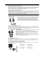
1
Installation
Manual
WITH
WARNING This manual contains information on limitations regarding
product use and function and information on the limitations as to liability
of the manufacturer. The entire manual should be carefully read.
PC5O15
Version 2.2
DLS-1 version 6.5 or later
FCC COMPLIANCE STATEMENT
CAUTION: Changes or modifications not expressly approved by Digital Security Controls Ltd. could void your authority to use this equipment.
This equipment has been tested and found to comply with the limits for a Class B digital device, pursuant to Part 15 of the FCC Rules. These limits are designed to provide reasonable
protection against harmful interference in a residential installation. This equipment generates, uses and can radiate radio frequency energy and, if not installed and used in accordance
with the instructions, may cause harmful interference to radio communications. However, there is no guarantee that interference will not occur in a particular installation. If this equipment
does cause harmful interference to radio or television reception, which can be determined by turning the equipment off and on, the user is encouraged to try to correct the interference
by one or more of the following measures:
• Re-orient the receiving antenna.
• Increase the separation between the equipment and receiver.
• Connect the equipment into an outlet on a circuit different from that to which the receiver is connected.
• Consult the dealer or an experienced radio/television technician for help.
The user may find the following booklet prepared by the FCC useful: “How to Identify and Resolve Radio/Television Interference Problems”. This booklet is available from the U.S.
Government Printing Office, Washington D.C. 20402, Stock # 004-000-00345-4.
IMPORTANT INFORMATION
This equipment complies with Part 68 of the FCC Rules. On the side of this equipment is a label that contains, among other information, the FCC registration number of this equipment.
NOTIFICATION TO TELEPHONE COMPANY The customer shall notify the telephone company of the particular line to which the connection will be made, and provide the FCC
registration number and the ringer equivalence of the protective circuit.
FCC Registration Number: F53CAN-32104-AL-E
REN: 0.6B
USOC Jack: RJ31X
TELEPHONE CONNECTION REQUIREMENTS Except for the telephone company provided ringers, all connections to the telephone network shall be made through standard
plugs and telephone company provided jacks, or equivalent, in such a manner as to allow for easy, immediate disconnection of the terminal equipment. Standard jacks shall be so
arranged that, if the plug connected thereto is withdrawn, no interference to the operation of the equipment at the customer’s premises which remains connected to the telephone network
shall occur by reason of such withdrawal.
INCIDENCE OF HARM Should terminal equipment or protective circuitry cause harm to the telephone network, the telephone company shall, where practicable, notify the customer
that temporary disconnection of service may be required; however, where prior notice is not practicable, the telephone company may temporarily discontinue service if such action is deemed
reasonable in the circumstances. In the case of such temporary discontinuance, the telephone company shall promptly notify the customer and will be given the opportunity to correct
the situation.
ADDITIONAL TELEPHONE COMPANY INFORMATION The security control panel must be properly connected to the telephone line with a USOC RJ-31X telephone
jack.
The FCC prohibits customer-provided terminal equipment be connected to party lines or to be used in conjunction with coin telephone service. Interconnect rules may vary from state
to state.
CHANGES IN TELEPHONE COMPANY EQUIPMENT OR FACILITIES The telephone company may make changes in its communications facilities, equipment, operations or
procedures, where such actions are reasonably required and proper in its business. Should any such changes render the customer’s terminal equipment incompatible with the telephone
company facilities the customer shall be given adequate notice to the effect modifications to maintain uninterrupted service.
RINGER EQUIVALENCE NUMBER (REN) The REN is useful to determine the quantity of devices that you may connect to your telephone line and still have all of those devices
ring when your telephone number is called. In most, but not all areas, the sum of the RENs of all devices connected to one line should not exceed five (5.0). To be certain of the number
of devices that you may connect to your line, you may want to contact your local telephone company.
EQUIPMENT MAINTENANCE FACILITY If you experience trouble with this telephone equipment, please contact the facility indicated below for information on obtaining service
or repairs. The telephone company may ask that you disconnect this equipment from the network until the problem has been corrected or until you are sure that the equipment is not
malfunctioning.
Digital Security Controls Ltd. 160 Washburn St., Lockport, NY 14094
Table of Contents
Section 1: Introduction
Section 5: Program Descriptions
1.1
1.2
1.3
5.1
5.2
5.3
5.4
5.5
5.6
5.7
5.8
5.9
5.10
5.11
5.12
5.13
5.14
5.15
5.16
5.17
5.18
5.19
5.20
5.21
5.22
5.23
5.24
5.25
5.26
5.27
5.28
5.29
5.30
PC5015 Specifications ......................................................... 1
Additional Devices ............................................................... 2
Out of the Box ...................................................................... 4
Section 2: Getting Started
2.1
2.2
2.3
2.4
2.5
2.6
2.7
2.8
2.9
2.10
Installation Steps .................................................................. 5
Terminal Descriptions .......................................................... 5
Keybus Operation and Wiring ............................................. 7
Current Ratings - Modules and Accessories ...................... 7
Assigning Zones to Zone Expanders .................................. 8
Keypad Assignment ............................................................. 9
Enable Supervision .............................................................. 9
Removing Modules ............................................................ 10
Zone Wiring ........................................................................ 10
Keypad Zones .................................................................... 12
Section 3: Keypad Commands
3.1
3.2
3.3
3.4
3.5
3.6
3.7
Access Codes .................................................................... 13
Arming/Disarming .............................................................. 13
Auto Bypass ....................................................................... 14
[✱] Commands ................................................................... 14
Function Keys .................................................................... 17
Global and Partition Keypad Operation ............................ 19
Features Available for the LCD5500Z ............................... 19
Section 4: How to Program
4.1
4.2
4.3
4.4
4.5
How to Enter Installer Programming .................................. 20
Programming Decimal Data ............................................... 20
Programming HEX Data ..................................................... 20
Programming Toggle Option Sections ............................... 21
Viewing Programming ........................................................ 21
Zone Definitions ................................................................. 22
Zone Attributes ................................................................... 23
Communicator - Dialing ..................................................... 24
Communicator - Phone Numbers ...................................... 24
Communicator - Account Numbers ................................... 25
Communicator - Reporting Formats .................................. 25
Communicator – Reporting Codes .................................... 27
Downloading ...................................................................... 28
Partitions/Zone Assignment ............................................... 29
Programmable Outputs ...................................................... 29
Telephone Line Monitor (TLM) ........................................... 32
Siren .................................................................................... 32
Test Transmission ............................................................... 32
Fire, Auxiliary, Panic Keys ................................................. 33
Entry/Exit Delay Options .................................................... 33
Event Buffer ........................................................................ 34
Swinger Shutdown ............................................................. 34
Daylight Savings Time ....................................................... 34
Keypad Backlighting .......................................................... 34
Arming/Disarming Options ................................................ 34
Automatic Arming .............................................................. 35
Keypad Lockout ................................................................. 36
Keypad Blanking ................................................................ 36
Loop Response .................................................................. 36
Keypad Tampers ................................................................ 36
LINKS1000 Cellular Communicator ................................... 36
Module Programming ......................................................... 37
Default (Factory) ................................................................ 37
Installer Lockout ................................................................. 38
Walk Test (Installer) ............................................................ 38
Appendix A: Reporting Codes
39
Appendix B: Zone Reporting Codes
41
Appendix C: Control Panel Wiring Diagram
42
Appendix D: Modules Supported on the
PC5015 v2.2
Inside back cover
LIMITED WARRANTY
Digital Security Controls Ltd. warrants the original purchaser that for a period of twelve
months from the date of purchase, the product shall be free of defects in materials and
workmanship under normal use. During the warranty period, Digital Security Controls
Ltd. shall, at its option, repair or replace any defective product upon return of the product
to its factory, at no charge for labour and materials. Any replacement and/or repaired
parts are warranted for the remainder of the original warranty or ninety (90) days, whichever is longer. The original owner must promptly notify Digital Security Controls Ltd. in
writing that there is defect in material or workmanship, such written notice to be received
in all events prior to expiration of the warranty period.
International Warranty
The warranty for international customers is the same as for any customer within Canada
and the United States, with the exception that Digital Security Controls Ltd. shall not be
responsible for any customs fees, taxes, or VAT that may be due.
Warranty Procedure
To obtain service under this warranty, please return the item(s) in question to the point of
purchase. All authorized distributors and dealers have a warranty program. Anyone returning goods to Digital Security Controls Ltd. must f irst obtain an authorization number. Digital Security Controls Ltd. will not accept any shipment whatsoever for which
prior authorization has not been obtained.
Conditions to Void Warranty
This warranty applies only to defects in parts and workmanship relating to normal use. It
does not cover:
• damage incurred in shipping or handling;
• damage caused by disaster such as f ire, flood, wind, earthquake or lightning;
• damage due to causes beyond the control of Digital Security Controls Ltd. such as
excessive voltage, mechanical shock or water damage;
• damage caused by unauthorized attachment, alterations, modifications or foreign objects;
• damage caused by peripherals (unless such peripherals were supplied by Digital Security Controls Ltd.);
• defects caused by failure to provide a suitable installation environment for the products;
• damage caused by use of the products for purposes other than those for which it was
designed;
• damage from improper maintenance;
• damage arising out of any other abuse, mishandling or improper application of the
products.
Digital Security Controls Ltd.’s liability for failure to repair the product under this warranty after a reasonable number of attempts will be limited to a replacement of the product, as the exclusive remedy for breach of warranty. Under no circumstances shall Digital
Security Controls Ltd. be liable for any special, incidental, or consequential damages
based upon breach of warranty, breach of contract, negligence, strict liability, or any
other legal theory. Such damages include, but are not limited to, loss of profits, loss of
the product or any associated equipment, cost of capital, cost of substitute or replacement equipment, facilities or services, down time, purchaser’s time, the claims of third
parties, including customers, and injury to property.
Disclaimer of Warranties
This warranty contains the entire warranty and shall be in lieu of any and all other
warranties, whether expressed or implied (including all implied warranties of merchantability or fitness for a particular purpose) And of all other obligations or liabilities on the part of Digital Security Controls Ltd. Digital Security Controls Ltd.
neither assumes nor authorizes any other person purporting to act on its behalf to
modify or to change this warranty, nor to assume for it any other warranty or liability concerning this product.
This disclaimer of warranties and limited warranty are governed by the laws of the
province of Ontario, Canada.
WARNING: Digital Security Controls Ltd. recommends that the entire system be completely tested on a regular basis. However, despite frequent testing, and due to, but not
limited to, criminal tampering or electrical disruption, it is possible for this product to
fail to perform as expected.
Installer’s Lockout
Any products returned to DSC which have the Installer’s Lockout option enabled and
exhibit no other problems will be subject to a service charge.
Out of Warranty Repairs
Digital Security Controls Ltd. will at its option repair or replace out-of-warranty products which are returned to its factory according to the following conditions. Anyone
returning goods to Digital Security Controls Ltd. must f irst obtain an authorization number. Digital Security Controls Ltd. will not accept any shipment whatsoever for which
prior authorization has not been obtained.
Products which Digital Security Controls Ltd. determines to be repairable will be repaired
and returned. A set fee which Digital Security Controls Ltd. has predetermined and which
may be revised from time to time, will be charged for each unit repaired.
Products which Digital Security Controls Ltd. determines not to be repairable will be
replaced by the nearest equivalent product available at that time. The current market
price of the replacement product will be charged for each replacement unit.
WARNING
Please Read Carefully
Note to Installers
This warning contains vital information. As the only individual in contact with system users, it is your
responsibility to bring each item in this warning to the attention of the users of this system.
System Failures
This system has been carefully designed to be as effective as possible. There are circumstances, however, involving fire, burglary, or other types of emergencies where it may not provide protection. Any
alarm system of any type may be compromised deliberately or may fail to operate as expected for a
variety of reasons. Some but not all of these reasons may be:
■ Inadequate Installation
A security system must be installed properly in order to provide adequate protection. Every installation
should be evaluated by a security professional to ensure that all access points and areas are covered.
Locks and latches on windows and doors must be secure and operate as intended. Windows, doors,
walls, ceilings and other building materials must be of suff icient strength and construction to provide
the level of protection expected. A reevaluation must be done during and after any construction activity.
An evaluation by the fire and/or police department is highly recommended if this service is available.
■ Criminal Knowledge
This system contains security features which were known to be effective at the time of manufacture. It is
possible for persons with criminal intent to develop techniques which reduce the effectiveness of these
features. It is important that a security system be reviewed periodically to ensure that its features remain
effective and that it be updated or replaced if it is found that it does not provide the protection expected.
■ Access by Intruders
Intruders may enter through an unprotected access point, circumvent a sensing device, evade detection
by moving through an area of insufficient coverage, disconnect a warning device, or interfere with or
prevent the proper operation of the system.
■ Power Failure
Control units, intrusion detectors, smoke detectors and many other security devices require an adequate
power supply for proper operation. If a device operates from batteries, it is possible for the batteries to fail.
Even if the batteries have not failed, they must be charged, in good condition and installed cor rectly. If a
device operates only by AC power, any interruption, however brief, will render that device inoperative
while it does not have power. Power interruptions of any length are often accompanied by voltage fluctuations which may damage electronic equipment such as a security system. After a power interruption has
occurred, immediately conduct a complete system test to ensure that the system operates as intended.
■ Failure of Replaceable Batteries
This system’s wireless transmitters have been designed to provide several years of battery life under normal
conditions. The expected battery life is a function of the device environment, usage and type. Ambient conditions such as high humidity, high or low temperatures, or large temperature fluctuations may reduce the
expected battery life. While each transmitting device has a low battery monitor which identifies when the
batteries need to be replaced, this monitor may fail to operate as expected. Regular testing and maintenance
will keep the system in good operating condition.
■ Compromise of Radio Frequency (Wireless) Devices
Signals may not reach the receiver under all circumstances which could include metal objects placed on or
near the radio path or deliberate jamming or other inadvertent radio signal interference.
■ System Users
A user may not be able to operate a panic or emergency switch possibly due to permanent or temporary
physical disability, inability to reach the device in time, or unfamiliarity with the correct operation. It is
important that all system users be trained in the correct operation of the alarm system and that they
know how to respond when the system indicates an alarm.
■ Smoke Detectors
Smoke detectors that are a part of this system may not properly alert occupants of a fire for a number of
reasons, some of which follow. The smoke detectors may have been improperly installed or positioned.
Smoke may not be able to reach the smoke detectors, such as when the fire is in a chimney, walls or roofs,
or on the other side of closed doors. Smoke detectors may not detect smoke from fires on another level of
the residence or building.
Every fire is different in the amount of smoke produced and the rate of burning. Smoke detectors cannot
sense all types of fires equally well. Smoke detectors may not provide timely warning of fires caused by
carelessness or safety hazards such as smoking in bed, violent explosions, escaping gas, improper storage
of flammable materials, overloaded electrical circuits, children playing with matches or arson.
Even if the smoke detector operates as intended, there may be circumstances when there is insuff icient
warning to allow all occupants to escape in time to avoid injury or death.
■ Motion Detectors
Motion detectors can only detect motion within the designated areas as shown in their respective installation instructions. They cannot discriminate between intruders and intended occupants. Motion detectors do
not provide volumetric area protection. They have multiple beams of detection and motion can only be
detected in unobstructed areas covered by these beams. They cannot detect motion which occurs behind
walls, ceilings, floor, closed doors, glass partitions, glass doors or windows. Any type of tampering whether
intentional or unintentional such as masking, painting, or spraying of any material on the lenses, mirrors,
windows or any other part of the detection system will impair its proper operation.
Passive infrared motion detectors operate by sensing changes in temperature. However their effectiveness can be reduced when the ambient temperature rises near or above body temperature or if there are
intentional or unintentional sources of heat in or near the detection area. Some of these heat sources
could be heaters, radiators, stoves, barbeques, fireplaces, sunlight, steam vents, lighting and so on.
■ Warning Devices
Warning devices such as sirens, bells, horns, or strobes may not warn people or waken someone sleeping if there
is an intervening wall or door. If warning devices are located on a different level of the residence or premise, then
it is less likely that the occupants will be alerted or awakened. Audible warning devices may be interfered with
by other noise sources such as stereos, radios, televisions, air conditioners or other appliances, or passing traffic.
Audible warning devices, however loud, may not be heard by a hearing-impaired person.
■ Telephone Lines
If telephone lines are used to transmit alarms, they may be out of service or busy for certain periods of
time. Also an intruder may cut the telephone line or defeat its operation by more sophisticated means
which may be difficult to detect.
■ Insufficient Time
There may be circumstances when the system will operate as intended, yet the occupants will not be
protected from the emergency due to their inability to respond to the warnings in a timely manner. If the
system is monitored, the response may not occur in time to protect the occupants or their belongings.
■ Component Failure
Although every effort has been made to make this system as reliable as possible, the system may fail to
function as intended due to the failure of a component.
■ Inadequate Testing
Most problems that would prevent an alarm system from operating as intended can be found by regular
testing and maintenance. The complete system should be tested weekly and immediately after a breakin, an attempted break-in, a fire, a storm, an earthquake, an accident, or any kind of construction activity
inside or outside the premises. The testing should include all sensing devices, keypads, consoles, alarm
indicating devices and any other operational devices that are part of the system.
■ Security and Insurance
Regardless of its capabilities, an alarm system is not a substitute for property or life insurance. An alarm
system also is not a substitute for property owners, renters, or other occupants to act prudently to prevent
or minimize the harmful effects of an emergency situation.
System Introduction
S
1.1
E
C
T
I
O
N
1
PC5015 Specifications
Flexible Zone Configuration:
• 8 Fully Programmable Zones
• 38 Access Codes: 32 User, 1 System Master, 2 Partition Master, 2 Duress and 1 maintenance
• Expandable to 32 Zones
• Keypads with zone inputs available (PC5508Z, PC5516Z, PC5532Z, LCD5500Z)
• Hardwired expansion available using the PC5108 Eight Zone Expansion Module and the PC5700 Fire Module
• Wireless expansion available using the PC5132 Wireless Zone Expansion Module (up to 32 wireless
zones, 900MHz, True Spread Spectrum Technology, Fully Supervised)
• Normally Closed, Single EOL, or Double EOL zone supervision
• 2-Wire Smoke Input (via PGM2 input)
• 28 Zone Types, 8 Programmable Zone Options
• 2 Partitions
Audible Alarm Output:
• 700mA Supervised Bell Output (current limited at 3 amps), 12 V DC
• Steady or Pulsed Output
EEPROM Memory:
• Will not lose programming or system status on complete AC and Battery failure
Programmable Outputs:
• Up to 14 Programmable Voltage Outputs, 24 programmable options
• One High Current (300 mA) PGM output with 2-wire smoke detector capability on main panel
• Maximum Loop Current is 1.5 mA when the 2-wire smoke detector configuration is used
• One Low Current (50 mA) PGM output on main panel
• Eight Additional Low Current (50 mA) PGM outputs available using the PC5208 module
• Four High Current (1 Amp) PGM outputs Available Using the PC5204 module
• One PC5204 Output Fully Supervised for Siren Output
Powerful 1.5 Amp Regulated Power Supply:
• 550 mA Auxiliary Supply, 12 VDC
• Positive Temperature Coefficient (PTC) components replace fuses
• Supervision for loss of AC Power, Low Battery
• Internal Clock Locked to AC Power Frequency
Power Requirements:
• Transformer = 16.5 VAC, 40VA
• Battery = 12 volt 4 Ah minimum rechargeable sealed lead acid
Remote Keypad Specifications:
• 8 Different Keypads Available:
- PC5508 (Z ) 8 Zone LED Keypad
- PC5532 (Z ) 32 Zone LED Keypad
- PC5516 (Z ) 16 Zone LED Keypad
- LCD5500 (Z ) Alphanumeric Keypad
• Each Keypad has 5 Fully Programmable Function Keys
• Connect up to 8 Keypads
• Four Wire (Quad) Connection to Keybus
• Built in Piezoelectric Buzzer
• “Z” version keypads have zone input
Digital Communicator Specifications:
• Supports all Major Formats including SIA and Contact ID and Residential Dial
• Split Reporting of Selected Transmissions to Each Telephone Number
• 3 Programmable Phone Numbers
• 2 Account numbers
• Supports LINKS1000 Cellular Communication
• DTMF and Pulse Dialing
• DPDT Line Seizure
• Anti-jam Feature
• Event-Initiated Personal Paging
System Supervision Features
The PC5015 continuously monitors
• AC Power Failure
• Telephone Line Trouble
• Loss of Internal Clock
• Failure to Communicate
a number of possible trouble conditions including:
• Trouble by Zone
• Fire Trouble
• Low Battery Condition
• Bell Output Trouble
• AUX Power Supply Fault
• Tamper by Zone
• Module Fault (Supervisory or Tamper) • Camera Troubles via DLM-4L
1
S
Y
S
T
E
M
I
N
T
R
False Alarm Prevention Features
• Audible Exit Delay
• Audible Exit Fault
• Quick Exit
• Swinger Shutdown
• Cross Zone Alarm
• Burglary-verified timer
• Communication Delay
• Rotating Keypress Buffer
O
D
U
C
T
I
O
N
• Urgency on Entry Delay
• Recent Closing Transmission
• Double Hit Timer
Additional Features
• Auto Arm by Partition at Specified Time each day of the week
• Keypad Activated Alarm Output and Communicator Test
• Keypad Lockout
• Audio Capability using the PC5928 Audio Interface Module which allows local intercom and Central
Station 2-Way Listen in.
• All modules connect to the system via a four wire Keybus up to 1000’/305m from main panel
• Event Buffer can be printed using PC5400 RS232 Serial Interface module
• Supports the Escort5580 Voice Prompt Module with Automation/Lighting Control
• 128 Event Buffer, Time and Date Stamped
• Upload/Download Capability
• Daylight Savings time option
• Downlook support (DLM-4L: v1.0L and PC5108L)
1.2
Additional Devices
In addition to the information below, see the inside back cover for a DSC Module Compatability table.
1.2.1
Keypads
A maximum of eight (8) keypads can be connected to the control panel and can be any combination of
the following listed. Different keypads (with function keys) can be used for different size systems; 8 zone,
16 zone and 32 zone.
PC5508 /PC5508Z
8 zone LED keypad
PC5516 / PC5516Z
16 zone LED keypad
PC5532 / PC5532Z
32 zone LED keypad
LCD5500 /LCD5500Z
LCD keypad
1.2.2
PC5108 Eight Zone Expander Module
Eight zone expander module can be used to increase the number of zones on
the system. Up to 3 modules can be connected to increase the system zones to
a maximum of 32. (See PC5108 Installation Instructions Sheet.)
1.2.3
PC5132 Wireless Receiver Module
The PC5132 Wireless Receiver module can be used to connect up to 32
wireless devices. All devices are spread spectrum, 900 MHz, fully supervised
and use standard ‘AAA’ or ‘AA’ alkaline batteries. (See PC5132 Installation
Manual for details.)
Additional wireless devices are available:
WLS904 Wireless Motion Detector
The wireless Motion Detector can be used in conjunction with the PC5132 Wireless Receiver to include
wireless space protection. The unit comes with four ‘AAA’ batteries.
WLS906 Wireless Smoke Detector
The wireless Smoke Detector can be used in conjunction with the PC5132 Wireless Receiver to include
wireless smoke detection. The unit comes with six ‘AA’ batteries.
WLS907 Wireless Slimline Universal Transmitter
The wireless Slimline Universal Transmitter can be used with the PC5132 Wireless Receiver to add wireless door
or window contacts in a smaller package. The unit comes with three ‘AAA’ batteries and has built-in contacts.
WLS908 Wireless Panic Pendant
The wireless Panic Pendant can be used in conjunction with the PC5132 Wireless Receiver to include
personal wireless protection. The unit comes with 1 mini 12V battery (not user changeable).
2
S
Y
S
T
E
M
I
N
T
R
O
D
U
C
T
I
O
N
WLS909 Wireless Key
The Wireless Key can be used in conjunction with the PC5132 Wireless Receiver to include a simple and
mobile method of arming and disarming the system. The unit comes with three Photo/Electronic 1.5V batteries.
This system can have a maximum of 16 Wireless Keys.
WLS910 Wireless Handheld Keypad
The wireless Handheld Keypad can be used in conjunction with the PC5132 Wireless Receiver to include a
simple and mobile method of arming and disarming the system. The unit comes with three ‘AAA’ batteries.
The system can have a maximum of four wireless Handheld Keypads.
1.2.4
PC5204 Power Supply Output Module
The PC5204 can provide up to 1 Amp of additional power for modules or
devices connected to the control panel. The module requires a 16.5 volt AC 40
VA transformer and 4 AH battery. In addition, the module provides 4 programmable high current voltage outputs. (See PC5204 Installation Instructions for
details.)
1.2.5
PC5208 Eight Low Current Output Module
Adds eight programmable low current outputs (50 mA) to the control. (See
PC5208 Installation Instructions for details.)
1.2.6
Escort5580 Module
This Escort5580 module will turn any touch tone phone into a fully functional
keypad. The module also includes a built-in interface to control up to 32 line
carrier type devices for lighting and temperature control (See Escort5580
Installation Manual for details.)
1.2.7
PC5928 Audio Interface Module (This device is not UL Listed)
The PC5928 Audio Interface module is a simple way to incorporate paging,
intercom, baby listen-in and door answer to the PC5015 control panel. The
module also has built-in two-way voice capability for central station (See
PC5928 Installation Manual for details).
Three additional devices are available: (These devices are not UL Listed)
PC5921 Intercom Audio Station can be used in conjunction with the PC5928 Audio Interface
Module .
PC5921 EXT Door Box Audio Station can be used in conjunction with the PC5928 Audio
Interface Module .
PC5921 EXT/R Door Box Audio Station can be used in conjunction with the PC5928 Audio
Interface Module. The Door Box contains a relay so the normal door bell can be used instead of
the internal one generated by the PC5928 module.
1.2.8
PC5400 Printer Module
This PC5400 Printer Module will allow the panel to print out all events that
occur on the system to any serial printer. All events will be printed with
the Partition, time, date and the event that occurred. (See PC5400 Installation Manual for details.)
1.2.9
LINKS1000 Cellular Communicator
The LINKS1000 Cellular Communicator provides an efficient, cost-effective
method for adding cellular back up. The unit comes in its own cabinet with
antenna and requires a separate battery and transformer (See Section 5.26
“LINKS1000 Cellular Communicator”).
3
S
1.2.10
Y
S
T
E
M
I
N
T
O
D
U
C
T
I
O
N
Downlook Support: PC5108L and DLM-4L v1.0L (This device is not UL Listed)
The PC5108L will expand the control panel’s zone capability by adding eight fully programmable zone
inputs. The module will also act as an interface between the DLM-4L v1.0L Video Transmission module
and the PC5015 v2.2 alarm control panel. The PC5108L is also an 8-camera video switcher.
For more information on either module, see their respective installation manuals.
PC5108L
1.2.11
R
DLM-4L v1.0L
PC5700 Fire Module
This is a zone expansion module with four general purpose zone inputs, two
Class A supervisory waterflow zone inputs, ground fault detection and dualsupervised telephone line inputs.
1.2.12
Cabinets
Several different cabinets are available for the PC5015 modules. They are as follows:
PC5003C Main Control Cabinet for the PC5015 main panel. Dimensions 288mm x 298mm x 78mm /
11.3” x 11.7” x 3” approximately.
PC5002C Cabinet to house the PC5204 Power Supply Output Module. Dimensions 213mm x 235mm x
78mm / 8.4” x 9.25” x 3” approximately.
PC5004C Cabinet to house the Escort5580 Module and PC5400 Printer Module. Dimensions 229mm x
178mm x 65mm / 9” x 7” x 2.6” approximately.
PC5001C Cabinet to house the PC5108 Zone Expander Module and the PC5208 Eight Low Current
Output Module. Dimensions 153mm x 122mm x 38mm / 6” x 4.8” x 1.5” approximately.
PC5001CP Plastic Cabinet to house the PC5108 Zone Expander Module and the PC5208 Eight Low
Current Output Module. Dimensions 146mm x 105mm x 25.5mm / 5.75” x 4.2” x 1” approximately.
1.2.13
Backplates
There are two different backplates available for keypads to locate an Audio Station next to the keypad:
PC55BP1 Backplate
This backplate is to be used when an Audio Station is to be located next to
a keypad. Dimensions 208mm x 115mm x 18mm / 8.2” x 4.5” x 0.25”
approximately.
PC55BP2 Backplate
This backplate is to be used when an Audio Station is to be located next to a
keypad. In addition the backplate will allow you to mount a PC5108 Zone
Expander Module or the PC5208 Eight Low Current Output Module. Dimensions
208mm x 115mm x 18mm / 8.2” x 4.5” x 0.7” approximately.
1.3
Out of the Box
Verify that the following equipment is included in your system:
• one PC5015 main control cabinet
• one PC5015 circuit board
• one PC55XX(Z) / LCD5500(Z) keypad
• one set of manuals (Installation Manual, one Programming Worksheet Manual and one Instruction
Manual for the end user
• one hardware pack consisting of:
- five plastic circuit board standoffs
- seventeen 5600 ohm (5.6K) resistors
- one 2200 ohm (2.2K) resistor
- one 1000 ohm (1K) resistor
4
Getting Started
S
E
C
T
I
O
N
2
The following sections provide a complete description of how to wire and configure devices and zones.
2.1
Installation Steps
The following steps are provided to assist with the installation of the panel. It is suggested that you read over this
section briefly to get an overall understanding of the order of installation. Once this is done carefully work through
each step. Working from this plan will help reduce problems and reduce the overall installation time required.
Step 1
Create a Layout
Draw a rough sketch of the building and include all alarm detection devices, zone expanders, keypads
and all other modules that are required.
Step 2
Mounting the Panel
Locate the panel in a dry area, preferably located near an unswitched AC power source and the incoming
telephone line. Before attaching the cabinet to the wall be sure to press the five circuit board
mounting studs into the cabinet from the back.
Complete all wiring before applying AC or connecting the battery .
Step 3
Wiring the Keybus (Section 2.3)
Wire the Keybus to each of the modules following the guidelines provided.
Step 4
Assigning Zones to Zone Expanders (Section 2.5)
If zone expander modules are being used the modules must be configured so the panel knows which
zones are assigned to each expander. Follow the guideline provided to assign zones to expanders.
Step 5
Zone Wiring (Section 2.9)
Power down the control panel and complete all zone wiring. Follow the guidelines provided in Section 2.9
to connect zones using normally closed loops, single EOL resistor, double EOL resistors, Fire zones and
Keyswitch Arming zones.
Step 6
Completing Wiring
Complete all other wiring including bells or sirens, phone line connections, ground connections or any
other wiring necessary. Follow the guidelines provided in Section 2.2 “Terminal Descriptions”.
Step 7
Power up the Control Panel
Once all zone wiring and Keybus wiring is complete, power up the control panel.
The panel will not power up if only the battery is connected.
Step 8
Keypad Assignment (Section 2.6)
Keypads must be assigned to different addresses to be properly supervised. Follow the guideline provided
in Section 2.6 to assign keypads.
Step 9
Enabling Supervision (Section 2.7)
After all modules have been wired to the Keybus, supervision must be enabled. Once supervision is enabled,
the panel will be able to indicate module communication faults. Follow the guidelines provided in Section 2.7.
Step 10
Programming the System (Sections 4 and 5)
Section 4.0 provides a complete description of how to program the panel. Section 5.0 contains complete
descriptions of the various programmable features, what options are available and how the options function.
The Programming Work Sheets should be filled out completely before attempting to program the system.
Step 11
Testing the System
Test the panel completely to ensure that all features and functions are operating as programmed.
2.2
Terminal Descriptions
AC Terminals - AC
The panel requires a 16.5 volt, 40 VA transformer. Connect the transformer to an unswitched AC source
and connect the transformer to these terminals.
Do not connect the transformer until all other wiring is complete.
Battery Connection
The battery is used to provide back up power in the event of an AC power failure and to provide additional current
when the panel demands exceed the power output of the transformer, such as when the panel is in alarm.
Do not connect the battery until all other wiring is complete.
Connect the RED battery lead to the positive of the battery, the BLACK battery lead to the negative.
5
G
E
T
T
I
N
G
S
T
A
R
T
E
D
Auxiliary Power Terminals - AUX+ and GND
These terminals provide up to 550 mA of additional current at 12 VDC for devices requiring power. Connect
the positive side of any device requiring power to the AUX+ terminal, the negative side to GND. The AUX
output is protected; if too much current is drawn from these terminals (wiring short) the panel will
temporarily shut off the output, until the problem is corrected.
Bell Output Terminals - BELL+ and BELLThese terminals provide up to 3 Amps of current at 12 VDC (with stand-by battery; 700 mA continuous) for
powering bells, sirens, strobes or other warning type equipment. Connect the positive side of any alarm
warning device to BELL+, the negative side to BELL–. The BELL output is protected; if too much current is
drawn from these terminals (wiring short) the BELL PTC will open.
For fire alarm applications, a fire alarm signalling device MUST be used.
The Bell output is supervised. If no alarm warning device is being used connect a 1000 ohm resistor
across BELL+ and BELL– to prevent the panel from displaying a trouble condition (See Section 3.4 “[✱ ]
Commands, [✱ ][2]”).
For UL installations, when a bell or siren is used for fire signaling with a pulsed
cadence, it must be connected between the AUX+ and BELL- terminals. To
maintain bell circuit supervision, do not connect more than one device to the
BELL- terminal. A fire bell or siren used for this application must be UL Listed
and have a current consumption of 400mA or less (e.g. Wheelock MT-12/24-R).
Keybus Terminals - RED, BLK, YEL, GRN
The Keybus is used by the panel to communicate with modules and by modules to communicate with the
panel. Each module has four Keybus terminals that must be connected to the four Keybus terminals on the
panel. For more information, see Section 2.3 “Keybus Operation and Wiring”.
Programmable Outputs - PGM1 and PGM2
Each PGM output is an open collector switch to ground. That is, when the PGM
output is activated by the panel the terminal will switch to ground.
PGM1 can sink up to 50 mA of current. PGMs can be used to activate LEDs or
a small buzzer. Connect the positive side of the LED or buzzer to AUX+, the
negative side to the PGM1.
PGM2 is a high current output (300mA) and operates similar to PGM1. The
CON1 must remain on at all times. If more than 300 mA of current is required a
relay must be used. Refer to the diagram.
Zone Input Terminals - Z1 to Z8
Each detection device must be connected to a zone on the control panel. It is suggested that each zone
have one detection device however it is possible to wire multiple detection devices to the same zone.
For zone wiring specifics, see Section 2.9 “Zone Wiring” .
Telephone Connection Terminals - TIP, RING, T-1, R-1
If a telephone line is required for central station communication or downloading, connect an RJ-31X jack
in the following manner:
• RING - Red Wire _______ Incoming line from
• TIP - Green Wire
telephone company
• R-1 - Grey Wire ________ Outgoing line to
• T-1 - Brown Wire
house telephone(s)
6
G
E
T
T
I
N
G
S
T
A
R
T
E
D
Connect the PC5015 and modules that use the telephone line(s) in the following order:
L
For example, if you are installing a PC5015 with a LINKS1000 and a PC5928 Intercom module, connect the
incoming line to the LINKS1000, then from the LINKS1000 to the PC5015, then from the PC5015 to the
PC5928 Intercom and then from the PC5928 to the house telephones
For proper operation there must be no other telephone equipment connected between the control
panel and the telephone company facilities.
Do not connect the alarm panel communicator to telephone lines intended for use with a FAX machine. These lines may incorporate a voice filter which disconnects the line if anything other than FAX
signals are detected, resulting in incomplete transmissions .
2.3
Keybus Operation and Wiring
The Keybus is used by the panel to communicate with all modules connected and by the modules to talk to
the panel. The RED and BLK terminals are used to provide power while YEL and GRN are clock and data.
The 4 Keybus terminals of the panel must be connected to the 4 Keybus terminals or wires of all modules.
The following conditions apply:
• Keybus should be run in minimum 22 gauge quad (0.5mm), two pair twist preferred
• the modules can be home run to the panel, connected in series or can be T-tapped
• any module can be connected anywhere along the Keybus, you do not need a separate Keybus wire
run for keypads, zone expanders etc.
• no module can be more than 1,000'/305m (in wire length) from the panel
• shielded wire is not necessary unless wires are run in an area that may present excessive RF noise or
interference
Example of Keybus Wiring
NOTE: Module (A) is wired correctly as it is within 1,000'/305m of the
B
panel, in wire distance.
150’
Module (B) is wired correctly as it is within 1,000'/305m of the
C
500’
panel, in wire distance
150’
Module (C) is NOT wired correctly as it is further than 1,000'/
PANEL
A
305m from the panel, in wire distance.
500’
2.4
Current Ratings - Modules and Accessories
In order for the Power 832 system to operate properly, the power output capabilities of the main control
and expansion devices must not be exceeded. Use the data presented below to ensure that no part of
the system is overloaded and cannot function properly.
System Outputs (all 12 V DC)
• PC5015 VAUX: 550 mA. Subtract the listed rating for each keypad, expansion module and accessory
connected to VAUX or Keybus.
BELL: 700 mA. Continuous Rating.
3.0 A. Short Term. Available only with stand-by battery connected.
• PC5204 VAUX: 1.0 A. Continuous Rating. Subtract for each device connected.
3.0 A. Short Term. Available only with stand-by battery connected.
• PC5208 VAUX: 250 mA. Subtract for each device connected. Subtract the total load on this terminal
from the PC5015 VAUX/Keybus output.
• PC5108 VAUX: 100 mA. Subtract for each device connected. Subtract the total load on this terminal
from the PC5015 VAUX/Keybus output.
7
G
E
T
T
I
N
PC5015 Device Ratings (@ 12 VDC)
• LCD5500 Keypad: 50 mA
• PC5532 Keypad: 45 mA
• PC5516 Keypad: 45 mA
• PC5508 Keypad: 45 mA
• LCD5500Z Keypad: 85 mA
• PC5532Z Keypad: 85 mA
• PC5516Z Keypad: 85 mA
• PC5508Z Keypad: 85 mA
• PC5108 Zone Module: 35 mA
• PC5204 Output Module: 20 mA
• PC5108L Downlook Interface: 60 mA
G
S
•
•
•
•
•
•
•
•
•
•
T
A
R
T
E
D
PC5208 Output Module: 50 mA
PC5132 Wireless Module: 125 mA
Escort5580 Module: 150 mA
PC5928 Audio Interface Module: 65 mA
PC5921 Intercom Audio Station: 20 mA
PC5921 EXT Door Box Audio Station: 20 mA
PC5921 EXT/R Door Box Audio Station: 35 mA
PC5400 Printer Module: 65 mA
DLM-4L v1.0L: 180 mA
PC5700 Fire Module: 150 mA
Other Devices
Read the manufacturer’s literature carefully to determine the maximum current requirement (during
activation or alarm) and use this value for loading calculations. Do not allow connected devices to exceed
the system capabilities during any possible operational mode.
2.5
Assigning Zones to Zone Expanders
The main panel contains zones 1 to 8. Additional zone expanders may be added to increase the number
of zones on the system. Each zone expander consists of two groups of 4 zones and each group must be
configured to assign the specific zones to the expander. This is done by setting the jumpers located on
the expander to the proper settings.
Before a zone expander will work properly the jumpers must be set so the panel can determine the
correct zone assignment.
The following are the jumper settings for different zone assignments:
Jumpers
System Zones Assigned
J1/J4
J2/J5
J3/J6
ON
ON
ON
Zones disabled
OFF
ON
ON
Zones disabled
ON
OFF
ON
Zones 09 - 12
OFF
OFF
ON
Zones 13 - 16
ON
ON
OFF
Zones 17 - 20
OFF
ON
OFF
Zones 21 - 24
ON
OFF
OFF
Zones 25 - 28
OFF
OFF
OFF
Zones 29 - 32
J1, J2 and J3 set system zone assignments for expander zones 1-4
J4, J5 and J6 set system zone assignments for expander zones 5-8
The following are diagrams of the PC5108 and PC5700 zone expander modules and where the jumper
switches are located. Refer to the Installation Instructions of each module for more information.
There are two sets of jumpers, one set for the first 4 zones of the expander and one set for the other 4 zones.
In these two diagrams the jumpers settings shown indicate the first group of four zones of the expander
will be zones 9 to 12 and the second group of 4 zones will be 13 to 16. A group of zones can be disabled
if they are not required for the installation.
8
G
2.6
E
T
T
I
N
G
S
T
A
R
T
E
D
Keypad Assignment
There are 8 available addresses for keypads. LED keypads by default are assigned to address 1 while the
LCD5500(Z) is assigned by default to address 8. Keypads can each be assigned to a different address (1
to 8) which offers two advantages. The panel can supervise the keypad connection to indicate a trouble
condition if it is removed. Also keypads can be assigned to operate a specific partition or operate as a
global keypad.
2.6.1
How to Assign Keypads
All keypad assignment must be done at each keypad on the system. When using LCD5500(Z) keypads,
one keypad must remain in address 8. Do not assign more than one keypad to the same address.
To assign a keypad to a address and select the partition it will operate, enter the following:
Step 1 — Enter Installer Programming
Step 2 — Press [000] for Keypad Programming
Step 3 — Press [0] for Partition and Address Assignment
Enter a two digit number to specify the partition and address assignment.
1st digit Enter 0 for Global Keypad;
Enter 1 for Partition 1 Keypad;
Enter 2 for Partition 2 Keypad
2nd digit Enter 1 to 8 for Address Assignment
Press the [#] key twice to exit programming. Continue this procedure at each keypad until all have been
assigned to the correct address.
02.6.2
How to Program Function Keys
Each of the 5 Function Keys on each keypad may be programmed for different operation on each keypad.
Step 1 - Enter Installer Programming.
Step 2 - Press [000] for Keypad Programming.
Step 3 - Enter [1] to [5] to select Function Key to program.
Step 4 - Enter the 2 digit number, [00] to [25] for option.
Step 5 - Continue from Step 3 until all Function Keys are programmed.
Step 6 - Press [#] key twice to exit Installer Programming.
For a complete list of Function Key options See Section 3.5.1 “Function Key Options” .
2.7
Enable Supervision
Once all the Keybus connections have been made, supervision must be enabled so the panel can
indicate a trouble if a module is removed from the system.
To enable supervision, enter the following at any keypad:
Step 1 - Press [✱] [8] [Installer Code] to enter Installer Programming.
Step 2 - Press [902] to enable supervision. The panel will automatically search for all modules on the
system. Once the search (it will take about 1 minute) is complete enter the following to confirm
the modules on the system.
Step 3 - Press [903] to display all modules.
Zone lights will be turned on according to what modules the panel has found on the system. The LCD
keypad will allow you to scroll through the modules. Refer to the following chart:
Light [1] ....... Keypad 1 present
Light [13] ....... Zones 25 to 28 present
Light [2] ....... Keypad 2 present
Light [14] ....... Zones 29 to 32 present
Light [3] ....... Keypad 3 present
Light [15] ....... N/A (not used)
Light [4] ....... Keypad 4 present
Light [16] ....... N/A (not used)
Light [5] ....... Keypad 5 present
Light [17] ....... Module PC5132 present
Light [6] ....... Keypad 6 present
Light [18] ....... Module PC5208 present
Light [7] ....... Keypad 7 present
Light [19] ....... Module PC5204 present
Light [8] ....... Keypad 8 present
Light [20] ....... Module PC5400 present
Light [9] ....... Zones 9 to 12 present
Light [21] ....... Module PC5928 present
Light [10] ....... Zones 13 to 16 present
Light [22] ....... Alternate Communicator present
Light [11] ....... Zones 17 to 20 present
Light [23] ....... DLM-4L v1.0L present
Light [12] ....... Zones 21 to 24 present
Light [24] ....... Escort5580 module present
If a module is connected but does not show as being present, it may be due to any of the following reasons:
• it is not connected to the Keybus
• if there is a Keybus wiring problem
• if the module is more than 1,000'/305m from the panel
• if the module does not have enough power
• if the PC5132 does not have any devices added
9
G
2.8
E
T
T
I
N
G
S
T
A
R
T
E
D
Removing Modules
If a module is no longer required on the system the panel must be told to no longer supervise the module. To
do this remove the module from the Keybus and perform the Enable supervision function again (See Section
2.7 “Enable Supervision”). The panel will see the module has been removed and will no longer supervise it.
2.9
Zone Wiring
For a complete description of the operation of all zone types, please refer to Section 5.1 (“Zone Definitions”).
There are several different ways in which zones may be wired, depending on which programming options
have been selected. The panel can be programmed to supervise normally closed, End of Line, or Double End
of Line loops. Please refer to the following sections to study each type of individually supervised zone wiring.
Any zone programmed for Fire or 24 Hour Supervisory must be wired with a single End of Line (EOL)
resistor regardless of the type of zone wiring supervision selected for the panel (section [013],
options [1] and [2]). See Section 5.1 “Zone Definitions.”
If you change the zone supervision options from DEOL to EOL or from NC to DEOL (section [013],
options [1] or [2]), you should power down the system completely, and then power it back up. If you
do not, the zones may not work correctly.
2.9.1
Normally Closed (NC) Loops
ANY Z
ANY COM
TERMINAL TERMINAL
ANY Z ANY COM
TERMINAL TERMINAL
2 NORMALLY CLOSED
CONTACTS WITH
NO END OF LINE
RESISTOR
NORMALLY CLOSED
CONTACT;
NO END OF LINE
RESISTOR
To enable normally closed loops, programming section [013], option [1] must be ON.
This option should only be selected if Normally Closed (NC) devices/contacts are being used.
○ ○ ○ ○ ○ ○ ○ ○ ○ ○ ○ ○ ○ ○ ○ ○ ○ ○ ○ ○ ○ ○ ○ ○ ○ ○ ○ ○ ○ ○ ○ ○ ○ ○
Normally Closed Loops .......................................... Section [013], Option [1]
○ ○ ○ ○ ○ ○ ○ ○ ○ ○ ○ ○ ○ ○ ○ ○ ○ ○ ○ ○ ○ ○ ○ ○ ○ ○ ○ ○ ○ ○ ○ ○ ○ ○
2.9.2
Single End Of Line (EOL) Resistors
ANY Z
ANY COM
TERMINAL TERMINAL
ANY Z ANY COM
TERMINAL TERMINAL
ANY Z
ANY COM
TERMINAL TERMINAL
ANY Z ANY COM
TERMINALTERMINAL
NORMALLY CLOSED
CONTACT WITH
5600 Ω END OF LINE
RESISTOR
NORMALLY OPEN
CONTACTS WITH
5600 Ω END OF LINE
RESISTOR
1 NORMALLY OPEN
CONTACT AND
1 NORMALLY CLOSED
CONTACT WITH
5600 Ω END OF LINE
RESISTOR
2 NORMALLY OPEN
CONTACT AND
2 NORMALLY CLOSED
CONTACT WITH
5600 Ω END OF LINE
RESISTOR
To enable panel detection of single end of line resistors, programming section [013], options [1] and [2]
must be OFF.
This option should be selected if either Normally Closed (NC) or Normally Open (NO) detection
devices or contacts are being used.
○ ○ ○ ○ ○ ○ ○ ○ ○ ○ ○ ○ ○ ○ ○ ○ ○ ○ ○ ○ ○ ○ ○ ○ ○ ○ ○ ○ ○ ○ ○ ○ ○ ○
End of Line Resistors ............................................. Section [013], Option [1]
Single End of Line Resistors .................................. Section [013], Option [2]
○ ○ ○ ○ ○ ○ ○ ○ ○ ○ ○ ○ ○ ○ ○ ○ ○ ○ ○ ○ ○ ○ ○ ○ ○ ○ ○ ○ ○ ○ ○ ○ ○ ○
2.9.3
Double End of Line (DEOL) Resistors
Double End of Line resistors allow the panel to determine if the zone is in alarm, tampered or faulted.
To enable panel detection of double end of line resistors, programming section [013], option [1] must be
OFF and option [2] must be ON.
ANY Z ANY COM
TERMINAL TERMINAL
ALARM
CONTACT
DOUBLE EOL CIRCUIT
1 NORMALLY CLOSED
CONTACT WITH
5600Ω END OF LINE
RESISTORS
If the Double EOL supervision option is enabled, all hardwire zones must be wired
for Double EOL resistors, except for Fire and 24 Hour Supervisory zones.
Do not wire DEOL resistors on keypad zones.
Do not use DEOL resistors for Fire zones or 24 Hour Supervisory zones. Do not wire
Fire zones to keypad zone terminals if the DEOL supervision option is selected.
This option can only be selected if Normally Closed (NC) detection devices or
contacts are being used. Only one NC contact can be connected to each zone.
10
G
E
T
T
I
N
G
S
T
A
R
T
E
D
The following chart shows zone status under certain conditions:
Loop Resistance
Loop Status
0Ω (shorted wire, loop shorted)
Fault
5600Ω (contact closed)
Secure
Infinite (broken wire, loop open)
Tamper
11200Ω (contact open)
Violated
○ ○ ○ ○ ○ ○ ○ ○ ○ ○ ○ ○ ○ ○ ○ ○ ○ ○ ○ ○ ○ ○ ○ ○ ○ ○ ○ ○ ○ ○ ○ ○ ○ ○
End-of-Line Resistors ............................................. Section [013], Option [1]
Double
End-of-Line Resistors ................................ Section [013], Option [2]
○ ○ ○ ○ ○ ○ ○ ○ ○ ○ ○ ○ ○ ○ ○ ○ ○ ○ ○ ○ ○ ○ ○ ○ ○ ○ ○ ○ ○ ○ ○ ○ ○ ○
2.9.4
Fire Zone Wiring - 4-wire Smoke Detectors
All zones defined as Fire (See Section 5.1 “Zone Definitions”) must be wired according to the following diagram:
For a complete description of how fire zones operate, see Section 5.1 “Zone Definitions”.
2.9.5
Fire Zone Wiring - 2-wire Smoke Detectors
If PGM2 has been programmed for 2-wire Smoke Detector connection (See Section 5.10 “PGM Output”),
the detectors must be wired according to the following diagram:
For a complete description of how fire zones
operate, see Section 5.1 “Zone Definitions”.
If PGM2 is programmed for 2 wire smoke
support, Jumper CON1 on the main board
must be removed.
2.9.6
24-Hr Auxiliary Input Wiring (PGM2)
If PGM2 has been programmed for 24-hour operation, the zone must be wired according to the following
diagram:
If PGM2 is programmed for 24-Hr Auxiliary
Input support, the connector CON1 on the
main board must be removed.
2.9.7
Keyswitch Zone Wiring
Zones may be programmed to be used as keyswitch
arming zones and must be wired according to the
following diagrams:
For a complete description of how keyswitch zones
operate, see Section 5.1 “Zone Definitions”.
Ω
Ω
11
G
E
T
T
I
N
G
S
T
A
R
T
E
D
2.9.8
LINKS Supervisory (24 Hour Supervisory)
When using the LINKS1000 cellular communicator, any main board zone
may be configured for LINKS Supervision. Program this zone as zone type
[09], 24 Hour Supervisory in section [001].
With a 24 Hour Supervisory zone, if the LINKS1000 experiences a trouble, the
zone will be violated, causing the panel to report the event to the central
station. This type of zone always requires a single EOL resistor (5600Ω).
Wire this zone according to the diagram.
2.9.9
LINKS Answer
If the LINKS1000 cellular communicator is being used a zone may be
configured for LINKS Answer to allow downloading to be performed in the
event of phone line failure.
When the LINKS receives a phone call it will activate the RING terminal on the
LINKS circuit board. This terminal can be used to violate a zone programmed
as LINKS Answer (See Section 5.1 “Zone Definitions”), causing the panel to
seize the phone line and begin communication with the downloading
computer.
The zone programmed as LINKS Answer ALWAYS requires a single EOL resistor
(5600Ω) and must be wired according to this diagram.
The LINKS Answer zone is only required for downloading to the panel via the LINKS.
When using the LINKS, Busy Tone Detection must not be used.
Keypad zones cannot be used for 24 Hour Supervisory or LINKS Answer.
2.10
Keypad Zones
Keypads with zone inputs can be connected to devices such as door contacts. This saves you from
running wires back to the control panel for every device.
To install the keypad, open the keypad plastic by removing the screw at the bottom of the unit. Locate the
five terminals on the keypad circuit board. Connect the four Keybus wires from the control panel: the red
wire to R, the black to B, the yellow to Y and the green to G.
To connect the zone, run one wire to the Z terminal and the other to B. For powered devices, use red and
black to supply power to the device. Run the red wire to the R (positive) terminal and the black wire to the
B (negative) terminal.
When using end of line supervision, connect the zone according to one of the configurations outlined in Section
2.8 “Zone Wiring.” End of line resistors must be placed on the device end of the loop, not at the keypad.
Keypad zones do not support
DEOL resistors.
Assigning Keypad Zones
When using keypad zone inputs, each input used must be assigned a zone number in Installer’s Programming.
First, ensure that you have enrolled all installed keypads into the desired addresses. (See Section 2.6
“Keypad Assignment”).
Next, enter programming section [020] to assign the zones. There are eight programming locations in this
section, one for each keypad address. Enter a 2-digit zone number for each of the keypad zones. This
number must be entered in the location corresponding to the keypad to which each zone is connected.
If a keypad zone input is assigned on zone number form 1 to 8, the corresponding zone cannot be
used on the main control panel.
Once the keypad zones are assigned, you must also program zone definitions and zone attributes.
(See also Section 5.1.1 “Assigning Keypad Zones”).
12
Keypad Commands
S
E
C
T
I
O
N
3
All keypads provide complete information and control of the alarm panel. The panel can be completely programmed
via any keypad on the system. LED keypads provide function indicator lights and individual zone indicator lights for
the alarm circuits. The LCD keypad provides function indicator lights and word descriptions for zone status.
The following sections describe how to arm, disarm and perform other keypad functions.
3.1
Access Codes
All 37 access codes have the ability to arm/disarm any Partition(s) it is enabled for and to activate the PGM
Outputs using the [✱][7] commands (See Section 3.4 “[✱] Commands, [✱ ][7]”).
Additional access code attributes are also programmable. Attributes determine what abilities the code will have.
To program each attribute;
1. Enter [✱] [5] [Master Code] [9] to enter the attribute programming mode.
2. Enter the 2-digit number of the access code you want to edit.
3. Enter the attribute number to toggle it on or off.
The programmable attributes are as follows:
• Attribute 1: Partition 1 Operation enabled
• Attribute 2: Partition 2 Operation enabled
• Attribute 3: Zone Bypass enabled
This attribute allows the user to bypass zones.
• Attribute 4: Escort5580 Remote Access
This attribute allows the user to access the security system via the Escort, if installed.
• Attribute 5: Downlook Remote Trigger to Telephone Number 1
For use with the Escort5580 and the PC5108L/DLM-4L (see the PC5108L Installation Manual for details).
• Attribute 6: Downlook Remote Trigger to Telephone Number 2
For use with the Escort5580 and the PC5108L/DLM-4L (see the PC5108L Installation Manual for details).
“Master Code” attributes cannot change. By default, each code has the attributes of the code used to
program it.
The available access codes are as follows:
General Access Codes - Access Codes [01] to [32]
Each access code can be used to arm and disarm the system. Enable any of the access code attributes
to allow access to the above-mentioned functions (access code attributes 1-6).
Duress Codes - Access Codes [33] and [34]
When a Duress Code is used to perform any function the panel will report a Duress Reporting Code (See
Section 5.7 “Communicator - Reporting Codes”) .
Partition Master Codes - Access Codes [41] and [42]
Partition Master Codes can program additional access codes and the Duress Code for their Partition.
System Master Code - Access Code [40]
By default the System Master Code is enabled to operate on both Partitions and can perform any keypad
function. This code can be used to program all access codes as well as the Partition Master Codes and
Duress Codes.
If the Master Code Not Changeable option is enabled the System Master Code can only be changed
using Installer Programming.
For instructions on programming access codes, see the PC5015 Instruction Manual (“Programming
Access Codes”).
○ ○ ○ ○ ○ ○ ○ ○ ○ ○ ○ ○ ○ ○ ○ ○ ○ ○ ○ ○ ○ ○ ○ ○ ○ ○ ○ ○ ○ ○ ○ ○ ○ ○
Code Required for Bypass ..................................... Section [015], Option [5]
Master
Code Not Changeable option .................... Section [015], Option [6]
○ ○ ○ ○ ○ ○ ○ ○ ○ ○ ○ ○ ○ ○ ○ ○ ○ ○ ○ ○ ○ ○ ○ ○ ○ ○ ○ ○ ○ ○ ○ ○ ○ ○
Maintenance Code
The maintenance code can only be used to arm and disarm the system. It cannot be used to bypass
zones or to access the Escort5580. The code can only be programmed in Installer’s Programming.
○ ○ ○ ○ ○ ○ ○ ○ ○ ○ ○ ○ ○ ○ ○ ○ ○ ○ ○ ○ ○ ○ ○ ○ ○
Maintenance Code .................................................. [008]
○ ○ ○ ○ ○ ○ ○ ○ ○ ○ ○ ○ ○ ○ ○ ○ ○ ○ ○ ○ ○ ○ ○ ○ ○
3.2
Arming / Disarming
The system cannot be armed unless the ‘Ready’ light is on. If the ‘Ready’ light is not on make sure all
protected doors and windows are secure and stop movement in areas covered by motion detectors. When
the ‘Ready’ light is on enter any valid Access Code. As each digit is pressed the keypad will beep. If an
incorrect code is entered the keypad will emit a steady 2 second beep to indicate the code was not correct.
13
K
E
Y
P
A
D
C
O
M
M
A
N
D
S
If the code is correct but the ‘Ready’ light was not on the panel will beep six times rapidly followed by a long
two second beep to indicate the system was not Ready. When the correct code is entered and the system is
Ready the panel will beep six times rapidly and the ‘Armed’ light will turn on. Exit the premises through the
designated entry/exit door. Other methods of arming are available (See Section 3.4 “[✱] Commands - [✱] [0]
Quick Arm, [✱ ] [9] Arming Without Entry Delay” and Section 3.5 “Function Keys”).
The PC5015 has a built-in feature called Audible Exit Fault. See Section 5.15 “Entry/Exit Delay Options
for more information.
To disarm the panel enter the premises through the designated entry/exit door. The keypad will emit a steady
beep to warn that you must disarm the system. During the last 10 seconds of entry delay the panel will pulse the
keypad beeper on and off rapidly to warn the entry delay is about to expire. Enter a valid Access Code at the
keypad. If an error is made, re-enter the code correctly. When a correct code is entered the keypad will turn off
the ‘Armed’ light and stop the keypad buzzer. If an alarm occurred while the panel was armed the ‘Memory’ light
and the zones which caused the alarm will be flashing. Press the [#] key to return the keypad to the Ready state.
3.3
Auto Bypass
When the system is armed and any zone or zone(s) on the system have been programmed as Stay/Away
the panel will immediately turn on the ‘Bypass’ light. It will then monitor all zones programmed as Delay 1
and Delay 2. If no delay type zone is violated by the end of the exit delay the panel will bypass all Stay/
Away type zones. The ‘Bypass’ light will remain on to inform the home owner that the interior protection
has been automatically bypassed by the panel. If a delay zone is violated during the exit delay, the Stay/
Away zones will be active after the exit delay expires.
This is a convenience for the user that wishes to arm the panel while at home. The user does not have to
bypass the interior manually.
The user can add the Stay/Away zones back into the system at any time by entering the [✱] [1] keypad
command (See Section 3.4 “[✱] Commands, [✱ ][1] Zone Bypass”).
Other methods of Stay arming are available (See Section 3.5 “Function Keys”).
3.4
[✱] Commands
[✱] [1] Zone Bypassing
The [✱] [1] keypad command can be used to bypass individual zones. It can be used if the user wants to
have access to an area while the Partition is armed or to bypass a defective zone (bad contact, damaged
wiring) until service can be provided. A bypassed zone will not cause an alarm. Instructions on zone
bypassing can be found in the PC5015 Instruction Manual (“Zone Bypassing”). When the partition is
disarmed, all zones bypassed using [✱] [1] will be unbypassed, except for 24-hr zones.
If Code Required for Bypass is enabled an access code will be required to enter the Bypass mode. Only
access codes with the Bypass attribute enabled will be able to bypass zones (See Section 3.4 “[✱]
Commands, [✱] [5]“).
Several features have been added to the [✱][1] zone bypassing menu:
• Bypass Recall: Press [99] while in the [✱][1] menu to recall the last set of bypassed zones.
• Clear Bypasses: Press [00] while in the [✱][1] menu to clear all bypassed zones.
• Bypass Groups: Two programmable bypass groups can be recalled when in the [✱][1] Bypass Menu. To
program a bypass group, select the zones to be bypassed. Press [95] for Group #1, or [96] for Group #2. To
recall these groups, press [✱][1] followed by [91] for Group #1 or [92] for Group #2.
If the Code Required for Bypass option is enabled, access codes 40–42 must be used to access this feature.
For two-partition systems, Bypass Group #1 must be used on Partition 1, and Group #2 on Partition 2.
○ ○ ○ ○ ○ ○ ○ ○ ○ ○ ○ ○ ○ ○ ○ ○ ○ ○ ○ ○ ○ ○ ○ ○ ○ ○ ○ ○ ○ ○ ○ ○ ○ ○
Code
required for bypass ....................................... Section [015], Option [5]
○ ○ ○ ○ ○ ○ ○ ○ ○ ○ ○ ○ ○ ○ ○ ○ ○ ○ ○ ○ ○ ○ ○ ○ ○ ○ ○ ○ ○ ○ ○ ○ ○ ○
[✱
✱ ] [2] Trouble Display
The panel constantly monitors itself for several different trouble conditions. If a trouble condition is
present, the Trouble light will be ON and the keypad will beep twice every 10 seconds. The trouble beep
can be silenced by pressing any key on any keypad. If Bell Squawk on Trouble is enabled (section
[014], option[5]), the bell will squawk every 10 seconds when a trouble condition is present.
To view trouble conditions from an LED keypad:
1. Press [✱] [2].
2. The keypad will flash the Trouble light. The zone indicator lights corresponding to the present trouble
conditions will be ON.
When using an LCD keypad, the trouble conditions will be listed on the display; the user must simply use
the arrow (< >) keys to scroll through the list of present trouble conditions.
Troubles can be viewed while armed using the LCD keypad, provided the keypad is version 2.0 or
later. Older keypads will incorrectly display “Fire Trouble”. If using older LCD keypads, programming
section [013], option [3] as OFF will ensure troubles are displayed correctly.
14
K
E
Y
P
A
D
C
O
M
M
A
N
D
S
The various troubles are described below:
Light
1
Trouble
Service Required: Press [1] to determine the specific trouble. If one of the following zone lights is on,
the corresponding trouble is present:
• Light [1] – Low Battery: Main panel backup battery charge is low (below 11.5 volts under
load).Trouble is restored when the battery charges over 12.5 volts.
• Light [2] – Bell Circuit Trouble: The bell circuit is open (see Section 5.13 “Siren”).
• Light [3] – General System Trouble: The printer connected to the PC5400 Printer module has a fault
and is off-line. There are also 5204 AUX Trouble, 5204 Output 1 Trouble, Camera Trouble and Home
Automation Trouble.
• Light [4] – General System Tamper: Tamper has been detected in a module. Entering and exiting
Installer’s Programming will not reset the system tampers. All tamper conditions must be physically
restored.
• Light [5] – General System Supervisory: The panel has lost communication with a module
connected to the Keybus (see Section 2.6 “Supervision”). The event buffer will log the event.
• Lights [6] – Not used
• Light [7] – PC5204 Low Battery: The PC5204 module has a low backup battery.
• Light [8] - PC5204 AC Failure: The PC5204 module has lost AC power.
2
AC Failure: AC power is no longer being supplied to the control panel. The trouble LED will flash if
an AC Failure is present, if the Trouble Light Flashes if AC Fails option is programmed (section [016],
option [2]). This trouble will not be displayed if the AC Trouble Displayed option is disabled (section
[016], option [1]). See section 5.8 “Communicator Reporting Codes - Maintenance” for information
on AC trouble reporting.
Telephone Line Monitoring Trouble (TLM): There is a trouble with the telephone line (See section
5.12 “Telephone Line Monitor”.) If the system has an alternate communicator, this trouble can be
reported to a monitoring station by programming reporting codes in sections [349] and [350].
Failure to Communicate (FTC): The communicator failed to communicate with any of the programmed
telephone numbers (see section 5.5 “Communicator - Dialing”).
Zone Fault (including Fire Zone): A zone on the system is experiencing trouble, meaning that a zone
could not provide an alarm to the panel if required to do so (if a fire zone is open, or there is a short on
a DEOL zone, or a supervisory fault on a wireless zone). When a zone fault trouble condition occurs,
the keypad(s) on the system will start to beep. Press [5] while in Trouble mode to view the affected zones.
A Fire zone trouble will be generated and displayed in the armed state. A Fire zone trouble will
also restart the trouble beeps from all keypads.
3
4
5
6
7
8
Zone Tamper: A zone configured for Double End Of Line resistor supervision has a tamper condition,
or the tamper switch is open on a wireless device. When a tamper condition occurs, the keypad(s) will start
to beep (if the system is armed, an alarm will occur). Press [6] while in the Trouble mode to view the
affected zones. If a zone is tampered or faulted, it must be fully restored to clear the trouble.
Device Low Battery: A wireless device has a low battery condition. Press [7] one, two, or three times
to view which devices are experiencing battery failure. An LED keypad will indicate battery failure
using zone lights 1 to 8. The following will occur:
# of Keypad displays
beeps
Press [7]
1
Zones with low batteries (LED keypad - zone lights 1 to 32)
Press [7] again
2
Handheld keypads with low batteries (LED keypad - zone lights 1 to 4)
Press [7] again
3
Wireless keys with low batteries (LED keypad - zone lights 1 to 16).
Loss of System Time: When the panel is powered up, the internal clock needs to be set to the correct
time. This trouble is cleared when an attempt is made to reset the clock.
✱ ] [3] Alarm Memory
[✱
The ‘Memory’ light will be on if any alarm occurred during the last armed period or if an alarm occurred
while the panel was disarmed (24 hour zones). Instructions on viewing alarms in memory are located in
the PC5015 Instruction Manual (“Disarming the System”).
[✱
✱ ] [4] Door Chime On/Off
If enabled the keypad will beep 5 times rapidly when a zone is tripped and restored. The panel will only
do this for zones with the Door Chime attribute enabled and if the door chime feature is enabled (See
Section 5.2 “Zone Attributes”) . The door chime feature is explained in greater detail in the PC5015
Instruction Manual (“Door Chime Feature”).
15
K
E
Y
P
A
D
C
O
M
M
A
N
D
S
[✱
✱ ] [5] Programming Access Codes
All 37 access codes are programmed in this section. For instructions on programming access codes, see
the PC5015 Instruction Manual (“Programming Access Codes”).
✱ ] [6] User Functions
[✱
To program user functions, perform the following:
1. Press [✱] [6] [Master Code]. The keypad will flash the ‘Program’ light.
2. Press the number [1] to [5] for the item to be programmed.
• [1] - Time and Date
See the PC5015 Instruction Manual for instructions on setting the time and date (“Setting the Time and Date”).
• [2] - Auto-Arm Enable/Disable
Enter [✱] [6] [2] to enable (three keypad beeps) or disable (one long beep) the auto-arm feature.
• [3] - Auto-Arm Schedule
Enter [✱][6][3] to change the auto-arm time for each day of the week.
Scroll to the day of the week you want to change, or enter the number of the day (1-7 for Sunday to
Saturday). On an LED keypad zone lights 1-7 will represent Sunday to Saturday.
When you have selected a day, enter the auto-arm time in 24-hour format (i.e. enter a 4-digit number in
[hhmm] format).
The system will return you to the day selection menu. Scroll to the next day you want to program, or to
exit auto-arm programming, press [#].
Only LCD5500 v2.0 or greater keypads support the [✱][6][3] menu option.
• [4] - System Test
When [4] is pressed the panel will perform the following. For step-by-step instructions on performing a
system test, see the PC5015 Instruction Manual (“Full System Test”):
- sound the alarm output for two seconds
- light all lights on the keypad
- sound the keypad buzzer for two seconds
- test the main panel / PC5204 battery
- send a System Test Reporting code, if programmed (See Section 5.7 “Communicator - Reporting Codes”).
• [5] - Enable DLS (Downloading)
When [5] is pressed the panel will turn on the downloading option for 6 hours. During this time the panel
will answer incoming downloading calls (See Section 5.8 “Downloading”).
• [6] – User Initiated Call-Up
When [6] is pressed, the panel will initiate a call to the downloading computer.
LCD Keypad User Functions
Additional features are available using on the LCD keypad. These features do not have numbers
assigned. Use the arrow keys (< >) to scroll through the [✱] [6] menu and press the [✱] key to select the
following commands.
• View Event Buffer
Buffer: The 128 Event Buffer can be viewed through any LCD keypad (See Section 5.16.1
“Viewing the Event Buffer Through the LCD Keypad”).
• Brightness Control
Control: When this option is selected the keypad will allow you to scroll through 10 different
backlight level options. Use the arrow keys (<>) to scroll to the desired backlight level and press the
[#] key to exit.
• Contrast Control
Control: When this option is selected the keypad will allow you to scroll through 10 different
contrast level options. Use the arrow keys (<>) to scroll to the desired contrast level and press the [#]
key to exit.
• Keypad Buzzer Control
Control: When this option is selected the keypad will allow you to scroll through 21
different keypad sounder tone options. Use the arrow keys (<>) to scroll to the desired keypad beeper
level and press the [#] key to exit. This function can be achieved on LED keypads by holding the [✱] key.
[✱
✱ ] [7] Command Output Functions
There are four output functions available to the user. Entering [✱] [7] [1-4] [Access Code, if required] will
activate any output programmed for options [19]-[22] (respectively). Each function can be performed
when the system is either armed or disarmed.
For more information regarding these output types, see Section 5.10 “PGM Output Options.”
✱ ] [8] Installer Programming
[✱
Enter [✱][8] followed by the Installer Code to enter Installer Programming (See Section 4.0 “How to Program”).
✱ ] [9] Arming Without Entry Delay
[✱
When a Partition is armed with the [✱][9] command the panel will remove the entry delay from the
partition. After the exit delay, Delay 1 and Delay 2 type zones will be instant and Stay/ Away zones will
remain bypassed. (See Section 5.1 “Zone Definitions”).
16
K
E
Y
P
A
D
C
O
M
M
A
N
D
S
For more information regarding this feature, see the PC5015 Instruction Manual (“Alternate Arming
Methods – Arming Without Entry Delay”).
The entry delay can be activated/deactivated at any time while the system is armed by pressing [✱][9].
[✱
✱ ] [0] Quick Arm
If the Quick Arm Enable option is enabled the panel can be armed by entering [✱][0]. This is a useful
method of arming a Partition when someone without a access code will be required to arm a Partition.
The Quick Arm feature must be enabled in order for the Stay/Away function keys to operate as
intended. If the feature is not enabled, the user will be required to enter their access code after
pressing the Stay or Away function key in order to arm the system in the stay or away mode.
[✱
✱ ] [0] Quick Exit
Quick Exit will allow someone to leave an armed premise through a Delay type zone without having to
disarm and rearm the system.
When [✱][0] is entered, if the Quick Exit Enabled option is enabled, the panel will provide a two minute
window to exit. During this time the panel will ignore the first activation of a Delay type zone. When the
Delay zone is secured the panel will end the two minute time period.
If a second Delay zone is tripped, or if the zone is not restored after two minutes, the panel will start entry delay.
If Quick Exit is used on a partitioned system, Keypad Blanking and Access Code Required to Remove
Blanking should be enabled.
○ ○ ○ ○ ○ ○ ○ ○ ○ ○ ○ ○ ○ ○ ○ ○ ○ ○ ○ ○ ○ ○ ○ ○ ○ ○ ○ ○ ○ ○ ○ ○ ○ ○
Quick Arm Enable ................................................... Section [015], Option [4]
Quick
Exit Enable ................................................... Section [015], Option [3]
○ ○ ○ ○ ○ ○ ○ ○ ○ ○ ○ ○ ○ ○ ○ ○ ○ ○ ○ ○ ○ ○ ○ ○ ○ ○ ○ ○ ○ ○ ○ ○ ○ ○
3.5
Function Keys
There are five function keys on the PC5015 keypads labelled Stay, Away, Chime, Reset and Exit. The operation
of these keys is described below. The function is activated by pressing and holding the key for 2 seconds.
“Stay” - Stay Arm
Arms the partition to which the keypad is assigned. All Stay/Away type zones will be automatically
bypassed. Delay type zones will provide entry and exit delay. The Quick Arm feature must be enabled for
this key to function (Section [015], Option [4]). If Quick Arming is not enabled, the user must enter their
access code after pressing the function key in order to arm the system in the Stay mode.
“Away” - Away Arm
Arms the partition to which the keypad is assigned. All Stay/Away type zones will be active at the end of
the exit delay. Delay type zones will provide entry and exit delay. The Quick Arm feature must be enabled
for this key to function (Section [015], option [4]). If Quick Arming is not enabled, the user must enter their
access code after pressing the function key in order to arm the system in the Away mode.
“Chime” - Door Chime On/Off
Pressing the key will toggle the Door Chime feature ON or OFF. One solid beep means the feature has
been disabled, three short beeps means it has been enabled.
“Reset” - Reset Smoke Detectors
Pressing this key will cause the panel to activate for 5 seconds any output programmed as Sensor Reset.
(See Section 3.4 “[ ✱] Commands, [ ✱][7][2]”).
“Exit” - Activate Quick Exit
Pressing this key will cause the panel to activate the Quick Exit feature (See Section 3.4 “[✱] Commands, [✱][0]”).
3.5.1
Function Key Options
The following is a list of Function Key options:
[00] - Null Key
The key is not used and will perform no function when pressed.
[01] - Select Partition 1
Provides an easy way to select Partition 1 operation from a Partition 2 keypad. This is the same as
pressing and holding the [#] key then pressing and holding the [1] key to select Partition 1 from a Partition
2 keypad (See Section 3.6 “Global and Partition Keypad Operation”).
[02] - Select Partition 2
Provides an easy way to select Partition 2 operation from a Partition 1 keypad. This is the same as
pressing and holding the [#] key then pressing and holding the [2] key to select Partition 2 from a Partition
1 keypad (See Section 3.6 “Global and Partition Keypad Operation”).
[03] - Stay Arm
Same as described in Function Keys - Section 3.5.
17
K
E
Y
P
A
D
C
O
M
M
A
N
D
S
[04] - Away Arm
Same as described in Function Keys - Section 3.5.
[05] - [✱]+[9] No-Entry Delay Arm
After this function key is pressed the user must enter a valid access code. The Partition will arm and
remove entry delay from the partition when the exit delay expires (See Section 3.4 “[✱] Commands, [✱ ] [9]
Arming without entry delay”).
[06] - [✱]+[4] Door Chime On/Off
This function key provides the user a simple method for turning the Door Chime feature on and off (See
Section 3.4 “[✱ ] Commands, [✱ ] [4] Door chime on/off”) .
[07] - [✱]+[6]...[4] System Test
This function key provides the user with a simple method for testing the system (See Section 3.4 “[✱]
Commands, [✱ ] [6] User functions”). A valid Master Code is required to perform this command.
[08] - [✱]+[1] Bypass Mode
This function key provides the user with a simple method for entering the Bypass Mode. If a access code
is required it must be entered before bypassing can be performed (See Section 3.4 “[✱ ] Commands, [✱]
[1] Zone Bypass”).
[09] - [✱]+[2] Trouble Display
This function key provides the user with a simple method for entering the Trouble Display Mode (See
Section 3.4 “[✱ ] Commands, [✱]+[2] Trouble display”).
[10] - [✱]+[3] Alarm Memory
This function key provides the user with a simple method for entering the Alarm Memory Display Mode
(See Section 3.4 “[✱] Commands, [✱ ] [3] Alarm memory”).
[11] - [✱]+[5] Programming Access Codes
This function key provides the user with a simple method for programming access codes. After this key is
pressed a valid System Master or Partition Master will have to be entered before the panel will allow
programming to be performed (See Section 3.4 “[✱] Commands, [✱ ] [5] Programming Access Codes”).
[12] - [✱]+[6] User Functions
This function key provides the user with a simple method for programming User Functions. After this key
is pressed a valid System Master or Partition Master must be entered before the panel will allow User
Functions to be performed (See Section 3.4 “[✱ ] Commands, [✱ ] [6] User functions”).
[13] - [✱]+[7]+[1] Command Output Option 1
This function key provides the user with a simple method for activating a PGM Output programmed as
Command Output Option 1 (See Section 5.10 “PGM Outputs”) . By default, after this key is pressed a valid
access code must be entered (See Section 3.4 “[✱] Commands, [✱ ] [7] Command output functions”).
[14] - [✱]+[7]+[2] Smoke Detector Reset
This function key provides the user with a simple method for activating a PGM output programmed as
either option [03] Sensor Reset, [04] 2-wire Smoke Support or [20] Command Output option 2.
[15] - General Voice Prompt Help
This feature can only be programmed if both the Escort5580 and the PC5928 Audio Matrix module are
being used.
When the function key is pressed, the intercoms will perform a Help page. The user must then press the
Page/Answer button on any intercom station to begin the help session with the Escort.
For more information, please refer to the PC5928 Installation Manual.
[16] - [✱]+[0] Quick Exit
Same as described in Function Keys - Section 3.5.
[17] - [✱]+[1] Reactivate Stay/Away Zones
This function key provides the user with a simple method for adding Stay/Away zones back into the
system (see Section 3.4 “[✱] Commands, [✱ ] [1] Reactivate Stay/Away zones”).
[18] Identified Voice Prompt Help
This feature can only be programmed if both the Escort5580 and the PC5928 Audio Matrix module are
being used.
When the function key is pressed, the Escort will begin a help session from the intercom station
programmed as closest to the keypad. In order for this option to function, you must program PC5928
Section [802], subsection [14] “Keypad Port Assignments.” For more information, please refer to the
PC5928 Installation Manual.
Note: This function key cannot be programmed for PC55XXZ LED keypads with software version 1.0.
[19] - [✱]+[7]+[3] Command Output 3
[21] - [✱]+[7]+[4] Command Output 4
Function Keys [19] and [21] provide the user with a simple method of activating an output programmed
as Command Output Option 3 or 4.
18
K
E
Y
P
A
D
C
O
M
M
A
N
D
S
[22] - Active Camera Monitor Selection
This function key is for use with the PC5108L Downlook Interface/Camera Monitor Module. For instructions
on the function key use, see the PC5108L Installation Manual.
[23] - Bypass Recall
Pressing this function key will recall the last group of bypassed zones. The function key will follow the
Code Required for Bypass option. If the option is enabled, a valid access code with the Bypass attribute
enabled must be entered after the function key is pressed. For instructions on zone bypassing, see the
PC5015 Instruction Manual.
[24] - Recall Bypass Group #1
This function key will recall zones in Bypass Group #1. This group is programmed by the user in the [*][1]
Bypass menu. The function key will follow the Code Required for Bypass option. If the option is enabled, a
valid access code with the Bypass attribute enabled must be entered after the function key is pressed.
For instructions on zone bypassing and programming Bypass Groups, see the PC5015 Instruction
Manual.
[25] - Recall Bypass Group #2
This function key operates similar to function key [24] but will recall zones in Bypass Group #2. For
instructions on zone bypassing and programming Bypass Groups, see the PC5015 Instruction Manual.
3.6
Global and Partition Keypad Operation
A global keypad will not display any information (the trouble LED will light if a trouble condition is present)
until a partition is selected. To select a partition the user must press and hold the [1] key for Partition 1 or
the [2] key for Partition 2 for two seconds. The keypad will then display the status of the selected partition
and allow normal operation.
A Partition keypad will display the status of the Partition for which it has been programmed. A user with
access to both partitions may temporarily assign the keypad to the other partition to gain access. To do
this the user must first press and hold the [#] key for two seconds. The keypad will go blank. The user
must then press and hold the [1] key for Partition 1 or the [2] key for Partition 2 for two seconds. The
keypad will then display the status of the selected partition and allow normal access.
3.7
Features Available for the LCD5500Z
These features are only available for LCD5500Z keypads with zone inputs:
Automatic Scrolling of Alarms in Memory
The LCD5500Z keypad allows automatic scrolling through alarms in memory while the keypad is idle. This
feature, if enabled, will override the clock display. This option can be programmed in LCD programming
section [66], option [4].
24 Hour Time Display Option
The LCD5500Z can be programmed to display time using a 24- hour clock, instead of a 12-hour, a.m./
p.m. clock. This option can be programmed in LCD programming section [66], option [3].
Keypad Zones
See section 2.10 “Keypad Zones”.
Viewing Troubles While Armed
See section 3.4 “[✱][2] Trouble Display” for information on how to view troubles.
Backlighting Boost (available for all zone input keypads)
The LCD5500Z and PC55XXZ zone input keypads will provide extra number pad lighting when any key is
pressed. The backlighting boost will last for an additional 30 seconds after the last keypress.
Prompts for the following features are only supported by LCD5500(Z) v2.X:
• Downlook Support (DLM-4L/PC5108L): Active Camera Monitor Selection, Remote Trigger
• Auto Arm features: Late to Close, Auto Arm Postpone/Cancel, Auto Arm by day
• Bypass groups
19
How to Program
S
E
C
T
I
O
N
4
The following section of the manual describes how to enter Installer Programming and how to program the various
sections.
It is extremely important that you read the following section of the manual to completely understand how to
program the panel.
4.1
How to Enter Installer Programming
Installer Programming is used to program all communicator and panel options. The Installer Code is
[5015] at default but should be changed to prevent unauthorized access to programming.
Once the Installer’s Mode is exited, the system will reset. This will take 15 seconds. Do not attempt to
perform any system function during this reset period. In addition, all outputs will return to their
normal, deactivated state (or activated if inverted).
LED Keypad
Step 1 From any keypad enter [✱][8][Installer Code].
• The ‘Program’ light will flash to indicate you are in programming
• The ‘Armed’ light will turn on to indicate the panel is waiting for the 3 digit Section number to
program
Step 2 Enter the 3 digit Section number you want to program.
• The Armed light will turn off
• The Ready light will turn on to indicate the panel is ready for the information for the selected
Section
If the 3 digit section number entered is not valid or the module that pertains to the Section is not
present, the keypad will sound a 2 second beep or error tone.
LCD Keypad
Step 1 From any keypad enter [✱][8][Installer Code].
The Keypad will display ‘Enter Section’ followed by three dashes.
Step 2 Enter the 3 digit Section number you want to program.
The keypad will now display information for the section entered.
○ ○ ○ ○ ○ ○ ○ ○ ○ ○ ○ ○ ○ ○ ○ ○ ○ ○ ○ ○ ○ ○ ○ ○ ○ ○ ○ ○ ○
Installer
Code .......................................................... Section [006]
○ ○ ○ ○ ○ ○ ○ ○ ○ ○ ○ ○ ○ ○ ○ ○ ○ ○ ○ ○ ○ ○ ○ ○ ○ ○ ○ ○ ○
4.2
Programming Decimal Data
When the Ready light is ON the panel is waiting for the information to be programmed for the selected
Section. Enter the information written in the boxes for the Section found in the Programming Worksheets.
If a digit is entered for each program box in a Section the panel will automatically exit from the Section. It
will turn OFF the Ready light and turn the Armed light back ON.
You can also press the [#] key to exit a Section before entering data for every box. This is handy if you
only need to change the first few program boxes. All other locations in the Section will remain unchanged.
If the [#] key is pressed the panel will turn OFF the Ready light, turn ON the Armed light and exit you from
the Section.
4.3
Programming HEX Data
On occasion, hexadecimal (HEX) digits may be required. To program a HEX digit press the [✱] key. The
panel will enter HEX programming and Ready light will begin to flash.
The following table indicates which number should be pressed to enter the corresponding HEX digit:
1=A
2=B
3=C
4=D
5=E
6=F
After the correct HEX digit is entered the Ready light will continue to flash. If another HEX digit is required
press the corresponding number. If a decimal digit is required press the [✱] key again. The Ready light
will turn on solid and the panel will return to regular decimal programming.
It is important to watch the Ready light. If the light is flashing any number you enter will be programmed as the HEX equivalent.
Example: To enter ‘C1’ for a closing by user 1, you would enter [✱] [3] [✱], [1]
[✱] to enter Hexadecimal mode (Ready light flashes)
[3] to enter C
[✱] to return to decimal mode (Ready light is solid)
20
H
O
W
T
O
P
R
O
G
R
A
M
[1] to enter digit 1
If you enter information into a section and make a mistake, press the [#] key to exit the section. Select that
section again and re-enter the information correctly.
If you are using a pulse communications format, a decimal zero [0] does not transmit. Programming a
zero [0] tells the panel not to send any pulses for that digit. Decimal zero [0] is a filler digit. To make a
zero [0] transmit, it must be programmed as a Hexadecimal ‘A’.
Example: for the three digit account number ‘403’, you would enter [4], [✱] [1] [✱] [3], [0].
[4] to enter the digit 4
[✱] to enter Hexadecimal mode (Ready light flashes)
[1] to enter A
[✱] to return to decimal mode (Ready light is solid)
[3] to enter the digit 3
[0] to enter the digit 0 as a filler digit.
4.4
Programming Toggle Option Sections
Some Sections contain several toggle options. The panel will use zone lights 1 through 8 to indicate if the
different options are enabled or disabled. Refer to the Programming Worksheets to determine what each
option represents and whether the light should be ON or OFF for your application.
Press the number corresponding to the option to toggle the light ON or OFF.
Once all the toggle options have been selected correctly press the [#] key to exit the Section and save
the changes. The panel will turn off the Ready light and turn on the Armed light.
4.5
Viewing Programming
4.5.1
LED Keypads
Any program Section can be viewed through the keypad. When a Section is entered the keypad will
immediately display the first digit of information programmed in that Section.
The keypad displays the information using a binary format where:
Zone Light 1 = 1
Zone Light 2 = 2
Zone Light 3 = 4
Zone Light 4 = 8
Add up the values for the zone lights to determine the number displayed (for example, no zone lights = 0,
all 4 zone lights = 15 HEX ‘F’).
Press any of the Emergency Keys (Fire, Auxiliary or Panic) to advance to the next digit. When all the digits
in a Section have been viewed the panel will exit the Section, turn off the Ready Light, turn on the Armed
light and wait for the next three digit Section number to be entered. If the [#] key is pressed the panel will
also exit the Section.
4.5.2
LCD Keypad
Any program section can be viewed through the keypad. Depending on the section entered, the LCD will
display the information differently as below:
Sections Entered
LCD Display
Phone number ..................... Entire phone number
Partition identifier code ....... Entire partition identifier code
Toggle option ...................... Entire section (all options)
Reporting code ................... Each 2-digit reporting code at a time
Use the arrow keys (<>) to scroll through the data being displayed.
Scroll past the end of the data displayed or press the [#] key to exit the Section.
21
Program Descriptions
S
E
C
T
I
O
N
5
The following section explains all the programmable features including how the feature operates, options that
pertain to the feature and a summary of program locations that require programming.
5.1
Zone Definitions
These sections will allow you to select how each of the 32 zones will operate. Each zone requires a 2
digit entry.
In addition to selecting how each zone will operate, attributes may be programmed by zone (See
Section 5.2 “Zone Attributes”).
[00]
Null Zone The zone will not operate in any way. Zones that are not used should be programmed as Null zones.
[01]
Delay 1 Zone If this zone is violated when the panel is armed it will provide entry delay. The keypad
buzzer will sound to warn the user that the system must be disarmed. If the panel is not disarmed
before the entry delay expires an alarm will be generated. Typically this type of zone will be used for
the front door, back door or any other entry/exit point. Refer to Section [005], “System Times”, to
program the Delay 1 zone entry delay time.
[02]
Delay 2 Zone This zone type operates the same as the Delay 1 zone option but can provide a different
entry delay. Typically this zone will be used for a garage door. Refer to Section [005], “System Times”, to
program the Delay 2 zone entry delay.
[03]
Instant Zone If this zone type is violated when the panel is armed it will cause an instant alarm. Typically
this zone is used for windows, patio doors or other perimeter type zones.
[04]
Interior Zone If this type of zone is violated when the panel is armed it will provide entry if a delay type
zone was violated first. Otherwise it will cause an instant alarm. Typically this zone is used for interior
protection devices, such as motion detectors.
[05]
Interior Stay / Away Zone This zone type works the same as the Interior zone type with one exception.
The zone will be automatically bypassed under the following conditions:
• the panel is armed in the Stay Mode (See Section 3.5 “Function Keys”)
• the panel is armed without entry delay (See Section 3.4 “[✱] Commands, [✱ ] [9]”)
• the panel is armed with an access code and during the exit delay a Delay type zone is NOT tripped
The automatic bypass avoids having the user manually bypass interior type zones when arming at home.
If automatically bypassed, the user can reactivate the zones by entering the [✱][1] command (See
Section 3.4 “[✱ ] Commands, [✱][1] Zone Bypass”) . Typically this zone is used for interior protection
devices, such as motion detectors. Stay/Away zones should not be programmed as global zones.
[06]
Delay Stay / Away Zone This zone type will operate the same as the Interior Stay / Away zone type except
that it will always provide entry delay. Typically this zone is used for interior protection devices, such as
motion detectors and will help prevent false alarms since it will always provide the user the entry delay
time to turn off the panel. Stay/Away zones should not be programmed as global zones.
[07]
Delayed 24 Hour Fire Zone If this zone is violated the alarm output will immediately activate but the
communicator will be delayed for 30 seconds. If during the 30 second delay the user presses any key on
any keypad the alarm output and communicator will be delayed an additional 90 seconds, providing the
user time to correct the problem. If after the 90 second delay the zone is still violated the process will
begin again; the alarm output will be activated but the communication will be delayed 30 seconds.
If the user does not press a key, after 30 seconds the alarm output will latch and the panel will communicate.
The alarm will sound for the Bell Cutoff time programmed in Section [005], or can be programmed to sound
until a valid code is entered, Section [014], Option [8]”.
PGM outputs programmed as [10] “Latched System Event” will only activate after the Delayed 24 Hour
Fire zone has latched.
If a second Fire type zone is violated or the Fire keys are pressed during the delay time the panel will
latch the alarm output and communicate immediately.
Do not wire Fire zones on keypad zone terminals if the DEOL supervision option is enabled for the
panel (section [013], option [2]).
Do not program fire zones for Downlook operation.
If a delayed Fire zone is violated it will be displayed on all keypads and can be delayed at any keypad.
Typically this zone is used for latching smoke detectors.
[08]
Standard 24 Hour Fire Zone When violated the panel will immediately latch the alarm output and
communicate to central station. The alarm will sound for the Bell Cutoff time programmed in Section [005], or
can be programmed to sound until a valid code is entered, Section [014], Option [8]”.
If a Fire zone is violated it will be displayed on all keypads. Typically this zone is used for pull stations.
Do not wire Fire zones on keypad zone terminals if the DEOL supervision option is enabled for the
panel (section [013], option [2]).
Do not program fire zones for Downlook operation.
22
P
[09]
R
O
G
R
A
M
D
E
S
C
R
I
P
T
I
O
N
S
24 Hour Supervisory Zone If this zone is violated, whether armed or disarmed, the panel will report to
the central station, and log the zone fault. This zone gives a silent alarm by default.
Do not wire 24-Hour Supervisory zones on keypad zone terminals.
24 Hour Supervisory Buzzer Zone Whether armed or disarmed, when this zone type is violated the
panel will immediately latch the keypad buzzer until a valid access code is entered and will communicate
immediately to the central station.
[11]
24 Hour Burglary Zone If this zone is violated, whether armed or disarmed, the panel will immediately
latch the alarm output and communicate to the central station. The alarm will sound for the Bell Cutoff time
programmed in Section [005] “System Times” or until a valid access code is entered.
[12] -[20] The following zone definitions operate similar to the 24 Hour Burglary except for System Event output type
and SIA identifier:
[12] 24 Hour Holdup Zone
[15] 24 Hour Medical Zone
[18] For future use
[13] 24 Hour Gas Zone
[16] 24 Hour Panic Zone
[19] 24 Hour Water Flow Zone
[14] 24 Hour Heat Zone
[17] 24 Hour Emergency Zone
[20] 24 Hour Freezer Zone
[10]
[21]
[22]
[23]
NOTES: [12] 24 Hour Holdup zones give a silent alarm by default.
Use fire zones for sprinklers.
24 Hour Latching Tamper If this zone is violated the installer must enter Installer Programming before
the panel will allow either Partition to be armed. The bell output will also activate for the programmed time
and the panel will communicate the alarm.
Momentary Keyswitch Arm Zone Momentary violation of this zone will alternately arm/disarm the
Partition the zone is assigned to. This zone type should not be programmed as global.
Maintained Keyswitch Arm Zone When this zone is violated, the partition it is assigned to will arm.
When this zone is secured, the partition will disarm. This zone should not be programmed as global zone.
Do not program wireless zones as [21] or [22] Keyswitch or as [24] LINKS Answer zones.
[24]
LINKS Answer Zone If the LINKS1000 cellular communicator is being used it is possible to perform
downloading through the unit if the phone line is disconnected. If this is required connect the RING
terminal of the LINKS1000 to this zone. Refer to the LINKS1000 Installation sheet for more information.
Do not wire LINKS Answer zones on keypad zone terminals.
[25]
Interior Delay Zone When the system is fully armed (ie. away armed), this zone will, as is standard, follow
the exit delay. It will also follow the entrance delay, provided that a delay zone is first tripped. If the delay
zone is not tripped first, a zone defined as “Interior Delay” will go into alarm instantly. When the system is
at-home or stay armed this zone will be active, but when it is tripped, it will initiate the entrance delay.
[26]
24 Hour Non-Alarm This zone type will be active at all times but will not cause an alarm.
This zone type shall not be used for Downlook-initiating zones (DLM-4L v1.0L) .
[87]
Delayed 24 Hour Fire (Wireless) This zone type operates the same as [07] Delayed 24 Hour Fire Zone
and must be used if the smoke detector is wireless.
Standard 24 Hour Fire (Wireless) This zone type operates the same as [08] Standard 24 Hour Fire
Zone and must be used if the smoke detector is wireless.
[88]
5.1.1
Assigning Keypad Zones
Each keypad has a zone input to which a device—such as a door contact—can be connected. (See
Section 2.12 “Keypad Zones” for wiring information.)
Once the keypad zones are installed, assign the zone in programming section [020] Keypad Zone
Assignments.
Enter the 2 digit zone designated for each keypad (address) from 01-32.
○ ○ ○ ○ ○ ○ ○ ○ ○ ○ ○ ○ ○ ○ ○ ○ ○ ○ ○ ○ ○ ○ ○ ○ ○
Keypad Zone Assignments .................................... [020]
○ ○ ○ ○ ○ ○ ○ ○ ○ ○ ○ ○ ○ ○ ○ ○ ○ ○ ○ ○ ○ ○ ○ ○ ○
5.2
Zone Attributes
Each zone will operate according to the Zone Definition selected for it (See Section 5.1 “Zone Definitions”).
Additional zone attributes can be programmed to customize the operation of a zone for a specific
application. The following attributes are programmable by zone:
Attributes for Fire Zones should not be changed from default.
Audible/Silent Determines whether the zone will activate the alarm output or will be silent.
Pulsed/Steady Determines if the alarm output will be steady or pulse on for 1 second and off for one second.
Activate Chime Determines if the zone will activate the chime feature (See Section 3.4 “[✱] Commands,
[✱ ] [4] Door Chime ON/OFF”).
Bypass Enable Determines if the zone can be manually bypassed (See Section 3.4 “[✱] Commands, [✱ ] [1]
- Zone Bypass”).
23
P
R
O
G
R
A
M
D
E
S
C
R
I
P
T
I
O
N
S
Force Arm Enable Determines if the system can be armed with the zone violated. At the end of exit
delay, if this type of zone is violated, it will be ignored by the panel. Once the zone is secured it will be
added back into the system.
This zone attribute is useful for a garage door. The customer can arm the system with the garage door
open. Later when the customer closes the door it becomes part of the system.
NOTE: 24-hour zones must not have Force Arm enabled.
Swinger Shutdown Enable Determines if the panel will shut down the communicator for the zone after
the swinger limit is reached (See Section 5.17 “Swinger Shutdown”).
Transmission (TX) Delay Enable Determines if the panel will delay communicating the alarm reporting
code to the central station (See Section 5.7.1 “Transmission Delay”).
Do not use the transmission delay on Downlook zones.
Wireless Zone Determines if the zone is a wireless zone or a hardwired zone. Allows the panel to
generate low battery trouble and zone supervisories.
The wireless zone attribute must be set enabled for all enrolled wireless zones.
○ ○ ○ ○ ○ ○ ○ ○ ○ ○ ○ ○ ○ ○ ○ ○ ○ ○ ○ ○ ○ ○ ○ ○ ○ ○ ○ ○ ○ ○ ○ ○ ○ ○ ○ ○ ○
Zones 1 to 32 Attributes .........................................
Audible/Silent Alarm ...............................................
Pulsed/Steady Alarm ..............................................
Activate Chime ........................................................
Bypass Enable ........................................................
Force Arm Enable ...................................................
Swinger Shutdown Enable .....................................
Transmission Delay Enable ....................................
Wireless
Zone .........................................................
○ ○ ○ ○ ○ ○ ○ ○ ○ ○ ○ ○ ○ ○ ○ ○ ○ ○ ○ ○ ○ ○
5.3
Section [101] - [132]
Section [101] - [132],
Section [101] - [132],
Section [101] - [132],
Section [101] - [132],
Section [101] - [132],
Section [101] - [132],
Section [101] - [132],
Section
[101] - [132],
○ ○ ○ ○ ○ ○ ○ ○ ○ ○
Option [1]
Option [2]
Option [3]
Option [4]
Option [5]
Option [6]
Option [7]
Option
[8]
○ ○ ○ ○ ○
Communicator - Dialing
If the Communicator Disable option is selected the panel will not attempt to call central station. If enabled the
panel will attempt to call central station when an event occurs that has a valid reporting code programmed
(See Section 5.7 “Communicator - Reporting Code”). You must also program a valid telephone number.
Communicator Call Direction Options are used to select which phone number the panel will dial when
an event occurs.
If DTMF Dialing is enabled the panel will dial using DTMF (touch tone). If Switch to Pulse Dial is enabled
the panel will switch to pulse dialing on the 5th attempt to call the central station. If disabled the panel will
always dial DTMF.
If DTMF Dialing is disabled the panel will always pulse dial.
The Post Dial Wait for Handshake determines the amount of time the panel will wait for a valid
handshake from the receiver. If the panel does not hear the handshake it will consider the call a failed
attempt, hang up and try again.
The Maximum Dialing Attempts determines the maximum number of attempts the panel will make to send a
signal to the central station before indicating a Failure to Communicate (FTC) trouble condition. The 3rd Phone
Number can be used to back up the 1st in this situation (See Section 5.4 “Communicator - Phone Numbers”).
○ ○ ○ ○ ○ ○ ○ ○ ○ ○ ○ ○ ○ ○ ○ ○ ○ ○ ○ ○ ○ ○ ○ ○ ○ ○ ○ ○ ○ ○ ○ ○ ○ ○
Pulse Dialing ........................................................... Section
Switch to Pulse Dial ................................................ Section
Post Dial Wait for Handshake ................................ Section
Maximum Dialing Attempts .................................... Section
Communicator Disable ........................................... Section
Communicator
Call Direction Options ................... Section
○ ○ ○ ○ ○ ○ ○ ○ ○ ○ ○ ○ ○ ○ ○ ○ ○ ○ ○ ○ ○ ○ ○ ○ ○ ○
5.4
[380], Option [3]
[380], Option [4]
[161]
[160]
[380], Option [1]
[361]
to [368]
○ ○ ○ ○ ○ ○ ○ ○
Communicator - Phone Numbers
The panel can call 3 different phone numbers for communication to central station. The 1st Phone
Number is the primary number, the 2nd Phone Number is the secondary number and the 3rd Phone
Number will back up the 1st phone number if enabled.
The 3rd Phone Number will NOT back up the 2nd Phone Number.
If Alternate Dial is enabled the panel will alternate between the 1st and 3rd phone numbers when
attempting to call the central station. If disabled the panel will only attempt to call the 3rd phone number
after failing to communicate on the 1st phone number.
For Alternate Dial to work properly the 3rd Phone Number must be enabled.
Phone numbers can be up to 32 digits which will allow you to add special digits if required. To program
the phone number enter numbers 0 through 9 as required. The following is a list of HEX digits which can
also be programmed and the function they perform:
HEX (B) - simulates the [✱] key on a touch tone phone
HEX (E) - forces the panel to pause for 2 seconds
HEX (C) - simulates the [#] key on a touch tone phone
HEX (F) - end of phone number marker
HEX (D) - forces the panel to search for dial tone
24
P
R
O
G
R
A
M
D
E
S
C
R
I
P
T
I
O
N
S
○ ○ ○ ○ ○ ○ ○ ○ ○ ○ ○ ○ ○ ○ ○ ○ ○ ○ ○ ○ ○ ○ ○ ○ ○ ○ ○ ○ ○ ○ ○ ○ ○ ○
1st Phone Number .................................................. Section
2nd Phone Number ................................................. Section
3rd Phone Number ................................................. Section
3rd Phone Number Enable ..................................... Section
Alternate
Dial .......................................................... Section
○ ○ ○ ○ ○ ○ ○ ○ ○ ○ ○ ○ ○ ○ ○ ○ ○ ○ ○ ○ ○ ○ ○ ○ ○ ○
5.5
[301]
[302]
[303]
[380], Option [5]
[380],
Option [6]
○ ○ ○ ○ ○ ○ ○ ○
Communicator - Account Numbers
There are two Partition Identifier Codes (or Account Numbers) programmable, one for each Partition.
The Account Number is used by central station to determine which panel is calling.
If the panel is programmed as two Partitions both Account Numbers must be programmed. The panel will
report to the central station by Partition. For example, if an alarm occurs on a zone assigned to Partition 1
the panel will report using Partition 1 Account Number.
○ ○ ○ ○ ○ ○ ○ ○ ○ ○ ○ ○ ○ ○ ○ ○ ○ ○ ○ ○ ○ ○ ○ ○ ○ ○ ○ ○ ○
Partition 1 Identifier Code ...................................... Section [310]
Partition 2 Identifier Code ...................................... Section [311]
○ ○ ○ ○ ○ ○ ○ ○ ○ ○ ○ ○ ○ ○ ○ ○ ○ ○ ○ ○ ○ ○ ○ ○ ○ ○ ○ ○ ○
5.6
Communicator - Reporting Formats
Each central station phone number of the panel can be programmed to report using any one of the 5
formats available. The following formats are supported: Pulse (10 and 20 BPS), Contact ID, SIA,
Residential Dial and a Pager format. The following is a description of each:
5.6.1
Pulse Formats
Depending on the pulse format selected the panel will communicate using the following:
• 3/1, 3/2, 4/1 or 4/2
• 1400 or 2300 Hz handshake
• 10 or 20 bits per second • non-extended
Additional Notes on Pulse Formats
1. The digit ‘0’ will send no pulses and is used as a filler.
2. When programming account numbers enter four digits.
3. When programming a three digit account number the fourth digit must be programmed as a plain ‘0’
which will act as a filler digit.
4. If an account number has a ‘0’ in it, substitute a HEX digit ‘A’ for the ‘0’. Examples:
• 3 digit account number [123] - program [1230]
• 3 digit account number [502] - program [5A20]
• 4 digit account number [4079] - program [4A79]
5. When programming reporting codes two digits must be entered. If one digit reporting codes are to be
used the second digit must be programmed as a ‘0’. If a ‘0’ is to be transmitted substitute a HEX digit
‘A’ for the ‘0’. Examples:
• 1 digit reporting code [3] - program [30]
• 2 digit reporting code [30] - program [3A]
6. To prevent the panel from reporting an event program the reporting code for the event as [00] or [FF].
This communication format cannot be selected if Downlook is required.
○ ○ ○ ○ ○ ○ ○ ○ ○ ○ ○ ○ ○ ○ ○ ○ ○ ○ ○ ○ ○ ○ ○ ○ ○ ○ ○ ○ ○
Communicator
Format Options .............................. Section [360]
○ ○ ○ ○ ○ ○ ○ ○ ○ ○ ○ ○ ○ ○ ○ ○ ○ ○ ○ ○ ○ ○ ○ ○ ○ ○ ○ ○ ○
5.6.2
Contact ID
Contact ID is a specialized format that will communicate information using tones rather than pulses. This
format allows more information to be sent faster than other formats. For example, in addition to reporting
an alarm in zone one, the Contact ID format will also report the type of alarm, such as an Entry/Exit alarm.
If the Contact ID uses Programmed Reporting Codes option is enabled, a two digit number from
Appendix A must be entered in programming sections [320] to [353] for each event to be transmitted. The
two digit number determines the type of alarm. The panel will automatically generate all other information,
including the zone number.
If the Contact ID uses Automatic Reporting Codes option is enabled, the panel will operate as follows:
1. If an event’s reporting code is programmed as [00], the panel will not attempt to call the central station.
2. If the reporting code for an event is programmed as anything from [01] to [FF], the panel will
automatically generate the zone or access code number. See Appendix A for a list of the codes which
will be transmitted.
If the Automatic Contact ID option is selected, the panel will automatically generate all zone and
access code numbers, eliminating the need to program these items.
If the Contact ID uses Programmed Reporting Codes option is enabled, the panel will operate as
follows:
1. If an event’s reporting code is programmed as [00] or [FF], the panel will not attempt to call central
station.
2. If the reporting code for an event is programmed as anything from [01] to [FE], the panel will send the
programmed reporting code.
25
P
R
O
G
R
A
M
D
E
S
C
R
I
P
T
I
O
N
S
Additional Notes on Contact ID
1. Account numbers must be four digits.
2. All reporting codes must be two digits.
3. Substitute the HEX digit ‘A’ for the ‘0’.
4. To prevent the panel from reporting an event, the reporting code should be programmed as [00].
Please refer to Appendix A: “Reporting Codes”for a list of Contact ID Identifiers.
○ ○ ○ ○ ○ ○ ○ ○ ○ ○ ○ ○ ○ ○ ○ ○ ○ ○ ○ ○ ○ ○ ○ ○ ○ ○ ○
Contact
ID Uses Programmed/Automatic Codes .. [381]: [7]
○ ○ ○ ○ ○ ○ ○ ○ ○ ○ ○ ○ ○ ○ ○ ○ ○ ○ ○ ○ ○ ○ ○ ○ ○ ○ ○
5.6.3
SIA (Level 2)
SIA is a specialized format that will communicate information quickly using frequency shift keying (FSK)
rather than pulses. The SIA format will automatically generate the type of signal being transmitted, such as
Burglary, Fire, Panic etc. The two digit reporting code is used to identify the zone or access code number.
SIA format must be used if Downlook is required.
If the SIA format is selected the panel can be programmed to automatically generate all zone and access
codes numbers eliminating the need to program these items.
If the SIA Sends Automatic Reporting Codes option is enabled the panel will operate as follows:
1. If the reporting code for an event is programmed as [00] the panel will not attempt to call the central station.
2. If the reporting code for an event is programmed as anything from [01] to [FF] the panel will
AUTOMATICALLY generate the zone or access code number.
3. Bypassed zones will always be identified when partial closing the system.
The Communicator Call Direction Options can be used to disable reporting of events such as Openings/Closings.
Also, if all the Opening/Closing reporting codes were programmed as [00] the panel would not report.
If the SIA Sends Automatic Reporting Codes option is disabled the panel will operate as follows:
1. If the reporting code for an event is programmed as [00] or [FF] the panel will not attempt to call central station.
2. If the reporting code for an event is programmed as anything from [01] to [FE] the panel will send the
programmed reporting code.
3. Bypassed zones will not be identified when partial closing the system.
Do not program the second phone number for the SIA reporting code format (Section [360]) if the
Automatic Reporting Code option is enabled (Section [381]).
○ ○ ○ ○ ○ ○ ○ ○ ○ ○ ○ ○ ○ ○ ○ ○ ○ ○ ○ ○ ○ ○ ○ ○ ○ ○ ○ ○ ○ ○ ○ ○ ○ ○
Communicator Format ............................................ Section [360]
SIA Sends Automatic Reporting Codes ................ Section [381], Option [3]
Communicator Call Direction Options ................... Section [361] to [368]
SIA Identifiers ......................................................... Appendix B
○ ○ ○ ○ ○ ○ ○ ○ ○ ○ ○ ○ ○ ○ ○ ○ ○ ○ ○ ○ ○ ○ ○ ○ ○ ○ ○ ○ ○ ○ ○ ○ ○ ○
5.6.4
Residential Dial
If Residential Dial is programmed and an event that is programmed to communicate occurs, the panel will
seize the line and dial the appropriate phone number(s). Once the dialing is complete, the panel will emit
an ID tone and wait for a handshake (press a 1, 2, 4, 5, 7, 8, 0, ✱ or # key from any phone). It will wait for
this handshake for the duration of Post Dial Wait for Handshake timer. Once the panel receives the
handshake, it will emit an alarm tone over the phone line for 20 seconds. If several alarms occur at the
same time, only one call will be made to each phone number the panel is programmed to call.
○ ○ ○ ○ ○ ○ ○ ○ ○ ○ ○ ○ ○ ○ ○ ○ ○ ○ ○ ○ ○ ○ ○ ○ ○ ○ ○ ○ ○ ○ ○ ○ ○
Communicator Format Options .............................. Section [360]
Communicator
Call Direction Options ................... Section [361] to [368]
○ ○ ○ ○ ○ ○ ○ ○ ○ ○ ○ ○ ○ ○ ○ ○ ○ ○ ○ ○ ○ ○ ○ ○ ○ ○ ○ ○ ○ ○ ○ ○ ○
5.6.5
Pager Format
The Communicator Format option for either phone number can be programmed for Pager Format. If an
event occurs and the Communicator Call Direction options direct the call to a phone number with the
Pager Format selected the panel will attempt to page.
When calling a pager extra digits will be required to make it work properly.
The following is a list of Hex digits and what function they perform:
Hex [B] - simulates the [ ] key on a touch tone phone
Hex [E] - two second pause
Hex [C] - simulates the [#] key on a touch tone phone
Hex [F] - end of phone number marker
Hex [D] - forces the panel to search for dial tone
The panel will attempt to call the pager one time. After dialing the digits in the phone number the panel
will send the account number and reporting code followed by the [#] key (Hex [C]).
There is no ringback when using Pager Format. The panel has no way of confirming if the pager was
called successfully; a failure to communicate trouble will only be generated once the maximum number of
attempts has been reached.
The Pager Format cannot be used with the LINKS1000 cellular communicator.
Do not use the digit C in a reporting code when using Pager Format. In most cases, the digit C will be
interpreted as a [#], which will terminate the page before it has finished.
26
P
R
O
G
R
A
M
D
E
S
C
R
I
P
T
I
O
N
S
If the panel detects a busy signal, it will attempt to page again. It will make the maximum number of
attempts programmed in section [160].
Force dialing should be disabled when using Pager format.
When using Pager format, you must program two hex digit E’s at the end of the phone number.
5.7
Communicator – Reporting Codes
Reporting codes must be programmed in order for the panel to report events to the central station.
Reporting codes are two digits and can use hexidecimal digits A through F. To disable a reporting code, program it
as “FF” (default setting) or “00”. All reporting codes are listed and described in Appendix A “Reporting Codes.”
5.7.1
Transmission Delay
The Transmission Delay feature is used to delay reporting of alarms. When a zone is violated and causes an
alarm, the Transmission Delay Timer will start. When the timer expires, the panel will transmit the programmed
reporting code. If the system is disarmed before the timer expires, the alarm will not be transmitted.
The Transmission Delay zone attribute determines which zones will start the timer.
○ ○ ○ ○ ○ ○ ○ ○ ○ ○ ○ ○ ○ ○ ○ ○ ○ ○ ○ ○ ○ ○ ○ ○ ○ ○ ○ ○ ○ ○ ○ ○ ○ ○ ○ ○
Transmission Delay Zone Attributes ...................... Section [101]-[132], option [7]
Transmission Delay Timer ...................................... Section [370]
○ ○ ○ ○ ○ ○ ○ ○ ○ ○ ○ ○ ○ ○ ○ ○ ○ ○ ○ ○ ○ ○ ○ ○ ○ ○ ○ ○ ○ ○ ○ ○ ○ ○ ○ ○
5.7.2
Low Battery Transmission Delay
When using wireless devices, battery status will be monitored by the panel. If a low battery condition exists, the
panel will indicate a general transmitter low battery trouble. The panel will delay reporting the event for the
number of days programmed as the Low Battery Transmission Delay. This delay provides the user with an
opportunity to change the batteries on the units before the condition is reported to central station. Instruct the
customer on how to change the batteries of wireless devices to gain maximum use of this feature.
○ ○ ○ ○ ○ ○ ○ ○ ○ ○ ○ ○ ○ ○ ○ ○ ○ ○ ○ ○ ○ ○ ○ ○ ○ ○ ○ ○ ○
Low Battery Transmission Delay ............................ Section [370]
○ ○ ○ ○ ○ ○ ○ ○ ○ ○ ○ ○ ○ ○ ○ ○ ○ ○ ○ ○ ○ ○ ○ ○ ○ ○ ○ ○ ○
5.7.3
Cross Zone Police Code Reporting
The panel will transmit the Cross Zone Police Code reporting code, if programmed, when two different
zones are violated within the same armed-to-armed period.
The Burglary Verified Timer, if programmed, will start when a zone is violated and causes an alarm. If a
second zone is violated before the timer expires, the panel will transmit the Cross Zone Police Code reporting
code. If the timer expires before a second zone is violated, the panel will not send the reporting code, and the
timer will start again. Valid entries for the Burglary Verified timer are 000-255 minutes (000 to disable).
The Double Hit option allows the Cross Zone Police Code reporting code to be sent when two zone
alarms occur on the same zone. The Burglary Verified timer, if programmed, also applies to the Double
Hit option. Only zones programmed as Interior, Interior Delay, Interior Stay/Away, or Delay Stay/Away are
included in the Double Hit option.
○ ○ ○ ○ ○ ○ ○ ○ ○ ○ ○ ○ ○ ○ ○ ○ ○ ○ ○ ○ ○ ○ ○ ○ ○ ○ ○ ○ ○ ○ ○ ○ ○ ○
Cross Zone Police Code ........................................ Section [328]
Burglary Verified Timer ........................................... Section [172]
Double
Hit ............................................................... Section [017], option [4]
○ ○ ○ ○ ○ ○ ○ ○ ○ ○ ○ ○ ○ ○ ○ ○ ○ ○ ○ ○ ○ ○ ○ ○ ○ ○ ○ ○ ○ ○ ○ ○ ○ ○
5.7.4
Delinquency Reporting
The Delinquency feature is used to monitor system activity. When the Delinquency Transmission Delay
timer expires, the panel will transmit the Delinquency reporting code.
If the system is programmed to monitor Activity Delinquency, the timer will be programmed in hours. The
timer will start under the following conditions:
• When the system is armed in the Stay mode
• When the system is disarmed
• When a zone is violated and restored while the system is disarmed/Stay armed (Interior, Interior Delay,
Interior Stay/Away, or Delay Stay/Away zones only).
The activity delinquency timer will be ignored when the system is armed in the Away mode. Zones that
are bypassed in the [*][1] Bypass menu will not reset the timer.
If the system is programmed to monitor Closing Delinquency, the timer will be programmed in days. The
timer will restart every time the system is disarmed.
○ ○ ○ ○ ○ ○ ○ ○ ○ ○ ○ ○ ○ ○ ○ ○ ○ ○ ○ ○ ○ ○ ○ ○ ○ ○ ○ ○ ○ ○ ○ ○ ○ ○
Activity/Closing Delinquency .................................. Section [380], option [8]
Delinquency Transmission Delay ............................ Section [370]
○ ○ ○ ○ ○ ○ ○ ○ ○ ○ ○ ○ ○ ○ ○ ○ ○ ○ ○ ○ ○ ○ ○ ○ ○ ○ ○ ○ ○ ○ ○ ○ ○ ○
5.7.5
Maintenance
The panel will transmit a Battery Trouble Alarm Reporting Code when the backup battery drops below
11.5 VDC . The Battery Trouble Restoral Reporting Code will not be transmitted until the battery has been
charged over 12.5 VDC .
To prevent the panel from transmitting an AC Failure Trouble Alarm Reporting Code during short power
outages the panel will not send the signal unless AC power is lost for the amount of minutes programmed
27
P
R
O
G
R
A
M
D
E
S
C
R
I
P
T
I
O
N
S
for the AC Failure Communication Delay. The AC Failure Trouble Restoral Reporting Code will be
transmitted once AC power has been restored for the amount of time programmed for AC Failure.
Communication delays.
NOTES: If AC Failure Communications Delay is programmed as 000, the AC Failure Trouble
reporting code will be sent immediately.
For proper communication of PC5204 AC troubles, program the AC Failure Communictaion Delay as “000”.
A Bell Circuit Trouble Alarm Reporting Code will be transmitted immediately if an open condition is
measured on the Bell Output of the main panel. The Bell Circuit Trouble Restoral Reporting Code will be
transmitted as soon as the problem is corrected.
A Fire Trouble Alarm Reporting Code will be transmitted immediately when an open condition is measured on
any Fire type zone (See Section 5.1 “Zone Definitions”). The Fire Trouble Restoral Reporting Code will be
transmitted as soon as the problem is corrected.
The Auxiliary Power Supply Trouble Alarm Reporting Code will be transmitted if the AUX output is
shorted. The AUX output control incorporates a fuseless design. When excessive current is drawn the
panel will automatically shut off the output. The panel will constantly check the AUX output and when the
excessive current draw is removed the panel will reset the output and transmit an Auxiliary Power
Supply Trouble Restoral Reporting Code.
A TLM Trouble Reporting Code can only be transmitted if an Alternate Communicator is being used (See
Section 5.26 “LINKS1000 Cellular Communicator”). The panel will only transmit the signal after the time
programmed for the TLM Trouble Delay. The TLM Restoral Reporting Code will be transmitted
immediately once the trouble is restored.
A General System Trouble Reporting Code will be transmitted if the panel detects any of the following on
the PC5204 Power Supply/Output Module: AC Power Failure, Low Battery, AUX Output Trouble, Output #1
Supervisory trouble. The General System Trouble Restoral Reporting Code will be transmitted when all
of the listed problems are corrected.
A General System Supervisory Trouble Reporting Code will be transmitted if any module goes missing
from the Keybus. If the module is a zone expander the panel will also transmit the Zone Expander
Supervisory Alarm Trouble Reporting Code. The panel will send a General System Supervisory
Restoral Reporting Code when the problem is corrected as well as a Zone Expander Supervisory
Restoral Reporting Code if the module is a zone expander.
5.7.6
Zone Restorals
If the Restoral on Bell Time-out option is selected, the panel will send the Zone Restoral Reporting
Code for the zone if the bell cut-off time has expired and the zone is secured. If the zone is not secured
when the bell cut-off time expires, the panel will send the restoral immediately once the zone is secured,
or when the system is disarmed. If the Restoral on Bell Time-out option is not selected, the panel will
immediately send the Zone Restoral Reporting Code when the zone is secured, regardless of whether or
not the alarm output is active.
24 Hour type zones will report the restoral immediately when the zone is secured.
○ ○ ○ ○ ○ ○ ○ ○ ○ ○ ○ ○ ○ ○ ○ ○ ○ ○ ○ ○ ○ ○ ○ ○ ○ ○ ○ ○ ○ ○ ○ ○ ○ ○
Restoral on Bell Time-out ....................................... Section [380], option [2]
AC
Failure Communication Delay Time ................. Section [370]
○ ○ ○ ○ ○ ○ ○ ○ ○ ○ ○ ○ ○ ○ ○ ○ ○ ○ ○ ○ ○ ○ ○ ○ ○ ○ ○ ○ ○ ○ ○ ○ ○ ○
5.8
Downloading
Downloading allows programming of the entire control panel via a computer, modem and telephone line.
All functions and features, changes and status, such as trouble conditions and open zones can be
viewed or programmed by downloading.
When power is applied to the panel, a 6 hour downloading window can be enabled. This will allow you
to perform downloading without having to do any keypad programming.
If the Answering Machine / Double Call option is enabled (or during the first 6 hours after power up) the
panel will answer incoming calls for downloading provided the following conditions occur:
1. The panel hears one or two rings then misses a ring.
2. At this point the panel will start a timer.
3. If the panel hears another ring before the Answering Machine Double Call Timer expires it will answer
on the first ring of the second call.
The panel will immediately go on line and begin the download process unless the Call Back option is enabled.
If enabled, the panel and computer will both hang up. The panel will then call the Download Computer
Telephone Number and wait for the computer to answer. Once the computer answers downloading will begin.
If the User Enabled DLS Window option is ON, the user can activate the downloading feature for a set
period of time by entering [✱] [6] [Master Code] [5].
If the Full 6-hour User Enabled DLS Window option is enabled, when the user opens the DLS window
with [✱][6][Master code][5], the DLS window will remain open for six hours. The DLS window will remain
open after a successful hang-up from a downloading call. If the One Time 1-hour User Enabled DLS
28
P
R
O
G
R
A
M
D
E
S
C
R
I
P
T
I
O
N
S
Window option is enabled, when the user opens the DLS window with [✱][6][Master code][5], the DLS
window will stay open for one hour, and will close after a successful hang-up from a downloading call.
After six hours upon power up, the panel will not answer incoming calls unless the Answering Machine/
Double Call option is enabled, or the Number of Rings is programmed to be more than [0].
If the User Initiated Call-Up option is enabled, the user can have the panel initiate a call to the
downloading computer by pressing [✱][6][Master Code][6].
The Download Access Code and Panel Identifier Code are for security and proper identification. Both the
panel and the computer file should have the same information programmed before attempting to download.
The time to complete a successful download can be significantly reduced with the use of the PC-Link. This
adaptor makes it possible to perform on-site downloading. To Initiate Local Downloading via the PC-Link,
enter [✱] [8] [Installer’s Code] [499] [Installer’s Code] [499]. All keypads will be busy for the duration of the PCLink connection. The status LEDs will display the current system status on the keypad where the PC-Link was
initiated. For more information on connecting the PC-Link, refer to your “PC-Link Download Kit Instruction Sheet”.
Downloading can also be performed through the LINKS1000 cellular communicator if the phone line is
disconnected. If using the LINKS1000 with Call Back, you need to program the LINKS1000 Preamble with
the downloading phone number in order for the panel to call the computer correctly.
When downloading labels for LCD keypads, only the LCD keypad assigned to address 8 will receive the
labels. In addition, version 1.0 and version2.0 LCD keypads are not compatible on the same system.
For more information refer to the Download Manual included with the computer software.
○ ○ ○ ○ ○ ○ ○ ○ ○ ○ ○ ○ ○ ○ ○ ○ ○ ○ ○ ○ ○ ○ ○ ○ ○ ○ ○ ○ ○ ○ ○ ○ ○ ○
Answering Machine / Double Call ............................ Section [401], Option [1]
User Enable DLS Window ...................................... Section [401], Option [2]
Call Back ................................................................. Section [401], Option [3]
User Initiated Call-up .............................................. Section [401], Option [4]
Answering Machine Double Call Timer .................. Section [405]
Download Computer Telephone Number ............... Section [402]
Download Access Code ......................................... Section [403]
Panel Identifier ........................................................ Section [404]
LINKS1000 Preamble (Downloading) .................... Section [490]
One-time
1-hour user enabled DLS window ......... Section [701], Option [7]
○ ○ ○ ○ ○ ○ ○ ○ ○ ○ ○ ○ ○ ○ ○ ○ ○ ○ ○ ○ ○ ○ ○ ○ ○ ○ ○ ○ ○ ○ ○ ○ ○ ○
5.9
Partitions / Zone Assignment
A partition is a defined area which will operate independent of another area of the system. The panel can
be divided into two partitions. For example, in an office/warehouse installation it may be necessary to limit
warehouse employees from accessing the office and office employees from accessing the warehouse.
Any zone can be assigned to either, or both partitions. Any Access Code can be assigned to work on
either, or both partitions (See Section 3.4 “[✱] Commands, [✱ ][5] Programming Access Codes”).
Global Zones are zones assigned to both partitions. A common zone will only be armed when both
partitions are armed and will be disarmed when either partition is disarmed.
Keypads can be assigned to work on either partition or can be assigned for Global operation (See
Section 2.6 “Keypad Assignment”).
Each partition can be programmed to report using a different Account Number (See Section 5.5
“Communicator - Account Numbers”).
Some of the Programmable Output options are also selectable by Partition (See Section 5.10 “PGM Outputs”).
The Partition 2 Enable option must be programmed before Partition 2 will operate.
At default zones 1 through 8 are assigned to Partition 1. If additional zones are being used or the
application requires two Partitions zones must be enabled to operate on the correct Partition.
Zones programmed as Null must be removed from both Partitions (See Section 5.1 “Zone Definition).
○ ○ ○ ○ ○ ○ ○ ○ ○ ○ ○ ○ ○ ○ ○ ○ ○ ○ ○ ○ ○ ○ ○ ○ ○ ○ ○ ○ ○ ○ ○ ○ ○ ○
Partition 2 is Enabled ............................................. Section [201], Option [1]
Partition 1 Zone Assignments ................................ Section [202] to [205]
Partition 2 Zone Assignments ................................ Section [206] to [209]
○ ○ ○ ○ ○ ○ ○ ○ ○ ○ ○ ○ ○ ○ ○ ○ ○ ○ ○ ○ ○ ○ ○ ○ ○ ○ ○ ○ ○ ○ ○ ○ ○ ○
5.10
Programmable Outputs
Programmable outputs are available on the following devices:
• PGM1 and PGM2 on the PC5015 main board
• 8 low current outputs available with the PC5208 Output Module
• 4 high current outputs available with the PC5204 Power Supply/Output Module
Programming any of the outputs is a two step process. First an option from the list below must be
selected for the PGM Output. Second, the output attributes must be selected. The following is a list of the
programmable output options and attributes.
29
P
5.10.1
R
O
G
R
A
M
D
E
S
C
R
I
P
T
I
O
N
S
Programmable Output Options
[01] Burglary and Fire Bell Output The output will activate when the alarm output is active and will turn
off when the alarm output is silenced. If the alarm output is pulsing the PGM output will pulse as well. This
output will follow the activation of the alarm output (pre-alert) for delayed fire zones.
[02] For future use
[03] Sensor Reset ([✱] [7] [2])
This output will normally be active (switched to ground).
This option is used to reset power for latching smoke detectors. The output will deactivate for five
seconds when the [✱ ] [7] [2] command is entered (see Section 3.4 “[✱] [7] Output Functions”). The
keypad buzzer will not sound for the five second period.
Please refer to the Control Panel Wiring Diagram in this manual for wiring instructions.
Only ONE of options [03] Sensor Reset, [04] 2-Wire Smoke and [20] [ ✱] [7] [2] Command Output
Option #2 may be programmed on the same system.
[04] 2-Wire Smoke Support (PGM2 Only) PGM2 may be used in conjunction with two-wire smoke detectors.
PGM Output Attributes for PGM2 when used for 2-wire smoke detector support must remain at
default, Attributes 1 and 3 ON.
Do not program any PGM output other than PGM2 for 2-wire smoke detector support.
Refer to the Hook-Up diagram in this manual for wiring instructions (See Section 2.9.5 “Fire Zone Wiring 2-Wire Smoke Detectors”) .
[05] Partition/System Armed Status The output will activate when the Partition or System is armed and
deactivate when disarmed.
[06] Ready Output The output will activate when the Partition or System is ready to arm. The output will
deactivate when the system is not secure or upon arming.
[07] Keypad Buzzer Follow The output will activate when any of the following events occur and will
remain active for as long as the keypad buzzer is active:
• Door Chime
• Entry Delay
• Audible Exit Delay
• Auto-Arm Prealert
• 24 Hour Supervisory Buzzer Zone
[08] Courtesy Pulse Upon arming the output will activate for the duration of the exit delay plus two
minutes. Upon entry the PGM output will activate for the duration of the entry delay plus two minutes. If
more than one courtesy pulse output is required, they all must be programmed for global operation (PGM
attributes 1 and 2 enabled).
[09] System Trouble Output The output will activate when any of the selected trouble conditions are
present. It will deactivate when all the selected trouble conditions are cleared.
The PGM attributes for this option, programmed in Sections [141] to [142], differ from the standard
selection of attributes. Program which trouble conditions will activate the output by selecting some or all
of the following attributes:
[1] .. Service Required
(battery, bell, general trouble,
general tamper, general supervisory)
[2] .. AC Failure
[3] .. Telephone Line Trouble
[4] .. Failure to Communicate
[5] .. Fire Trouble / Zone Fault
[6] .. Zone Tamper
[7] .. Zone Low Battery
[8] .. Loss of Clock
[10] Latched System Event (Strobe Output) The output will activate when any of the selected system events
(alarms) occur on the system. In the armed state, the output will deactivate only once the system is disarmed.
If an alarm activates this output in the disarmed state, the output will deactivate if a user enters a valid
access code while the Bell Cut-off timer is counting down. The output will also deactivate if someone
arms the system after the Bell Cut-off has expired. This output can be used to indicate that an alarm has
occurred before entering the premises.
The PGM attributes for this option, programmed in Sections [141] to [154], differ from the standard selection of
attributes. Program which events will activate the output by selecting some or all of the following attributes:
[1]
[2]
[3]
[4]
[5]
[6]
[7]
[8]
......
......
......
......
......
......
......
......
Burglary (Delay, Instant, Interior, Stay/Away and 24 Hour Burglary Zones)
Fire (Fire Keys, Fire Zones)
Panic (Panic Keys and Panic Zones)
Medical (Auxiliary Keys, Medical and Emergency Zones)
Supervisory (Supervisory, Freezer and Water Zones)
Priority (Gas, Heat, Sprinkler and 24 Hour Latching Zones)
Holdup (Holdup zones)
Output follows pulse timer (Section [164])
This output will activate for silent and audible alarms or medical conditions only. It will not activate
during pre-alert or delays.
[11] System Tamper The output will activate when any Tamper condition is present and will deactivate
when all Tamper conditions are cleared.
30
P
R
O
G
R
A
M
D
E
S
C
R
I
P
T
I
O
N
S
[12] TLM and Alarm The output will activate when a telephone line fault condition is present AND an
alarm occurs. The output will remain active until an access code is entered. The output will activate for
both audible and silent alarms if a TLM trouble is present.
This output will activate for all audible and silent alarms except Duress.
[13] Kissoff The PGM Output will activate for two seconds after the panel receives the kissoff from the
central station.
[14] Ground Start The output will activate for two seconds before the panel attempts to dial to obtain
dial tone on Ground Start telephone equipment. Two second pauses should be inserted at the beginning
of the phone number when using this option.
[15] Remote Operation (DLS-1 Support) This output can be activated and deactivated remotely using
DLS software.
[16] LINKS1000 Support (PGM1 Only) The output will be used as a data wire to communicate phone
number information for the LINKS1000 cellular unit.
[17] Away Armed The output will activate when the system is armed with the Stay/Away zones activated.
[18] Stay Armed The output will activate when the system is armed with the Stay/Away zones bypassed.
[19] [✱] [7] [1] Command Output Option #1
[20] [✱] [7] [2] Command Output Option #2 Press [✱] [7] [2] [Access Code, if required] to activate any
output programmed as one of PGM output option [03], [04] or [20].
Traditionally, [✱] [7] [2] has been reserved for resetting smoke detectors. Smoke detectors should now be
programmed as output [03] “Sensor Reset”.
Only ONE of options [03] Sensor Reset, [04] 2-Wire Smoke and [20] [✱] [7] [2] Command Output Option
#2 may be programmed on the same system.
[21] [✱] [7] [3] Command Output Option #3
✱ ] [7] [4] Command Output Option #4 These outputs are user-initiated by entering [✱] [7] [1-4] at
[22] [✱
any keypad. When any output is activated, three acknowledgment beeps are heard.
[23] Silent 24 Hour (PGM2 Only) A Panic button may be placed on the PGM2 terminal for use as a silent
24 hour Panic. The keypad will not indicate the alarm in any way and the Bell will remain silent but the PGM2
Alarm reporting code will be sent to the central station. PGM output option [23] will not activate other
programmable outputs of any kind. This input does not follow Swinger Shutdown.
[24] Audible 24 Hour (PGM2 Only) A Panic button may be placed on the PGM2 Terminal for use as an
Audible 24 Hour Panic. When the button is pressed, LCD keypads will indicate “System in Alarm”, the bell will
sound until the Bell Cut-off expires, and the PGM2 Alarm reporting code will be sent to the central station. PGM
output option [24] will not activate other programmable outputs except for outputs programmed as [01]. This
input does not follow Swinger Shutdown.
[25] Delay Fire and Burglary
This option operates similar to the Fire and Burglary Output (Type 01) except that it will follow the transmission
delay timer programmed in Section [370]. When the timer expires, the output will activate. This is a global output.
○ ○ ○ ○ ○ ○ ○ ○ ○ ○ ○ ○ ○ ○ ○ ○ ○ ○ ○ ○ ○ ○ ○ ○ ○ ○ ○ ○ ○
Main Board PGM Outputs ...................................... Section [009]
PC5208 PGM Output Options ................................ Section [010]
PC5204
PGM Output Options ................................ Section [011]
○ ○ ○ ○ ○ ○ ○ ○ ○ ○ ○ ○ ○ ○ ○ ○ ○ ○ ○ ○ ○ ○ ○ ○ ○ ○ ○ ○ ○
5.10.2
Programmable Output Attributes
In addition to programming the output type, you must also program the PGM output attributes for each output.
PGM output options [09] “System Trouble” and [10] “Latched System Event” have their own unique set of
attributes listed below the description of each output type.
PGM output options [01], [03]-[08], [11]-[24] have the following attributes:
Attribute ON
OFF
[1]
Partition 1 controls event
Partition 1 Does Not
[2]
Partition 2 controls event
Partition 2 Does Not
[3]
True Output
Inverted Output
The output energizes when activated
The output will de-energize when activated.
(except for Option [03] Sensor Reset).
[4]
5 Second Pulse
Output ON/OFF
The output will activate once for 5 seconds The output will turn ON and OFF when initiated by
(by default) when initiated by the user. the user (only applicable to options [19] to [22]).
NOTE: The pulse timer can be changed in Programming Section [164]
[5]
Access Code Req.
No code Req.
The output requires a code for activation. No code required.
(only applicable to keypad-activated outputs)
31
P
R
O
G
R
A
M
D
E
S
C
R
I
P
T
I
O
N
S
PGM attributes return to their default settings when you change PGM output options. Please see the
programming worksheets for a list of the default settings for each PGM output type.
Care should be taken in selecting the normal and active states of each PGM output to ensure that an
undesirable output state does not occur after a loss and restore of AC power.
Attribute [2] (Partition 2 controls event) is turned off by default for all output options.
Attribute [3] must be ON (default) for PGM output options [04], [16], [23] and [24].
If you program more than one PGM output as the same output type (e.g. If PGM1 and PGM2 are both
programmed as [19] Command Output 1), the settings for output attributes [1], [2] and [5] must be the
same. This does not apply to outputs programmed as types [09] and [10].
○ ○ ○ ○ ○ ○ ○ ○ ○ ○ ○ ○ ○ ○ ○ ○ ○ ○ ○ ○ ○ ○ ○ ○ ○ ○ ○ ○ ○ ○ ○ ○
PGM Output Attributes ...........................................
PC5208 Attributes ..................................................
PC5204 Attributes ..................................................
PGM Output timer ...................................................
Section
Section
Section
Section
[141]-[142]
[143]-[150]
[151]-[154]
[164]
○ ○ ○ ○ ○ ○ ○ ○ ○ ○ ○ ○ ○ ○ ○ ○ ○ ○ ○ ○ ○ ○ ○ ○ ○ ○ ○ ○ ○ ○ ○ ○
5.11
Telephone Line Monitor (TLM)
When the TLM Enable option is selected, the panel will supervise the phone line and will indicate a
trouble condition if the phone line is disconnected.
If the TLM Enable option is ON, the panel will check the telephone line every 10 seconds. If the telephone
line voltage is below 3V for the number of checks programmed in the TLM Trouble Delay section, the panel
will report a TLM trouble. The default number of checks is 3. Enter a number from [000] to [255] in the TLM
Trouble Delay section to change the number of checks before the TLM trouble is reported. Programming a
delay means that a momentary interruption of the phone line will not cause a trouble condition.
If the TLM Trouble Beeps When Armed option is enabled, the panel will indicate a TLM trouble at the
keypad while the system is armed. To activate the bell output in the case of a TLM trouble while the
system is armed, the TLM Audible (Bell) When Armed option must be selected.
When the trouble condition is restored, the panel can send a TLM Restoral reporting code. Any events
which occur while the phone line is down will also be communicated.
If the LINKS1000 Cellular Communicator, or an Alternate Communicator is being used, the panel can be
programmed to report a TLM Trouble Reporting Code.
○ ○ ○ ○ ○ ○ ○ ○ ○ ○ ○ ○ ○ ○ ○ ○ ○ ○ ○ ○ ○ ○ ○ ○ ○ ○ ○ ○ ○ ○ ○ ○ ○ ○ ○ ○ ○ ○ ○ ○ ○ ○ ○ ○ ○
TLM Enable/Disable ....................................................................................... Section
TLM Trouble Beeps When Armed or TLM Audible (Bell) When Armed ....... Section
TLM Trouble Reporting Code ......................................................................... Section
TLM Restoral Reporting Code ....................................................................... Section
TLM
Trouble Delay .......................................................................................... Section
○ ○ ○ ○ ○ ○ ○ ○ ○ ○ ○ ○ ○ ○ ○ ○ ○ ○ ○ ○ ○ ○ ○ ○ ○ ○ ○ ○ ○ ○ ○ ○ ○ ○ ○ ○ ○
5.12
[015], Option [7]
[015], Option [8]
[349]
[350]
[370]
○ ○ ○ ○ ○ ○ ○ ○
Siren
The siren will silence after the number of minutes programmed for the Bell Cut-off time have passed.
The panel supervises the Bell output. If an open condition is detected, the panel will immediately indicate
a trouble condition by beeping the keypad twice every 10 seconds to alert the owner of the problem. The
panel can send a Bell Circuit Trouble and Trouble Restoral reporting codes to indicate the situation
(see Section 5.8 “Communicator – Reporting Codes”).
If the Temporal Three Fire Signal option is enabled, all Fire signals will follow the Temporal Three Pattern as
described in NFPA 72. If turned OFF all Fire signals will sound a one second on, one second off cadence.
If Fire Bell Continuous is enabled, the alarm output will sound until a code is entered. If disabled, the
alarm will sound until a code is entered or the bell cut-off time has expired.
Only fire zones will follow the Temporal Three Fire Signal.
○ ○ ○ ○ ○ ○ ○ ○ ○ ○ ○ ○ ○ ○ ○ ○ ○ ○ ○ ○ ○ ○ ○ ○ ○ ○ ○ ○ ○ ○ ○ ○ ○ ○
Bell Cut-off .............................................................. Section
Bell Circuit Trouble Reporting Code ....................... Section
Bell Circuit Trouble Restoral Reporting Code ........ Section
Temporal Three Fire Signal Enable/Disable .......... Section
Fire
Bell Continuous ............................................... Section
○ ○ ○ ○ ○ ○ ○ ○ ○ ○ ○ ○ ○ ○ ○ ○ ○ ○ ○ ○ ○ ○ ○ ○ ○ ○
5.13
[005]
[349]
[350]
[013], Option [8]
[014],
Option [8]
○ ○ ○ ○ ○ ○ ○ ○
Test Transmission
To ensure that the communication link with the central station is functioning properly, the panel can be
programmed to send a test transmission signal on a regular basis.
The panel can send a Periodic Test Transmission Reporting Code at the programmed Test
Transmission Time of Day. The Test Transmission Cycle determines the period of time between tests.
The option Land Line Test Transmission in Minutes/Days allows you to select whether the Land Line
Test Transmission cycle will be counted in minutes or days. If you have selected the test transmission
cycle to be in minutes, the Test Transmission Time of Day counter will not apply.
The LINKS Test Transmission can only be programmed in days.
32
P
R
O
G
R
A
M
D
E
S
C
R
I
P
T
I
O
N
S
The Test Transmission Cycle must be greater than 10 minutes. A cycle timer of less than 10 minutes
will cause damage to the control panel.
When the test tranmission cycle is programmed, the panel will send a test transmission the following day.
This will indicate the beginning of the new test transmission cycle to central station.
The panel can also send a test for the LINKS1000 Cellular Communicator, if being used. If the LINKS1000
Test Transmission Code is programmed, the panel will send a cellular test at the interval programmed in
the LINKS Test Transmission Cycle.
The end user can generate a communicator test. If the System Test Reporting Code is programmed, the
panel will send the signal when the System Test keypad command is entered (see Section 3.4 – “[✱]
Commands; [✱] [6] User Functions”).
○ ○ ○ ○ ○ ○ ○ ○ ○ ○ ○ ○ ○ ○ ○ ○ ○ ○ ○ ○ ○ ○ ○ ○ ○ ○ ○ ○ ○
Test Transmission Reporting Codes ...................... Section [352]
Test Transmission Time of Day .............................. Section [371]
Test Transmission Cycles ....................................... Section [370]
○ ○ ○ ○ ○ ○ ○ ○ ○ ○ ○ ○ ○ ○ ○ ○ ○ ○ ○ ○ ○ ○ ○ ○ ○ ○ ○ ○ ○
5.14
Fire, Auxiliary, Panic Keys
The emergency keys are available on all keypads. These keys must be pressed and held for 2 seconds
before they will activate. This 2 second delay is designed to help prevent accidental activation.
If the Fire Keys option is enabled, when the Fire keys are pressed and held for 2 seconds, the panel will
activate the alarm output. It pulses one second on, one second off only if option 8 of Section [013] is
disabled (Standard Fire option). If Fire Bell Continuous is selected the alarm output will sound until a
code is entered, otherwise it will sound until a code is entered or the alarm output times out.
Communication of the signal to central station is immediate.
If the Auxiliary Keys are pressed and held for 2 seconds the panel will sound the keypad beeper three times to
verify activation. The panel will beep the keypad ten times rapidly to verify communication to the central station.
If the Panic Keys are pressed and held for 2 seconds, the panel will immediately communicate the signal
to central station. If Panic Keys Audible is enabled, the panel will beep the keypad three times upon
activation and activate the alarm output until a code is entered or the alarm output times out. Otherwise
the alarm will be completely silent.
The Fire, Auxiliary, Panic keys will operate even if Keypad Blanking and Keypad Lockout are active
(See Sections 5.22 “Keypad Lockout”and 5.23 “Keypad Blanking”).
○ ○ ○ ○ ○ ○ ○ ○ ○ ○ ○ ○ ○ ○ ○ ○ ○ ○ ○ ○ ○ ○ ○ ○ ○ ○ ○ ○ ○ ○ ○ ○ ○ ○
Fire Keys Enable..................................................... Section [015], Option [1]
Panic Keys Audible ................................................. Section [015], Option [2]
Fire Bell Continuous ............................................... Section [014], Option [8]
○ ○ ○ ○ ○ ○ ○ ○ ○ ○ ○ ○ ○ ○ ○ ○ ○ ○ ○ ○ ○ ○ ○ ○ ○ ○ ○ ○ ○ ○ ○ ○ ○ ○
5.15
Entry/Exit Delay Options
Upon arming, the panel will begin the exit delay. If Audible Exit Delay is enabled the keypad will beep
every second until the exit delay expires. The keypad will beep rapidly for the last 10 seconds of exit
delay to warn the user the system is about to arm.
For commercial applications Bell Squawk on Exit Delay may be enabled. The panel will squawk the
alarm output once every second when the exit delay is initiated and 3 times a second for the last 10
seconds until the exit delay expires.
Upon entry, if a Delay type zone is violated, the panel will begin entry delay. The keypad will emit a
steady tone. The keypad will pulse the keypad sounder during the last 10 seconds to warn the user the
system is about to go into alarm. If there was an alarm during the armed period, the keypad sounder will
pulse for the entire entry delay to warn the user of the previous alarm.
For commercial applications Bell Squawk on Entry Delay may be enabled. The panel will squawk the
alarm output once every second until the entry delay expires or the system is disarmed. This feature must
not be used with 2 partitions.
Since two Delay zones are programmable, and therefore two different Entry Delays, when the panel is
armed it will use the Entry Delay for the first Delay zone violated.
If the Bell Squawk During Auto Arm option is enabled, the bell will squawk while the system is autoarming in order to notify anyone on the premises that the system is being armed.
If Exit Delay Termination is enabled the panel will monitor the Delay zones during exit delay. If a Delay
type zone is violated then secured during the exit delay, the exit delay will be terminated and the panel
will be armed immediately.
To prevent false alarms, use the built-in feature Audible Exit Fault. If a delay type zone is violated within
4 seconds after the exit delay has expired, the panel will sound the entry delay warning through the
keypad and siren alerting the customer that an improper exit was made. If the panel is disarmed within
the entry delay no signal is sent. If not, the panel will continue to sound the alarm and send a signal to
central station. This feature can be disabled in Section [013] Option [6].
○ ○ ○ ○ ○ ○ ○ ○ ○ ○ ○ ○ ○ ○ ○ ○ ○ ○ ○ ○ ○ ○ ○ ○ ○ ○ ○ ○ ○ ○ ○ ○ ○ ○
Bell Squawk During Auto Arm ................................ Section [014], Option [2]
Bell Squawk on Exit Delay ..................................... Section [014], Option [3]
33
P
R
O
G
R
A
M
D
E
S
C
R
I
P
T
I
O
N
S
Bell Squawk on Entry Delay ................................... Section [014], Option [4]
Audible Exit Delay ................................................... Section [014], Option [6]
Audible Exit Fault .................................................... Section [013], Option [6]
Exit
Delay Termination ............................................ Section [014], Option [7]
○ ○ ○ ○ ○ ○ ○ ○ ○ ○ ○ ○ ○ ○ ○ ○ ○ ○ ○ ○ ○ ○ ○ ○ ○ ○ ○ ○ ○ ○ ○ ○ ○ ○
5.16
Event Buffer
The panel will store the last 128 events that have occurred on the system. Each event will contain the
time, date, partition and the event itself along with the zone number, access code number or any other
information pertaining to the event.
If the Event Buffer Follows Swinger Shutdown feature is enabled the event buffer will not store events
after the swinger shutdown level has been reached. This will prevent the panel from overwriting the entire
buffer if a problem exists. (See Section 5.17 “Swinger Shutdown”.)
The event buffer can be viewed three different ways. It can be viewed through an LCD keypad, printed onsite using the PC5400 printer module (See Section 5.29 “On-Site Printer”) or it can be uploaded through
the DLS software.
5.16.1
Viewing the Event Buffer
The following is the procedure for viewing the event buffer through the LCD keypad:
Step 1 - Enter [✱] [6] [Master Code]
Step 2 - Select ‘View Event Buffer’
The keypad will display the Event Number, Partition, Time and Date of the event in question. Use the [✱]
key to toggle between this information and the event itself. Use the arrow keys (<>) to scroll through the
events in the buffer.
When you have finished viewing the event buffer press the [#] key to exit.
○ ○ ○ ○ ○ ○ ○ ○ ○ ○ ○ ○ ○ ○ ○ ○ ○ ○ ○ ○ ○ ○ ○ ○ ○ ○ ○ ○ ○ ○ ○ ○ ○ ○
Event
Buffer Follows Swinger Shutdown ............... Section [013], Option [7]
○ ○ ○ ○ ○ ○ ○ ○ ○ ○ ○ ○ ○ ○ ○ ○ ○ ○ ○ ○ ○ ○ ○ ○ ○ ○ ○ ○ ○ ○ ○ ○ ○ ○
5.17
Swinger Shutdown
The swinger shutdown feature is designed to prevent a runaway communicator from tying up the central
station. Different limits can be programmed for Zone Alarms, Zone Tampers and Maintenance signals.
After the panel has communicated the programmed number of transmissions for an event it will no longer
report that event until the swinger shutdown is reset.
For example, the swinger shutdown limit for Zone Alarms is set to [003]. The panel will not send more than
3 alarm signals for each zone with a swinger attribute until the swinger shutdown is reset.
The Bell output will not be activated for alarms on zones that have exceeded the limit of alarms set in the
Swinger Shutdown counter.
Swinger Shutdown will be reset when the panel is armed or every day at midnight. Once reset, the panel
will again communicate normally.
○ ○ ○ ○ ○ ○ ○ ○ ○ ○ ○ ○ ○ ○ ○ ○ ○ ○ ○ ○ ○ ○ ○ ○ ○ ○ ○ ○ ○ ○ ○ ○ ○ ○ ○ ○ ○ ○ ○ ○
Swinger Shutdown Limit (Alarms/Tampers/Maintenance)
Section [370]
○ ○ ○ ○ ○ ○ ○ ○ ○ ○ ○ ○ ○ ○ ○ ○ ○ ○ ○ ○ ○ ○ ○ ○ ○ ○ ○ ○ ○ ○ ○ ○ ○ ○ ○ ○ ○ ○ ○ ○
5.18
Daylight Savings Time
If the Daylight Savings Time option is enabled, the panel will follow the daylight savings time change. At
2 a.m. on the first Sunday in April, the panel clock will be set forward one hour to 3 a.m. At 2 a.m. on the
last Sunday in October, the panel clock will be set back one hour to 1 a.m.
Events programmed to occur between 2 and 3 a.m. will not occur on the first Sunday in April. Events
programmed to occur between 1 and 2 a.m. will occur twice on the last Sunday in October.
○ ○ ○ ○ ○ ○ ○ ○ ○ ○ ○ ○ ○ ○ ○ ○ ○ ○ ○ ○ ○ ○ ○ ○ ○ ○ ○ ○ ○ ○ ○ ○ ○ ○
Daylight Savings Time ............................................ Section [017], option [6]
○ ○ ○ ○ ○ ○ ○ ○ ○ ○ ○ ○ ○ ○ ○ ○ ○ ○ ○ ○ ○ ○ ○ ○ ○ ○ ○ ○ ○ ○ ○ ○ ○ ○
5.19
Keypad Backlighting
The keys of all the keypads can be backlit to provide easy viewing in dim lighting conditions. If the
Keypad Backlighting Option is enabled the keys will be illuminated.
○ ○ ○ ○ ○ ○ ○ ○ ○ ○ ○ ○ ○ ○ ○ ○ ○ ○ ○ ○ ○ ○ ○ ○ ○ ○ ○ ○ ○ ○ ○ ○ ○ ○
Keypad Backlighting Option ................................... Section [016], Option [5]
○ ○ ○ ○ ○ ○ ○ ○ ○ ○ ○ ○ ○ ○ ○ ○ ○ ○ ○ ○ ○ ○ ○ ○ ○ ○ ○ ○ ○ ○ ○ ○ ○ ○
5.20
Arming / Disarming Options
If the Arm/Disarm Bell Squawk option is enabled the panel will squawk the alarm output once upon
arming and twice upon disarming. The Opening After Alarm Keypad Ringback option will give you the
ability to beep the keypad 8 times rapidly if the panel is disarmed after an alarm occurred. The Opening
After Alarm Bell Squawk option will give you the ability to squawk the bell output 8 times rapidly if the
panel is disarmed after an alarm occurred.
Closing Confirmation, if enabled, will cause the keypad to beep 8 times rapidly after the closing
reporting code has been successfully transmitted to central station.
If the Bypass Status Displayed While Armed option is chosen, the Bypass light will be ON while the
system is armed to indicate that there are bypassed zones.
34
P
R
O
G
R
A
M
D
E
S
C
R
I
P
T
I
O
N
S
If the panel is armed using the Stay function key, or by entering [✱][9][access code], there will be no bell
squawks during entry and exit delays, except for the arm/diarm bell squawks.
If the panel is armed using the Stay function key there will be no bell squawks during the exit delay
except for the arm bell squawk. If the panel is no-entry armed using [✱][9][access code], there will be
no bell squawks during the exit delay, except for the arm/disarm bell squawks. There is no entry delay
(and no bell squawks) when the panel is no-entry armed.
If WLS Key Uses Access Codes is enabled, the disarm button will not work on wireless keys which have
not been assigned access codes. (Please see your PC5132 manual for more information on programming
wireless keys.)
This option must be enabled when using a PC5132 v2.1 or earlier. Therefore, Section [017] option [1]
must be ON.
○ ○ ○ ○ ○ ○ ○ ○ ○ ○ ○ ○ ○ ○ ○ ○ ○ ○ ○ ○ ○ ○ ○ ○ ○ ○ ○ ○ ○ ○ ○ ○ ○ ○
Arm/Disarm Bell Squawk ....................................... Section [014], Option [1]
Bypass Status Displayed While Armed .................. Section [016], Option [7]
WLS Key Uses Access Codes ................................ Section [017], Option [1]
Opening After Alarm Keypad Ringback ................. Section [381], Option [1]
Opening After Alarm Bell Ringback ....................... Section [381], Option [2]
Closing
Confirmation .............................................. Section [381], Option [4]
○ ○ ○ ○ ○ ○ ○ ○ ○ ○ ○ ○ ○ ○ ○ ○ ○ ○ ○ ○ ○ ○ ○ ○ ○ ○ ○ ○ ○ ○ ○ ○ ○ ○
5.21
Automatic Arming
Each Partition can be programmed to auto arm at a specific time every day if it is in the disarmed
condition. Up to 14 auto arm times can be programmed on the system: one for each day of the week for
Partition 1 and Partition 2.
Once the auto arm times have been programmed, three items must be enabled in order to activate the
auto arming function:
1. The correct Time of Day must be programmed. For instructions on programming the time and date, see
the PC5015 Instruction Manual (“Setting the Time and Date”).
2. Enter [✱][6][2] to enable (three keypad beeps) or disable (one long beep) the auto arm feature.
3. Program the auto-arm time for each day of the week, for each partition, in programming sections [180]-[193].
Items 2 and 3 are programmable by partition. Program these items at a keypad assigned to the
correct partition (See section 2.6 “Keypad Assignment”).
If the Partition 1 Auto-arm Schedule in [✱] [6] feature is enabled, users with access to partition 1 will be able
to change the partition 1 auto-arm time of day, for each day of the week. If the Partition 2 Auto-arm Schedule
in [✱] [6] feature is enabled, users with access to partition 2 will be able to change the partition 2 auto-arm
time of day for each day of the week. See section 3.4 “[✱] Commands” for a description of the [✱][6][3] menu.
When the internal panel clock matches the programmed Auto Arm Time for that day, the panel will check
the status of the partition. If the partiton is armed, the panel will do nothing until the programmed auto arm
time for the next day when it will check again.
If the partition is disarmed, the panel will sound the buzzer of all keypads assigned to the partition for one
minute. This is the auto arm pre-alert period. Please note that if there is an auto-arm time programmed for
that day, the panel will sound the pre-alert whether or not auto-arming is enabled (in the [✱][6][2] menu).
If a valid access code is entered during the auto arm pre-alert period, the Postpone Auto Arm Timer will
begin. If the timer programmed as [000], auto arming will be cancelled. If the timer is programmed from
[001]-[225] minutes, the panel will postpone auto arming for the programmed time. Once the timer is
expired, the auto arming sequence will begin again, at which point a valid access code may be entered
to postpone the procedure. Auto arming may continue to be postponed multiple times. The panel will
transmit an Auto Arm Postpone Reporting Code each time auto arming is postponed, if programmed.
If no code is entered, the panel will auto arm. If a zone is violated the panel will transmit a Partial Closing
Reporting Code if programmed to indicate the system was not secure. If the zone is restored the panel
will add the zone back into the system.
Late to Close
If the Late to Close option is enabled, the panel will transmit the Late to Close reporting code whenever
the auto-arm pre-alert sounds. If there is an auto-arm time programmed for that day, the panel will
transmit the reporting code whether or not auto-arming is enabled (in the [✱][6][2] menu). The Late to
Close reporting code must also be programmed for this feature to function.
○ ○ ○ ○ ○ ○ ○ ○ ○ ○ ○ ○ ○ ○ ○ ○ ○ ○ ○ ○ ○ ○ ○ ○ ○ ○ ○ ○ ○ ○ ○ ○ ○ ○ ○
Program Time and Date .......................................................................... [✱][6][1]
Enable Auto Arming ................................................................................ [✱][6][2]
Enable Auto Arm Day ............................................................................. [✱][6][3]
Auto Arm Times .................................................................. Sections [180]-[193]
Auto Arm Postpone Reporting Code ............................................. Section [348]
Partial Closing Reporting Code .................................................... Section [343]
Late to Close Enable/Disable ...................................... Section [017], option [5]
Late to Close reporting code ......................................................... Section [343]
Partition
1 or 2 Auto-arm Schedule in [✱][6] .... Section [017], options [2] & [3]
○ ○ ○ ○ ○ ○ ○ ○ ○ ○ ○ ○ ○ ○ ○ ○ ○ ○ ○ ○ ○ ○ ○ ○ ○ ○ ○ ○ ○ ○ ○ ○ ○ ○ ○
35
P
5.22
R
O
G
R
A
M
D
E
S
C
R
I
P
T
I
O
N
S
Keypad Lockout
The panel can be programmed to ‘lockout’ keypads if a series of incorrect access code entries are made.
After the Number of Invalid Codes Before Lockout has been reached the panel will lock out the keypad
for the Lockout Duration and log the event to the event buffer. For the duration of the lockout the panel
will sound an error tone when any key is pressed. The invalid code counter will be reset every hour.
To disable Keypad Lockout program the Number of Invalid Codes Before Lockout as [000].
If Keypad Lockout is active, the panel cannot be armed / disarmed with a keyswitch.
○ ○ ○ ○ ○ ○ ○ ○ ○ ○ ○ ○ ○ ○ ○ ○ ○ ○ ○ ○ ○ ○ ○ ○ ○ ○ ○ ○ ○
Number of Invalid Codes Before Lockout .............. Section [012]
Lockout Duration ..................................................... Section [012]
Keypad
Lockout Reporting Code ........................... Section [338]
○ ○ ○ ○ ○ ○ ○ ○ ○ ○ ○ ○ ○ ○ ○ ○ ○ ○ ○ ○ ○ ○ ○ ○ ○ ○ ○ ○ ○
5.23
Keypad Blanking
If the Keypad Blanking Option is enabled the panel will turn off all lights and LCDs on the keypads if no
key is pressed for 30 seconds. The keys, however, will remain backlit.
The panel will turn the lights and LCDs back on if entry delay begins or an audible alarm occurs. The lights
and LCDs will also come on if a key is pressed or, if the Code Required to Restore Blanking Option is
enabled, a valid access code is entered.
If the Power Save Option is enabled the panel will blank all keypad lights including backlighting when AC
power fails, in order to conserve the back up battery.
○ ○ ○ ○ ○ ○ ○ ○ ○ ○ ○ ○ ○ ○ ○ ○ ○ ○ ○ ○ ○ ○ ○ ○ ○ ○ ○ ○ ○ ○ ○ ○ ○ ○
Keypad Blanking Option ......................................... Section [016], Option [3]
Code Required to Restore Blanking ...................... Section [016], Option [4]
Power
Save Option ................................................. Section [016], Option [6]
○ ○ ○ ○ ○ ○ ○ ○ ○ ○ ○ ○ ○ ○ ○ ○ ○ ○ ○ ○ ○ ○ ○ ○ ○ ○ ○ ○ ○ ○ ○ ○ ○ ○
5.24
Loop Response
The normal loop response time for all zones is 500 milliseconds. The panel will not consider a zone
violated unless it is violated for at least 500 milliseconds.
If Zone 1 is Fast Loop Response is enabled the loop response for zone 1 will be 40 milliseconds.
Typically this can be used for vibration type sensors.
○ ○ ○ ○ ○ ○ ○ ○ ○ ○ ○ ○ ○ ○ ○ ○ ○ ○ ○ ○ ○ ○ ○ ○ ○ ○ ○ ○ ○ ○ ○ ○ ○ ○
Zone
1 is Fast Loop Response ............................... Section [013], Option [5]
○ ○ ○ ○ ○ ○ ○ ○ ○ ○ ○ ○ ○ ○ ○ ○ ○ ○ ○ ○ ○ ○ ○ ○ ○ ○ ○ ○ ○ ○ ○ ○ ○ ○
5.25
Keypad Tampers
If the Keypad Tampers Enable option is selected the panel will display and transmit a General System
Tamper reporting code if any keypad is removed from the wall. When the keypad tamper is restored the
panel will transmit the General System Tamper Restoral reporting code. All keypads should be properly
installed and secured before enabling this option.
By enabling Tampers/Faults Do Not Show as Open, faults and tampers for keypad zones will not show
as open on the keypad, and will be hidden from the end user. If the option is disabled, faults and tampers
will show as open.
Entering and exiting Installer’s Programming will not reset the system tampers. All tamper conditions
must also be physically restored.
Once a zone is tampered or faulted, it must be completely restored before the trouble condition will clear.
○ ○ ○ ○ ○ ○ ○ ○ ○ ○ ○ ○ ○ ○ ○ ○ ○ ○ ○ ○ ○ ○ ○ ○ ○ ○ ○ ○ ○ ○ ○ ○ ○ ○ ○ ○ ○ ○
Keypad Tamper Enable ......................................................... Section [016], Option [8]
General System Tamper Reporting Code ............................ Section [338]
General System Tamper Restoral Reporting Code ............. Section [338]
Tamper/Fault
Do Not Show As Open ................................... Section [013], Option [4]
○ ○ ○ ○ ○ ○ ○ ○ ○ ○ ○ ○ ○ ○ ○ ○ ○ ○ ○ ○ ○ ○ ○ ○ ○ ○ ○ ○ ○ ○ ○ ○ ○ ○ ○ ○ ○ ○
5.26
LINKS1000 Cellular Communicator
The LINKS1000 cellular communicator can be used three different ways: as the sole communicator for the panel,
as a back up for either or both phone numbers or as a redundant back up to the land line communicator (the
panel will call both the land line and via the LINKS). A LINKS Preamble is programmable for each phone number
in the event that the land line number is local but the LINKS is required to dial an exchange. When programming a
LINKS Preamble, all unused digits must be programmed with a hex decimal “F”.
5.26.1
Sole Communicator
The panel can be programmed to report only using the LINKS1000 cellular communicator when an event
occurs. To program this select only the LINKS1000 for the Communicator Call Direction Options for the
event. In addition the Call LINKS as well as Land Line option must also be enabled.
When the selected event occurs the panel will only attempt to call central station using the LINKS.
5.26.2
Backup Communicator
The panel can be programmed to call using the LINKS1000 cellular communicator if the panel is having
difficulty communicating an event using the land line. To program this select both the phone number and
LINKS options for the Communicator Call Direction Options for the event. In addition the LINKS is Backup
of Land Lines option must be selected.
36
P
R
O
G
R
A
M
D
E
S
C
R
I
P
T
I
O
N
S
When used as a backup communicator the panel will attempt to call the central station in the following manner:
• the panel will try to call using land lines - if unsuccessful the panel will try to call using the LINKS
• if unsuccessful the panel will try to call using the land lines
• if unsuccessful the panel will try to call using the LINKS
This process will continue until the panel has successfully communicated with the central station or the
Maximum Dialing Attempts has been reached.
5.26.3
Redundant Communicator
The panel can be programmed to call using both the land line and the LINKS1000 cellular communicator when
an event occurs. To program this select both the phone number and the LINKS options for the Communicator
Call Direction Options for the event. In addition the Call LINKS as well as Land Line option must be selected.
The panel will call the LINKS and then call the land line when reporting the selected event.
5.26.4
LINKS Special Preamble
In some areas of North America, dialing #DAT or ✱DATA reduces the cellular billing increment. The
LINKS Special Preamble (section [393]), allows the use of [✱] and [#] characters for the programming of
#DAT and ✱DATA.
The LINKS Special Preamble is sent BEFORE the Preamble programmed in Sections [390] to [392].
Example: [Special Preamble][Regular Preamble][Telephone Number]
If this Special Preamble is programmed, it will be inserted before the Regular Preamble of ALL
telephone numbers. Hex digits D and E are not supported for Preamble programming.
If Busy Tone Detection is enabled, the LINKS1000 must be tested to ensure full operation.
Please
refer to the LINKS1000 installation Manual for more information and connection diagrams.
○ ○ ○ ○ ○ ○ ○ ○ ○ ○ ○ ○ ○ ○ ○ ○ ○ ○ ○ ○ ○ ○ ○ ○ ○ ○ ○ ○ ○ ○ ○ ○ ○ ○ ○ ○ ○ ○ ○
LINKS Preamble (First Telephone Number) ................................................ Section [390]
LINKS Preamble (Second Telephone Number) ........................................... Section [391]
LINKS Preamble (Third Telephone Number) ............................................... Section [392]
LINKS Preamble (All Telephone Number) ................................................... Section [393]
LINKS Preamble (Downloading Telephone Number) .................................. Section [490]
Communicator Call Direction Options ............................................ Section [361] to [368]
Call LINKS as well as Land Line ............................................... Section [380], Option [7]
Maximum Dialing Attempts ........................................................................... Section [160]
○ ○ ○ ○ ○ ○ ○ ○ ○ ○ ○ ○ ○ ○ ○ ○ ○ ○ ○ ○ ○ ○ ○ ○ ○ ○ ○ ○ ○ ○ ○ ○ ○ ○ ○ ○ ○ ○ ○
5.27
Module Programming
The programming sections listed below pertain to additional modules on the system. For instructions on
programming these modules and a description of each programming section, see their respective
installation
manuals.
○ ○ ○ ○ ○ ○ ○ ○ ○ ○ ○ ○ ○ ○ ○ ○ ○ ○ ○ ○ ○ ○ ○ ○ ○ ○ ○ ○ ○
PC5400 Programming ............................................ Section
PC5928 Programming ............................................ Section
Alternate Communicator Programming ................. Section
PC5132 Programming ............................................ Section
PC5108L
Programming .......................................... Section
○ ○ ○ ○ ○ ○ ○ ○ ○ ○ ○ ○ ○ ○ ○ ○ ○ ○ ○ ○ ○ ○ ○ ○ ○ ○
5.27.1
[801]
[802]
[803]
[804]
[806]
○ ○ ○
PC5928 Audio Interface Module
The PC5928 Audio Interface will allow you to connect up to 7 Interior (PC5921) or exterior (PC5921EXT)
Intercom Stations. These attractive, surface mount stations contain both speaker and microphone and will
allow you to add intercom features to your alarm system such as:
• Page/Answer
• Do Not Disturb
• Baby Listener Broadcast
• Answer Incoming Calls
• Doorbell Function
• Background Music
In addition to these features the module also has the Listen-in feature for central station monitoring. The
central station can select the audio station, listen/talk, extend on-line time and hang up. The Listen-In
feature can be enabled separately for telephone numbers 1/3 and 2.
All talk/listen and/or video sessions will be disconnected if the panel needs to communicate alarms
to the central station.
○ ○ ○ ○ ○ ○ ○ ○ ○ ○ ○ ○ ○ ○ ○ ○ ○ ○ ○ ○ ○ ○ ○ ○ ○ ○ ○ ○ ○ ○ ○ ○ ○
Phone 1 & 3 Listen-In Enabled .............................. Section [381], Option 5
Phone
2 Listen-In Enabled ..................................... Section [381], Option 6
○ ○ ○ ○ ○ ○ ○ ○ ○ ○ ○ ○ ○ ○ ○ ○ ○ ○ ○ ○ ○ ○ ○ ○ ○ ○ ○ ○ ○ ○ ○ ○ ○ ○
5.27.2
Periodic Camera Test
When the Periodic Camera Test option is enabled, the panel will test cameras connected to a PC5108L
module every 30 minutes. Only cameras with the Camera Test option enabled will be tested. See your
PC5108L Installation Manual for more information on camera tests.
○ ○ ○ ○ ○ ○ ○ ○ ○ ○ ○ ○ ○ ○ ○ ○ ○ ○ ○ ○ ○ ○ ○ ○ ○ ○ ○ ○ ○ ○ ○ ○ ○ ○
Periodic
Camera Test .............................................. Section [017], Option [7]
○ ○ ○ ○ ○ ○ ○ ○ ○ ○ ○ ○ ○ ○ ○ ○ ○ ○ ○ ○ ○ ○ ○ ○ ○ ○ ○ ○ ○ ○ ○ ○ ○ ○
5.28
Default (Factory)
On occasion it may be necessary to default the main control panel or one of the modules that can be
connected. There are several different defaults available including defaulting the main control panel,
Escort5580 module, PC5132 Wireless Expander Module, PC5400 Printer module and an Alternate
Communicator module.
37
P
R
O
G
R
A
M
D
E
S
C
R
I
P
T
I
O
N
S
Note: Defaulting the main panel does not default the keypads. Please refer to “Programming
LCD5500Z Keypads” in the Programming Worksheets for defaulting the LCD5500Z. PC55XXZ LED
keypads must be manually reprogrammed in installers section [000].
5.28.1
Factory Default Main Panel (Hardware)
Step 1 - Remove AC and battery from the panel.
Step 2 - Remove all wires from the Zone 1 and PGM1 terminals.
Step 3 - With a piece of wire short the Zone 1 terminal to the PGM1 terminal.
Step 4 - Apply AC power to the main panel.
Step 5 - When Zone Light 1 is lit on the keypad the default is complete.
Step 6 - Remove AC power from the control
Step 7 - Reconnect all original wiring and power up the control.
AC power must be used to power the panel. The panel will not default if the battery is used.
5.28.2
Factory Default Main Panel (Software) and other Modules
Step 1 - Enter Installer Programming.
Step 2 - Enter Program Section [99X].
Step 3 - Enter the Installer Code.
Step 4 - Enter Program Section [99X] again.
The
panel will take a few seconds to reset. When the keypad is operational, the default is complete.
○ ○ ○ ○ ○ ○ ○ ○ ○ ○ ○ ○ ○ ○ ○ ○ ○ ○ ○ ○ ○ ○ ○ ○ ○ ○ ○ ○ ○ ○ ○ ○ ○ ○ ○ ○ ○ ○
Restore
Restore
Restore
Restore
Restore
Restore
○ ○ ○ ○
5.29
Alternate Communicator to Factory Default Programming ... Section [993]
Escort5580 to Factory Default Programming .......................... Section [995]
PC5132 to Factory Default Programming .............................. Section [996]
PC5400 to Factory Default Programming .............................. Section [997]
PC5928 to Factory Default Programming .............................. Section [998]
Main
Panel (Software) to Factory Default Programming ........ Section [999]
○ ○ ○ ○ ○ ○ ○ ○ ○ ○ ○ ○ ○ ○ ○ ○ ○ ○ ○ ○ ○ ○ ○ ○ ○ ○ ○ ○ ○ ○ ○ ○ ○ ○
Installer Lockout
If Installer Lockout is selected a hardware default cannot be performed. If a software default is
performed all programming will restore to factory default.
When Installer Lockout Disable is selected the panel will restore all programming to factory defaults if a
hardware or software default is performed on the main control panel.
To enable or disable Installer Lockout perform the following:
Step 1 - Enter Installer Programming.
Step 2 - Enter Program Section [99X].
Step 3 - Enter the Installer Code.
Step 4 - Enter Program Section [99X] again.
○ ○ ○ ○ ○ ○ ○ ○ ○ ○ ○ ○ ○ ○ ○ ○ ○ ○ ○ ○ ○ ○ ○ ○ ○ ○ ○ ○ ○
Installer Lockout Enable ......................................... Section [990]
Installer
Lockout Disable ......................................... Section [991]
○ ○ ○ ○ ○ ○ ○ ○ ○ ○ ○ ○ ○ ○ ○ ○ ○ ○ ○ ○ ○ ○ ○ ○ ○ ○ ○ ○ ○
5.30
Walk Test (Installer)
The Installer Walk Test can be used to test the alarm state of each zone of the panel. The walk test
cannot be used to test zone type [24].
Before beginning the walk test, ensure the following conditions are met:
1. The panel is disarmed
2. The Keypad Blanking option is disabled (section [016]: [3])
3. The Fire Bell is Continuous option is disabled (section [014]: [8])
4. The Transmission Delay is disabled, if Transmission Delay is not required (section [370])
Fire Troubles are not supported in Walk Test.
All outputs will activate for both partitions during the walk test, regardless of programming.
To perform a Walk Test, do the following:
Step 1 - Enter Installer Programming
Step 2 - Enter Section [901]
When any zone is violated the panel will activate the Bell Output for two seconds, log the event to the
Event Buffer and communicate the alarm to central station. Each zone should be tested several times
during the test. Check the event buffer to ensure that all zones and FAP keys are functioning properly.
To stop the test, you must do the following:
Step 1 - Enter Installer Programming
Step 2 - Enter Section [901]
Zones do not have to be restored to stop the test. After the test is complete, check the Event Buffer to
ensure that the Audible/Silent 24-hr PGM alarms have been restored.
The Alarm Memory is cleared upon entering Walk Test mode. When the Walk Test is complete, the
Alarm Memory light will remain lit, but there will be no alarms in memory. The light will turn off the
next time the panel is armed.
38
Reporting Codes
A
P
P
E
N
D
I
X
V
A
Contact ID
SIA Format (Level 2—Hardcoded)
The first digit (in parentheses) will automatically be sent
by the control. The last two digits are programmed to
indicate specific information about the signal.
For example, if zone 1 is an entry/exit point, the alarm
reporting code could be programmed as [34]. The
central station would receive the following:
*BURG - ENTRY/EXIT - 1
In the above example, the “1” indicates which zone went
into alarm.
This format will send the Account Code along with its
data transmission. At the receiver, the transmission
would look similar to this example:
N Ri01 BA 01
N = New Event
Ri01 = Partition / Area Identifier
BA = Burglary Alarm
01 = Zone 1
Table A-1: PC5015 Reporting Codes
Section Reporting Code
#
Code Sent When...
Dialer
Direction*
AutoSIA Auto
matic Rep Codes**
Contact
ID
[320-323] Zone Alarms
zone goes into alarm
A/R
(1) 3A
[324-327] Zone Restorals
zone in alarm is restored
A/R
(1) 3A
See
Table B-1
[328]
Duress Alarm
duress code entered at keypad
A/R
(1) 21
HA-00
[328]
Opening After
Alarm
system disarmed with alarm in memory
A/R
(4) A6
OR-00
[328]
Recent Closing
alarm occurs within two minutes of system arming
A/R
(4) 59
CR-00
[328]
Zone Expander
Supervisory
Alarm/Rest.
panel loses/restores supervisory transmission over
the Keybus from zone expansion modules or
keypads with zone inputs
A/R
(1) 43
UA-00/UH-00
[328]
Cross Zone (Police
Code) Alarm
two zones on the same partition go into alarm
during any given armed-to-armed period (incl.
24Hr zones)
A/R
(1) 4A
BV-00
[329]
[F] Key Alarm/Rest.
Keypad fire alarm (alarm and restore rep. codes
sent together)
A/R
(1) 15
FA-00/FH-00
[329]
[A] Key Alarm/Rest. Keypad auxiliary alarm (alarm and restore rep.
codes sent together)
A/R
(1) AA
MA-00/MH-00
[329]
[P] Key Alarm/Rest.
Keypad panic alarm (alarm and restore rep.
codes sent together)
A/R
(1) 2A
PA-00/PH-00
[329]
PGM2 Alarm/Rest.
Output Option #23/24:a panic button wired to
PGM2 is pressed/access code is entered
A/R
(1) 4A
UA-99/UH-99
Output Option #04: a 2-wire smoke detector wired
to PGM2 goes into alarm/alarm is cleared
A/R
(1) 11
FA-99/FH-99
[330-]
[337]
Zone Tamper/Rest.
zone exhibits a tamper condition/tamper condition
restored
T/R
(1) 44
TA-ZZ/TR-ZZ
[338]
General System
Tamper/Rest.
enrolled module with tamper inputs has a tamper
alarm/all module tampers restored
T/R
(1) 45
TA-00/TR-00
[338]
Keypad Lockout
max. number of incorrect access codes has been
entered at a keypad
T/R
(4) 21
JA-00
[339-343] Closings
system armed (user 01-34, 40-42 indicated)
O/C
(4) A2
CL-UU
[343]
Partial Closing
one or more zones are manually bypassed when
system armed (or auto armed)
O/C
(4) 7A
CG-ZZ
[343]
Special Closing
Closing (arming) using one of the following
methods: quick arm, auto arm, keyswitch,wireless
key, function key, maintenance code, DLS
O/C
(4) AA
CL-00
39
R
Section
#
E
P
O
Reporting Code
[344-348] Openings
R
T
I
N
G
V
Code Sent When...
system disarmed (user 01-34, 40-42 indicated)
C
O
D
E
S
Dialer
Direction*
Automatic
Contact
ID
SIA Auto
Rep
Codes**
O/C
(4) A2
OP-UU
[348]
Auto Arm Cancellation auto arm cancelled
O/C
(4) A5
CE-00
[348]
Special Opening
O/C
(4) AA
OP-00
Opening (disarming) using one of the following
methods: keyswitch, maintenance code, DLS
software, wireless key
[349-350] Battery Trouble/Rest.
Main panel battery is low/battery restored
Maint.
(3) A2
YT-00/YR-00
[349-350] AC Failure
AC power to control panel is disconnected or
interrupted/AC power restored (both codes
follow AC Failure transmission delay)
Maint.
(3) A1
AT-00/AR-00
open/short circuit detected across bell
terminals/bell circuit restored
Maint.
(3) 21
UT-99/UJ-99
[349-350] Fire Trouble/Rest.
a trouble occurs/restores in a fire zone
Maint.
(3) 73
FT-00/FJ-00
[349-350] Auxiliary Power
aux voltage supply trouble/restoral
Maint.
(3) AA
YP-00/YQ-00
Trouble/Rest.
[349-350] Bell Circuit
Trouble/Rest.
Trouble/Rest.
[349]
TLM Failure
telephone line monitoring trouble (sent via
LINKS. Do not program if LINKS not used)
Maint.
(3) 51
LT-00
[350]
TLM Restore
Telephone line trouble restore
Maint.
(3) 51
LR-00
"Service Required" trouble occurs (view
troubles using [*][2][3])/trouble restored
Maint.
(3) AA
YX-00/YZ-00
control panel loses/restores communications
with module(s) connected to the Keybus
Misc.
(3) 33
ET-00/ER-00
[349-350] General System
Trouble/Rest.
[349-350] Gen System
Supervisory
Trouble/Rest.
[351]
Line 1 or 2 FTC
Restoral
control panel has restored communications to
central station on line 1or 2
Misc.
(3) 54
YK-00
[351]
Event Buffer is 75%
Full
event buffer is almost full
Misc.
(6) 23
JL-00
[351]
DLS Lead In
downloading session start (initiated by panel)
Misc.
(4) 11
RB-00
[351]
DLS Lead Out
downloading session complete
Misc.
(4) 12
RS-00
[351]
General Zone
Trouble/Rest.
one or more zones have trouble/trouble
restored
Misc.
(3) 72
UT-00/UJ-00
[351]
Delinquency
programmed amount of time (days or hours) for
delinquency has expired without zone activity
or without system being armed
Misc.
(4) 54‡
CD-00
[352]
Periodic Test
periodic sytem test transmission
Test
(6) A2
RP-00
[352]
System Test
[*][6] bell/communications test
Test
(6) A1
RX-00
[352]
LINKS Test
LINKS test transmission
Test
(6) A3
TX-00
[353]
General Device Low
Battery Trouble/Rest.
Wireless zones/pendants/handheld
keypads/wireless keys have low battery
Test
(3) 84
XT-00/XR-00
* A/R = alarms/restorals; T/R = tamper/restorals; O/C = openings/closings; Maint. = maintenance;
Misc. = miscellaneous; Test = test transmission
** UU = user number (access codes 01-42); ZZ = zone number (01-32)
‡ Program the Contact ID “Fail to close” event code [(4)54] to report either closing or activity delinquency. Make sure your central
station is aware of the application of this reporting code.
40
Zone Reporting Codes
A
P
P
E
N
Table B-1 Zone Alarm/Restoral Reporting Codes
For notes on Contact ID or SIA formats, see Appendix A.
Zone Definition
BA-ZZ/BH-ZZ
Standard 24Hr Fire, Delayed 24Hr
Fire
FA-ZZ/FH-ZZ
24Hr Supervisory
US-ZZ/UR-ZZ
24Hr Supervisory Buzzer
UA-ZZ/UH-ZZ
24Hr Sprinkler
SA-ZZ/SH-ZZ
24Hr Gas
GA-ZZ/GH-ZZ
24Hr Heat
MA-ZZ/MH-ZZ
24Hr Emergency (non-medical)
QA-ZZ/QH-ZZ
24Hr Waterflow
WA-ZZ/WH-ZZ
24Hr Freeze
ZA-ZZ/ZH-ZZ
24Hr Holdup
HA-ZZ/HH-ZZ
24Hr Panic
PA-ZZ/PH-ZZ
Latching 24Hr
BA-ZZ/BH-ZZ
X
V
B
Medical Alarms
(1)AA Medical
(1)A1 Pendant Transmitter
(1)A2 Fail to Report In
Fire Alarms
(1)1A Fire Alarm
(1)11 Smoke
(1)12 Combustion
(1)13 Water Flow
(1)14 Heat
(1)15 Pull Station
(1)16 Duct
(1)17 Flame
(1)18 Near Alarm
Panic Alarms
(1)2A Panic
(1)21 Duress
(1)22 Silent
(1)23 Audible
Burglar Alarms
(1)3A Burglary
(1)31 Perimeter
(1)32 Interior
KA-ZZ/KH-ZZ
24Hr Medical
I
Table B-2: Contact ID Zone Alarm/Restoral Event Codes
(as per ADEMCO):
Program any of these codes for zone alarms/restorals when using
the standard (non-automatic) Contact ID reporting format.
SIA Auto Rep
Codes**
Delay, Instant, Interior, Delay
Stay/Away, Interior Stay/Away,
24Hr Burg.
D
** ZZ = zones 01-32
(1)33 24 Hour
(1)34 Entry / Exit
(1)35 Day / Night
(1)36 Outdoor
(1)37 Tamper
(1)38 Near Alarm
General Alarms
(1)4A General Alarm
(1)43 Exp. module failure
(1)44 Sensor tamper
(1)45 Module Tamper
24 Hour Non-Burglary
(1)5A 24 Hour non-Burg
(1)51 Gas detected
(1)52 Refrigeration
(1)53 Loss of Heat
(1)54 Water Leakage
(1)55 Foil Break
(1)56 Day Trouble
(1)57 Low bottled Gas level
(1)58 High Temp
(1)59 Low Temp
(1)61 Loss of Air Flow
UL Listed Commercial and Residential Installations
The installation requirements listed below must be met for the following grades of service.
Grade A Local
The installation must have a bell UL Listed for mecantile local
alarms (AMSECO MBL10B with model AB-12 bell housing).
The digital communicator must be enabled.
The control panel must be in the Attack Resistant Enclosure
(DSC Model CMC-1).
(i.e. one business under one name). This may be a group of
buildings attached or unattached with different addresses but
under the responsibility of someone having mutual interest. The
person of mutual interest is not the alarm installing company.
Bell Location
The alarm sounding device (bell) must be located where it
can be heard by the person or persons responsible for
maintaining the security system during the daily arming cycle.
Grade B Central Station and Police Connect
The installation must have a bell UL Listed for mecantile local
alarms (AMSECO MBL10B with model AB-12 bell housing).
The digital communicator must be enabled.
The control panel must be in the Attack Resistant Enclosure
(DSC Model CMC-1).
Protection of the Control Unit
The local control and the local power supply must be
protected by one of the following ways:
• The control unit and audible alarm device must be in a
protected area which is armed 24 hours a day.
• Each partition shall arm the area protecting the control unit
and the audible alarm device power supply. This may
require duplicate protection armed by each partition.
Access to this protected area, without causing an alarm, will
require that all partitions be disarmed.
In all cases described above, the protected area for the
control unit must be programmed as not bypassable.
Grade C Central Station
The digital communicator must be enabled.
The control panel must be in the Attack Resistant Enclosure
(DSC Model CMC-1).
All Commercial Installations
• The entry delay must not exceed 60 seconds
• The exit delay must not exceed 60 seconds.
• The minimum bell cutoff time is 15 minutes.
Casual Users
The installer should caution the user(s) to not give system
information to casual users (e.g. codes, bypass methods, etc.
to baby-sitters or service people). Only the One-Time Use
codes should be given to casual users.
Residential Installations
• The entry delay must not exceed 45 seconds
• The exit delay must not exceed 60 seconds.
• The minimum bell cutoff time is 4 minutes.
Programming
The notes in the programming sections describing the system
configurations for UL Listed installations must be implemented.
Control of the Protected Premises
In order to have a UL Certificated system the protected area is to
be under the responsibility of one ownership and management
41
User Information
The installer should advise the users and note in the user
instruction manual:
• Service organization name and telephone number
• The programmed exit time
• The programmed entry time
PC5015 Control Panel Wiring Diagram
A
P
P
E
N
D
42
I
X
V
C
Modules Supported on the PC5015 v2.2
A
Module
P
Supported
P
E
N
D
I
X
V
D
Comments
Escort5580
Yes
PC5204
Yes
PC5208
Yes
PC5108
Yes
PC5108L
Yes
PC5132 v1.X
Yes
No support for Wireless Keys, Pendants or Handheld Keypads
PC5132 v2.X
Yes
No identified Wireless Keys support
PC5132 v3.X
Yes
PC5506
No
PC5508
Yes
PC5508Z
Yes
PC5516
Yes
PC5516Z
Yes
PC5532
Yes
PC5532Z
Yes
LCD5500 v1.X
Yes
LCD5500Z v2.X
Yes
PC5908
No
PC5928
Yes
PC5400 v1.X to v2.1
Yes
PC5400 v2.2
Yes
Links1000
Yes
Links2150
Yes
Links2450
Yes
DLM-1
No
DLM-4 v1.X
No
DLM-4L v1.0L
Yes
DLM-7
No
No Keypad zone support
No Keypad zone support
No Keypad zone support
No Keypad zone support; Some display messages not supported
Some printing messages not supported
© 1999 Digital Security Controls Ltd.
1645 Flint Road, Downsview, Ontario, Canada M3J 2J6
Tel. (416) 665-8460 • Fax (416) 665-7498 • Tech. Line 1-800-387-3630
www.dscgrp.com
Printed in Canada 29003272 R2