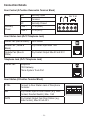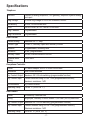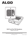
1
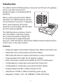
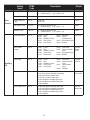
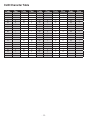
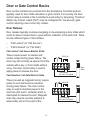
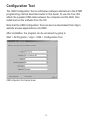
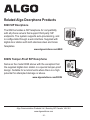
3226 Trunk Port FXO Doorphone
Installation and User Guide
Algo Communication Products Ltd., Burnaby, BC Canada V5J 5L2
www.algosolutions.com
-1-
Document #: 90-00040E
Important Safety Notice
The 3226 Trunk Port FXO Doorphone is designed and tested to comply with EN 60950-1:2006
safety requirements.
When the Doorphone Controller is connected to wiring that exits the building, there is potential
risk of lightning induced electrical surges or high voltages from fault conditions. To reduce risk,
outdoor wiring should be protected by Earth grounded conduit whenever possible.
If outdoor wiring will be connected to the Doorphone Controller then the power supply provided
with the Doorphone Controller must first be connected to a properly Earthed mains supply.
Under no circumstances can the Doorphone Controller be disconnected from Earth ground while
connected to outdoor wiring.
The 3226 Trunk Port FXO Doorphone is not intended to be directly connected to public telecom
networks.
Support
Algo is pleased to offer telephone or email support relating to installation issues, applications
assistance, or general product inquiries.
Algo Communication Products Ltd.
4500 Beedie Street
Burnaby, BC, Canada, V5J 5L2
[email protected] Tel: 604.454.3792
[email protected] Tel: 604.454.3790
Algo products are warranted against defect in workmanship for a period of 12 months after
installation not to exceed 18 months from date of manufacture. For warranty or non-warranty
repair support please contact your distributor or reseller. If necessary, contact Algo using the
support contacts listed above.
FCC Compliance
This equipment has been tested and found to comply with the limits for a Class B digital device, pursuant to part 15
of the FCC Rules. These limits are designed to provide reasonable protection against interference in a residential
installation. This equipment generates, uses, and can radiate radio frequency energy and, if not installed and used
in accordance with the instructions, may cause harmful interference to radio communications. However, there
is no guarantee that interference will not occur in a particular installation. If this equipment does cause harmful
interference to radio or television reception, which can be determined by turning the equipment off and on, the user
is encouraged to try to correct the interference by one or more of the following measures: 1) Reorient or relocate
the receiving antenna, 2) Increase the separation between the equipment and receiver, 3) Connect the equipment
into an outlet on a circuit different from that to which the receiver is connected, or 4) Consult the dealer or an
experienced radio/TV technician for help.
-2-
Table of Contents
Support . . . . . . . . . . . . . . . . . . . . . . . . . . . . . . . . . . . . . . . . . . . . . . . . . . . . . 2
FCC Compliance . . . . . . . . . . . . . . . . . . . . . . . . . . . . . . . . . . . . . . . . . . . . . 2
Important Safety Notice . . . . . . . . . . . . . . . . . . . . . . . . . . . . . . . . . . . . . . . . 2
Introduction . . . . . . . . . . . . . . . . . . . . . . . . . . . . . . . . . . . . . . . . . . . . . 4
Features . . . . . . . . . . . . . . . . . . . . . . . . . . . . . . . . . . . . . . . . . . . . . . . . . . . . 4
Quick Install & Test . . . . . . . . . . . . . . . . . . . . . . . . . . . . . . . . . . . . . . . 5
Application Basics . . . . . . . . . . . . . . . . . . . . . . . . . . . . . . . . . . . . . . . 6
Basic Wiring Setup . . . . . . . . . . . . . . . . . . . . . . . . . . . . . . . . . . . . . . . . . . . . 8
Programming & Configuration . . . . . . . . . . . . . . . . . . . . . . . . . . . . . . 9
Program Settings and Codes . . . . . . . . . . . . . . . . . . . . . . . . . . . . . . . . . . . . 9
CLID Character Table . . . . . . . . . . . . . . . . . . . . . . . . . . . . . . . . . . . . . . . . . 12
Door or Gate Control Basics . . . . . . . . . . . . . . . . . . . . . . . . . . . . . . 13
Door Release . . . . . . . . . . . . . . . . . . . . . . . . . . . . . . . . . . . . . . . . . . . . . . . 13
Power Supply . . . . . . . . . . . . . . . . . . . . . . . . . . . . . . . . . . . . . . . . . . . . . . . 14
Connections and Lights . . . . . . . . . . . . . . . . . . . . . . . . . . . . . . . . . . 15
Auxiliary Dry Contact Outputs . . . . . . . . . . . . . . . . . . . . . . . . . . . . . . . . . . 15
Auxiliary Dry Contact Inputs . . . . . . . . . . . . . . . . . . . . . . . . . . . . . . . . . . . . 15
Connection Details . . . . . . . . . . . . . . . . . . . . . . . . . . . . . . . . . . . . . . . . . . . 16
Specifications . . . . . . . . . . . . . . . . . . . . . . . . . . . . . . . . . . . . . . . . . . 17
Configuration Tool . . . . . . . . . . . . . . . . . . . . . . . . . . . . . . . . . . . . . . . 19
Related Algo Doorphone Products . . . . . . . . . . . . . . . . . . . . . . . . . 20
8028 SIP Doorphone . . . . . . . . . . . . . . . . . . . . . . . . . . . . . . . . . . . . . . . . . 20
8028V Tamper-Proof SIP Doorphone . . . . . . . . . . . . . . . . . . . . . . . . . . . . . 20
-3-
Introduction
The 3226 Trunk Port FXO Doorphone connects to an FXO port of a gateway
device, loop start trunk port of a
telephone system, or a traditional POTS
telephone
When a visitor presses the Door Station
call button, the 3226 Doorphone will ring
into the FXO port, trunk port, or telephone
which, when answered, will provide
hands-free communication with the visitor
and door opening capability.
The 3226 Doorphone includes a Control
Unit, Door Station, and Power Supply.
The Control Unit and Door Station can
be connected with a single twisted pair
wire up to 1,000 feet (300 m) with the Door Station located outdoors and the
Control Unit in a dry indoor location.
Features
•
Single pair digital communication between Door Station and Control Unit
•
Hands-free voice communication at the Door Station
•
DSP enhanced audio for superior performance in noisy environments
•
Programmable CLID (Caller ID) for telephone display
•
Door control relay contacts and available 24 Vdc 0.3 A strike power
•
Configurable dry contact input and output from Control Unit
•
Configurable dry contact input and output from Door Station
•
Programmable by DTMF or USB connection to PC
•
International 110/220 V, 50/60 Hz switching power supply
•
Regulatory: CSA/UL, FCC, CE, EN60950-1 2006 CB Scheme
-4-
Quick Install & Test
The 3226 Trunk Port FXO Doorphone is pre-configured for a typical
installation. Programming is only required to change default setting or for more
advanced applications.
1. Connect the power supply to the
Power Jack of the Doorphone
Controller and plug into an
available AC outlet.
2. Flush or surface-mount the
Digital Door Station at desired
location and connect a twisted
telephone wire pair between
the “CTRL” terminals of the
Door Station and the center pair
(red and green) of the supplied
Telephone Wiring Jack. Polarity
is not important.
3. Using the short six conductor
modular cable, connect the
Telephone Wiring Jack to
the Door Station Jack of the
Doorphone Controller.
4. Using the 6 foot (1.8 m) two-wire modular cable, connect your telephone,
FXO Gateway, or analog trunk port of a traditional phone system to the
Telephone Jack of the Doorphone Controller.
5. Press the call button of the Door Station. The phone will ring and the call
button will flash. A default CLID message of “Doorphone” is sent to the
telephone.
6. Answer to communicate with the Door Station. Press the DTMF digit 6 to
activate the door control relay for three seconds if applicable.
-5-
Application Basics
The 3226 architecture and digital link between the Door Station and Controller
provides flexible options using the auxiliary inputs and outputs. These are
some typical applications:
Cancel Ring When Door Opened
In a residential or warehouse installation it is not uncommon for the door to
be answered in person before the phone is answered. Either Door Station
or Control Unit inputs can be configured to cancel ring if the door is opened
before a call is answered. This requires a normally closed or normally open
contact to detect door open.
Trigger Door Bell from Door Station
When the Door Station call button is pressed, either (or both) the Door Station
or Control Unit dry contact output can be configured to activate a door bell or
auxiliary alerting system in addition to phone ring.
Trigger Door Station from External Button/Event
Either the Control Unit or Door Station can accept a dry contact closure to
activate the Doorphone as if the call button had been pressed. This could be
an external doorbell button, PIR detector, or some other system.
Cancel Door Open Relay once Door Opened
The door opening control can be set for activation (using the `Open Code’) up
to 30 seconds (set by the `Relay Time’ setting) to allow sufficient time for entry.
For security, the 3226 Doorphone can be configured to cancel Door Opening
once the door is opened to prevent “tailgating” by unauthorized personnel.
Unlock Door Indefinitely until Canceled
The door opening control can be set to unlock indefinitely (using the `Latch
Open Code’) until canceled (using the `Release Code’) that locks it again. This
allows an entrance to be used repeatedly for a period of time without requiring
multiple activations of the door control relay.
-6-
Anti-Door Tamper
A feature of the 3226 Doorphone is to ring the telephone(s) with a warning
alert in the event a door is ajar due to tampering (such as a door blocked open
after being legitimately released for a visitor).
In-Use and Ring
Either the Control Unit or Door Station can be configured to provide a dry
contact output during ring or in-use for channel selection (typically) of third
party video monitoring systems.
For more information on applications for the 3226 Trunk Port FXO Doorphone
please visit www.algosolutions.com/3226. The 3226 Doorphone firmware may
be modified by USB connection to a PC and Algo routinely accepts requests for
custom firmware for unique applications.
-7-
Basic Wiring Setup
3226 Doorphone Controller
24V 0.3A
24VDC 0.6A
USB Configuration
Port
Door Control Relay see Door Control
Section
Power Input 24 V 0.6 A
Door Station Jack
Telephone Jack. Connect
to FXO Gateway, analog
telephone, or phone
system trunk port
6-Wire Modular Cable
(Supplied)
Telephone Wiring
Jack (supplied)
BLACK
WHITE
BLUE
WH
Controller Dry
Contact Output
BL
B
K
Y
R
D
G
L
YELLOW
Z
RED
Controller Dry
Contact Input
GREEN
Twisted pair
typical 24 AWG
Max 1000 feet (300 m)
Station Dry
Contact Input
Door Station
Station Dry
Contact Output
CTRL
IN
-8-
OUT
Programming & Configuration
The 3226 Trunk Port FXO Doorphone may be programmed either by DTMF or
through software using the USB connection on the 3226 Controller.
To enter Program Mode via the DTMF interface, dial **00 followed by the four
digit password if configured (there is no password by default). The password
may be entered or changed via the USB interface.
After completing programming, return onhook to exit programming mode
before testing the new settings, as the audio path to the speaker is disabled
while in programming mode.
Program Settings and Codes
Setting
Name
Ring
Settings
Audio
Settings
DTMF
Code
Description
Default
Region
**11 nn
nn=00: North America
nn=01: Europe 1 Most Countries
nn=02: Europe 2 Austria & France
nn=03: Australia & NZ
(e.g. **1100 = North America)
00 North
America
Ring Cadence
**12 nn
nn=00: North America 2 sec on 4 sec off
nn=01: UK 1/2s on - 1/2s off - 1/2 s on
00 North
America
Ring Limit
**13 nn
nn=00: no ring
nn=01..09: limit to 1-9 rings
nn=10: no limit
5 rings
Cancel Ring if
Door Opened
**14 nn
nn=00: No
nn=01: Yes
00 No
CLID Number
**15 LL S…
LL = length of string (00 to 10)
S… = numeric string (e.g. **15041234 = “1234”)
None
CLID Name
**16 LL S…
LL = length of DTMF digit string (00 to 32). Note that 2
DTMF digits are required for each character in the Caller
ID name field, so a length value of 32 would be used to
enter a string of 16 characters.
S… = characters (2 digits each) per table below
(e.g. **160836474750 = “DOOR”)
"Doorphone"
Speaker Volume
**21 nn
nn=00..10: Speaker audio level in 3 dB steps
09
Mic Volume
**22 nn
nn=00..10: Microphone audio level in 3 dB steps
08
DSP
**23 nn
nn=00: Full Duplex with Noise Reduction
nn=01: Full Duplex without Noise Reduction
01
Microphone AGC
(Automatic Gain
Control)
**24 nn
nn=00: On
nn=01: Off
00
-9-
Setting
Name
Door
Control
DTMF
Code
Description
Default
Open Code
**31 LL S…
LL = length of string (00 to 04)
S… = numeric string
(e.g. **31016 = “6”)
Digit 6
Relay Time
**32 nn
nn=00: ¼ second
3 sec
Cancel with Door
Open
**33 nn
nn=00: No
nn=01: Yes
00 No
Latch Open Code
**34 LL S…
LL = length of string (00 to 04)
S… = numeric string
(e.g. **34017 = “7”)
None
Release Code
**35 LL S…
LL = length of string (00 to 04)
S… = numeric string
(e.g. **35018 = “8”)
None
Controller Output
**41 nn
nn=00:In-Use
nn=01:Ring
nn=02: Call Button Press
nn=03: Door Control
nn=04: Door Sensor
nn=05: Door Alarm
nn=06:Follow
Controller Input
nn=07: Follow Station Input
nn=08: Disabled
00 In-Use
Door Station
Output
**42 nn
nn=00:In-Use
nn=01:Ring
nn=02: Call Button Press
nn=03: Door Control
nn=04: Door Sensor
nn=05: Door Alarm
nn=06: Follow Controller
Input
nn=07: Follow Station Input
nn=08: Disabled
02 Call
Button
Press
Door Relay
**43 nn
nn=00:In-Use
nn=01:Ring
nn=02: Call Button Press
nn=03: Door Control
nn=04: Door Sensor
nn=05: Door Alarm
nn=06: Follow Controller
Input
nn=07: Follow Station
Input
nn=08:Disabled
03 Door
Control
Controller Input
**44 nn
nn=00: Door Sensor, Normally Open Input
nn=01: Door Sensor, Normally Closed Input
nn=02: Manual Door Release Input
nn=03: Door Control Lockout Input
nn=04: Call Button, Normally Open Input
nn=05: Call Button, Normally Closed Input
nn=06: Disabled
01 Door
Sensor NC
Door Station Input
**45 nn
nn=00: Door Sensor, Normally Open Input
nn=01: Door Sensor, Normally Closed Input
nn=02: Call Button, Normally Open Input
nn=03: Call Button, Normally Closed Input
nn=04: Disabled
02 Call
Button NO
Auxiliary
I/O
- 10 -
nn=01..30: 1-30 seconds
Setting
Name
Security
DTMF
Code
Description
30 sec
2 min
15 min
30 min
Max Door Open
**51 nn
nn=00:
nn=01:
nn=02:
nn=03:
Door Alarm
**52 nn
nn=00: Ring Phone every 6 seconds
nn=01: Ring Phone every 30 seconds
nn=02: Ring Phone every 5 min
nn=03: Ring Phone every 1 hour
nn=04: None
Restore Default
Settings
**55
Returns all settings to factory default values
- 11 -
nn=04: nn=05: nn=06: nn=07: Default
60 min
90 min
120 min
None
07 None
04 None
CLID Character Table
Code
00
01
02
03
04
05
06
07
08
09
10
11
12
13
14
15
16
17
18
19
Char
Space
!
"
#
$
%
&
'
(
)
*
+
'
.
/
0
1
2
3
Code
20
21
22
23
24
25
26
27
28
29
30
31
32
33
34
35
36
37
38
39
Char
4
5
6
7
8
9
:
;
<
=
>
?
@
A
B
C
D
E
F
G
Code
40
41
42
43
44
45
46
47
48
49
50
51
52
53
54
55
56
57
58
59
Char
- 12 -
H
I
J
K
L
M
N
O
P
Q
R
S
T
U
V
W
X
Y
Z
[
Code
60
61
62
63
64
65
66
67
68
69
70
71
72
73
74
75
76
77
78
79
Char
\
]
^
_
`
a
b
c
d
e
f
g
h
i
j
k
l
m
n
o
Code
80
81
82
83
84
85
86
87
88
89
90
91
92
93
94
Char
p
q
r
s
t
u
v
w
x
y
z
{
|
}
~
Door or Gate Control Basics
Door control contacts are provided from the Doorphone Controller and are
typically used for door strike activation or gate control. For security, the door
control relay is located in the Controller to avoid entry by tampering. The Door
Station dry contact output (OUT) may be configured for ‘low security’ gate
control requiring a low current dry contact.
Door Release
Door release typically involves energizing or de-energizing a door strike which
pivots to allow a locked door to open without retraction of the latch bolt. There
are two different types of door strikes:
•
“Fail Locked” (or “Fail Secure”)
•
“Fail Unlocked” (or “Fail Safe”)
Fail Locked / Fail Secure Electric Strike
These require power to release and
remain locked during power failure. The
door may still normally be opened from the
outside with a key, or from inside without
a key. The door control relay is used to
apply power to release the door.
Fail Unlocked / Fail Safe Electric Strike
These (as well as magnetic locks), require
power to lock and become unlocked
during power failure. The door control
relay is used to maintain power to the
door lock (NC and C contacts) which is
interrupted to release the door. Magnetic
locks may require override systems to
allow safety exit in the event of fire.
- 13 -
24V 0.3A
Door
Strike
“Fail Locked”
24 Vdc 0.2 A Typical
24V 0.3A
“Fail Unlocked”
24 Vdc 0.2 A Typical
Power Supply
The Doorphone Controller provides an auxiliary 24 V 0.3 A power supply which
is suitable for common types of door strikes. If more current or a different
voltage is required, then the customer must provide a matching power supply
for the electric strike or magnetic lock. Maximum switching capability of the
door control contacts is 1 A 30 V.
The Door Control relay may also be configured for alternate functionality
including In-Use, Ring, and Call Button Press.
- 14 -
Connections and Lights
Auxiliary Dry Contact Outputs
Both the Doorphone Controller and Door Station provide a dry contact output
for connection to auxiliary devices. Maximum switching capacity is 30 V 50
mA.
Default operations are as follows:
•
Doorphone Controller Output = In-Use (commonly used for camera control)
•
Door Station Output = Call Button Press (commonly used to activate a
secondary door bell)
Other options for Doorphone Controller output include Ring and Call Button
Press. Other options for Door Station output include In-Use and Door Control.
Auxiliary Dry Contact Inputs
Both the Doorphone Controller and Door Station can detect a dry contact
closure from auxiliary devices. A non-capacitive and non-inductive low voltage
and low current is used to detect contact closure.
Default operations are as follows:
•
Doorphone Controller input = Door Sensor Normally Closed (used to
detect door open)
•
Door Station input = Call Button Normally Open (used to detect external
doorbell switch)
Options for Doorphone Controller input include Door Sensor Normally Closed,
Door Sensor Normally Open, Manual Door Release, Door Control Lockout,
Call Button Normally Closed, and Call Button Normally Open.
Options for Door Station input include Door Sensor Normally Closed, Door
Sensor Normally Open, Call Button Normally Closed, and Call Button
Normally Open.
See “Programming & Configuration” on page 9 for more information on
options.
- 15 -
Connection Details
Door Control (5 Position Removable Terminal Block)
Relay
Auxiliary
Power
NO
Normally Open
C
Common
NC
Normally Closed
PWR -
0.3 A (GND)
PWR +
0.3 A (24 V)
24V 0.3A
Door Station Jack (RJ12 Telephone Jack)
Center Pair (Red & Green)
Door Station
Middle Pair (Yellow &
Black)
Dry Contact Input Max 1 kΩ
Outside Pair (Blue &
White)
Dry Contact Output Max 50 mA 30 V
Telephone Jack (RJ12 Telephone Jack)
Center Pair
Telephone
FXO Gateway
Phone System Trunk Port
Door Station (6 Position Terminal Block)
CTRL
Connect to Door Station Jack of Doorphone
Controller
SW
Dry Contact Input to Door Station (e.g. Door
Contact, Doorbell Switch); Max. 1 kΩ
DATA
Dry Contact Output from Door Station (e.g.
Gate Control); Max 50 mA 30 V
- 16 -
CTRL
IN
OUT
Specifications
Telephone
Interface
Connect to analog telephone, FXO gateway, telephone system analog
trunk port
Ring Voltage
65 Vrms ring voltage 20 or 25 Hz Sinewave, REN=2
Talk Battery
48 Vdc, 30 mA current limit
CLID
GR-30-CORE, BT 227, and ETS 300 659-1
Ring Cadence
Programmable
Ring Persistence
Programmable
Door Control
Contact Rating
Maximum 30 V 1 Amp
Contact Type
1 Form C, Normally Open and Normally Closed
Duration
Programmable, including latch
Activation
DTMF, programmable
Auxiliary Power
24 Vdc, current limited to 300 mA
Terminal Block
Wiring
12-26 AWG
Doorphone Controller
Power
AC Mains Adapter 95-230 V 50/60 Hz Included
Installation
Shelf or wall-mounted
Dry Contact Output Maximum 30 V 50 mA switching (programmable function)
Dry Contact Input
Contact detected using 24 Vdc 1 mA (programmable function);
Maximum resistance 1 kΩ
Environmental
Dry indoor location
Operating Temp.
0 to 40° C (32 to 104° F)
Door Station
Power
Provided by Controller link
Wiring
Single pair, normally 24 AWG twisted 1,000 Feet (300 m) Maximum
Dry Contact Output Maximum 30 V 50 mA switching (programmable function)
Dry Contact Input
Contact detected using 24 Vdc 1 mA (programmable function);
Maximum resistance 1 kΩ
Operating Temp.
-30 to 60° C (-22 to 140° F)
- 17 -
Weather
Resistance
CSA/UL NEMA 3R weather resistant for outdoor locations
Call Button
Backlit tactile silicon rubber
Installation
Flush or surface mounted using supplied plastic bezel; Fits two gang
electrical box
Faceplates
304 Stainless Steel, Brass; Optional Vandal-Proof (model 3203)
Programming
Method
DTMF or USB Port using configuration software
Power Requirement
Typical (idle)
1.5 Watts
Maximum*
10.5 Watts
* Audio Active, door contacts using 24 V 0.3 A auxiliary supply
Specifications are subject to change without notice. Some features
may only be available in specific firmware or hardware releases.
- 18 -
Configuration Tool
The USB Configuration Tool is a Windows software alternative to the DTMF
programming method described earlier in this Guide. To use the Tool, first
attach the supplied USB cable between the computer and the 3226, then
install and run the software from the CD.
Note that the USB Configuration Tool can also be downloaded from Algo’s
website at www.algosolutions.com/3226
After installation, the program can be accessed by going to
Start > All Programs > Algo > 3226 > Configuration Tool.
USB Configuration Tool Sample Screen
- 19 -
Related Algo Doorphone Products
8028 SIP Doorphone
The 8028 emulates a SIP telephone for compatibility
with all phone servers that support third-party SIP
endpoints. The system supports auto-provisioning, and
is configurable through a web interface. Supplied with
digital door station with both stainless steel and brass
faceplates.
www.algosolutions.com/8028
8028V Tamper-Proof SIP Doorphone
Same as the model 8028 above with the exception that
the supplied digital door station is a special tamper-proof
design. Suitable for environments where there is a high
potential for attempted damage or abuse.
www.algosolutions.com/8028V
Algo Communication Products Ltd., Burnaby, BC Canada V5J 5L2
www.algosolutions.com
- 20 -