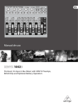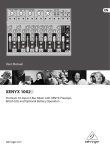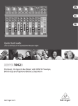
1
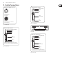
User Manual
1002
Premium 10-Input 2-Bus Mixer with XENYX Preamps, British EQs
and Optional Battery Operation
2
XENYX 1002B User Manual
Table of Contents
Thank you........................................................................ 2
Important Safety Instructions....................................... 3
Legal Disclaimer.............................................................. 3
Limited warranty............................................................. 3
1. Before you get started............................................... 4
1.1 Shipment................................................................................. 4
1.2 Online registration.............................................................. 4
1.3 Basic operation .................................................................... 4
2. Audio Connections..................................................... 5
3. Controls and Connectors .......................................... 6
3.1 Front panel............................................................................. 6
3.2 Rear panel.............................................................................. 7
4. Gain Setting................................................................ 7
4.1 Using external effects........................................................ 7
4.2 Creating a monitor mix .................................................... 8
4.3 Battery installation.............................................................. 8
5. Applications................................................................ 8
6. Specifications............................................................ 10
Thank you
Congratulations! With the PMP2000 you have acquired a state-of-the-art
14-channel power mixer that sets new standards. Right from the start, our goal
has been to design a revolutionary device that can be used for a great variety of
applications. And indeed, this overwhelming power mixer gives you plenty of
functionality and a broad range of connection and expansion options.
3
XENYX 1002B User Manual
Important Safety
Instructions
Terminals marked with this symbol carry
electrical current of sufficient magnitude
to constitute risk of electric shock.
Use only high-quality professional speaker cables with
¼" TS or twist-locking plugs pre-installed. All other
installation or modification should be performed only
by qualified personnel.
This symbol, wherever it appears,
alerts you to the presence of uninsulated
dangerous voltage inside the
enclosure - voltage that may be sufficient to constitute a
risk of shock.
This symbol, wherever it appears,
alerts you to important operating and
maintenance instructions in the
accompanying literature. Please read the manual.
Caution
To reduce the risk of electric shock, do not
remove the top cover (or the rear section).
No user serviceable parts inside. Refer servicing to
qualified personnel.
Caution
To reduce the risk of fire or electric shock,
do not expose this appliance to rain and
moisture. The apparatus shall not be exposed to dripping
or splashing liquids and no objects filled with liquids,
such as vases, shall be placed on the apparatus.
9. Do not defeat the safety purpose of the polarized
or grounding-type plug. A polarized plug has two blades
with one wider than the other. A grounding-type plug
has two blades and a third grounding prong. The wide
blade or the third prong are provided for your safety. If the
provided plug does not fit into your outlet, consult an
electrician for replacement of the obsolete outlet.
10. Protect the power cord from being walked on or
pinched particularly at plugs, convenience receptacles,
and the point where they exit from the apparatus.
11. Use only attachments/accessories specified by
the manufacturer.
12. Use only with the
cart, stand, tripod, bracket,
or table specified by the
manufacturer, or sold with
the apparatus. When a cart
is used, use caution when
moving the cart/apparatus
combination to avoid
injury from tip-over.
13. Unplug this apparatus during lightning storms or
when unused for long periods of time.
14. Refer all servicing to qualified service personnel.
Servicing is required when the apparatus has been
damaged in any way, such as power supply cord or plug
is damaged, liquid has been spilled or objects have fallen
into the apparatus, the apparatus has been exposed
to rain or moisture, does not operate normally, or has
been dropped.
15. The apparatus shall be connected to a MAINS socket
outlet with a protective earthing connection.
16. Where the MAINS plug or an appliance coupler is
used as the disconnect device, the disconnect device shall
remain readily operable.
Caution
These service instructions are for use
by qualified service personnel only.
To reduce the risk of electric shock do not perform any
servicing other than that contained in the operation
instructions. Repairs have to be performed by qualified
service personnel.
1. Read these instructions.
2. Keep these instructions.
3. Heed all warnings.
4. Follow all instructions.
5. Do not use this apparatus near water.
6. Clean only with dry cloth.
7. Do not block any ventilation openings. Install in
accordance with the manufacturer’s instructions.
8. Do not install near any heat sources such as
radiators, heat registers, stoves, or other apparatus
(including amplifiers) that produce heat.
LEGAL DISCLAIMER
TECHNICAL SPECIFICATIONS AND APPEARANCES
ARE SUBJECT TO CHANGE WITHOUT NOTICE AND
ACCURACY IS NOT GUARANTEED. BEHRINGER,
KLARK TEKNIK, MIDAS, BUGERA, AND TURBOSOUND
ARE PART OF THE MUSIC GROUP (MUSIC-GROUP.COM).
ALL TRADEMARKS ARE THE PROPERTY OF THEIR
RESPECTIVE OWNERS. MUSIC GROUP ACCEPTS NO
LIABILITY FOR ANY LOSS WHICH MAY BE SUFFERED
BY ANY PERSON WHO RELIES EITHER WHOLLY OR
IN PART UPON ANY DESCRIPTION, PHOTOGRAPH
OR STATEMENT CONTAINED HEREIN. COLORS AND
SPECIFICATIONS MAY VARY FROM ACTUAL PRODUCT.
MUSIC GROUP PRODUCTS ARE SOLD THROUGH
AUTHORIZED FULLFILLERS AND RESELLERS ONLY.
FULLFILLERS AND RESELLERS ARE NOT AGENTS OF
MUSIC GROUP AND HAVE ABSOLUTELY NO AUTHORITY
TO BIND MUSIC GROUP BY ANY EXPRESS OR IMPLIED
UNDERTAKING OR REPRESENTATION. THIS MANUAL
IS COPYRIGHTED. NO PART OF THIS MANUAL MAY
BE REPRODUCED OR TRANSMITTED IN ANY FORM
OR BY ANY MEANS, ELECTRONIC OR MECHANICAL,
INCLUDING PHOTOCOPYING AND RECORDING OF ANY
KIND, FOR ANY PURPOSE, WITHOUT THE EXPRESS
WRITTEN PERMISSION OF MUSIC GROUP IP LTD.
ALL RIGHTS RESERVED.
© 2013 MUSIC Group IP Ltd.
Trident Chambers, Wickhams Cay, P.O. Box 146,
Road Town, Tortola, British Virgin Islands
LIMITED WARRANTY
For the applicable warranty terms and conditions
and additional information regarding MUSIC Group’s
Limited Warranty, please see complete details online at
www.music-group.com/warranty.
4
XENYX 1002B User Manual
1. Before you get started
1.3 Basic operation
1.1 Shipment
The XENYX 1002B is easy to use. Simply follow these steps to achieve the best
possible sound:
Your XENYX 1002B was carefully packed at the factory and the packaging is
designed to protect the unit from rough handling. Nevertheless, we recommend
that you carefully examine the packaging and its contents for any signs of
physical damage which may have occurred during transit.
◊ If the unit is damaged, please do NOT return it to BEHRINGER,
but notify your dealer and the shipping company immediately.
Otherwise, claims for damage or replacement may not be granted.
◊ We recommend that you use a flight case, so as to give your power
mixer optimum protection during use or transport.
◊ Always use the original packing carton to prevent damage during
storage or transport.
◊ Make sure that children cannot play unsupervised with the device
or its packaging.
◊ Please ensure proper disposal of all packing materials.
1.2 Online registration
Please register your new BEHRINGER equipment right after your purchase
by visiting http://behringer.com and read the terms and conditions of our
warranty carefully.
Should your BEHRINGER product malfunction, it is our intention to have it
repaired as quickly as possible. To arrange for warranty service, please contact
the BEHRINGER retailer from whom the equipment was purchased. Should your
BEHRINGER dealer not be located in your vicinity, you may directly contact
one of our subsidiaries. Corresponding contact information is included in
the original equipment packaging (Global Contact Information/European
Contact Information). Should your country not be listed, please contact the
distributor nearest you. A list of distributors can be found in the support area
of our website (http://behringer.com).
Registering your purchase and equipment with us helps us process your repair
claims more quickly and efficiently.
Thank you for your cooperation!
1. Plug the included power cable into the back of the mixer. Plug the other end
of the cable into a mains outlet. DO NOT turn the mixer on yet.
2. Make all appropriate audio connections:
• Connect microphones to the MIC jacks using XLR cables
• Connect line-level sources to the LINE IN jacks using ¼" TS cables
• Connect stereo sources (keyboard, drum machine) to one of the
stereo LINE IN jacks using a pair of ¼" TS cables
• Connect a CD player to the 2 TRACK INPUT using ¼" or RCA cables
• See Applications chapter for more details and options
3. Connect a monitoring source or speaker system. You may connect
powered studio monitors, powered loudspeakers or a power amp to the
MAIN OUTPUT jacks. You may also connect a pair of headphones to the
PHONES jack. Leave powered speakers and/or power amps turned off until
the mixer has been powered on.
4. Turn all PAN/BAL and EQ knobs to their center (12 o’clock) position.
Set all other knobs and faders all the way down/off.
5. Once all connections have been made, you may turn the mixer on.
6. After the mixer is turned on, you may also turn the speakers or
power amp on.
7. Set the input gain level for each channel using the GAIN knob. While testing
the audio source, turn the GAIN knob as high as possible without allowing
the CLIP LED to light. See the Gain Setting section for details.
8. Raise the MAIN fader to 0. You may adjust it further as you begin
to set levels.
9. Adjust all channel volume faders until you achieve a balanced mix.
10. Make sure that the channel CLIP LEDs and MAIN CLIP LEDs do not
light frequently. If this happens, adjust the respective GAIN or MAIN
fader accordingly.
11. Congratulations! You have now set up a basic mix! The 1002B offers many
other cool features as well, so continue through the manual to make the
most out of this powerful little mixer.
5
XENYX 1002B User Manual
2. Audio Connections
Balanced use with XLR connectors
Unbalanced ¼" TS connector
strain relief clamp
sleeve
2 1
3
tip
input
1 = ground/shield
2 = hot (+ve)
3 = cold (-ve)
1
sleeve
(ground/shield)
2
3
tip
(signal)
output
For unbalanced use, pin 1 and pin 3
have to be bridged
Fig. 2.3: ¼" Unbalanced
Fig. 2.1: XLR Balanced
tip
Balanced ¼" TRS connector
tip
sleeve
shield
sleeve
strain relief clamp
sleeve
ring
tip
Fig. 2.4: RCA
Balanced ¼" TRS connector
strain relief clamp
sleeve
ground/shield
sleeve
ring
tip
ring
cold (-ve)
tip
hot (+ve)
sleeve
ground/shield
For connection of balanced and unbalanced plugs,
ring and sleeve have to be bridged at the stereo plug.
Fig. 2.2: ¼" Balanced
ring
cold (-ve)
tip
hot (+ve)
For connection of balanced and unbalanced plugs,
ring and sleeve have to be bridged at the stereo plug.
Fig. 2.5: Insert cable
6
XENYX 1002B User Manual
3. Controls and Connectors
3.1 Front panel
(3)
(7)
(4)
(5)
(16)
(15)
(21) (17)
(18)
(1)
(19)
(2)
(20)
(22)
(23)
(6)
(8)
(9)
(10)
(24)
(11)
(25)
(12)
(26)
(13)
(14)
(1) MIC – Plug a microphone into this input using an XLR cable.
(2) LINE IN – Plug a line-level source into this jack using a ¼" TS or TRS cable.
(3) INS(ERT) – Plug an external dynamic processor into this jack using a TRS to
dual TS cable. You may also use the INSERT jack as a pre-EQ/pre-fader send
by plugging in a ¼" TS cable part way to the first click.
(27)
(15) 2-TRACK OUTPUT – Connect to the inputs of recording device
using RCA cables.
(16) 2-TRACK INPUT – Connect to outputs of CD, tape or MP3 player using
RCA or ¼" cables.
(17) PHONES – Connect a pair of headphones with a ¼" TRS plug.
(4) STEREO LINE IN – Plug in a stereo source using two ¼" TS cables,
or a single line-level source using the left input jack only.
(18) MAIN OUTPUT – Connect to the inputs of a power amp or powered speakers
using ¼" TS cables.
(5) GAIN LINE – Adjusts STEREO LINE IN sensitivity, also known as
“gain setting.”
(19) FX SEND – Connect to the input of an external effects device using a
¼" TS cable.
(6) GAIN MIC – Adjusts MIC input sensitivity, also known as “gain setting.”
(20) MON SEND – Connect to the input of a powered monitor or monitor power
amp using a ¼" TS cable.
(7) CLIP – Lights when preamp begins to overload.
(8) PAN/BAL – Adjusts the left-to-right positioning of the channel in
the stereo field.
(9) HIGH – Adjusts frequencies above 10 kHz by ± 15 dB.
(10) MID – Adjusts frequencies peaking at 700 Hz by ± 15 dB.
(11) LOW – Adjusts frequencies below 50 Hz by ± 15 dB.
(12) MON – Adjusts the amount of signal sent to the MON SEND jack.
This signal is sent pre-fader.
(13) FX – Adjusts the amount of signal sent to the FX SEND jack.
This signal is sent post-fader.
(14) CHANNEL FADER – Adjusts the channel volume in the main mix.
(21) VU CLIP – Lights when the MAIN OUTPUT signal begins to overload.
(22) PHANTOM – Sends 23V of power to the XLR MIC inputs for use with
condenser microphones. When used with batteries, 18 V of power
is supplied.
(23) VU METER – Displays the MAIN OUTPUT signal level.
(24) MON SEND – Adjusts the output at the MON SEND jack.
(25) FX SEND – Adjusts the output at the FX SEND jack.
(26) PHONES – Adjusts the output at the PHONES jack.
(27) MAIN FADER – Adjusts the overall output of the mixer through the MAIN
OUTPUTS. It also affects the signal at the PHONES out and 2-TRACK OUTPUT.
7
XENYX 1002B User Manual
3.2 Rear panel
(28)
(29)
(28) AC POWER IN – Connect the mains power cable
into this input.
(29) POWER ON – Turns the mixer’s power on and off.
4. Gain Setting
It is very important to set each channel’s GAIN knob correctly in order to get
the maximum amount of signal headroom and least amount of noise possible.
Setting the GAIN too low could make that channel too quiet to mix properly,
while setting it too high will cause clipping and distortion. Stereo channels 3/4,
5/6 and 7/8 allow the MIC and LINE inputs to be used in parallel thanks to the
dedicated GAIN knobs for each input. Follow these instructions to set the gain for
each channel and situation:
• Plug the audio source into the channel input (XLR or ¼")
• Sing into the microphone or play the line-level source at the volume you
will ultimately use during recording or performance. If you set the gain
for a vocal mic by saying “check” into it, this gain setting will probably not
be as loud as the actual vocal performance. Setting the gain this way will
lead you to set the gain too high, which may cause the extra loud vocal
performance to overload and distort. Likewise, if checking a mic that will
record a saxophone, make sure the performer plays close to the mic while
setting the gain. For keyboards, do not change the output volume of the
keyboard after the mixer’s gain has been set
• Turn the GAIN knob clockwise until the red CLIP LED lights up. This means the
channel has begun to overload (too much signal is allowed in)
• Turn the GAIN knob counterclockwise a small amount, then sing or play
again. Ideally, the GAIN knob should be set as high as possible while allowing
the CLIP LED to only light occasionally, if at all
If you must use both the MIC and LINE inputs on channels 3/4, 5/6, or 7/8, you
can adjust the gain setting for each source individually thanks to the dedicated
GAIN knobs. The channel fader affects the level of both sources, so achieving a
good balance between the 2 inputs can be tricky.
• Set the gain for the MIC input using the GAIN MIC as described above
• Set the gain for the LINE input(s) using the GAIN LINE as described above
• Both GAIN knobs share the same CLIP LED, so when both sources are in use at
the same time, neither input should cause the LED to light. If this happens,
turn each GAIN knob down one at a time to determine which is overloading
• Raise the channel fader so that both sources are audible in the overall mix.
Ideally, they will already be balanced and not require further adjustment
• If one source is too quiet with the fader turned up, turn the louder
source’s GAIN knob down a bit, then raise the fader to the appropriate level.
DO NOT simply turn the quiet source’s GAIN knob up until it is loud enough,
as this will likely cause clipping and distortion
4.1 Using external effects
The 1002B lets you use external effects processors to add a touch of reverb,
delay, or other effects to various channels. Use the channel FX knobs, FX SEND
knob and FX SEND jack to send a portion of the signal from several channels to
an effects processor. You can insert the “wet” signal back into the mix through
one of the stereo channels. The FX signal from each channel is sent “post-fader,”
meaning that as you change the channel’s volume, you also change how much
of that channel’s signal is sent to the effects processor. This ensures that the
mix of wet and dry signal remains the same as you adjust the channel volume.
Follow these steps to incorporate external effects in your mix:
• Connect a ¼" TS cable from the FX SEND jack to the input of the
effects processor
• If you would like the effects to operate in stereo, connect ¼" cables from the
left and right outputs of the processor to one of the stereo input channels on
the 1002B
• For mono operation, most processors return a mono signal through the
left output. This mono signal should then be routed into the left input
on one of the mixer channels. If possible, use channel 9/10 since it only
allows line inputs
• Turn the FX SEND knob to the center (12 o’clock) position
• Turn the channel FX knob up for each source to which you would like to
apply effects. For example, you can add a lot of reverb to a vocal mic, while
only adding a small amount to a snare drum. This will just be a preliminary
setting as you will not be able to hear the effect yet. Keep the knobs around
the center position; you will fine-tune them shortly
• Adjust the input gain for the channel receiving the output from the
effects processor. (See the Gain Setting section for details.)
• Turn the channel fader up to 0 on the channel receiving the signal back from
the processor. DO NOT turn the FX knob on that channel up at all! Your sound
system will become haunted with screaming banshees
• You should now hear the selected effect on the channels that are sending
signal to the processor. Adjust the channel FX knobs to get the effect
mix just right
• NOTE: The processor will likely have its own VU meters to monitor the
incoming signal level. If the processor’s meter begins clipping, turn down the
FX SEND knob on the 1002B
See the Applications section for details.
8
XENYX 1002B User Manual
4.2 Creating a monitor mix
For live applications, audio engineers often send different mixes to the audience
and to the performing musicians. To allow this, the 1002B is equipped with a
dedicated monitor send bus. Each channel features a MON knob that sends a
“pre-fader” signal to the MON OUT jack, allowing the channel’s volume fader to
be adjusted without affecting the monitor mix. The signal can also be used as a
second effects send. Follow these steps to set up a basic monitor mix:
5. Applications
UL2000M
• Make sure the powered monitor speaker or power amp is turned off.
Connect a ¼" TS cable from the MON OUT jack to the powered speaker or
power amp
• Turn on the powered speaker or power amp, and then turn the volume up
about half way
• Turn the MON SEND knob to the center (12 o’clock) position. This setting may
need to be adjusted later depending on volume requirements
HPS5000
• As the musicians begin to play, turn each channel’s MON knob up slowly until
each source is audible in the monitor mix
• It may take some time to get a balanced mix that all the musicians are happy
with. If possible, avoid turning a channel’s MON knob much past the center
position. Do not point the monitor speakers directly at a microphone, as this
will likely cause feedback
See the Applications section for details.
As previously stated, the MON SEND jack can also be used as a second effects
send. This application requires a similar setup to the normal effects send,
but since the signal from each channel is sent pre-fader using the MON knob,
adjustments to the channel’s volume will affect the mix of wet and dry effect
signal. Therefore, if you alter a channel’s volume during the performance,
you must also adjust that channel’s MON knob.
XENYX1002B
UCA222
Fig. 5.1: Field Recording
• NOTE: When using the MON SEND for effects, if you neglect to change a
channel’s MON knob while turning that channel’s volume fader all the
way down, you will still hear the effected signal coming through the mix.
This problem happens because the signal routes “pre-fader,” but the normal
FX SEND bus will not experience this issue
4.3 Battery installation
The 1002B can be powered by three 9V batteries. This feature allows you,
for example, to capture a high-quality recording while sitting on the beach with
your laptop. You’re no longer tethered by an electrical outlet. You can still record
with condenser mics thanks to the 18V of phantom power supplied by two of the
batteries. Follow these steps to install the batteries:
DI100
• Open the battery compartment located on the underside of the mixer.
You will need to remove a small screw with a Phillips screwdriver
HPS5000
• Slide the compartment cover out. There are slots for three batteries inside
the compartment
• Insert the batteries so that the + and – poles are in the correct position
• Replace the cover and tighten the screw
The battery power will last approximately four hours using high-quality
alkaline batteries.
XENYX1002B
MP3 Player
Fig. 5.2: Live Small Combo
F1220A
B212D
9
XENYX 1002B User Manual
DSP2024P
HPS5000
B-1
B2031A
XENYX1002B
UCA222
Fig. 5.3: Computer Recording
DSP2024P
B-1
FCA202
HPS5000
XENYX1002B
DV Deck
Fig. 5.4: Video Editing
B2031A
10
XENYX 1002B User Manual
6. Specifications
Mono Inputs
CD/Tape In
Microphone inputs (XENYX Mic preamp)
Type
XLR connector, electronically balanced,
discrete input circuit
Type
RCA connector
Impedance
10 k Ohms
Max. input level
+22 dBu
Mic E.I.N.1 (20 Hz - 20 kHz)
@ 0 Ω source resistance
-134 dB 135.7 dB A-weighted
Equalizer
@ 50 Ω source resistance
-131 dB 133.3 dB A-weighted
LOW
50 Hz / ±15 dB
@ 150 Ω source resistance
-129 dB 130.5 dB A-weighted
MID
700 Hz / ±15 dB
Frequency response (-1 dB)
<10 Hz - 160 kHz (-1 dB)
HIGH
10 kHz / ±15 dB
Frequency response (-3 dB)
<10 Hz - 200 kHz (-3 dB)
Gain range
+14 dB to +60 dB
Max. input level
+12 dBu @ +10 dB GAIN
Impedance
2.6 k Ohms balanced
Signal-to-noise ratio
(0 dBu In @ +22 dB GAIN)
120 dB A-weighted
Distortion (THD + N)
0.005% / 0.004% A-weighted
Line Input
Type
¼" TRS jack, electronically balanced
Impedance
20 k Ohms balanced,
10 k Ohms unbalanced
Gain range
-10 dB to +40 dB
Max. input level
+22 dBu @ 0 dB GAIN
Channel Inserts
Type
¼" TRS jack, unbalanced
Max. input level
+22 dBu
MON/FX Send
Type
¼" mono jack, unbalanced
Impedance
120 Ohms
Max. output level
+22 dBu
Main Outputs
Type
¼" TRS jack, electronically balanced
Impedance
240 Ohms balanced,
120 Ohms unbalanced
Max. output level
+28 dBu
Frequency Response (Mic In → Main Out)
<10 Hz - 90 kHz (-1 dB)
+0 dB / -1 dB
<10 Hz - 160 kHz (-3 dB)
+0 dB / -3 dB
Phones Output
Type
¼" TRS jack, unbalanced
Max. output level
+19 dBu / 150 Ohms (+25 dBm)
Stereo Inputs
Type
2 x ¼" TRS jack, balanced
Impedance
10 k Ohms unbalanced
20 k Ohms balanced,
Gain range
-20 dB to +20 dB
Max. input level
+22 dBu @ 0 dB GAIN
CD/Tape Out
Type
RCA connector
Impedance
1 k Ohms
Max. output level
+22 dBu
11
XENYX 1002B User Manual
Main Mix System Data (Noise)3
Main mix @ -∞,
channel fader @ -∞
-100 dB / -102.5 dB A weighted
Main mix @ 0 dB,
channel fader @ -∞
-82 dB / -85 dB A weighted
Main mix @ 0 dB,
channel fader @ 0 dB
-72 dB / -75 dB A weighted
Power Supply
Power consumption
50 W
Fuse (100-120 V~, 50/60 Hz)
T 2,0 A H 250 V
Fuse (220-230 V~, 50/60 Hz)
T 2,0 A H 250 V
Mains Voltage
USA/Canada
120 V~, 60 Hz, Power Supply MXUL4
U.K./Australia
240 V~, 50 Hz, Power Supply MXUK4
China/Korea
220 V~, 50 Hz, Power Supply MXCHN4
Europe
230 V~, 50 Hz, Power Supply MXEU4
Japan
100 V~, 50-60 Hz, Power Supply MXJP4
Phantom Power
With battery power
+18 V
With AC adaptor
+23 V
Battery
Battery life
4 hours w/ high quality Alkaline battery
Physical/Weight
Dimensions (H x W x D)
1 9/16" / 2 7/8 x 11 3/4 x 8 1/2"
40 mm / 73 x 298 x 216 mm
Weight 5.5 lbs / 2.5 kg (PSU not included)
We Hear You