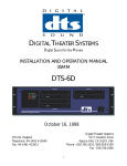
1
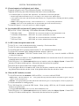
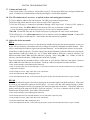
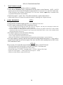
DIGITAL THEATER SYSTEMS, INC.
Digital Sound For Movies
DTS-6 /-6D System Testing
And
Troubleshooting
August 1999
DTS SA, UK
Telephone: 44 (0) 118 934 9199
Fax: 44 (0) 118 934 9198
Digital Theater Systems, Inc.
5171 Clareton Drive
Agoura Hills, CA 91301 USA
Telephone (818) 706-3525
Fax (818) 706-1868
Email [email protected]
TABLE OF CONTENTS
Page
DTS System Test ………………………………………………………………..… 3 – 5
70mm Failsafe Test ……………………………………………………………….. 6
DTS Test Discs (history) ………………………………………………………….. 7
Empirical Test Disc (menu) ……………………………………………………….. 8
DTS System Troubleshooting Guide ……………………………………………… 9 – 16
DTS-6/6D Player Troubleshooting Guide ………………………………………… 17 – 18
Replacing TEAC CD-ROM Drives …………………………………………………...19 – 25
TEAC
Jumper (address) Drawing ……………………………………………………………….21
DTS-6 (2-drive) Top View Drawing ……………………………………………………………22
DTS-6D (3-drive) Top View Drawing …………………………………………………………23
U14 (TCR) & AQRM Drawing …………………………………………………………………. 24
SCSI & ROM
Board Drawing …………………………………………………………………….25
Blinking Timecode Reader LED (Troubleshooting Guide) ………………………. 26 – 28
Timecode Signal Drawing ………………………………………………………………………28
DTS-6 35mm / 70mm System Parts List ……………………………………….. 29
DTS-6D 35mm / 70mm System Parts List ……………………………………… 30
Replacement Parts List (DTS-6/ -6D) ………………………………………………. 31
How To Contact DTS …………………………………………………………… 32
Main Office
Digital Theater Systems * 5171 Clareton Drive * Agoura Hills, CA 91301 USA
Telephone (818) 706-3525 * Fax (818) 706-1868
Thank you for choosing DTS !
2
DTS-6/6D System Test
Tools Required
** RTA (real time analyzer) and pink noise card. Necessary to adjust EQ in “B” chain.
** SPL meter
Projector Speed Disc (special order from DTS)
DTS Technician’s Kit:
• 6-Track SETUP Disc, Rev. DS1
Used to adjust DTS-6D levels, check automatic default switching, and verify operation of drives & player.
• “Buzz and Bill Show” Disc (dated Feb. 1, 1999)
• DTS Demo Film, 35mm
Used with the DTS Demo Film to test the DTS system.
Used with the “Buzz and Bill Show” disc.
• DTS Empirical Test Disc (dated June 7, 1997)
Used to test the theater’s sound system
NOTE
** These items are not supplied by nor are available from DTS.
All tests should be preformed with no audience in the theater.
Test Procedure
1.
Before testing the DTS system, check and adjust the theater cinema processor’s B-chain. This must
be checked first. All level adjustments should be made with master fader set to “7”.
Remember, any changes to the B-chain will effect the DTS system.
2.
Be sure the rear panel AC voltage switch is properly set for your main AC supply rating. Power on
the DTS player and remove any discs.
3.
Sync. Thread up the DTS demo film and use its special leader to calculate the offset. Verify this
matches the OFFSET setting (delay) on the DTS player.
4.
Insert the Setup Disc into the DTS player. You may use either the RevC or DS1 Setup Disc. The
player should easily accept the DTS disc. Once the DTS player boots up, it should automatically
switch the cinema processor to the correct format and tone/pink noise should be heard in the theater.
5.
Set DTS levels. Open the screen curtains and ensure master fader is set to “7”. Take SPL meter into
the theater and stand off-center in the rear third of the theater. SPL readings should be measured
unweighted, or C weighted - slow. Verify all output levels are as noted below. Do NOT point the
sound pressure level meter out of the porthole window, this will not give you correct SPL readings.
• Left channel PINK noise
• Left surround PINK noise high passed at 80Hz
• Center channel PINK noise
• Right surround PINK noise high passed at 80Hz
• Right channel PINK noise
• Sub bass channel PINK noise low passed w\DTS filter
3
SPL
85dB
82dB
85dB
82dB
85dB
91dB
DTS SYSTEM TEST
6.
Index Switch. A small black momentary push button switch located below the TIMECODE HEAD
switches (behind the plate and under the LEDs). It is commonly called the “index switch”.
This button can be used to increment to the next track being played. This feature works on the DTS
6-TRACK SET UP discs RevC and Rev.DS1 only. On shows of serial number 1009 and higher, the
momentary button also bypasses the DTS processor to allow checking of the optical bypass function.
OFFSET
NOTE: All DTS-6D units have this switch, but all DTS-6 units under serial number 1000 do not.
The index switch can be added by installing DTS kit D475.
7.
Mono Surround. For those theaters with mono surround only, wait for either the left -or- the right
surround PINK noise when adjusting the MONO SURR trimpot for 82dB SPL.
8.
Subwoofer. The DTS subwoofer output level ranges from 20Hz to 80Hz.. Observation of your
subwoofer’s specifications must be taken to avoid damage to the speaker. If a subwoofer is
driven below its cutoff frequency, its driver may become unloaded. When unloaded, the voice coil
can travel outside of the magnet’s gap, thus overheating or causing mechanical damage to the
speaker. A high pass filter should be installed on those speakers with high cutoff frequencies.
Contact the speaker’s manufacturer for details.
DTS Subwoofer in the Surrounds?
The DTS subwoofer signal is derived by filtering out the surround signals from 80Hz and below.
That signal is put on its own “subwoofer” output on the DTS player. You may verify this while
tuning (EQ-ing) a theater. Insert the DTS Setup disc into the player and play the subwoofer pink
noise off the disc. Turn off the subwoofer speaker and look at the pattern on the RTA (real time
analyzer). On a DTS-6D, you’ll see a dramatic roll-off at 80Hz (on a DTS-6, its less of a roll-off). It is
normal to hear DTS subwoofer, above 80Hz, in the surrounds. For that reason, you may choose to
turn off the surrounds when adjusting the DTS subwoofer SPL.
9.
Remove the Setup Disc and insert the “Buzz and Bill Show” Disc. Once threaded and the DTS
“SYSTEM” light flashes, start running the DTS demo film.
10.
Verify the DTS system automatically switches the cinema processor to the correct sound format
and the DTS digital sound track is playing:
* The DIGITAL, CD-ROM, and TIMECODE lights on the player should be on steady
* The SYSTEM light on the player should be flashing
* The CD-ROM drive light (that is playing the disc) should be flashing sporadically
* The green light on the reader should be glowing steadily and not flashing
11.
Verify the digital sound track is playing by turning off the (sound) exciter lamp. The sound track
should still be heard. Once verified, turn the exciter lamp back on.
12.
Fail-safe. Block the timecode and verify the cinema processor automatically switches to a stereo
optical (sound) format. There should not be a significant level difference between optical and digital
sound (in a quite scene). If there is, recheck the “B” chain and the DTS player level settings.
4
DTS SYSTEM TEST
13.
Unblock the timecode. Once the cinema processor automatically returns to a digital format, go into
the theater and listen to the sound track. Verify good sound quality and lip sync. Also verify no
extraneous noise during the quiet scenes.
14.
DTS-6D Programmed Default. Use the SET-UP DS1 disc to test all the default functions on the
player. Load the SET-UP DS1 disc in the DTS-6D and stand next to the unit when performing this test.
To start, allow the right channel’s pink noise to play in the theater. Eject the disc by pushing the
open/close button on the drive. The cinema processor should automatically pulse to the 04 (A-type)
format. Repeat procedure for the remaining formats as listed:
Pink noise channel
Default Format
Left
Left & Right Surround
Center
Right
A-type (04)
Non-sync
SR (05)
Mono (01)
DTS-6 Programmed Default. Use either the RevC or DS1 Setup disc to set levels. To check
default, eject the disc and verify the cinema processor automatically pulses to an optical sound
format. The DTS-6 system can default to either “A” type (04) or “SR” (05). This is determined by
jumper settings on external DTS logic boards.
D422 board, INDEX SWITCH, (push-button) behind the front panel plate
5
DTS 70mm Fail-safe Test
NOTE: If using one DTS-6D unit, there is no fail-safe or fall-back available on this type of system. If
using two DTS-6D units, verify connections to the fail-safe board. See installation manual.
There are no magnetic sound tracks on DTS 70mm prints.
Tools Required
DTS 70mm offset measurement film
DTS 70mm formatted film and two sets of discs that match the film.
DTS Setup Disc, DS1
Test Procedure
1.
Use the DS1 Setup Disc to verify that both players have the same SPL output. Adjust level pots, if
necessary.
2.
Offset.
• If this is already setup for DTS 35mm, be sure to write down that offset setting before proceeding.
• Two DTS players and one 70mm reader: Use the DTS 70mm offset measurement film to
calculate the delay. Verify both players have their OFFSET switches adjusted to this number.
• Two DTS players and two 70mm readers: First verify which reader goes with which player. The
easiest way to do that is to power on each player one at a time and see which reader powers. Label
each player and reader pair.
• Use the DTS 70mm offset measurement film to calculate the delay on the first reader. Set the
matching player OFFSET switches to this number.
• Measure the second reader and set the second player.
• Label the player to the OFFSET setting for 70mm and 35mm. Best place to put that is behind the
front plate.
3.
Thread the DTS 70mm test film through the projector and reader(s).
4
Load the matching CD-ROM discs into the DTS players: One disc in the “main” unit and the second
disc in the “backup” unit.
5.
Start the projector. The cinema processor should automatically switch to a digital sound format and
both players should be playing in digital -- their SYSTEM lights should be blinking and their DIGITAL
lights should be on solid. Turn up the booth monitor so that sound is heard.
6.
Failsafe check. While playing in DTS, eject the disc(s) from the main player. The backup player
should immediately take over. No interruption or change in sound should be heard.
7.
Load the disc(s) back into the main player. Once it starts playing in digital it will take over the
backup unit. No interruption or change in sound should be heard once the main unit plays in digital.
8.
Get another person to assist you and repeat steps 5 & 6 while you are listening in the theater.
9.
If the two players do not sound the same, go through the setup procedure for each unit and repeat
70mm fail-safe test again.
10.
If using two projectors, repeat the test for the second projector.
‘
6
DTS TEST DISCS
Below is a list of all the test discs released by DTS. Some of these test discs are obsolete and should no
longer be used. In most cases, the discs are obsolete due to software changes that made them incompatible
with current DTS players. Normally, when a test disc is obsolete, DTS will send free upgraded discs to
people who have purchased DTS Technician’s Kits. Sometimes, we miss a few people. Anyone who was
missed is still entitled to a free upgraded disc. They should contact DTS Customer Service (818) 706-3525).
CURRENT
OBSOLETE
TITLE
NOTES
•
Stereo Setup
Stereo DTS players obsolete. Do not use.
•
Stereo Demo
Stereo DTS players obsolete. Do not use.
•
6-Track Setup, RevC
May be used to set SPL levels, will not work
in DTS-6D Drive C. Do not use.
•
6-Track Setup, RevD
Has a bug. Do not use.
6-Track Setup, DS1
Used to checks DTS-6D defaults.
•
6-Track Demo, D-1
Original demo disc, old software. Do not
use.
•
Buzz and Bill Show
6-track demo remix, no date, has a bug
not use.
•
Buzz and Bill Show
June 27, 1997, do not use.
Buzz and Bill Show
February 1, 1999. Has SMPTE RP200.
Empirical Test
No date. Will not work in DTS units with
Adaptec/Acqutek SCSI. Do not use.
•
Empirical Test
June 7, 1997
•
Projector Speed Test
Special order only.
Strobe Test
June 17, 1997, normally not distributed. Has
a software bug. Do not use.
•
•
•
•
•
* Stand Alone Trailer Disc
Do
Has old software that may cause current
players to malfunction. Do not use.
* DTS Trailer Discs
Use only most current trailer discs. Any disc specially made for a particular cinema chain, must contain the
current software file.
7
DTS EMPIRICAL TEST DISC
Tests #1 through #35 will play automatically. For a specific test, wait for the announcement, then select the desired test number on
the TIMECODE HEAD OFFSET rotary switches (located behind the player's front panel access cover). Be sure to write down the
current offset setting before your selection is made and restore the setting for proper DTS movie playback. NOTE: *Some of
these test signals may cause serious damage to sound systems that are not properly designed to reproduce the extended
dynamic range of a digitally-based sound storage system.
1
*2
3
4
5
6
7
8
9
10
11
12
13
14
15
16
17
18
19
20
21
22
23
24
*25
26
27
*28
29
*30
*31
*32
*33
*34
*35
36
37
38
39
40
41
42
43
44
45
46
47
48
49
50
Empirical test section announcement
Power handling test
Left level, set channel ID, pink noise @ 0dB alternating with low level multi-tone
Left surround level set
Center level set
Right surround level set
Right level set
Male voice for speaker comparison
Female voice for speaker comparison
Music for speaker comparison
Dialog, front speaker balance
Pink noise, surround speaker balance
Music, front speaker balance
Digital silence
Left channel ID, -10dB sweep, 0dB sweep
Left surround channel ID, -10dB sweep, 0dB sweep
Center channel ID, -10dB sweep, 0dB sweep
Right surround channel ID, -10dB sweep, 0dB sweep
Right channel ID, -10dB sweep, 0dB sweep
Room acoustics test: left surround, right surround, center
Left level sweep 400 Hz, -5dB to +5dB
Left surround sweep 400 Hz, -5dB to +5dB
Center level sweep 400 Hz, -5dB to +5dB
Right surround sweep 400 Hz, -5dB to +5dB
Right level sweep 400 Hz, -10dB to +20dB
Left level sweep 400 Hz, -10dB to +10dB
Left surround level sweep 400 Hz, -10dB to +10dB
Center level sweep 400 Hz, -10dB to +20dB
Right surround level sweep 400 Hz, -10dB to +10dB
Right level sweep 400 Hz, -10dB to +20dB
Left explosion @ +10dB, +20dB
Left surround explosion @ +10dB, +20dB
Center explosion @ +10dB, +20dB
Right surround @ +10dB, +20dB
Right explosion @ +10dB, +20dB
Must dial in remaining programs listed below
1KHz @ reference level, all channels (250mV RMS)
Left pink noise @ reference level (85dB SPL)
Left surround pink noise @ reference level (82 dB SPL)
Center pink noise @ reference level (85dB SPL)
Right surround pink noise @ reference level (82dB SPL)
Right pink noise @ reference level (85dB SPL)
Sub bass pink noise @ reference level (85dB SPL)
Left 1/3 octave pink sweep 25 Hz - 2 KHz, 1 second pause, sweep 2 KHz - 20 KHz
Left surround 1/3 octave pink sweep 125 Hz - 2 KHz, 1 second pause, sweep 2 KHz - 20 KHz
Center 1/3 octave pink sweep 25 Hz - 2 KHz, 1 second pause, sweep 2 KHz - 20 KHz
Right surround 1/3 octave pink sweep 125 Hz - 2 KHz, 1 second pause, sweep 2 KHz - 20 KHz
Right 1/3 octave pink sweep 25 Hz - 2 KHz, 1 second pause, sweep 2 KHz - 20 KHz
Sub Bass sweep 20 Hz - 80 Hz
5 channel pop test, channel number ID by number of pops
4 seconds pink noise: left, center, right, left surround, right surround
8
DTS SYSTEM TROUBLESHOOTING
1. Movie not playing in DTS digital sound, CP (cinema processor) won’t switch to DTS format.
Is the SYSTEM light blinking on the DTS player?
NO System is not ready to play. Ensure movie disc(s) are in the DTS player. They should match the movie
playing. Turn off DTS player power switch, wait 3 seconds, switch back on. If SYSTEM light doesn’t blink,
repeat test using another set of movie discs or use a DTS test disc.
• If the SYSTEM light doesn’t blink, try the DTS
Setup Disc. If that won’t work, check the power.
* Verify the rear panel power switch is correctly set. Are the AUTOMATION and ANALOG cables swapped?
* Is the power supply’s fan turning? If not rotating, turn off power switch and remove player’s top cover.
• Verify the spade lugs on the power switch are securely attached.
• Use a multimeter to verify the power switch is switching correctly. Can be checked at AUX AC socket in rear panel.
• If the power switch is correctly wired and the switch tests OK, check power on the motherboard.
• On the motherboard, if the voltage from the power supply is not correct, replace the supply.
* If the voltage input to the motherboard is good, turn off power and push down all the internal boards onto
their connectors. Be sure all cables are securely connected and their PIN 1 is correctly oriented. Try test
again by inserting any DTS disc into player. If the SYSTEM light starts to blink, reinstall.
* If the power supply is good but the player won’t boot up, replace player.
YES
* Is the player’s TIMECODE light on solid?
• If not on, is the film threaded through the DTS reader?
• Is the reader’s red LED (inside the lens) on?
Is DTS timecode on the print?
• If not on, the reader isn’t getting 5v DC from the player. Verify the cable connection from player to reader.
Check cable’s pin-to-pin continuity. Check for shorts or opens in cable. Check that the fuses inside the DTS
player are not blown (NOTE: DTS-6D use self resetting circuit breakers).
• Is the reader’s green LED on?
• If not on, attach the grounding jumper on the reader’s timecode cable to the projector. Easiest place to do that is
attach to the screw that secures the timecode cable to the reader head. The reader’s housing must be electrically
connected to the projector housing. Verify with an ohm meter. This is needed for projectors that are not
properly grounded.
• If grounding the projector doesn’t help, replace reader.
• If the TIMECODE light is blinking, see number 2, next page, follow steps in “Is reader’s green LED blinking?”
• If the reader’s green LED is very dim, replace the reader.
* Is the DTS player’s DIGITAL light on?
• If not on, verify only theatrical discs are in the player. Use only one movie title and trailer disc at a time.
• If not on, verify the movie discs match the movie playing. Turn DTS player power off, wait 3 seconds, and power
on the DTS player. This must be done when changing movie/trailer discs.
• If not on, is a Dolby SR-D (DA10 or DA20) connected to the CP as well as DTS?
• If yes, turn the DA10/20 off, it interferes with the format switching.
• If not on, test the speed of the projector by using the DTS Projector Speed Test Disc.
with disc.
(#1 continued next page)
9
Follow directions included
SYSTEM TROUBLESHOOTING
1. (continued). Movie not playing in DTS digital sound, CP (cinema processor) won’t switch to DTS format.
* Is CP in the correct sound format? In most cases, DTS will automatically pulse the CP.
• If re-starting after film break, some automation systems may switch the CP out of the digital format.
•
If
this occurs, it will be necessary to reselect the digital format manually.
Is the BS22 cable (DTS-6) or automation cable (DTS-6D) connected to CP logic? Verify PIN 1.
• Use DTS Setup Disc to verify the DTS player automatically switches into digital. Some CP models will be pulsed
into a digital format and other CP models will have their analog outputs switched out by
board.
CP
Format for DTS
CP50
Select “04” or “05” for backup, DTS will switch over Note:
CP55
DTS pulses CP to “Aux” format
CP65
DTS pulses CP to Format 10 or “Dolby Digital” format.
CP100
Select “04” or “05” for backup, DTS will switch over Note:
CP200
Select “04” or “05” for backup, DTS will switch over Note:
CP500
DTS pulses CP to “Format 11”
UltraStereo
DTS pulses CP to “Digital” or “digital/ext” formats
relays on DTS interface
BS22 not used
BS22 not used
BS22 not used
2. DTS digital movie defaulting to optical (analog) and not staying in digital.
The sound should automatically default to optical when the DTS player does not see timecode for four seconds.
Verify the green LED on the DTS reader head is glowing brightly and steadily while the film is running. The DTS
player will also default to optical if the timecode is sporadic or the DTS CD-ROM discs cannot be read.
* Defaulting during the same place in the movie? If so, ask distributor for replacement reel.
• No cues should be placed within timecode. The DTS player does not recognize them.
* Defaulting sporadically or throughout the film:
Is reader’s green LED blinking? It should be solid bright, very
occasional blink is OK.
• If only one reel blinks, ask distributor for replacement reel.
• If the reader blinks every other reel and is in a platter house, turn off the DTS player. Take the unit out
of the rack and open the lid. Look inside, at the timecode card (one with LEDs). Verify the jumper is
positioned horizontally across the top row of W1. The jumper should not be installed vertically (vertical
placement is for two projectors only).
• Frequent blinking on all reels is usually a reader or tension problem.
• If the TIMECODE light on the DTS player or reader is blinking, gently squeeze the film between two fingers as it enters
the reader and pull back. If the blinking stops and maintains a steady glow, this indicates more tension is needed.
Tension is added by repositioning the auxiliary flanged roller on the reader so that it has maximum contact with the
film, or add a cleaning roller to system.
• Gently squeeze the film between two fingers as it exits the reader. If the blinking stops, check projector for worn
gears or belts. An oscilloscope should be used to observe signal. See “Checking Timecode With An Oscilloscope”.
• Christie platters: This platter has a spring in the center cluster (center roller) which should be in good condition,
clean and well lubricated. Do not remove it. If removed, it will cause film bounce, which causes the DTS reader to
not see good timecode.
• If the TIMECODE light is blinking, see “Blinking Timecode Reader LED” notice in this book.
• Attach the grounding jumper on the reader’s timecode cable to the projector.
Attach the jumper to the
screw that secures the timecode cable to the reader head. The reader’s housing must be electrically
connected to the projector housing. Verify with an ohmmeter. This is needed for projector chassis that are
not properly earth grounded.
• If grounding the projector doesn’t help, replace reader with Rev.F or rework reader’s ground plane per Section VI.
• Make no adjustments to readers with a serial number, unless directed by a DTS engineer.
•
If the reader does
not have a serial number, gently rotate the screw in the largest roller to see if the light stabilizes. If it
doesn’t, replace reader.
If the reader’s green LED is very dim, replace the reader.
(#2 continued next page)
10
SYSTEM TROUBLESHOOTING
2. (continued) DTS digital movie defaulting to optical (analog) and not staying in digital.
• If
the reader’s green LED is solid and the DTS still defaults, look at the lights on CD-ROM drives
themselves. They should blink sporadically when their disc is being read. If the drive light is on solid, this
means the drive cannot read the disc. Try another disc.
• If the problem goes away, the original disc may be bad. Inspect disc and/or replace it.
• If disc needs cleaning, use a clean dry cloth to wipe off disc, wipe from middle straight out. Carefully place disc in
caddy and close the door until it snaps in place. Load caddy into drive and try playing it.
• If disc is deeply scratched or marked, it’s not useable. Replace disc.
• If disc won’t play, replace it.
• If using a caddy, eject it from the drive and verify the caddy’s silver door opens easily. Carefully open the caddy
door and verify the disc is OK. Be sure no paper is in the caddy. Caddy should close completely.
• Replace any bad caddy.
• If using a caddy-less drive, eject the disc from the drive and inspect it. Clean the disc if necessary. If deeply
scratched or marked, it’s not usable. Replace disc.
• If the problem continues, the drive is bad. If the light on the drive comes on, it means it cannot read the disc.
Cleaning the drive might help. Use a CD-ROM Laser Lens Cleaner (disc). This will clean off the laser’s window
(lens) to the disc. If cleaning the drive doesn’t help, replace it.
• Be sure the theater is not using an old trailer disc. The DTS.EXE file on all discs should be current. Current EXE
files slow down the speed of drives making the disc easier to read.
* Last resort is to force the CP to play in optical sound format and replace the DTS player.
3. Channels don’t sound balanced.
* If same in optical, not a DTS player problem.
* If only in DTS, check DTS SPL settings. Set SPL meter to “C” and “slow”.
Use DTS Setup Disc to test channel output in theater: Screen channels should be 85dB SPL, subwoofer should be 91dB
SPL, and the surround channels should be 82dB SPL. The B-chain must always be adjusted first, then adjust DTS levels
inside the theater.
4. Channel(s) are mixed together or coming out of the wrong speakers.
Force the DTS player to play in optical sound format by selecting either 04 or 05 and powering off DTS player.
* If channel(s) still wrong, not a DTS player problem. Are all amps powered on? Are they correctly wired?
* If the problem goes away, then play movie in optical until there is time to troubleshoot.
• Was DTS player moved?
Is DTS JM21 (DTS-6) or ANALOG OUT cable (DTS-6D) plugged correctly into CP? Are
cables pushed down on all connectors? Inspect DTS audio board and wiring.
• Use DTS Setup Disc to test each channel’s output from DTS player.
Listen in theater to verify pink noise is coming
out of the correct speakers. Use multimeter to track signal path.
• Verify signal outputs from DTS when disconnected from CP. Inspect DTS audio board and wiring.
• Reconnect DTS and verify channel inputs to CP and speaker amplifiers.
• Verify ground connection is good and that the correct ground is being used.
* If
•
•
DTS surrounds playing mono and stereo is needed, verify DTS output is properly wired to CP.
DTS-6, verify the 3 programming jumpers/switches inside unit (transformer board) are set to STEREO (all up). All
switches down is for MONO surround.
DTS-6D, verify DTS audio breakout board’s jumpers are correctly set and board is correctly connected to CP.
5. Hear thumping noise when DTS print playing in optical.
Sound head picking up timecode track. Sound head needs lateral adjustment until thumping stops. Thread up
buzz track and make adjustments. A complete “A” chain alignment is recommended.
11
SYSTEM TROUBLESHOOTING
6. Sound not in sync with picture.
* Turn
off the DTS player until the audience leaves. Get the DTS numbered leader. Thread it through DTS
reader & projector. Put “00” at reader’s lens and find number at sound head. This is your OFFSET number.
• If DTS leader is not available, do the frame count method: Count the number of frames from the DTS reader lens to the
picture aperture. Multiply the result by 1.25 and subtract one. The outcome is the offset number. Example: 27 frames
X 1.25 = 33.75 - 1 = 32.75. Round this number off the next whole number, so 33 would be your offset number.
• Verify the result is the same number adjusted on the DTS player’s OFFSET switches.
Change if necessary.
* Sound sync is verified to picture by watching mouth movements in tight shot dialogue scenes.
If the sound is
before the picture, a larger OFFSET number is needed. If the sound is after the picture, a smaller offset number
is needed. Do NOT watch effects when verifying sync.
* Thread the film exactly the same way as when calculating the offset. Leave threading map.
• Make same size loops.
• Thread though same rollers.
• Thread though same reader(s)
NOTE: OFFSET cannot exceed 70 on DTS player.
* If the sync looks good then drifts off or changing the OFFSET switches has no effect on delay, the switches are
bad. Replace D422 (timecode board) or player.
* Use the “Projector Speed Disc” to verify projector is not running off-speed.
7. Have no DTS discs.
Request discs from film distributor. If they have none, call nearest DTS office. DTS movie discs should
ALWAYS be returned with print.
8. Low surrounds. DTS Surrounds should always be 82dB, check this with a DTS Setup Disc and SPL meter.
NOTE: Surrounds are not always used throughout the film and they are almost always designed to be subtle.
* DTS-6, verify wiring to CP use AUX, do not use MAG input.
* DTS-6 to an UltraStereo, be sure pin 18 is cut away on the DTS audio board.
If not cut, it will cause the left
surround and mono surround outputs to be tied together, lowering left surround’s output and rolling off its high
end when the DTS-6 player is set for split surround.
9. Channels are mixed.
* Apparent in optical as well? Not a DTS player problem. Are all the amps on? Check ground wiring.
* Apparent in DTS only, turn off the DTS player until there is time to troubleshoot.
• Use DTS Setup Disc to verify DTS SPL adjustments. Use multimeter to follow the signal path.
• Are the DTS breakout boards attached correctly to CP? Check DTS audio board for opens or shorts.
• DTS6: Is JM21 plugged in correctly? Look at orientation of PIN 1. Is the 50-pin cable pushed down?
• DTS6D: Is the ANALOG cable pushed down? Is the DTS audio card on CP connected correctly?
10. Sound wows. Explosion sounds are heard.
* Apparent in optical as well? Not a DTS player problem. Are all the amps on? Check projector speed.
* Apparent in DTS only, turn off the DTS player until there is time to troubleshoot.
• Verify DTS player has most current TCR firmware (U14). As of this writing, the current firmware version is V1.45.
Contact DTS for the latest firmware version.
• Test the speed of the projector by using the DTS Projector Speed Test Disc. Follow directions included with disc.
• Is the timecode reader’s green LED blinking? If yes, see “BLINKING TIMECODE READER LED”, Section VI, DTS Reader.
11. Silence between reels, digital sound starts late.
The DTS player OFFSET cannot exceed 70. If it does, reposition reader or rethread film so OFFSET is <71.
12
SYSTEM TROUBLESHOOTING
12. Noise, distortion, and other sound anomalies.
* Apparent in optical as well? Not a DTS player problem.
• Turn off all amps, one by one to localize the problem. If an amp hums or is noisy, replace it.
• If using Kintek KT-90 subwoofer amps, these are prone to hum because they are self-powered. Check ground wiring.
• Verify player has the latest TCR (U14 on D422 board) firmware version, as of this writing it is V1.42.
• Distortion
• Use DTS Setup Disc to verify DTS SPL adjustments.
• Use DTS Empirical Test Disc to verify performance of theater’s sound system.
• Use RTA (real time analyzer) to verify channel/speaker EQ.
• Hum
• Use DTS Empirical Test Disc to verify performance of theater’s sound system.
• Verify the wiring of grounds, verify the correct ground is used. Do not tie circuit ground and chassis (earth) grounds
together.
• If system also has a Dolby DA10/20 or Sony SDDS, turn it off while playing in DTS.
• If a substitute cable was made for the installation (not made by DTS) verify the cable is shielded and that one end of the
shield is earth grounded. Do not route DTS audio cables next to power lines, florescent light, or projector motors.
• Turn off amplifiers, one by one to localize the problem. Once localized, use an oscilloscope to visualize the signal
•
output. Disconnect DTS from the CP, if the DTS output still hums, replace DTS player. If the hum goes away, replace
the amp. Check wiring.
If subwoofer amp a Kintek KT-90, try lifting the ground. Because this speaker is self-powered, grounding is critical.
• “Frying egg” or crackling noises
• Use DTS Empirical Test Disc to verify performance of theater’s sound system.
• Verify all connections from DTS to the CP are good. Verify solder connections are good.
• If a substitute cable was made for the installation (not made by DTS) verify the cable is shielded and that one end of the
•
shield is earth grounded. Do not route DTS audio cables next to power lines, florescent light, or projector motors.
Turn off amplifiers, one by one to localize the problem. Once localized, use an oscilloscope to visualize the signal
output. Disconnect DTS from the CP, if the DTS output still noisy, replace DTS player. If the noise goes away, replace
the amp.
• RF interference
• Verify the wiring of grounds, verify the correct ground is used. Do not tie circuit ground and chassis (earth) grounds
together.
• DTS-6: Verify the chassis ground wire (on the 50-pin connector) is connected to a screw on the chassis of the DTS
player.
• If a substitute cable was made for the installation (not made by DTS) verify the cable is shielded and that one end of the
shield is earth grounded. Do not route DTS audio cables next to power lines, florescent light, or projector motors.
• Buzz in the surrounds
• Verify the speed of the projector by using the DTS Projector Speed disc and a digital multimeter (capable of reading
•
frequency in 4 digits). The speed of the projector must be within 2%.
DTS-6: If the speed of the projector is OK, verify the crystal on the D420 board (inside player) is 60MHz. If it isn’t,
replace it.
• High pitched tones or squeals
•
•
•
•
•
Switch to analog, if the noise still occurs, not a DTS player problem.
Verify all transformers inside the player are covered with a covered with a shield.
Verify proper earth grounding of DTS chassis and cable shields. All outside cables should be shielded.
Verify earth ground and circuit ground are not tied together.
If problem persists, replace player.
13
SYSTEM TROUBLESHOOTING
13. Channel output too low/high and won’t adjust.
* Apparent in optical as well? Not a DTS player problem. Are all the amps on?
* Apparent in DTS only, turn off the DTS player until there is time to troubleshoot.
• Use DTS Setup Disc to verify DTS SPL adjustments. Use multimeter to follow the signal path.
• Monitor signal and turn the DTS level pot. If no change is seen, the pot is bad. Replace player.
• Is the signal level the same with the DTS disconnected from CP? If signal increases, something after DTS is padding
down the signal.
• DTS6: Is JM21 plugged in correctly? Look at orientation of PIN 1. Is 50-pin cable pushed down?
• DTS6D: Is the ANALOG cable pushed down? Is the DTS audio card on CP connected correctly?
* Are the DTS player’s AUTOMATION and ANALOG cables swapped?
14. Just installed DTS and now the CP analog levels have changed.
DTS to CP50 / CP100 / CP200 only. DTS cannot effect other CP analog levels.
*
*
*
*
DTS-6D to CP50:
DTS-6D to CP200/CP100:
DTS-6 to CP50:
DTS-6 to CP100:
DTS
DTS
DTS
DTS
D567
D567
D458
D458
R1, R2, and R3, should be 9.1K and R4 should be 6.2K.
R1, R2, R3, R4 should be zero ohms.
R1, R2, and R3 should be 9.1K and R4 should be 6.2K.
R1, R2, R3, and R4 should be zero ohms.
15. No DTS sound, but optical sound is OK.
* Verify CP MUTE is not on and the master fader is turned up. Check remote fader.
* Verify CP is in the correct sound format for DTS.
* Verify DTS audio cable is properly connected to the CP. See installation manual for details.
* Verify the DTS SYSTEM light is flashing and that the DIGITAL light is on.
* DTS-6D to CP50/100/200: DTS D567 interface board, D711 (powers relays). must be installed to DTS-6D
AUTOMATION connector.
* If the B-chain was just tuned, be sure the pink noise card has been removed and all the CP cards have been
reinstalled and are correctly orientated.
* If the DTS player is in a roll-around rack that uses an interface such as the Odyssey System. Connect DTS
directly to CP and test with Setup Disc. If that works, then the interface has a problem.
* Switch CP into an optical sound format. Replace DTS player.
* Verify the light on the drives are not on solid. If they are, the disc(s) cannot be read. Move the discs around, if
the problem follows the disc, the disc is bad. If the problem follows the drive, the drive is bad.
16. When the DTS defaults, no sound.
* Verify DTS connection to automation:
BS22 on DTS-6,
AUTOMATION
cable on DTS-6D.
• DTS-6, BS22: Check orientation of
•
PIN 1. Verify proper DTS logic board used and all connections are good. Verify all
jumpers, if used, are properly set.
DTS-6D: Verify proper DTS logic board used and all connections are good. Verify all jumpers, if used, are properly set.
* Verify the automation is working properly.
* Use a DS1 Setup Disc to check the DTS
System. When ejecting a DTS disc, the CP should automatically
default to an optical format.
• If using the DTS demo film, be sure to use the “Buzz and Bill Show” disc.
* If the DTS player is in a roll-around rack that uses an interface such as the Odyssey System.
directly to CP and test with Setup Disc. If that works, then the interface has a problem.
14
Connect DTS
SYSTEM TROUBLESHOOTING
17. Volume too loud / soft.
If the overall volume is too loud/soft: Adjust fader pot on CP. Do not adjust DTS player trim pots behind front
panel. If sound level not balanced between analog and digital, verify B-chain alignment.
18. The CP switches out of NON-SYNC to optical at show end causing noise in theater.
* Verify no cues are added to film with timecode. The DTS player cannot recognize them.
* If the end of the feature has been cut off, add cue to pulse CP to NONSYNC.
* Verify the DTS player is connected to automation through a DTS logic board. If using
a D431, update to
current logic board. The DTS-6 D431 will not allow the CP to stay in NONSYNC at show end.
• Verify programming jumpers on DTS logic board are set correctly.
Refer to Installation Manual.
* DTS-6D: Use the DS1 Setup disc to verify the DTS player is pulsing the CP to the correct sound format.
* If the DTS player is in a roll-around rack that uses an interface such as the Odyssey System. Connect DTS
directly to CP and test with Setup Disc. If that works, then the interface has a problem.
19. Subwoofer in the surrounds.
DTS-6
The surround channels are crossed over to the subwoofer at 80Hz assuring that the surround speakers are not over
driven with low frequency information and still providing full frequency bandwidth surround channels. There
will be a small amount of sub-bass signal in the surround channel(s) -- at least 6dB below reference at crosspoint.
Use the RevC or DS1 Setup Disc. Check the output of the surround channel(s) when the 30Hz tone is playing, the
signal should be 15dB below 1KHz (ref). So, if 250mV RMS output at 1kHz tone is used for reference, you
should read under 100mV RMS when the 30Hz tone is playing. And, if using dBv: Use -10dBv at 1kHz for
reference, you should read about -23dBv when the 30Hz tone is playing.
Turn off all amps but the surround(s) and use a SPL meter to verify that the 30Hz tone (sub signal) is between
6dB to 12dB below the 1kHz tone (ref) in theater. The drop is 6dB, to compensate for nodes in theater.
• Turn off surround amp(s) when adjusting DTS subwoofer.
• Turn off sub-bass amp, turn on surround amp(s). If the sub-bass material in the surround channel(s) doesn’t drop 6dB to
12dB, replace the player.
• If the readings are correct, adjust DTS SPL levels in the theater.
• If the sub cannot handle 20Hz, add high pass filter.
• If the sub cannot handle the SPL, avoid overdriving the speaker by turn down the DTS subwoofer level pot as needed.
DTS-6D
The DTS-6D subwoofer signal is derived by filtering out the surround signals from 80Hz and below. That signal
is put on its own subwoofer output on the DTS player. You may verify this while tuning (EQ-ing) a theater.
Insert the DTS Setup disc into the player and play the subwoofer pink noise off the disc. Turn off the subwoofer
speaker and look at the pattern on the RTA (real time analyzer). You’ll see a dramatic roll-off at 80Hz. It is
normal to hear DTS subwoofer, above 80Hz, in the surrounds.
• Turn off surround amp(s) when adjusting DTS subwoofer.
• If the sub-bass material in the surround channel(s) is lower than 80Hz, replace the player.
• If the readings are correct, adjust DTS SPL levels in the theater.
• If the sub cannot handle 20Hz, add high pass filter.
• If the sub cannot handle the SPL, avoid overdriving the speaker by turn down the DTS subwoofer level pot as needed.
15
SYSTEM TROUBLESHOOTING
20. No Subwoofer.
* Verify the subwoofer amp is powered on.
* Use the DTS Setup disc to verify DTS subwoofer output.
* On a CP65, verify the sub switch on the CAT441 is in AUTO.
* DTS-6: If subwoofer works in optical and the stereo cable is being used for sub, verify
“S1” on the D420
board (inside player) is switched OFF (towards board).
* DTS-6: Interfaced with Dolby SR-D? Be sure pins 18 & 24 are jumpered on audio out to CP (use DTS D561
interface cable).
* DTS-6D to CP500, verify pins 16 and 18 are removed on the DTS ANALOG cable.
21. DTS player won’t take disc(s) or ejects disc(s).
* Be sure the disc lies flat and the printed side faces up. Inspect disc.
* Caddy drive, try swapping the disc into another caddy. Inspect caddy for mechanical defects.
* Verify it is a DTS theatrical disc, any other disc will not work. Disc must contain the DTS.EXE file.
• Try disc in another drive.
If the problem follows the drive, the drive is bad and should be replaced. If the problem
follows the disc, the disc is bad and should be replaced (or cleaned if dirty).
22. DTS player won’t release discs after pressing EJECT button on CD-ROM drive(s).
Most drives have a release mechanism accessed by a small hole next to the EJECT button. Use a paper clip and
press into the hole until the drive releases the disc. Once disc releases, try resetting the drive. If discs won’t be
accepted or ejected, replace the drive.
23. When a disc is loaded, the CD-ROM drive’s light flashes constantly, every other second.
Try cleaning the disc. If it doesn’t help, the drive is going bad and should be replaced soon.
24. Dual Projectors: One reader works but the other doesn’t.
*
*
Open DTS player and look at D422-W1. A jumper should be set vertically across position “0”.
Verify wiring of DTS Timecode “Y” cable. Carefully inspect any cable reworked to pass through conduit or
not made by DTS.
• On the projector side of the 9-pin cable, note that Pin 1 for Proj. 1 comes from Pin 1 DTS player. Pin 1 for
Proj. 2 comes from Pin 2 DTS player.
DTS
Player
TIMECODE
Cable
Pin 1 (timecode signal for projector 1)----------------------------------Pin 1, Projector 1
“Y” Cable
Pin 2 not used
Pin 2 (timecode signal for projector 2)----------\
\
-----------------------Pin 1, Projector 2
Pin 2 not used
Reader
#1
Reader
#2
25. Dual Projectors, change-over problems: Sound does not change with picture.
The DTS player will automatically make a sound change-over when first frame of picture timecode is read on the
upcoming projector. DTS digital sound changes independent of the projector’s dowser position. Adjustment of
the roll down on the upcoming projector may be necessary to obtain a “seamless” change-over.
26. Dual Projectors: One reader is in sync but the other isn’t.
Both readers must be installed at the same place on each projector. They both must have the same
OFFSET value. Use the DTS numbered leader to verify OFFSET setting on the DTS player.
16
DTS-6 /-6D UNIT TROUBLESHOOTING
When making any repairs to the DTS player, be sure to update the TCR firmware (U14 on the D422 board).
1.
DRIVE PROBLEMS
• Noisy operation
• The drive motors on in-service older DTS-6D players are at the end of their useful life. Replace the drive.
• Flashing LED
• Rapid flashing is normal while playing the digital sound track (off the disc). Slow flashing at a rate of one
second indicates the need for service. This may be able to be cleaned with a CD-ROM cleaning disc or
blown out with (low pressure) air.
• A solid drive LED usually indicates drive failure, SCSI or media (disc) problems. Try a new disc. If this
does not fix the problem, replace the drive.
• On 12X, 16X, or 32X drives, a solid looking LED is normal due to the reduced spin rate (4X).
• No drive access
• Check the SCSI cable to be sure it is seated all the way. Also, if the drives were just replaced, verify
address settings. Terminate only one drive, last one in the chain, Drive 3 for DTS-6D players.
2.
EJECTING DISCS
Disc ejecting is a hard drive failure and the drive should be replaced.
4.
POWER SUPPLY PROBLEMS
Verify all voltages as follows:
• Line AC input is 120 / 220 VAC. Verify player’s voltage select switch correctly set.
• Check voltage inputs to mother board:
Black = ground
Blue = -12.0 to -13.0 vdc
Red wires = +5.0 to +5.6 vdc
White = -5.0 to -5.6 vdc
Yellow = +12.0 to +13.0 vdc
Orange = +5.0 to +5.6 vdc (this is the power good line. If less or 0, will result in no video)
• If the voltages are not in spec, remove from drives and motherboard, retest. Replace if failure.
• If power supply runs for a short time and the shuts off, check fan for proper operation.
5.
NO PULSE IN OR OUT
The pulses come from BS22 (DTS6) or AUTOMATION (DTS6D) connector. If not working, replace
the D420 (DTS6) or D536 (DTS6D) board.
6.
SYNC PROBLEMS
• Verify the timecode delay switches are not dirty (intermittent).
• To clean, use a flat blade screwdriver to rotate the switch mechanism all the way around. Retest.
• If cleaning the switch doesn’t help, replace the switch.
• Check for current of TCR firmware (U14 on D422 board).
17
DTS-6/D TROUBLESHOOTING
7.
WON’T BOOT / LOAD
• Verify drive assignments and that each drive is spinning.
• Verify that the ROM-DOS chip is programmed with the latest version firmware. NOTE: On DTS
players with FUTURE DOMAIN SCSI board, the ROM-DOS RevE is located at U12 on the DTS D422 board.
If the DTS player uses ADAPTEC SCSI board, U12 is not used. Instead, AQRM chip is installed in the
ACQUTEK board (and not used on D422).
• Check the Acqutek “AQRM” chip. If its called “ROMDOSB”, replace and recheck it.
• If the small red LED is lit on the ROM card, this indicates a watchdog error. Replace the card.
8.
AUDIO PROBLEMS
DTS-6
Missing channels
• Verify the DTS-6 channel outputs at JM21. Use a DTS RevC disc to test.
• Look for signal coming into the D426 (transformer) board.
• Verify the signal passes through the board when relays are energized. The relays are when player switches into
DIGITAL). Possible bad relay, transformer, or cable connection.
• If all the channels are missing but the audio is present on the boards, the problem could also be that the D426
(transformer) board relays are not energized. They are powered from the D421 board. A relay “click” should be heard
when the unit switches into DIGITAL.
• The channel outputs are derived from the following:
• Left and Left Surround from the D420 board.
• Center, Right, Right Surround from the D421 board
• Subwoofer from the D421 (to D426 transformer board) and D420 (switched output to 15-pin connector).
• If a single channel is missing, find the board with the missing channel and replace it. If the audio is
present on the board but not on the output of the unit, check the cable running from the D421 to the
D426 transformer board.
DTS-6D
There are only a few items that can be checked for audio failure on the D536 board.
• Check the ribbon cable from the D536 to the filter board D562. Check both ends.
• Check that all IC chips are pushed down in their sockets.
• Check U20 at pins 1 (-15VDC), 2 (ground), and 3 (+15VDC). Replace U20 if bad.
• Check U23 for an output of +12VDC and U22 for an output of -12VDC
• If there are other failures, replace D536 board.
18
Replacing CD-ROM Drives
We have used only two manufacturers of CD-ROM drives, Toshiba and TEAC. Do not substitute with any
other manufacturer. Only drives approved by DTS will work.
Toshiba / Future Domain SCSI and the “ROM-DOS” chip
When replacing drives with ones made by Toshiba, be sure to use the current “ROM-DOS” chip. Remember
there are two types of “ROM-DOS” programmed chips available. One is for units with Future Domain SCSI
drivers. In this case, the 1Meg “ROM-DOS” programmed firmware chip used in D422-U12. The second type
is a 4Meg chip and is described below.
TEAC / Acqutek & Adaptec SCSI and the “AQRM_R” chip
The 4Meg programmed firmware chip is labeled one of two ways: The “ROMDOSB” is used for 16x drives
and has been updated to “AQRM” which must be used with 32x drives and can be used with 16x drives.
When replacing drives with TEAC, look to see what is already installed. For TEAC drives, the Adaptec SCSI
and Acqutek ROM boards are required. TEAC 32x drives must use the “AQRM” firmware. TEAC 16x drives
should be updated to “AQRM”.
Tools Required
Phillips head screwdriver, #2
Nut driver, 5/16”
DTS Setup Disc DS1
DTS Upgrade kit
1.
Turn the player’s power switch off. Remove the player from sound rack and open player’s top cover.
2.
Remove all the drives from player. Removal of the player’s front panel may be required to access the drives.
Save all screws and nuts.
3.
Remove SCSI board from the player. The Future Domain SCSI board must be removed. Save the
#4 mounting screw.
4.
Remove U12 “ROM-DOS” chip from D422 timecode board, inside the player. D422-U12 must be
removed. U12 is no longer used.
5.
Remove U14 (TCR firmware chip) from D422 board and install new TCR firmware chip in its place. New
firmware chip should be labeled “V1.46”. When installing, check orientation of pin 1.
6.
Install replacement drives. Carefully connect power (4-pin MOLEX) and data (50-pin ribbon) cables.
7.
Address the drives for their location. Use the “DTS-6/D TEAC CD-ROM Jumper Settings” diagram.
Use the drawings to match the back panel of the given drive. Remember, only the last drive should
be terminated and all drives must be the same model. Look carefully at each drive, the address
locations do not always line up with the panel screening. The first (left) pair of terminals is always
position “0”. See next page.
19
REPLACING CD-ROM DRIVES
Address the TEAC drives for their location.
DTS-6D
DTS-6 Termination programmed
Jumper 2, 4, 6
on Pin 4, that should be
Jumper 0, 2, 6
removed to activate.
TEAC 16X Drive A: Jumper 2, 4, 6
Drive B: Jumper 0, 2, 4, 6
Drive C: Jumper 0, 1, 6
TEAC 32X Drive A: Jumper 2
Drive B: Jumper 0, 2
Drive C: Jumper 0, 1, 5
Jumper 2
Jumper 0, 2, 5
Termination programmed
on Pin 5, that should be
added to activate.
8.
Verify the “AQRM” chip is installed in the Acqutec ROM board. The AQRM chip must be
installed correctly.
9.
Verify the Acqutec ROM and Adaptec SCSI boards are addressed as shown on page 6.
10.
Install the Acqutec ROM and Adaptec SCSI boards. These boards must be used. See the “DTS6D” diagram for board orientation. It will be the same for the DTS-6 or DTS-6D. Use the saved
screw from the old SCSI board and a new #4 screw to mount both boards to player’s chassis.
NOTE: Bottom metal tab must be cut off for boards to fit correctly into unit.
11.
Connect SCSI cable to Adaptec SCSI board. Check orientation of pin 1.
12.
Apply power to player. Test the player by loading in the DTS DS1 Setup Disc. The player should
boot-up and automatically play the disc. Be sure the DIGITAL and CD-ROM L.E.D.s light. Check each
drive. All drives must be the same manufacturer.
13.
Re-install the top cover and re-install the player into the sound rack.
20
DTS-6(D) TEAC CD-ROM Jumper Settings
16X TEAC
0 1 2 3 4 5 6 7
DRIVE “A”
FG
ID
PRSW
TERM
DRIVE “B”
1
R
L
+5V
0 1 2 3 4 5 6 7
+12V
*See note
DRIVE “C”
(Jumper off for termination)
*If you have a 2 drive unit:
REMOVE jumper over “TERM”on
drive B, otherwise REMOVE the
jumper on drive C.
32X TEAC
0 1 2 3 4 5 6 7
DRIVE “A”
FG
ID
R
L
PRSW
TERM
OFF
56
ON
56
*See note
1
+5V
0 1 2 3 4 5 6 7
DRIVE “B”
+12V
DRIVE “C”
*If you have a 2 drive unit:
Place jumper over “TERM”on
drive B, otherwise use drive C.
(Jumper on for termination)
21
Revised July 29, 1998
22
23
24
25
BLINKING TIMECODE READER LED
The timecode reader LED should remain bright and not flash more than a few times a minute. Excessive
flashing indicates a problem and should be fixed as soon as possible. The optics on the reader should be
blown off with compressed air at least once a day, but never adjust the lens.
Excessive blinking can cause drop-outs (if the 4-second flywheel is exceeded). Drop-outs can produce wow,
edits, and repeated sound track.
There are four things that can cause the reader LED to blink:
1)
Bad/poor timecode. This is usually limited to a single reel or trailer, and is encountered
infrequently. If seeing bad reels regularly, check for other problems.
2)
Film instability/speed. This is caused by film bouncing through the reader or a projector that is
running at the far end of the DTS player’s speed range.
3)
Electrical noise/grounding problems. One cause it the projector’s chassis not being earth grounded.
4)
DTS equipment problem. This is caused by either the reader or the player. If another reader can be
borrowed from a working screen, try swapping. It could be old DTS firmware inside the player.
Swap out any TCR firmware older than V1.17 (D422-U14 inside player, card with 4 LEDs).
Bad/Poor Timecode
On 35mm film, the DTS timecode track is located between the picture and the analog sound track. On 70mm
film, its located outside the perfs. The 35mm timecode track should start 4 perfs after the sync pop.
To view the timecode track on-screen, remove the aperture place when playing the film. The timecode track
should look straight and not be assimilated into the picture frame, sound track, or perforations.
You many use a loop to view the timecode track. The timecode itself should look clear and symmetrical. Its
shape should be oblong with slightly rounded ends. Bad timecode will appear fuzzy, not running in a straight
line, or with pieces “cut off”. The area around the timecode can be light purple but make sure the picture
does not bleed into it.
Film Instability/Speed
• Check the speed of the projector. It should run at 24 fps +/-5%.
• Make sure the reader’s auxiliary roller (back with an adjustable arm) is installed and provides as much
wrap as possible on the incoming silver roller. It should be pivoted towards the cable end of the reader and
be back as far as possible.
• Watch the film run through the reader. If aligned properly, the film should contact each side of the roller
evenly.
26
BLINKING TIMECODE READER LED
Film Instability, continued
• Gently squeeze the edges of the film between two fingers as it enters the reader, pull back slightly and
allow your fingers to act as shock absorbers. Repeat on the exit side of the reader. If the LED stabilizes,
try to find the source of instability. The following are possible sources of instability:
• Poor reader alignment
• Bad rollers(s)
• Bad projector belt, gear, or sprocket
• Too little tension
• Platter center piece spring removed (AW-3)
• Too much tension
• Bad platter center piece
• Bent reel
• Reel clutch
Electrical noise/grounding problems
• Electrical noise on the timecode input(s) can confuse the timecode reader circuit. This causes the LED to
blink and, in some cases, cause sound wow, edits, and dropouts. First, make sure the projector(s) and the
DTS chassis are earth grounded.
• The current reader cables (from the DTS factory) have a shield wire shrink-wrapped to the cable’s jacket,
on the reader end. Cut the shrink-wrap away and connect the wire to one of the screws that hold the reader
to its bracket. Check for any change in operation.
• If you have made your own cable or modified the factory cable in any way, be sure the shield is connected
to the conductive connector shells at both ends. User-made “Y” cables used on change-over systems must
match the DTS cable drawing (see installation manual) exactly. Do not use any extensions at the player
end of the cable.
• Do not run the timecode cable along power lines, over florescent light fixtures, or near motor controllers.
• If the timecode reader-head board is Rev. F or lower, change the reader. Contact DTS Customer Service
for repair/exchange on the reader. NOTE: The board revision can be viewed by tilting the reader and
looking just below the 9-pin connector.
DTS equipment problem
• Readers without a “Do Not Adjust” sticker should be adjusted for maximum LED brightness. This is done
by turning the lateral adjustment in the center of the biggest roller.
• Borrow a known good reader from another screen. If this fixes the problem, replace the reader.
• Check the timecode cable. Verify continuity and physical integrity.
• Check TCR firmware version inside the player. The TCR firmware IC is located at D422-U14. Replace
V1.37 to V1.42 (these have a bug), and any versions older than V1.29 (V1.29 is OK to use).
27
28
DTS-6 (2-drives) 35mm / 70mm System Parts List
D431-00
D490-00
D496-00
D497-00
D715
D582
D437-00
D437-01
D458-00
D458-01
9030-DT10-00
D434-01
D436-00
D436-03
D462-00
D462-01
D561
Logic break-out board (generic, Dolby CP50, CP100, Odyssey system)
Logic break-out board (Dolby CP55)
Logic break-out board (Dolby CP65)
Logic break-out board (UltraStereo)
Logic break out board (Dolby CP500)
DTS-6 70mm fail-safe board (includes audio & logic cables, laminated sheet, offset film)
Audio break-out board (generic / test board)
Audio break-out board (Dolby CP55, CP65)
Audio break-out board (Dolby CP50)
Audio break-out board (Dolby CP100, Smart Mod IIB)
Audio break-out board (UltraStereo)
6-track cable, 5 ft., generic, standard
- other lengths available, call DTS
5 ft. stereo cable, standard
15 ft. stereo cable
Interface cable, DTS-6 audio loop-thru to Dolby CP200 with SR-DTM
Interface cable, DTS-6 audio loop-thru to Dolby CP65 with SR-DTM
Interface cable, DTS-6 audio to Dolby CP500
For single projectors:
D435-00
D435-01
D435-02
D435-05
D435-06
20 ft. Timecode cable, standard
30 ft. Timecode cable
40 ft. Timecode cable
45 ft. Timecode cable
60 ft. Timecode cable
- single-ended available, call DTS
For dual projectors:
D435-03
Timecode Y cable, 20 ft. / 30 ft, standard
- single-ended available, call DTS
D435-08
Timecode Y cable, 30 ft. / 40 ft.
D435-09
Timecode Y cable, 40 ft. / 50 ft.
D435-10
Timecode Y cable, 60 ft. / 60 ft.
D427-00
Subwoof relay board (used only with DTS-6 units # 1000 - 0001)
D475
Index switch assembly
2800-0200-01
Fuse, 2 amp (plug-in)
2501-0001-00
Power cord, straight, detachable, standard - bare ended available, call DTS
2501-0002-00
Power cord, right angle, detachable
- bare ended available, call DTS
D600
35mm Timecode Reader Head (auxiliary roller attached)
E108
35mm Auxiliary Roller assembly kit
D600-01
70mm Timecode Reader Head (auxiliary roller attached)
E163
70mm Auxiliary Roller assembly kit
Setup Equipment
E107
DTS Technician’s Kit (includes demo film & 35mm film, setup & empirical test discs)
6060-0007-00
6-Track Setup Disc Rev. DS1
6060-0006-00
Empirical Test Disc
6800-0002-02
DTS 70mm offset leader film
Mounting brackets for timecode reader heads (hardware included), permanent 35mm or 70mm
D614
Standard bracket (for Century, Simplex, Ballantyne)
D616
Phillips AA bracket (Norelco)
D617
“L” bracket (Kinoton & Victoria)
D622
Front mount bracket (used with Dolby SR-DTM or Sony SDDSTM readers)
5006-0001-00
Cinemeccanica bracket (use with D614)
E102
70mm spacer kit (used to fit a 35mm reader in a 70mm space)
Mounting brackets for timecode reader heads (hardware included), switchable 35mm / 70mm
D615
Universal bracket
D625
35mm/70mm standard bracket used with breakaway plates
D628
Adapter panel for D617 “L” bracket (so breakaway plates can be used)
D626
Breakaway (“spacing block”) plates for 35mm DTS reader head
D627
Breakaway (“spacing block”) plates for 70mm DTS reader head
29
DTS-6D (3-drives) 35mm / 70mm System Parts List
D564
Logic break-out board (Dolby CP65)
D565
Logic break-out board (Dolby CP55, “generic”)
D567
Interface board (Dolby CP200, CP100, CP50)
D571
Logic break out board (UltraStereo JS Series)
D572
Audio break-out board (Dolby CP55, “generic”)
D574
Audio break-out board (Dolby CP45, CP65)
D575
Audio break-out board (UltraStereo JS Series)
D715
Logic break-out board (Dolby CP500)
D716
Logic break-out board (Dolby CP45)
D725
Dual input interface board, European studio application (DTS6D/CP65/dubber)
D587
DTS-6D 70mm fail-safe board (includes audio & logic cables, laminated sheet, offset film)
2503-0014-00
Analog output cable (for analog cinema processors), 6 feet long
D713
Digital output cable (for digital cinema processors), 4 feet long
2503-0014-00
Automation (logic) cable, 6 feet long
(same part as the analog output cable)
D711
Interface cable, D567 (DTS-6D interface) to Dolby CP200, CP100, CP50 1/board
D712
Interface cable, D567 (DTS-6D interface) to Dolby CP200, CP100, CP50 2/board
D714
Interface cable, DTS-6D to Smart Mod 5, 2C, SR33, SR55, DM6
D706
Interface cable, DTS-6D to Smart Mod 6
2501-0001-00
Power cord, straight, detachable, standard
bare-ended available, call DTS
2501-0002-00
Power cord, right angle, detachable
For single projectors:
D435-00
20 ft. Timecode cable
single-ended available, call DTS
D435-01
30 ft. Timecode cable, standard
D435-02
40 ft. Timecode cable
D435-05
45 ft. Timecode cable
D435-06
60 ft. Timecode cable
For dual projectors:
D435-03
Timecode Y cable, 20 ft. / 30 ft, standard
single-ended available, call DTS
D435-08
Timecode Y cable, 30 ft. / 40 ft.
D435-09
Timecode Y cable, 40 ft. / 50 ft.
D435-10
Timecode Y cable, 60 ft. / 60 ft.
D600-00
DTS 35mm reader head (aux roller attached)
E108
Auxiliary roller assembly kit, 35mm
D600-02
DTS 70mm reader head (aux roller attached)
E163
Auxiliary roller assembly kit, 70mm
Setup Equipment
E107
DTS Technician Kit (includes demo disc & 35mm film, setup & empirical test discs)
6060-0005-0D
6-Track SETUP Disc Rev. DS1
6060-0006-00
Empirical Test Disc
6800-0002-02
DTS 70mm offset leader film
Mounting brackets for timecode reader heads (hardware included), permanent 35mm or 70mm:
D614
Standard bracket (for Century, Simplex, Ballantyne)
D616
Phillips AA bracket (Norelco)
D617
“L” bracket (Kinoton & Victoria)
D622
Front mount bracket (use with Dolby SR-D or Sony SDDS readers)
5006-0001-00
Cinemeccanica bracket (use with D614 standard bracket)
E102
70mm spacer kit (used to fit a 35mm reader in a 70mm space)
Mounting brackets for timecode reader heads (hardware included) switchable 35mm / 70mm:
D615
Universal bracket
D625
35mm/70mm standard bracket used with breakaway plates
D628
Adapter panel for D617 “L” bracket (so breakaway plates can be used)
D626
Breakaway (“spacing block”) plates for 35mm DTS reader head
D627
Breakaway (“spacing block”) plates for 70mm DTS reader head
TM
30
TM
Replacement Parts List
Replacement Parts common to both the DTS-6 and DTS-6D
6303-0001-00
2201-SW0D-02
5108-0019-00
5108-0020-00
9050-0TCR-00
9050-AQRM-04
2006-1X02-01
1904-0001-00
5102-0008-00
CD-ROM drive cleaning disc
Power supply module
Adaptec SCSI Board
Acqutek (ROM) Board
Firmware (TCR) IC, in D422-U14
AQRM Firmware IC, in ROM board
Shunt, 2-pin, Molex 15-29-1024
Switch, rotary, 10 pos, sealed, AMP 54778-1 (D422-S1, S2)
TEAC CD-ROM drive (one drive only)*
* All CD-ROM drives in a player MUST be from the same manufacturer. Only TEAC drives are available.
Get the upgrade kit if replacing drives older than one year.
Replacement parts for DTS-6 (2-drives)
E208
D420
D421
D422-E
D426
5108-0010-01
2800-0200-01
1410-2001-03
TEAC (2 CD-ROM drives) upgrade kit for DTS-6 (includes drives, boards, & software)
Main Audio Board
Mezzanine Audio Board
Timecode Board
Transformer Board
Motherboard
Fuse, 2 amp, Littlefuse 273-002 (plug-in)
Trimpot, 2K ohm, cermet, 20-turn, Beckman 68XR2K (all 12 level pots)
Replacement boards for DTS-6D (3-drives)
E209
D536
D422-K
D562
5108-0010-01
1410-1002-06
TEAC (3 CD-ROM drives) upgrade kit for DTS-6D (includes drives, boards, & software)
Audio Board
Timecode Board
Audio Output Board
Motherboard
Trimpot, 10K ohm, cermet, 20-turn, Beckman, 68XR10K (all 7 level pots)
31
HOW TO CONTACT DTS
Technical Assistance
On-Line
Send email to
[email protected]
Telephone
Business hours are from 8:30am until 5:30pm PDT. After hours, an automated answering
service will take your call and a DTS engineer will be paged to help you. Be sure to leave a
clear message and include the entire telephone number where you can be reached.
If you are in the USA, call toll free: (800) 959-4109
If you are outside the USA and would like to speak to a DTS engineer at the USA office, call:
(818) 706-3525
If you are outside the USA and would like to speak to a DTS engineer at the UK office, call:
44 (0) 118 934 9199
Fax
(818) 706-1868 (USA)
44 (0) 118 934 9198 (UK)
Customer Service
Ordering Parts
Returning
Parts
Send a P.O. (purchase order) to DTS’ main offices in the USA. Address it to Customer
Service and send it by FAX or email.
DTS FAX number:
(818) 879-2746
DTS Telephone:
(818) 706-3525 or USA only (800) 959-4109
Contact DTS Customer Service and request a RMA (return material authorization).
We require all returned parts to have a full description of the problem and the serial
number of the DTS product it came from. When you need replacement parts, send a
P.O. to DTS’ main offices in the USA. Use the FAX number shown above.
Send all parts returned under R.M.A. to the DTS manufacturing facility:
Digital Theater Systems
5171 Clareton Drive
Agoura Hills, CA 91301 USA
32