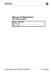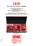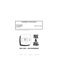
1
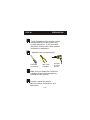
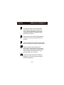
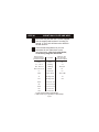
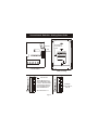
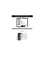
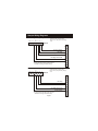
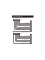
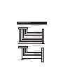
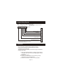
Installation Instructions
TSTATCCREC01
TSTATBBREC01
P474-1100REC
Wireless Reciever
NOTE: Read the entire instruction manual before starting the installation.
HEAT
COOL
FAN
POWER
HEAT
COOL
&
HEAT
PUMP
MULTI-STAGE
Form: IM-TSTAT-10
Cancels:
WIRELESS RECIEVER
Printed in U.S.A.
Catalog No. 13TS-TA36
Table Of Contents
2
3
4
5
7
10
11
PREPARATION
REMOVE OLD THERMOSTAT
MOUNT WALL PLATE & WIRE
CONNECTIONS & SWITCHES
WIRING DIAGRAMS
CALABRATION
TROUBLESHOOTING
CAUTION
Follow Installation Instructions carefully.
DISCONNECT POWER TO THE HEATER AIR CONDITIONER BEFORE REMOVING
THE OLD THERMOSTAT AND INSTALLING
THE NEW THERMOSTAT.
WARNING
This receiver is designed to operate @
0-70 C
FCC ID MUH-T10016
This device complies with Part 15 of the FCC rules.
Operation is subject to the following two conditions:
(1) this device may not cause harmful interference,
and (2) this device must accept any interference
received, including interference that may cause
undesired operation.
Page 1
STEP #1
Cool
70
Fan Auto
12:00
Set
70
Proper installation of the receiver will be
accomplished by following these step
by step instructions. If you are unsure
about any of these steps, call a qualified
technician for assistance.
MODE
FAN
Cool
70
Fan Auto
12:00
Set
70
Assemble tools as shown below.
MODE
FAN
Flat Blade
Screwdriver
Cool
70
Fan Auto
70
MODE
FAN
Drill with
3/16 inch
Drill Bit
Set
70
Make sure your Heater/Air Conditioner
is working properly before beginning
installation of the receiver.
FAN
Cool
Wire cutter
& Stripper
12:00
MODE
Fan Auto
PREPARATION
12:00
Set
70
Carefully unpack the receiver.
Save the screws, wall anchors, and
instructions.
Page 2
STEP #2
Cool
70
Fan Auto
12:00
Set
70
Turn off the power to the Heating/Air
Conditioning system at the main fuse
panel. Most residential systems have
a separate breaker for disconnecting
power to the furnace.
MODE
FAN
Cool
70
Fan Auto
12:00
Set
70
Remove the cover of the old thermostat.
If it does not come off easily check for
screws.
MODE
FAN
Cool
70
Fan Auto
12:00
Set
70
Loosen the screws holding the thermostat
base or subbase to the wall, and lift away.
MODE
FAN
Cool
70
Fan Auto
12:00
Set
70
Disconnect the wires from the old
thermostat. Tape the ends of the wires
as you disconnect them, and mark them
with the letter of the terminal for easy
reconnecting to the receiver.
MODE
FAN
Cool
70
Fan Auto
MODE
FAN
REMOVE OLD THERMOSTAT
12:00
Set
70
Keep the old thermostat for reference
purposes, until your new thermostat is
functioning properly.
Page 3
STEP #3
Cool
70
Fan Auto
12:00
Set
70
MODE
FAN
Cool
70
Fan Auto
MODE
FAN
12:00
Set
70
MOUNT WALL PLATE AND WIRE
Mount the wall plate with the 2 screws supplied.
Use the supplied wall anchors if mounting on
drywall. A 3/16" hole will have to be drilled for
the wall anchors.
If the terminal designations on your old
thermostat do not match those on the
new thermostat, refer to the chart below,
or the wiring diagrams that follow.
Wire from the
old thermostat
terminal marked
Function
G or F
Fan
Y1, Y or C
Cooling
W1, W or H
Heating
Install on the
new receiver
terminal marked
G
Y1
W1,O,B
Rh, R, M, Vr, A
Power
C
Common
C*
R
O/B
Rev. Valve
W1,O,B**
Y2
2nd Stage Cool
Y2
W2
2nd Stage Heat
W2
RS+5
Remote Sensor +5vdc
RS
Remote Sensor Signal
RS G
Remote Sensor Ground
CK1
Dry Contact Switch
CK2
Dry Contact Switch
* C may not be used on all systems.
** O/B is used if your system is a Heat Pump.
Page 4
Connections & Switches - Setting House Code
Antenna
ON
OFF
1
2
4
8
16
32
EH
HP
Terminals for
Connection to
HVAC
Dip
Switches
W1
O
C G Y1 B R Y2 W2
Circuit Board
Rear Housing
Add all ON switches to
arrive at HOUSE CODE
number. All thermostats
communicating with this
receiver must have the
same House Code #.
All # switches off = 0
Page 5
1
2
4
8
16
32
EH
HP
O/B
ON
ON Indicator
OFF
ON
OFF
1
2
4
8
16
32
EH
HP
O/B
Example:
House Code 10,
2+8=10
Connections & Switches - Heat Pump
Circuit Board
1
2
4
8
16
32
EH
HP
OFF
ON
Dip
Switches
Antenna
Heat Pump
ON
OFF
1
2
4
8
16
32
EH
HP
O/B
ON Indicator
To configure the receiver
for heat pump operation
Slide HP switch to the
ON position as shown.
Reversing Valve polarity
(O or B) can also be set.
OFF = O, ON = B
Page 6
Sample Wiring Diagrams
5 Wire, 1 Stage Cooling, 1 Stage Gas Heat
O
W2 Y2 R W1 Y1 G
Residential Gas or Electric Heat *,
Electric Cool, split systems & package
units
C
Receiver
L
E
24 vac common
C
fan relay
compressor relay
Y1
G
O
1st stage heat circuit
24 vac return
* If using electric heat this option must be
selected on during advanced setup.
W1
R
Y2
W2
4 Wire, 1 Stage Cooling, 1 Stage Gas Heat
O
W2 Y2 R W1 Y1 G
Residential Gas or Electric Heat *,
Electric Cool, split systems & package
units
C
Receiver
L
E
C
fan relay
compressor relay
G
Y1
O
1st stage heat circuit
24 vac return
* If using electric heat this option must be
selected on during advanced setup.
Page 7
W1
R
Y2
W2
Sample Wiring Diagrams
6 Wire, 2 Stage Cooling, 1 Stage Heat
O
W2 Y2 R W1 Y1 G
Residential 2 Stage Cooling, with
Gas or Electric Heat*
C
Receiver
L
E
24 vac common
C
fan relay
compressor relay
Y1
G
O
1st stage heat circuit
24 vac return
2nd stage compressor relay
* If using electric heat, this option must
be selected during advanced setup.
W1
R
Y2
W2
6 Wire, 1 Stage Cooling, 2 Stage Heat
O
W2 Y2 R W1 Y1 G
C
Residential & commercial 1 Stage Cooling,
with 2 Stage Gas or Electric Heat*
Receiver
L
E
24 vac common
C
fan relay
compressor relay
Y1
G
O
1st stage heat circuit
24 vac return
W1
R
Y2
2nd stage heat circuit
Page 8
W2
Sample Wiring Diagrams
Commercial Gas or Electric Heat ***,
Electric Cool, split systems & package units
including Commercial Heat Pumps **
7 Wire, 2 Stage Cooling, 2 Stage Heat
O
W2 Y2 R W1 Y1 G
C
Receiver
L
E
24 vac common
C
fan relay
compressor relay
Y1
G
O
1st stage heat circuit
24 vac return
2nd stage compressor relay
2nd stage heat circuit
** Commercial heat pumps do not have
*** If using electric heat, this option must
the heat pump turned on in advanced setup.
be selected on during advanced setup.
W1
R
Y2
W2
5 Wire, 1 Stage Cooling, 1 Stage Heat - Heat Pump*
O
W2 Y2 R W1 Y1 G
No auxiliary heat, residential Heat Pumps ,
split systems & package units
C
Receiver
L
E
24 vac common
C
fan relay
compressor relay
G
Y1
reversing valve
O
W1
24 vac return
* If using residential heat pump, this option
must be selected on during advanced setup.
R
Y2
W2
Page 9
Sample Wiring Diagram
6 Wire, 1 Stage Cooling, 2 Stage Heat, Heat Pump *
O
W2 Y2 R W1 Y1 G
C
Most residential split and package heat pumps
with auxiliary heat
Receiver
L
E
24 vac common
C
fan relay
compressor relay
Y1
1st stage heat circuit
G
O
W1
24 vac return
R
Y2
2nd stage heat circuit
W2
* The heat pump option must be selected
on during advanced setup.
Calibration
Every thermostat is calibrated before it leaves the factory.
Under normal circumstances there will never be a need to
recalibrate the thermostat again.
To accommodate special needs, the thermostat may be recalibrated
following these steps:
1. While holding the mode button in, press the down button for
2 seconds. After all the icons in the display appear, release
the buttons.
2. Press the mode button.
3. Press the up or down buttons until the flashing number
equals the current room temperature.
4. Press the mode button to return to normal operation.
Page 10
TROUBLESHOOTING
Cool
70
Fan Auto
12:00
Set
70
SYMPTOM: When using 4 wires (R, G, W, Y),
the air conditioning or heat equipment tries
repeatedly to turn on, but cannot. At
times the display dims or disappears.
CAUSE: There is not enough power available
to "power share".
REMEDY: Connect a 270 ohm, 10 watt power
resistor at the furnace as shown below.
MODE
FAN
Note: 2 resistors may be used at the same time.
For Problem A/C
R
G
W
Y
For Problem Heat
C
R
TR300-10w
Cool
70
Fan Auto
70
MODE
FAN
Y
C
TR300-10w
Set
70
SYMPTOM: The air conditioning does not
attempt to turn on.
CAUSE: The compressor timer lockout may
prevent the air conditioner from
turning on, for a period of time.
REMEDY: Consult the Owner's Manual in
the Setup section to defeat the
cycles per hour and compressor
timeguard.
FAN
Cool
W
12:00
MODE
Fan Auto
G
12:00
Set
70
SYMPTOM: The display is blank.
CAUSE: Lack of proper power.
REMEDY: Make sure power is turned on to
the furnace and 24vac between R & W.
If C is used, 24vac between R & C.
Page 11
TROUBLESHOOTING
Cool
70
Fan Auto
12:00
Set
70
SYMPTOM: When controlling a residential heat
pump, and asking for cooling, the heat
comes on.
CAUSE: Heat pump is not selected "on" in the
Advanced Setup.
REMEDY: Select heat pump on during Advanced
Setup programming. Consult the Owner's
Manual.
MODE
FAN
Cool
70
Fan Auto
MODE
FAN
12:00
Set
70
SYMPTOM: When calling for cooling, both
the heat and cool come on.
CAUSE: The Advanced Setup is configured
to control a heat pump, and the hvac
the thermostat is controlling is a
"conventional" (non heat pump)
system.
REMEDY: Consult the Owner's Manual in
the Advanced Setup section to turn
off the heat pump.
INSTALLATION NOTES
For best operation make sure the antenna is fully extended
outside of the plastic case. When mounting on a wall, fully
extend the antenna inside of the wall.
When mounting the receiver inside a ‘package unit’ make
sure the antenna is outside of the metal enclosure. This may
be accomplished by drilling a 1/4” hole through the package
unit sheet metal, just below the receiver, so the antenna may
extend outside the unit.
Page 12
P/N 88-264