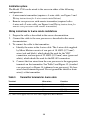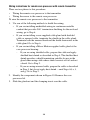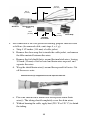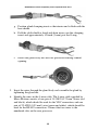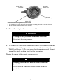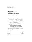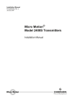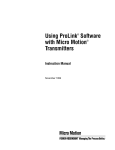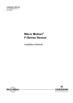
1
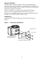
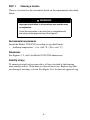
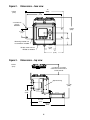
Quick Reference Guide
P/N 20001008, Rev. B
August 2005
Model 3700 Transmitter
(MVD) or
Model 3350 Peripheral
Installation Instructions for
Field-Mount
For technical support, phone the support center nearest you:
•
In the U.S.A., phone 1-800-522-MASS
(1-800-522-6277)
•
In Canada and Latin America, phone
(303) 527-5200
•
In Asia, phone (65) 6770-8155
•
In the U.K., phone 0800 - 966 180 (toll-free)
•
Outside the U.K., phone +31 (0) 318 495 670
BEFORE YOU BEGIN
This quick reference guide explains basic installation guidelines for
installing the Micro Motion® Model 3350/3700 MVD applications
platform.
For information on I.S. applications, refer to Micro Motion approval
documentation.
For complete instructions about configuration, maintenance, and service,
refer to the instruction manual shipped with the transmitter.
WARNING
Improper installation in a hazardous area can cause
an explosion.
For information about hazardous applications, refer to
Micro Motion approval documentation, shipped with the
transmitter or available from the Micro Motion web site.
WARNING
Hazardous voltage can cause severe injury or death.
Install transmitter and complete all wiring before
supplying power.
CAUTION
Improper installation could cause measurement error
or meter failure.
Follow all instructions to ensure transmitter will operate
correctly.
©2005, Micro Motion, Inc. All rights reserved. Micro Motion is a registered trademark of Micro Motion, Inc. The Micro
Motion and Emerson logos are trademarks of Emerson Electric Co. All other trademarks are property of their respective
owners.
1
European installations
This Micro Motion product complies with all applicable European
directives when properly installed in accordance with the instructions in
this quick reference guide. Refer to the EC declaration of conformity for
directives that apply to this product.
The EC declaration of conformity, with all applicable European
directives, and the complete ATEX Installation Drawings and
Instructions are available on the web at www.micromotion.com/atex or
through your local Micro Motion support center.
Installation kit
The Model 3350/3700 installation kit includes the parts shown in
Figure 1.
Figure 1.
Field-mount installation kit
Mounting bracket
4 x Lock washer
Transmitter can be oriented
on bracket. See Step 3.
4 x Flat washer
4 x M8x16 Bolt assemblies
2
STEP 1.
Choosing a location
Choose a location for the transmitter based on the requirements described
below.
WARNING
Improper installation in a hazardous area could cause
an explosion.
Install the transmitter in an area that is compatible with
the rating on the approvals tag. See Figure 3.
Environmental requirements
Install the Model 3350/3700 according to specified limits:
•
Ambient temperature: –4 to +140 °F (–20 to +60 °C)
Dimensions
See Figures 2, 3, and 4 for Model 3350/3700 dimensions.
Visibility of tags
To ensure personal and system safety, all tags attached to the housing
must remain visible. Clean them as often as necessary. Replace tags that
are damaged, missing, or worn. See Figure 3 for location of approvals tag.
3
Figure 2.
Dimensions – face view
12
(305)
inches
(mm)
11
(279)
4 x 5/16-inch
(9 mm)
diameter
9 3/16
(234)
2 13/16
(71)
4
(102)
Mounting bracket can
be rotated as needed
3 5/8
(92)
Display cover can be
rotated as needed
6
(152)
Figure 3.
Dimensions – top view
inches
(mm)
5 1/16-inch (129 mm)
clearance for removal of
circuit boards
Approvals tag
11 5/16
(288)
6 1/8
(158)
8 11/16
(221)
15 1/2
(394)
4
Figure 4.
Dimensions – conduit openings view
inches
(mm)
2 x 15/16
(24)
1 7/8
(48)
2 x 2 13/17
(71)
Case ground
5 x 3/4–14 NPT
or
5 x M20 x 1.5 – 6H
10 3/8
(265)
7 1/2
(191)
5 3/4
(147)
Mounting surface
Cable lengths
Maximum cable length from the sensor to the Model 3700 transmitter
depends on the installation type and cable type:
•
4-wire remote transmitter: see Figure 5, then refer to Table 1 for
maximum length of the 4-wire cable.
•
Remote core processor with remote transmitter: see Figure 6, then
refer to Table 1 for maximum length of the 4-wire cable and the
9-wire cable.
If you are installing the Model 3350 applications peripheral in
combination with a transmitter, the maximum cable length from the
transmitter’s frequency output to the Model 3350’s frequency input is
500 feet (150 meters).
5
Figure 5.
4-wire remote transmitter
Sensor
Model 3700
4-wire cable
Core processor
(standard or enhanced)
Figure 6.
Remote core processor with remote transmitter
Model 3700
Sensor
4-wire cable
Table 1.
Core processor
(standard only)
9-wire cable
Junction box
Maximum cable lengths
Cable type
Wire gauge
Maximum length
Micro Motion 9-wire
Not applicable
60 feet (20 meters)
Micro Motion 4-wire
Not applicable
1000 feet (300 meters)
22 AWG (0,35 mm2)
300 feet (90 meters)
20 AWG (0,5 mm2)
500 feet (150 meters)
User-supplied 4-wire
•
•
Power wires (VDC)
Signal wires (RS-485)
Cable from transmitter’s FO
to Model 3350’s FI(1)
18 AWG (0,8 mm2)
1000 feet (300 meters)
22 AWG (0,35 mm2) or larger
1000 feet (300 meters)
Not applicable
500 feet (150 meters)
(1) Applies only to the Model 3300 applications peripheral when receiving frequency input
from a remote Micro Motion transmitter such as an IFT9701 or RFT9739.
6
STEP 2.
Preparing conduit openings for ATEX Zone 1
If the Model 3350/3700 carries an ATEX Zone 1 approval:
1. Remove thread protectors from conduit openings (see Figure 7).
2. Install factory-supplied cable glands or user-supplied EExe cable
entry devices in conduit openings that are in use.
3. Install EExe plugs in conduit openings that are not in use.
STEP 3.
Orienting the Model 3350/3700 (optional)
The Model 3350/3700 can be oriented on the mounting bracket as
needed, and the display cover can be rotated on the applications platform.
Figure 7 provides orientation examples.
To orient the Model 3350/3700:
1. Use the four supplied mounting bolt assemblies.
2. Using a 13 mm hex wrench, install the bolt assemblies to 12 ft-lb
(16 Nm) of torque.
To rotate the display cover, if needed, see the transmitter installation
manual.
Figure 7.
Orientation examples
Conduit openings
left
Conduit openings for
intrinsically safe
sensor wiring
Display cover
Conduit openings for
non-intrinsically safe
input/output wiring
Conduit openings
right
7
Conduit openings
down
STEP 4.
Mounting the applications platform
For flat-surface mounting, see Figure 8.
For pole mounting, see Figure 9.
Figure 8.
•
•
•
Mounting to a flat surface
Mount all four bolts to the same surface.
If mounting surface is not flat, use
washers to shim the bracket.
Do not secure bolts to separate beams,
girders, wall studs, etc., which can move
independently.
4 x 5/16-inch or M8 bolt
(user-supplied)
Figure 9.
Mounting to a pole
4 x 5/16 inch nut
(user-supplied)
2 x 5/16-inch U bolt for
2-inch pipe (user-supplied)
8
STEP 5.
Mounting the core processor
This step is required only for remote core processor with remote
transmitter installations (see Figure 6). If you have a 4-wire remote
installation, go to Step 6.
Figure 10 shows the remote core processor and mounting bracket. Using
the mounting bracket, mount the core processor in a location compatible
with the cable length requirements discussed in Step 1.
Figure 10. Remote core processor components
Core processor lid
Upper conduit ring
Core processor
Mounting bracket
Lower conduit ring
End-cap
STEP 6.
Connecting input and output wiring
Figure 11 shows the location of the wiring terminals on the Model
3350/3700.
1. Using a flat-head screwdriver, loosen the four captive screws that
secure the display cover to the housing.
2. Connect input/output wiring to the appropriate terminals on the gray
terminal block. Refer to Table 2 and to the label attached to the back
of the display cover (shown in Figure 12).
•
Use 22 to 16 AWG (0,35 to 1,5 mm2) twisted-pair shielded wire.
•
Ground the cable shields at a single point only.
•
If more than two wires must be connected to a single terminal, use
a butt splice or spade lug to connect the wires.
9
Figure 11. Wiring terminals
Circuit board
compartment
Lockout device
(not supplied with all units)
Non-intrinsically safe
input/output wiring
terminals
(gray terminal block)
Intrinsically safe
sensor wiring terminals
(blue terminal block)
Wiring compartment
Should remain closed
while power is on
Power supply
ground
Label for sensor
wiring terminals
(see Figure 12)
Label for input/output
wiring terminals
Display cover
Table 2.
Input/output wiring terminals
Terminal number
Designation
1–
2+
3–
4+
Primary 4–20 mA output / HART
Secondary 4–20 mA output
5–
6+
Frequency input
5–
7+
Discrete input 1
5–
8+
Discrete input 2
11 (B line)
12 (A line)
RS-485 output
20 –
16 +
Discrete output 3
20 –
17 +
Discrete output 2
20 –
18 +
Discrete output 1
20 –
19 +
Frequency output
10
Figure 12. Wiring terminal labels
Model 3350/3700 with AC
power supply
Model 3350/3700 with DC
power supply
Terminal 9:
line
(L or L2)
Terminal 9:
positive
Terminal 10:
neutral
(N or L1)
Terminal 10:
negative
STEP 7.
Connecting the Model 3700 to the sensor
If you are installing the Model 3350 applications peripheral, this step is
not required. Go to Step 8.
To connect the Model 3700 transmitter to a Micro Motion sensor, follow
the instructions in this section.
11
Installation options
The Model 3700 can be wired to the sensor in either of the following
configurations:
•
4-wire remote transmitter (requires a 4-wire cable; see Figure 5 and
Wiring instructions for 4-wire remote installations)
•
Remote core processor with remote transmitter (requires both a
4-wire and a 9-wire cable; see Figure 6 and Wiring instructions for
remote core processor with remote transmitter)
Wiring instructions for 4-wire remote installations
1. Prepare the cable as described in the sensor documentation.
2. Connect the cable to the core processor as described in the sensor
documentation.
3. To connect the cable to the transmitter:
a. Identify the wires in the 4-wire cable. The 4-wire cable supplied
by Micro Motion consists of one pair of 18 AWG (0,75 mm2)
wires (red and black), which should be used for the VDC
connection, and one pair of 22 AWG (0,35 mm2) wire (green and
white), which should be used for the RS-485 connection.
b. Connect the four wires from the core processor to the appropriate
terminals on the transmitter. See Table 3 and Figure 13 (standard
core processor) or Figure 14 (enhanced core processor). No bare
wires should remain exposed. Do not ground the shield or drain
wire(s) at the transmitter.
Table 3.
Transmitter terminals for 4-wire cable
Terminal
Wire color(1)
Function
13
Red
VDC+
14
Black
VDC–
15
White
RS-485A
16
Green
RS-485B
(1) Wire colors apply only to 4-wire cable supplied by Micro Motion.
12
Figure 13. 4-wire cable to Model 3700 – standard core processor
Core processor
terminals
VDC+
(Red)
RS-485B
(Green)
4-wire cable
Maximum cable length:
see Table 1
Model 3700 terminals
blue terminal block
(see Figure 11)
User-supplied or
factory-supplied cable
VDC–
(Black)
RS-485A
(White)
16 RS-485B (Green)
15 RS-485A (White)
14 VDC– (Black)
13 VDC+ (Red)
Figure 14. 4-wire cable to Model 3700 – enhanced core processor
Core processor
terminals
4-wire cable
Maximum cable length:
see Table 1
Model 3700 terminals
blue terminal block
(see Figure 11)
RS-485A (White)
RS-485B (Green)
User-supplied or
factory-supplied cable
VDC– (Black)
VDC+ (Red)
16 RS-485B (Green)
15 RS-485A (White)
14 VDC– (Black)
13 VDC+ (Red)
13
Wiring instructions for remote core processor with remote transmitter
There are two phases to this procedure:
•
Wiring the remote core processor to the transmitter
•
Wiring the sensor to the remote core processor
To wire the remote core processor to the transmitter:
1. Use one of the following methods to shield the wiring:
•
If you are installing unshielded wiring in continuous metallic
conduit that provides 360° termination shielding for the enclosed
wiring, go to Step 6.
•
If you are installing a user-supplied cable gland with shielded
cable or armored cable, terminate the shields in the cable gland.
Terminate both the armored braid and the shield drain wires in the
cable gland. Go to Step 6.
•
If you are installing a Micro Motion-supplied cable gland at the
core processor housing:
-
If you are using shielded cable, prepare the cable and apply
shielded heat shrink as described in Step 4. The shielded heat
shrink provides a shield termination suitable for use in the
gland when using cable whose shield consists of foil and not
a braid. Go to Step 2.
-
If you are using armored cable, prepare the cable as described
in Step 4, but do not apply heat shrink – omit Steps 4d, e, f,
and g. Go to Step 2.
2. Identify the components shown in Figure 10. Remove the core
processor lid.
3. Slide the gland nut and the clamping insert over the cable.
14
4 1/2 in
(114 mm)
3/4 in
(19 mm)
Gland nut
Gland clamping
insert
7/8 in
(22 mm)
7/8 in
(22 mm)
Gland body
Shielded
heat shrink
4. For connection at the core processor housing, prepare shielded cable
as follows (for armored cable, omit steps d, e, f, g):
a. Strip 4 1/2 inches (114 mm) of cable jacket.
b. Remove the clear wrap that is inside the cable jacket, and remove
the filler material between the wires.
c. Remove the foil shield that is around the insulated wires, leaving
3/4 inch (19 mm) of foil or braid and drain wires exposed, and
separate the wires.
d. Wrap the shield drain wire(s) around the exposed foil twice. Cut
off the excess wire.
Shield drain wire(s) wrapped twice around exposed shield foil
e. Place the shielded heat shrink over the exposed shield drain
wire(s). The tubing should completely cover the drain wires.
f.
Without burning the cable, apply heat (250 °F or 120 °C) to shrink
the tubing.
15
Shielded heat shrink completely covers exposed drain wires
g. Position gland clamping insert so the interior end is flush with the
heat shrink.
h. Fold the cloth shield or braid and drain wires over the clamping
insert and approximately 1/8 inch (3 mm) past the O-ring.
i.
Install the gland body into the core processor housing conduit
opening.
5. Insert the wires through the gland body and assemble the gland by
tightening the gland nut.
6. Identify the wires in the 4-wire cable. The 4-wire cable supplied by
Micro Motion consists of one pair of 18 AWG (0,75 mm2) wires (red
and black), which should be used for the VDC connection, and one
pair of 22 AWG (0,35 mm2) wire (green and white), which should be
used for the RS-485 connection. Connect the four wires to the
numbered slots on the core processor.
16
Power supply +
(Red wire)
RS-485B
(Green wire)
RS-485A
(White wire)
Power supply –
(Black wire)
Core processor housing internal ground screw
• For connections to earth ground (if core processor cannot be grounded via sensor piping and
local codes require ground connections to be made internally)
• Do not connect shield drain wires to this terminal
7. Reinstall and tighten the core processor lid.
WARNING
Twisting the core processor will damage the sensor.
Do not twist the core processor.
8. To connect the cable to the transmitter, connect the four wires from the
core processor to the appropriate terminals on the transmitter. See
Table 3 and Figure 13. No bare wires should remain exposed. Do not
ground the shield or drain wire(s) at the transmitter.
To wire the sensor to the remote core processor:
CAUTION
Allowing the shield drain wires to contact the sensor
junction box can cause meter errors.
Do not allow the shield drain wires to contact the sensor
junction box.
17
1. Refer to Micro Motion’s 9-Wire Flowmeter Cable Preparation and
Installation Guide for instructions on cable shielding and
preparation:
•
At the sensor end, follow the instructions for your cable type.
•
At the core processor end, follow the instructions for your cable
type with an MVD transmitter.
2. To connect the wires, refer to Micro Motion’s 9-Wire Flowmeter
Cable Preparation and Installation Guide and follow the instructions
for your sensor with an MVD transmitter. Additional information for
connecting the wires at the core processor is provided below:
a. Identify the components shown in Figure 10.
a. Remove the core processor’s end-cap.
b. Insert the 9-wire cable through the conduit opening.
c. Connect the wires to the plugs supplied with the core processor.
d. Insert the plugs into the sockets inside the lower conduit ring. See
Figure 15.
Figure 15. 9-wire cable to core processor
9-wire cable from
sensor
Core processor
Ground screw
Black
Black
(Drains from
all wire sets)
Brown
Violet
Yellow
Brown
Red
Green
White
Blue
Gray
Orange
Violet
Yellow
Red
Green
White
Plug and
socket
Mounting screw
Blue
Gray
Orange
3. Ground the cable. If using jacketed cable:
a. Ground the shield drain wires (the black wire) only on the core
processor end, by connecting it to the ground screw inside the
lower conduit ring. Do not ground to the core processor’s
mounting screw. Do not ground the cable at the sensor junction
box.
18
If using shielded or armored cable:
a. Ground the shield drain wires (the black wire) only on the core
processor end, by connecting it to the ground screw inside the
lower conduit ring. Do not ground to the core processor’s
mounting screw. Do not ground the cable at the sensor junction
box.
b. Ground the cable braid on both ends, by terminating it inside the
cable glands.
4. Ensure integrity of gaskets, grease all O-rings, then close the junction
box housing and core processor end-cap, and tighten all screws.
CAUTION
Damaging the wires that connect the transmitter to
the sensor can cause measurement error or meter
failure.
To reduce the risk of measurement error or meter failure,
when closing the housings on the sensor and core
processor, make sure that the wires are not caught or
pinched.
STEP 8.
Connecting power supply wiring
CAUTION
Improper wiring installation can cause device failure
or measurement error.
• To avoid device failure or measurement error, do not
install power supply wiring in the same cable tray or
conduit as input/output wiring.
• Shut off power supply before installing the applications
platform.
• Make sure power supply voltage matches voltage that
is indicated on power supply wiring terminals. See
Figure 12.
19
Connect the Model 3350/3700 to a power supply as follows:
1. Use 18 to 12 AWG (0,75 to 4,0 mm2) wire.
2. Using a flat-head screwdriver, loosen the captive screws that secure
the display cover to the housing.
3. Ground the transmitter as follows:
•
Connect the ground wire to the green screw (power supply
ground; see Figure 11).
•
Connect the power supply ground wire directly to earth ground.
•
Keep all ground leads as short as possible.
•
Ground wiring must have less than 1 ohm impedance.
4. Connect wires to terminals 9 and 10 on the gray terminal block (see
Figures 11 and 12).
5. Close the display cover and tighten the screws.
6. A user-supplied switch may be installed in the power supply line. For
compliance with low-voltage directive 73/23/EEC (European
installations), a switch in close proximity to the Model 3350/3700 is
required.
20
21
22
©2005, Micro Motion, Inc. All rights reserved. P/N 20001008, Rev. B
*20001008*
Visit us on the Internet at www.micromotion.com
Micro Motion Inc. USA
Worldwide Headquarters
7070 Winchester Circle
Boulder, Colorado 80301
T (303) 527-5200
(800) 522-6277
F (303) 530-8459
Micro Motion Europe
Micro Motion Asia
Emerson Process Management
Veenendaal
The Netherlands
T +31 (0) 318 495 670
F +31 (0) 318 495 689
Emerson Process Management
1 Pandan Crescent
Singapore 128461
Republic of Singapore
T (65) 6777-8211
F (65) 6770-8003
Micro Motion United Kingdom
Micro Motion Japan
Emerson Process Management Limited
Horsfield Way
Bredbury Industrial Estate
Stockport SK6 2SU U.K.
T 0800 966 180
F 0800 966 181
Emerson Process Management
Shinagawa NF Bldg. 5F
1-2-5, Higashi Shinagawa
Shinagawa-ku
Tokyo 140-0002 Japan
T (81) 3 5769-6803
F (81) 3 5769-6843