1
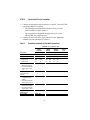
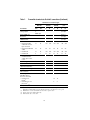
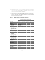
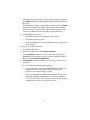
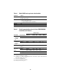
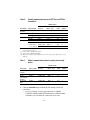
Quick Reference Guide
P/N 20001908, Rev. GA
August 2009
ProLink® II
Installation and Startup
For customer service, phone the support center nearest you:
•
In the U.S.A., phone 800-522-MASS (800-522-6277)
(toll-free)
•
In Canada and Latin America, phone +1 303-527-5200
•
In Asia:
•
-
In Japan, phone 3 5769-6803
-
In other locations, phone +65 6777-8211 (Singapore)
In Europe:
-
In the U.K., phone 0870 240 1978 (toll-free)
-
In other locations, phone +31 (0) 318 495 555
(The Netherlands)
Customers outside the U.S.A. can also send an email to
Micro Motion customer service at:
[email protected]
BEFORE YOU BEGIN
About these instructions
This quick reference guide explains basic installation guidelines for
Micro Motion® ProLink® II software.
For complete instructions about installation and use, refer to the
ProLink II manual.
WARNING
An improper connection between ProLink II and the
transmitter can cause an explosion.
To avoid causing an explosion, be sure to connect
ProLink II to the transmitter using safe methods. To avoid
causing an explosion:
• Do not open a non-intrinsically safe wiring
compartment in a hazardous area.
• Do not use the computer running ProLink II in a
hazardous area.
Note: If you have a Model 2700 transmitter with transmitter software
earlier than v3.4, and you have the concentration measurement
application installed, you cannot access the concentration measurement
functions with ProLink II v2.1 or later. Contact Micro Motion for
alternative solutions.
©2009, Micro Motion, Inc. All rights reserved. ELITE, ProLink, and the Micro Motion logo are registered trademarks of Micro
Motion, Inc., Boulder, Colorado. MVD and MVD Direct Connect are trademarks of Micro Motion., Inc., Boulder, Colorado.
Micro Motion is a registered trade name of Micro Motion, Inc., Boulder, Colorado. The Emerson logo is a trademark of
Emerson Electric Co. All other trademarks are property of their respective owners.
1
PC requirements
To install and run ProLink II, your PC must meet or exceed the following
requirements:
•
200 MHz Pentium processor
•
One of the following:
-
Windows XP with Service Pack 1 and 128MB RAM
-
Windows 2000 with Service Pack 3 and 128MB RAM
•
80MB of available hard disk space
•
Video with support for 256 or more colors
•
CD-ROM Drive
•
An available serial port or USB port
Installation kits
Micro Motion provides ProLink II installation kits for the following
connection types:
•
RS-485 to serial port (RS-232)
•
RS-485 to USB port
•
Bell 202 to serial port (RS-232)
•
Bell 202 to USB port
The installation kits include signal converters and assorted adapters,
cables, and testers. If you need a ProLink II installation kit, contact Micro
Motion.
Note: If you do not use a signal converter supplied by Micro Motion, it is
your responsibility to ensure that your equipment provides equivalent
functionality. See the ReadMe.txt file in the ProLink II installation
directory, or contact Micro Motion customer support for assistance or
additional information.
Note: A Windows driver is required for correct operation of the Bell 202
USB signal converter. This driver is provided with the installation kit.
Ensure that the driver is installed before attempting to connect through
the USB port. If this driver is not installed, Windows will not recognize
the USB converter when it is plugged into the USB port.
2
STEP 1.
Install the ProLink II software
To install ProLink II software:
1. Insert the ProLink II CD-ROM into the PC’s CD-ROM drive.
2. If the setup program does not start automatically, locate and run the
SETUP.EXE file. The file is located in the root directory on the
CD-ROM (e.g., D:\setup.exe, where “D” is your CD-ROM drive
letter).
Note: The user who installs the ProLink II software must have permission
to write to the registry.
3. Follow the on-screen instructions to complete the installation. If you
have a previous version of ProLink II installed on your PC, you may
be prompted to remove it before installing the new version.
Warning: The ProLink II site key is associated with a specific disk drive
and specific folder on your PC. If you decide to move ProLink II after
installation, you will have to transfer the license and reinstall ProLink II.
To avoid this step, be sure to install ProLink II into a location that you
can use permanently.
4. Follow the on-screen instructions to generate the temporary license.
This license will allow you to run ProLink II with full functionality for
seven days, starting from the current date and time.
5. A site key is required for a permanent license. Follow the instructions
in the ProLink II manual to obtain and configure a site key.
Warning: The temporary license will expire after seven days, and
ProLink II will not connect to a transmitter. Be sure to configure the site
key before the temporary license expires.
In typical installations, the manual is installed with the ProLink II
program, and can be opened from the Micro Motion folder in the
Windows Start menu. You can also find the ProLink II manual on the
installation CD, in the root directory.
Note: Adobe Acrobat Reader is required to read the ProLink II manual.
The self-extracting setup file for this program is provided in the root
directory of the ProLink II installation CD, if Acrobat Reader is not
already installed on your system. The ProLink II setup program does not
install Acrobat Reader automatically.
3
STEP 2.
Connect the PC to the transmitter
1. Connect the appropriate signal converter to your PC’s serial or USB
port, using adapters as required.
•
For connections using the Bell 202 physical layer, use the
Bell 202–RS-232 signal converter.
•
For connections using the RS-485 physical layer, use the
RS-485–RS-232 signal converter.
2. Connect the two leads of the signal converter to the appropriate
terminals on your transmitter. See Table 1.
Table 1.
Transmitter terminals for ProLink II connections
Terminals for connection type
HART/
Bell 202
Transmitter
PV+
PV–
IFT9701/9703
4-20 +
4-20 –
RFT9712
17
HART/
RS-485
A
B
16
21
22
Modbus/
RS-485
A
B
D22
Service
port
A
B
8
7
RFT9739
•
Rack-mount
Z30
D30
Z22
D22
Z22
•
Field-mount
17
18
27
26
27
26
•
Model 1700/2700
with analog outputs
LFT field-mount with
output option codes
1, 3
1
2
5
6
5
6
Model 1700/2700 with
intrinsically safe
outputs(1)
1
2
8
7
•
1
2
8
7
8
7
8
7
•
•
•
•
Model 2700 with
configurable input/
outputs
LFT field-mount with
output option code 4
Model 2700 with
FOUNDATION™ fieldbus
LFT field-mount with
output option code 6
Model 2700 with
PROFIBUS-PA
Model 2200S
HART clips
4
Table 1.
Transmitter terminals for ProLink II connections (Continued)
Terminals for connection type
HART/
Bell 202
Transmitter
PV+
Model 2400S with
analog outputs
1
2
or
HART clips
HART/
RS-485
PV–
A
B
Modbus/
RS-485
A
B
Service
port
A
B
Service
port clips
Model 2400S with
DeviceNet
Service
port clips
Model 2400S with
PROFIBUS-DP
Service
port clips
Series 3000
•
Panel-mount with
solder-tail or screwtype connectors
c2
a2
c32
a32
c32
a32
c32
a32
•
Panel-mount with I/O
cables
14
15
24
25
24
25
24
25
•
Rack-mount
c2
a2
c32
a32
c32
a32
c32
a32
•
Field-mount
2
1
11
12
11
12
11
12
•
•
Model 1500/2500
LFT DIN rail with
output option codes
2, 5, 8
21
22
33
34
33
34
Model 7826/7828(2)
3
4
Model 7829(2)
3
4
Model
7835/7845/7846/7847(2)
11
12
Model 7835 EXD(2)
3
4
MVD™ Direct Connect™
with no barrier(3)
3
4
MVD Direct Connect
with MVD™ Direct
Connect™ I.S. barrier
•
Connection to
barrier(4)
13
14
•
Connection to core
processor(3)
3
4
3
4
Core processor(3)(5)
(1) If connecting to terminals 1 and 2, terminals must be externally powered, with a
minimum of 250 Ω and 17.5 volts. Requirement does not apply to service port.
(2) Transmitter version with advanced electronics option only.
(3) Connection is not intrinsically safe.
(4) Intrinsically safe connection.
5
(5) Connecting directly to the core processor terminals is supported for sensor-mounted
core processors (4-wire remote installations) or stand-alone core processors (remote
core processor with remote transmitter installations).
3. Add resistance if required. Many HART connections require added
resistance. See Table 2. For additional information, see the ProLink II
manual or the transmitter manual.
Table 2.
Added resistance for ProLink II connections
Resistance range for connection type
Transmitter
HART/
Bell 202
HART/
RS-485(1)
Modbus/
RS-485(1)
IFT9701/9703
250–600 Ω
RFT9712
250–1000 Ω
(1)
Rack-mount
250–1000 Ω
(1)
(1)
Field-mount
250–1000 Ω
(1)
(1)
Model 1700/2700 with
analog outputs
LFT field-mount with
output option codes 1,
3
250–600 Ω
(1)
(1)
Service
port
RFT9739
•
•
•
•
(1)
Model 1700/2700 with
intrinsically safe outputs
250–600 Ω
(1)
•
250–600 Ω
(1)
•
•
•
Model 2700 with
configurable
input/outputs
LFT field-mount with
output option code 4
(1)
Model 2700 with
FOUNDATION fieldbus
LFT field-mount with
output option code 6
(1)
Model 2700 with
PROFIBUS-PA
Model 2200S
250–600 Ω
Model 2400S with
analog outputs
250–600 Ω
(1)
Model 2400S with
DeviceNet
(1)
Model 2400S with
PROFIBUS-DP
(1)
Series 3000
250–600 Ω
(1)
6
(1)
Table 2.
Added resistance for ProLink II connections (Continued)
Resistance range for connection type
HART/
Bell 202
Transmitter
•
•
Model 1500/2500
LFT DIN rail with output
option codes 2, 5, 8
HART/
RS-485(1)
250–600 Ω
Modbus/
RS-485(1)
Service
port
(1)
Model 7826/7828(2)
(1)
MVD Direct Connect
(1)
(1) RS-485 connections may require added resistance if the connection is long-distance or
if there is external noise that interferes with the signal. Add two 120-Ω resistors in
parallel with the output, one at each end of the communication segment.
(2) Transmitter version with advanced electronics option only.
4. For Modbus network connections, ensure that ProLink II is the only
Modbus master currently active on the network.
There are additional methods for connecting ProLink II to your
transmitter, including connecting over a network. See the ProLink II
manual for complete information.
STEP 3.
Configure the connection and connect
To connect to a Model 7826 or Model 7828 (transmitter versions only):
1. Start ProLink II software.
2. In the Connection menu, click Connect to
Densitometer/Viscometer.
3. Set Serial Port to the PC COM port you are using to connect to the
device.
4. If you know the address of the device and you want to communicate
with this product only:
a. Enter the address in the From Address and To Address fields.
b. Click Connect.
5. If you do not know the address, or if you want to communicate with
multiple devices:
a. Enter an address range in the From Address and To Address
fields.
b. Click Connect.
7
ProLink II will poll all addresses in the specified range, and populate
the Found dropdown list with all Model 7826/7828 devices found in
that range.
When polling is complete, select the desired address from the Found
dropdown list and use other ProLink II windows to work with the
associated device. To interact with a different device, return to the
Connection window and select the address of the new device.
6. If ProLink II fails to connect:
•
Try adding resistance to the connection. See Table 2.
•
Swap the leads and try again.
•
Ensure that ProLink II is the only Modbus master currently active
on the network.
To connect to all other transmitters:
1. Start ProLink II software.
2. In the Connection menu, click Connect to Device.
3. Use the Protocol parameter to specify your connection type. For
HART/Bell 202 connections using the converter supplied by Micro
Motion, enable Converter Toggles RTS.
4. Set Serial Port to the PC COM port you are using to connect to the
transmitter.
5. Specify additional communication parameters.
•
If you are making a service port or HART/Bell 202 connection,
default values are used for all remaining communication
parameters. No configuration is required.
•
If you are connecting to an MVD Direct Connect system, set the
remaining communication parameters to any of the supported
values listed in Table 3. The core processor auto-detects incoming
communications settings and switches to match.
8
•
•
If you are connecting to any Model 2400S transmitter using the
service port:
-
For point-to-point connections, you can use a service port
connection type.
-
For multidrop network connections, you can use any RS-485
connection type and specify the transmitter’s Modbus address.
The transmitter auto-detects incoming communications
settings and switches to match. The service port autodetection limits are described in Table 4.
For all other connection types:
-
Default values for Series 1000/2000/3000 transmitters and LF
meters are listed in Table 5.
-
Default values for RFT97xx and IFT97xx transmitters are
listed in Table 6. If your transmitter is not using default
values, refer to site documentation for the values you are
using.
-
Default values for density and viscosity meters are listed in
Table 7.
Note: ProLink II automatically sets data bits appropriately for the
configured protocol. Even though a data bits parameter may be
configured in the transmitter, you do not need to configure it in
ProLink II. HART protocol is always 8 data bits. If your transmitter is
configured for Modbus with 7 data bits, specify Modbus ASCII; if your
transmitter is configured for Modbus with 8 data bits, specify Modbus
RTU.
Table 3.
MVD Direct Connect auto-detection limits
Parameter
Option
Protocol
Modbus RTU (8-bit)
Modbus ASCII (7-bit)
Baud rate
Standard rates from 1200 to 38,400
Parity
Even, odd, none
Stop bits
1, 2
9
Table 4.
Model 2400S service port auto-detection limits
Parameter
Option
Protocol
Modbus RTU (8-bit)
Modbus ASCII (7-bit)
Address
Responds to both:
• Service port address (111)
• Configured Modbus address (default=1)
Baud rate
Standard rates from 1200 to 38,400
Stop bits
0, 1
Parity
Even, odd, none
Table 5.
Default communication values for Series 1000/2000/3000
transmitters and LF meters
Default values
Transmitter
Physical layer
Protocol
Baud
Stop
bits
Parity
Address
•
Model
1500/2500
LFT DIN
rail
Bell 202(1)
HART
1200
1
odd
0
RS-485(2)
Modbus RTU
9600
1
odd
1
Model
1700/2700
LFT fieldmount
Bell 202(1)
HART
1200
1
odd
0
RS-485(2)(3)
HART
1200
1
odd
0
Model 2200S
Bell 202(4)
HART
1200
1
odd
0
•
•
•
RS-485(5)
Model 2400S
with analog
outputs
Bell 202(1)
HART
1200
1
odd
0
RS-485(6)
Modbus
(RTU or ASCII)
Autodetect
Autodetect
Autodetect
1
Series 3000
Bell 202(1)
HART
1200
1
odd
0
RS-485(2)
Modbus RTU
9600
1
odd
1
(1) Connection to primary mA output, or to HART clips if available.
(2) Connection to RS-485 terminals.
(3) Available only on Model 1700/2700 transmitters with analog outputs or LF transmitters
with output option codes 1 or 3.
(4) Connection to HART clips.
(5) Connection to RS-485 terminals.
(6) Connection to service port.
10
Table 6.
Default communication values for RFT97xx and IFT97xx
transmitters
Default values
Transmitter
Physical layer
Protocol
Baud
Stop
bits
Parity
Address
IFT9701/
IFT9703(1)
Bell 202(2)
HART
1200
1
odd
0
RFT9712
Bell 202(2)
HART
1200
1
odd
0
RS-485(3)
HART
1200
1
odd
0
Bell 202(2)
HART
1200
1
odd
0
RS-485(3)
HART
1200
1
odd
0
Bell 202(2)
HART
1200
1
odd
0
RFT9739 v2
RFT9739 v3
RS-485(3)(4)
•
Std. comm
Modbus RTU
9600
1
odd
1
•
User defined
HART
1200
1
odd
0
(1) IFT9701/9703 communication parameters are not configurable. The settings shown
here are always in effect.
(2) Connection to primary mA output.
(3) Connection to RS-485 terminals.
(4) Dip switch settings on the transmitter are used to select either Std. comm or User
defined.
Table 7.
Default communication values for density and viscosity
meters
Default values
Transmitter
Physical layer
Protocol
Baud
Stop
bits
Parity
Address
Model
7826/28
RS-485(1)
Modbus RTU
9600
2
none
1
Model 7829
RS-485(1)
Modbus RTU
9600
2
none
1
Model
7835/7845/78
46/7847
RS-485(1)
Modbus RTU
9600
2
none
1
Model 7835
EXD
RS-485(1)
Modbus RTU
9600
2
none
1
(1) Connection to RS-485 terminals.
6. Click the Connect button. ProLink II will attempt to make the
connection.
•
If you are making a service port connection to a Model
1700/2700, Model 2400S, LFT field-mount, or Model 2200S
transmitter, you can make the connection at any time.
11
•
If you are connecting to a Model 1500/2500, Series 3000, or LFT
DIN rail mount transmitter, the RS-485 terminals are available in
service port mode for 10 seconds after transmitter power-up.
-
If a service port connection is made during this interval, the
terminals will remain in service port mode until the next
power cycle, and you can make a service port connection at
any time.
-
If no connection is made during this interval, the terminals
switch to RS-485 mode and you can make an RS-485
connection at any time.
If the terminals are in one mode and you want to use the other
mode, you must power cycle the transmitter to reset the mode,
then make the appropriate connection at the appropriate time.
•
If you are using any other connection type, you can make the
connection at any time.
7. If ProLink II fails to connect:
•
Try adding resistance to the connection. See Table 2, the
ProLink II manual, or the transmitter manual.
•
For Modbus connections, swap the leads and try again.
•
For Modbus connections, ensure that ProLink II is the only
Modbus master currently active on the network.
•
If you are using Modbus ASCII protocol to connect to the
Model 2400S transmitter with analog outputs, ensure that
Modbus ASCII support is enabled on your transmitter.
•
For HART connections to Model 1700/2700 transmitters with the
intrinsically safe outputs option board, ensure that the terminals
are externally powered.
•
For HART connections to the USB port:
•
-
Ensure that you have checked the box labeled Converter
Toggles RTS in the ProLink II Connect window.
-
Ensure that the required Windows driver is installed on your
PC. If this driver is not installed, Windows will not recognize
the USB converter when it is plugged into the USB port.
For additional troubleshooting suggestions, see the ProLink II
manual.
12
13
14
©2009, Micro Motion, Inc. All rights reserved. P/N 20001908, Rev. GA
*20001908*
Visit us on the Internet at www.micromotion.com
Micro Motion Inc. USA
Worldwide Headquarters
7070 Winchester Circle
Boulder, Colorado 80301
T +1 303-527-5200
+1 800-522-6277
F +1 303-530-8459
Micro Motion Europe
Micro Motion Asia
Emerson Process Management
Neonstraat 1
6718 WX Ede
The Netherlands
T +31 (0) 318 495 555
F +31 (0) 318 495 556
Emerson Process Management
1 Pandan Crescent
Singapore 128461
Republic of Singapore
T +65 6777-8211
F +65 6770-8003
Micro Motion United Kingdom
Micro Motion Japan
Emerson Process Management Limited
Horsfield Way
Bredbury Industrial Estate
Stockport SK6 2SU U.K.
T +44 0870 240 1978
F +44 0800 966 181
Emerson Process Management
1-2-5, Higashi Shinagawa
Shinagawa-ku
Tokyo 140-0002 Japan
T +81 3 5769-6803
F +81 3 5769-6843