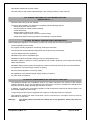
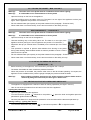
1
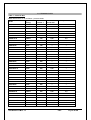
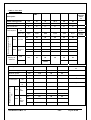
INSTRUCTION MANUAL
FOR INSTALLATION,
MAINTENANCE
AND USE
GAS KETTLES
“PM.G…A”
2800041
2800111
2800051
2800071
2800081
2800121
2800141
2800151
Cat. II2H3+
- 0085– AU0433
01.11.2003
25.06.2004
18.09.07
05
06
07
Cap.3.2.1
Pag.20
Tutti
Tutti
Tutti
Punto
Modify instruction
manual
Modify instruction
manual
Modify instruction
manual
Modify instruction
manual
Modificato libretto
Modificato libretto
Modificato libretto
Modificato libretto
Gas Kettles PM.G…A
- GB -
Type of correction
Natura della
correzione
Instruction manual for installation, maintenance and use
01.09.2000
04
Nr.
Data di
Revis. revisione
Page 2 di 26
Veränderfe
Handbuch
Veränderfe
Handbuch
Veränderfe
Handbuch
Veränderfe
Handbuch
Verbesserungsart
Storia delle revisioni
MANUALE D’ISTRUZIONE
Modifiè manuel
d’iinstallation
Modifiè manuel
d’iinstallation
Modifiè manuel
d’iinstallation
Modifiè manuel
d’iinstallation
Type de correction
Codice
G.A.
Budel
Budel
Budel
Firma
Visto
PM.G…A
INDEX
Part 1: General reminders and notes
1.1.
1.2.
1.3.
1.3.1.
1.3.2.
1.4.
1.5.
General reminders
Technical data
Construction
Special features for pressure kettles (Models PM…… A)
Special features for indirect kettles (Models PM.IG… .)
Laws, technical prescriptions and directives
Special requirements for the installation site
5
6
9
9
10
10
10
Part 2: Positioning, installation and maintenance
2.1.
2.2.
2.2.1.
2.2.2.
2.3.
2.3.1.
2.3.2.
2.4.
2.5.
2.5.1.
2.5.2.
2.5.3.
2.6.
2.6.1.
Positioning
Installation
Connection to waterworks
Gas connection procedures
Checking the operation of the gas system
Control of the gas inlet pressure
Control of primary air flow
Commissioning and testing
Conversion to other types of gas
Replacement of injectors for main burners
Replacement of injectors for pilot burner
Minimum output adjustment
Maintenance of the appliance
Possible failures and their elimination
11
11
11
11
12
12
12
13
13
13
13
14
14
14
Part 3: Use and cleaning
3.1.
3.2.
3.2.1.
3.2.2.
3.2.3.
3.3.
3.3.1.
3.4.
3.5.
3.6.
Warnings and hints for user
Instructions for use
Filling the jacket
Use of pressure kettle lid (Models PM…… A)
Switch on, start of cooking and switch off
Cleaning and care of the appliance
Daily cleaning
Special procedures in case of long inactivity
Special procedures in case of failures
How to proceed, if …
Instruction manual for installation, maintenance and use
Gas Kettles PM.G…A
15
15
15
16
16
16
16
17
17
17
- GB -
Page 3 di 26
Part 4: Figures and details
4.1.
4.2.
4.3.
4.4.
4.5.
4.6.
4.7.
4.8.
Size of appliance and position of connections
Measuring the inlet pressure
Gas cock
Pilot burner
Main burner
Primary air regulation
Controls
Relief valve (only pressure kettles)
Instruction manual for installation, maintenance and use
Gas Kettles PM.G…A
18
21
22
23
23
24
25
25
- GB -
Page 4 di 26
1.1. GENERAL REMINDERS
−
Read the warnings contained in this manual carefully as they provide important information concerning
safety during the installation, use and maintenance of the appliance.
−
Keep these instructions carefully!
−
Only personnel trained for its specific use should use the equipment.
−
Keep the appliance under control during use.
−
The appliance should be used only for the purpose for which it has been specifically designed; other
uses are improper and hence dangerous.
−
During operation surfaces can become hot and require special operation.
−
Unplug the appliance in case of failures or improper operation.
−
Apply exclusively to a service centre for repairs or maintenance.
−
All important information about the appliance required for technical service is contained in the technical
data plate (see figure “Size of appliance and position of connections”).
−
In the event of technical assistance being required, the trouble must be described in as much detail as
possible, so that a service technician will be able to understand the nature of the problem.
−
Gloves should be worn to protect the hands during installation and maintenance operations.
Warning! : Follow the fire prevention regulations very carefully.
Instruction manual for installation, maintenance and use
Gas Kettles PM.G…A
- GB -
Page 5 di 26
1.2. TECNICAL DATA
Table 1 – General data
Note: Models with "A" as end letter = pressure kettle
PM8DG100
Type of
heating:
Direct
PM9DG100
Direct
100
--
--
PM8DG100 A
Direct
100
0,05
--
PM9DG100 A
Direct
100
0,05
--
PM8IG100
Indirect
100
--
0,5
PM9IG100
Indirect
100
--
0,5
PM8IG100 A
Indirect
100
0,05
0,5
PM9IG100 A
Indirect
100
0,05
0,5
PM8DG150
Direct
140
--
--
PM9DG150
Direct
140
--
--
PM8DG150 A
Direct
140
0,05
--
PM9DG150 A
Direct
140
0,05
--
PM8IG150
Indirect
135
--
0,5
PM9IG150
Indirect
135
--
0,5
PM8IG150 A
Indirect
135
0,05
0,5
PM9IG150 A
Indirect
135
0,05
0,5
PM9DG200
Direct
200
--
--
PM9DG200 A
Direct
200
0,05
--
PM1DG200
Direct
200
--
--
PM1DG200 A
Direct
200
0,05
--
PM1IG200
Indirect
200
--
0,5
PM1IG200 A
Indirect
200
0,05
0,5
PM1DG300
Direct
300
--
--
PM1DG300 A
Direct
300
0,05
--
PM1IG300
Indirect
300
--
0,5
PM1IG 300 A
Indirect
300
0,05
0,5
PM1DG500
Direct
500
--
--
PM1DG500 A
Direct
500
0,05
--
PM1IG500
Indirect
500
--
0,5
PM1IG500 A
Indirect
500
0,05
0,5
PM9DG170GN
Direct
170
--
--
PM9IG170GN
Indirect
170
--
0,5
PM9DG270GN
Direct
270
--
--
PM9IG270GN
Indirect
270
--
0,5
PM9DG370GN
Direct
370
--
--
PM9IG370GN
Indirect
370
--
0,5
Model
Vat usable
volume: I
100
Instruction manual for installation, maintenance and use
Gas Kettles PM.G…A
Pressure in
the vat: bar
--
Jacket pressure: bar
--
- GB -
Page 6 di 26
Table 2 – Sizes (see figure “Size of appliance and position of connections”)
Specifications
Description
Models
Unit of
measure
ment
PM8…
PM9…
PM9DG200
PM1.G200
PM1.G300
PM1.G500
Width (A)
mm
800
900
900
1000
1150
1150
Depth (B)
mm
900
900
1150
1300
1300
Height (C)
mm
900
950
900
900
1050
Vat diameter
mm
600
600
750
900
900
Specifications
Description
Models
Unit of
measurement
PM9.G170GN
PM9.G270GN
PM9.G370GN
Width (A)
mm
1000
1400
1800
Depth (B)
mm
900
900
900
Height (C)
mm
900
900
900
Vat diameter
mm
700X550
1100X550
1500X550
Table 3 – General water data
Specifications
Description
Models
Unit of
measurement
PM8…. .
PM9…. .
PM1.G200 / 300 / 500
PM9DG200
PM9…GN
Cold water connection
mm
10
½”
Hot water connection
mm
10
½”
Water pressure
kPa
50 – 300
Table 4 – Minimum output setting
G 20 – 20 mbar
G 30 – 28-30/37 mbar
PM8… ./PM9…. .
PM1.G200
PM1.G300
PM1.G500
2,5 mbar
8,6 mbar
5,6 mbar
5 mbar
3 mbar
12 mbar
8,5 mbar
7,25 mbar
PM9.G170GN
PM9.G270GN
PM9.G370GN
G 20 – 20 mbar
7,5 mbar
4 mbar
3,5 mbar
G 30 – 28-30/37 mbar
11,6 mbar
5,5 mbar
10,5 mbar
Instruction manual for installation, maintenance and use
Gas Kettles PM.G…A
- GB -
Page 7 di 26
Table 5 – Gas data
Description
PM8…. .
PM9…. .
PM9DG200
PM1.G200
PM1.G300 PM1.G500
Lower
calorific
value
Hi
Rated heating power
kW
21
32
34.5
48
65
Minimum power
kW
7
15
22.5
26.5
33
Gas connection
R”
½”
½”
½”
½”
½”
G20 –
2H
m3/h
2,22
3,38
3,65
5,07
6,88
kWh/m3
9,45
G30 – 3+
Kg/h
1,65
2,52
2,72
3,78
5,13
kWh/kg
12,68
40
40
40
40
40
Maximum
3 X 205
4 X 225
4 X 225
4 X 280
4 X 310
Minimum
ADJUST
.
ADJUST.
ADJUST.
ADJUST.
ADJUST.
20
25
25
25
25
Maximum
3 X 135
4 X 145
4 X 150
4 X 185
4 X 195
Minimum
ADJUST
.
ADJUST.
ADJUST.
ADJUST.
ADJUST.
30
23
30
10
30
OPEN
OPEN
Nozzles diameter in 1/100
mm
Consumption
Pilot
G20
20 mbar
Pilot
G30
28-30/37
mbar
Primary air
distance
G20
mm
G30
OPEN
PM9.G170GN
Description
PM9.G270GN PM9.G370GN
Lower calorific value
Hi
Rated heating power
kW
30
44
49
Minimum power
kW
17,8
20
24
Gas connection
R”
½”
½”
½”
G20 –
2H
3
m /h
3,17
4,65
5,18
kWh/m3 9,45
G30 –
3+
Kg/h
2,36
3,47
3,86
kWh/kg 12,68
40
40
40
Maximu
m
6 X 175
10 X 170
14 x 150
Minimum
ADJUST.
ADJUST.
ADJUST.
25
25
25
Maximu
m
6 X 115
10 X 110
14 x 80
Minimum
ADJUST.
ADJUST.
ADJUST.
Nozzles diameter in 1/100
mm
Consumption
Pilot
G20
20
mbar
Pilot
G30
2830/37
mbar
Instruction manual for installation, maintenance and use
Gas Kettles PM.G…A
- GB -
Page 8 di 26
Primary air
distance
G20
mm
G30
1
10
30
25
18
OPEN
Table 6 – Gas inlet pressure
Table 6a
Nominal main pressure for the different
types of gas
Table 6b
Operation permissible if pressure is in the
range:
Table 6c
Operation non permissible if pressure is
lower than:
Table 6d
Operation non permissible if pressure is
higher than:
Gas family 2 – Natural
20 mbar
Gas family 3 –LPG
28-30/37 mbar
Gas family 2 – Natural
da 17 a 25 mbar
Gas family 3 –LPG
da 20/25 a 35/45 mbar
17 mbar
Gas family 2 – Natural
Gas family 3 –LPG
20/25 mbar
25 mbar
Gas family 2 – Natural
Gas family 3 –LPG
35/45mbar
1.3. CONSTRUCTION
−
Main structure in steel with 4 adjustable height feet.
−
Panels in stainless steel AISI 304, thickness 10-12/10.
−
Cooking vat in stainless steel AISI 316, thickness 20/10.
−
Lid in stainless steel, hinged and spring balanced in all opening positions.
−
Chrome-plated brass drainage tap.
−
Vat heating controlled by means of high efficiency stainless steel tubular burners resistant to mechanical
and thermal stress.
−
The gas supplied to the burner is adjusted by a cock.
−
The appliance has a pilot burner with fixed injector, besides piezoelectric ignition.
−
The safety of the appliance is ensured by a thermocouple that cuts off the gas flow if the pilot burner
should turn off for any reason.
−
The cold/hot water connection is 10 mm. (Mod. 100/150lt.)
−
The cold/hot water connection is ½”. (Mod. 200/300/500/170/270/370lt.)
−
The appliance is equipped with a mixer tap.
1.3.1. SPECIAL FEATURES FOR PRESSURE KETTLES
(MODELS PM…… A)
−
Stainless steel lid with heat-resistant silicone gasket.
Instruction manual for installation, maintenance and use
Gas Kettles PM.G…A
- GB -
Page 9 di 26
−
Hermetically sealed with 4 screw clamps.
−
The relief valve for the pressure that develops in the cooking chamber is set at 0.05 bar.
1.3.2. SPECIAL FEATURES ONLY FOR INDIRECT KETTLES
(MODELS PM.IG… .)
−
Stainless steel cooking vat and chamber.
−
To ensure safe operation, the appliance is equipped with the following devices:
− Steam safety valve set at 0.5 bar;
− Pressure gauge for steam pressure reading;
− Jacket steam trap;
− Steam pressure switch set at 0.5 bar;
− Jacket water supply with level control by means of taps.
−
Safety thermostat to interrupt operation automatically in case of failures.
1.4. LAWS, TECHNICAL PRESCRIPTIONS AND DIRECTIVES
When installing the appliance it is necessary to follow and comply with the following regulations:
−
current regulations on the matter;
−
any hygienic-sanitary regulations concerning cooking environments;
−
municipal and/or territorial building regulations and fire prevention prescriptions;
−
current accident prevention guidelines;
−
standards for the use of combustible gas;
−
standards for gas-fired systems utilizing on-tap or liquid petroleum gas;
−
standards relating to gas-fired cooking appliances and similar equipment used large-scale catering.
Safety requirements;
−
standards relating to gas systems for appliances used in professional kitchens and communal facilities;
−
the regulations of the gas supply company or agency;
−
electricity board regulations concerning safety;
−
the regulations of the electrical power supply company or agency;
−
any other local prescriptions.
1.5. SPECIAL REQUIREMENTS FOR THE INSTALLATION SITE
−
The appliance belongs to the installation class A1 (no direct connection of a chimney of flue exhaust
system is required), so it is very important for the environment in which it is installed to be well-aired and
provided with all the safety openings prescribed for its power.
−
In addition, it is good policy to locate the appliance under an extractor hood so that cooking vapours can
be removed rapidly and continuously.
−
The gas supply system must be equipped with a rapid on off tap approved for the purpose.
−
This appliance requires two water connections: one for hot and one for cold water. Each line must be
fitted with an on-off valve.
Warning! :
The shutoff valves must both be located near to the appliance, within easy reach for
the user.
Instruction manual for installation, maintenance and use
Gas Kettles PM.G…A
- GB -
Page 10 di 26
2.1. POSITIONING
−
Remove all the packaging and check that the appliance is in perfect conditions. In case of visible
damage, do not connect the appliance and notify the sales point immediately.
−
Remove the PVC protection from the panels.
−
Dispose of packaging according to regulations. Generally material is divided according to composition
and should be delivered to the waste disposal service.
−
Maintain a distance of 5 cm between the back (chimney) of the appliance and the wall. There are no
particular prescriptions regarding side distances from other appliances or walls, however it is advisable
to leave enough space in case of maintenance and/or repairs. It is advisable to fit a suitable heat
insulation if the appliance is in direct contact with inflammable walls.
−
The appliance must stand level. Small differences in level can be eliminated by screwing or unscrewing
the adjustable feet: A significantly uneven or sloping stance can affect the operation of the appliance
adversely.
2.2. INSTALLATION
Warning! : Only qualified technicians must perform the installation, maintenance and test of the
appliance.
Warning! :
Before connecting any parts of the appliance to supplies, make sure that the latter is
equivalent the requirements stated in the technical data plate, if the appliance has
been designed for these supplies.
2.2.1. CONNECTION TO WATERWORKS
−
Water inlet pressure must be between 50 and 300 kPa, otherwise install a pressure regulator on the line
before the appliance.
−
Install a cut-off valve for each supply on the line before the appliance.
−
Water connections to 10 mm are fitted in the lower part on the left-hand side of the appliance.
−
Make connections according to regulations currently in force.
2.2.2. GAS CONNECTION PROCEDURES
−
The choice of the gas piping depends on the diameter required for the type of gas, appliance and
installation and should be performed in conformity with current regulations.
−
The gas feed plant can either be fixed or be disconnected; if flexible pipes are employed they must be
made from stainless material and not be affected by corrosion.
−
If sealing materials are used for connections, they must be certified and approved for the purpose.
−
The gas fitting is located on the lower right side of the appliance
−
Once the appliance has been connected, carry out a leakage test on all the fittings connecting the
appliance to the plant. It is advisable to use a leakage spray, otherwise treat the parts with a foam that
does not produce corrosion; no bubbles should develop. Carry out the leakage test also on the rapid cutoff valve.
Warning! :
Flames are strictly prohibited for leakage tests!
Instruction manual for installation, maintenance and use
Gas Kettles PM.G…A
- GB -
Page 11 di 26
2.3. CHECKING THE OPERATION OF THE GAS SYSTEM
−
Check that the appliance has been prepared (category and type of gas) equivalent to the family of gas
available on site. If not, it is necessary to convert the appliance to whatever is available. See the
paragraph “Conversion to other types of gas”.
−
The appliance must be used with the correct injectors for its thermal power rating (See table 5 in the
“Technical data”).
−
The operation of the appliance with its heating capacity depends on the inlet pressure and the calorific
power of the gas.
−
The pressure range (inlet pressure) within which the appliance is allowed to operated is stated in table 6b
“Inlet pressure” of the paragraph “Technical Data”. The appliance shall not be operated out of the given
pressure range. If pressure should differ from the figures stated in table 6b, advise the gas board or the
company which has installed the system.
−
The lower calorific value of the gas can be checked with the supply company or agency, and should
comply with the information given in table 5 “Gas data” in the “Technical data” heading.
2.3.1. CONTROL OF THE GAS INLET PRESSURE
−
The feed pressure is measured using a liquid pressure gauge ( e.g. a U-shaped pressure gauge,
minimum definition 0.1 mbar). The supply pressure can be measured directly at the inlet pressure
intake on the gas feed pipe. The inlet pressure intake can be reached by opening the lower front panel
once the two side screws have been removed. (See figure “Measuring the inlet pressure ”).
−
Before connecting the manometer, the screw of the pressure port must be loosened.
−
Connect the U-shaped pressure gauge while the appliance is operating to measure pressure.
−
The pressure reading on the gauge should be in the admitted pressure range stated in table 6b “Inlet
pressures” of paragraph “Technical data”.
− If pressure figures should not be correct, apply to the gas board or the company which has installed the
system.
−
Having read the pressure, re-tighten the screw carefully.
Warning!
The sealed adjuster screws on the gas solenoid valve must not be tampered with,
otherwise any guarantee rights shall be forfeited immediately.
2.3.2. CONTROL OF PRIMARY AIR FLOW
−
Primary air can be considered correctly adjusted if no flame lift is ensured when the burner is cold and
the injector lights when the burner is hot.
−
The distance “H” (see figure “Primary air regulation”) recommended for primary air adjustment is stated
in table 5 in the “Technical data”.
Instruction manual for installation, maintenance and use
Gas Kettles PM.G…A
- GB -
Page 12 di 26
2.4. COMMISSIONING AND TESTING
−
Once all the connections have been made, the appliance and the overall installation must be checked
following the directions given in this manual.
−
Check in particular:
−
−
−
−
−
that the protective film has been removed from the external surfaces;
that connections have been made in accordance with the requirements and directions indicated in
this manual;
that all safety requirements in current standards, statutory regulations and directives have been met;
that the water and gas connections are leak-free;
that the electrical connection has been performed according to standards.
−
Now the appliance can be ignited following the instructions for use and controlling the following points:
- progressive ignition of the burner;
- even flames;
- flame security: check these points at both minimum and maximum output.
−
Check that the flue gas exhaust is not clogged and that they are expelled without any hindrance.
−
The test report must be completed in full and submitted to the customer who should then sign in
acceptance. With effect from this moment, the appliance is covered by the manufacturer’s warranty.
2.5. CONVERSION TO OTHER TYPES OF GAS
−
To convert the appliance for use with another type of gas, the injectors on the main burners and on the
pilot burner need to be replaced. (See table 5 and figure “Main burner”).
-
All the injectors needed for the different types of gas are contained in a bag supplied with the appliance.
-
The supply pressure and the manual setting of minimum output should also be checked. (See table 4 –
Minimum output setting).
2.5.1. REPLACEMENT OF INJECTORS FOR MAIN BURNERS
–
The injectors can be reached by removing the lower front panel, once the two side screws have been
unloosed.
–
Disconnect the tube with the injectors, unloose the screws and remove.
–
Use a fixed wrench SW11 to unscrew the injector and replace it with a suitable one.
–
Re-install the primary air regulation bracket at the distance “H” as shown in table 5, see also “Primary air
regulation”.
2.5.2. REPLACEMENT OF INJECTORS FOR PILOT BURNER
–
The injector of the pilot burner can be reached by removing the lower front panel. Remove the side and
lower screws.
–
The pilot burner is in the front of the combustion chamber.
–
Unloose the screw and replace the injector with an appropriate one.
Instruction manual for installation, maintenance and use
Gas Kettles PM.G…A
- GB -
Page 13 di 26
2.5.3. MINIMUM OUTPUT ADJUSTMENT
–
Once the appliance has been switched on, set the cock knob on the minimum position.
−
Remove the cock knob that will reveal a small hole on the panel of the appliance.
Turn the minimum adjustment screw on the cock with a screwdriver through the hole on the panel.
Warning!
Measure the minimum output pressure directly at the output pressure connection on
the injector tube (see figure “Measuring gas pressure”)
−
Set the output pressure of the gas cock according to the figures stated in table 4 - Minimum output
setting).
−
After setting, seal the adjustment screw!
Warning!
After each conversion, it is necessary to check tightness and operation!
2.6. MAINTENANCE OF THE APPLIANCE
Warning! :
−
All maintenance operations shall only be performed by a technically qualified service
centre!
To ensure correct and safe operation, the appliance must be inspected and serviced at least once a year
only. Maintenance includes also to control the components and tear of pipes, feeding pipes etc..
It is advisable to replace worn components during maintenance operations to avoid the need for other
maintenance calls and unexpected failures.
−
It is also advisable to apply for a maintenance contract with the customer.
2.6.1. POSSIBLE FAILURES AND THEIR ELIMINATION
Warning! :
Only technically qualified service centres can perform the operations described
below!
Warning! :
Before resetting the safety thermostat, it is always necessary to eliminate the
problem causing its activation (only for models with indirect heating)!
Problem and possible cause
Access to components and operation
Instruction manual for installation, maintenance and use
Gas Kettles PM.G…A
- GB -
Page 14 di 26
The content of the vat does not heat up:
−
the safety thermostat has been
activated.
Main burners
Remove the lower front panel.
The pilot burner is on but the main
burners do not light up:
−
loss of pressure in gas supply;
−
clogged injectors on main burners.
Safety thermostat
The safety thermostat can be reached by removing the lower
front panel once the two side screws have been unloosed.
Pilot burner
Remove the lower front panel. The pilot burner is in the front of
the combustion chamber.
The pilot burner does not light up:
Ignition plug and thermocouple
Remove the lower front panel.
−
clogged injectors on pilot burner;
−
faulty ignition plug;
−
check the cable of the ignition plug.
The pilot burner does not remain lighted:
−
faulty thermocouple;
−
partially
burner;
−
faulty cock magnet.
clogged
injector
on
pilot
3.1. WARNINGS AND HINTS FOR USER
−
This manual contains all the instructions required for a proper and safe use of our appliances.
Keep the manual in a safe place for future consultation!
−
This appliance is for catering use, hence they must be used only by trained kitchen staff.
−
The appliance must always be kept under control during use.
Warning! :
The manufacturer shall not be held responsible for injuries or damage due to the noncompliance with safety rules or an improper use of the appliance by the operator.
−
Some improper operating conditions may even be caused by an improper use of the appliance,
therefore it is important to train personnel properly.
−
All the installation and maintenance operations must be performed by fitters who are members of
an official register.
−
Respect the periods required for maintenance. With this is mind, customers are recommended to sign a
service agreement.
−
In case of failures concerning the appliance, all outputs (gas and water) must be cut off instantly.
−
In case of recurrent failures contact a service technician.
3.2. INSTRUCTIONS FOR USE
−
Before cooking with the appliance for the first time wash the interior of the cooking vat thoroughly.
Warning! :
Fill the cooking vat up to a maximum of 40 mm under the overflow border, according
to the maximum level mark, including the food to be cooked.
Instruction manual for installation, maintenance and use
Gas Kettles PM.G…A
- GB -
Page 15 di 26
3.2.1. FILLING THE JACKET – MOD. 100-150LT.
Warning! :
The water level in the jacket must be checked each time before lighting.
Warning! :
It is advisable to use softened water to fill the jacket!
−
Open the level tap on the front of the appliance.
−
Unscrew the filling cap on the safety valve unit. The latter is on the right of the appliance surface (see
figure “Size of appliance and position of connections ”).
−
Fill with softened water (the capacity of the jacket is stated in the paragraph “Technical data”).
−
When water flows out of the level tap, close it and screw back on the safety unit cap.
MOD. 200/300/500 LT. – 170/270/370LT.
Warning! :
The water level in the jacket must be checked each time before lighting.
Warning! :
It is advisable to use softened water to fill the jacket!
−
Open the level tap on the front of the appliance.
−
Unscrew the filling cap on the safety valve unit. The latter is on the right of the
appliance surface (see figure “Size of appliance and position of connections ”).
−
Reposition the tap (an external hole is available) on the external pin of the relief
valve.
−
This operation is required to prevent water bubbles from forming in the jacket
during water loading. Water bubbles would not make it possible to reach a correct
water level in the jacket.
−
Fill with softened water (the capacity of the jacket is stated in the paragraph “Technical data”).
−
When water flows out of the level tap, close it and screw back on the safety unit cap.
3.2.2. USE OF THE PRESSURE KETTLE LID
(MODELS PM…… A)
−
Before switching on the appliance, close the lid firmly and tighten the 4 clamps.
–
The interior of the kettle can reach a maximum pressure of 0.05 bar.
−
When this pressure is exceeded, the pressure relief valve on the lid will start operating. On request, the
appliance is also available with a pressure gauge to display the pressure inside the kettle.
Warning! :
After cooking and before opening the lid, all the pressure inside the kettle must be
released by lifting the relief valve (see also figure “Relief valve”.
3.2.3. SWITCH ON, START OF COOKING AND SWITCH OFF
−
The appliance is equipped with a selector to start all cooking operations (see figure “Cotrols”).
−
Here is a list of the procedures for a safe and correct use of the appliance.
Lighting the pilot burner:
−
Open the gas cock before the appliance.
−
Turn the knob from position “” leftwards to the position “”, press the knob and together press the
piezoelectric ignition button repeatedly..
−
Once the pilot flame is on, keep the knob pressed for a few seconds until the thermocouple heats up.
Starting cooking – igniting main burner:
−
Turn the knob leftwards to the position “
“or until minimum position “
Instruction manual for installation, maintenance and use
Gas Kettles PM.G…A
” to light the burner.
- GB -
Page 16 di 26
−
Generally cooking is started by setting the knob on the maximum heating position and once the vat has
reached cooking temperature, the knob is turned to the minimum position to maintain the cooking
temperature.
End of cooking – turning off main burner and pilot burner:
−
Turn the knob rightwards until position “” to turn off the main burner; only the pilot flame will be lighted.
Turn the knob again until position “” to turn off the pilot burner. (See also figure “Controls”).
3.3. CLEANING AND CARE OF THE APPLIANCE
−
Do not use aggressive substances or abrasive detergents when cleaning the stainless steel
components.
−
Avoid using metal pads of the steel parts as they may cause rust. For the same reason avoid contact
with materials containing iron.
−
Do not use sandpaper or abrasive paper for cleaning; in special cases use a powder pumice stone.
−
In case of particularly resistant dirt, it is advisable to use abrasive sponges (e.g. Scotch-Brite).
−
It is advisable to clean the appliance only once it has cooled down.
3.3.1. DAILY CLEANING
Warning! :
When cleaning the appliance never use direct jets of water to prevent infiltration of
the liquid and damage to components.
−
Clean the cooking vat with water and a detergent, rinse thoroughly and dry well with a soft cloth.
−
External surfaces should be washed down using a sponge, and hot water with a suitable proprietary
cleaner addend.
−
Rinse always thoroughly and dry with a soft cloth.
Note for pressure kettles:
−
Do not use detergents containing high percentages of ammonia and sodium to clean the lid gasket, as
these substances may cause damage and quickly affect the tightness of the gasket.
3.4. SPECIAL PROCEDURES IN CASE OF PROLONGED INACTIVITY
−
If the appliance is to stand idle for any length of time (e.g. holidays or seasonal closing) it must be
cleaned thoroughly, leaving not traces of food or dirt.
−
Leave the lid open so that air can circulate inside the vat.
−
For added care after cleaning, the external surfaces can be protected by applying a proprietary metal
polish.
−
Be absolutely certain to shut off all utilities (gas and water).
−
Air the room appropriately.
3.5. SPECIAL PROCEDURES IN CASE OF FAILURES
−
If the appliance should not work properly during use, turn it off immediately and close or cut off all
supplies (gas and water).
−
Apply to a service centre for help.
Instruction manual for installation, maintenance and use
Gas Kettles PM.G…A
- GB -
Page 17 di 26
The manufacturer shall not be held responsible nor has any warranty commitments for damage
caused by non-compliance with prescriptions or by installation not in conformity with instructions.
The same applies in case of improper use or different application by the operator.
3.6. HOW TO PROCEED, IF …
Warning! :
Problems and failures may occur even when the appliance is used properly. Here is a
list of the mist probably situations and controls that the operator should perform to
avoid applying to a service centre unnecessarily.
If the problem is not solved after the necessary controls, turn off the appliance immediately,
cut off any supplies and apply to a service centre.
… the vat contents do not heat −
up:
−
−
check that there is gas in the mains and that the cock is open;
check that the main burners are on.
Otherwise turn off the unit and apply to a service centre, as the
safety thermostat may have been activated because of an excess
of temperature in the cooking vat. This occurs aspecially wehn the
appliance is started and the vat and/or jacket is/are empty or when
the appliance needs servicing because the burners are dirty and
clogged.
4.1. SIZE OF APPLIANCE AND POSITION OF CONNECTIONS
Models PM8.G… / PM9.G… .
LEGEND:
T - Technical data plate
G - Gas connection R ½” in conformity with ISO 7-1
Instruction manual for installation, maintenance and use
Gas Kettles PM.G…A
ABS-
Hot water connection 10 mm
Cold water connection 10 mm
Overflow
- GB -
Page 18 di 26
A
C
A
B
G
B
125
S
125
Instruction manual for installation, maintenance and use
Gas Kettles PM.G…A
50
40
35
580
380
- GB -
Page 19 di 26
Models PM1IG200 / PM1IG300 / PM1IG500
LEGEND:
AB-
T - Technical data plate
G - Gas connection R 1/2” in conformity with ISO 7-1
Hot water connection ½”
Cold water connection ½”
A
C
A- B
B
95
50
A
B
G
90
360
280
Models PM9.G…GN
Instruction manual for installation, maintenance and use
Gas Kettles PM.G…A
- GB -
Page 20 di 26
LEGEND:
G - Gas connection R 1/2” in conformity with ISO 7-1
AB-
Hot water connection ½”
Cold water connection ½”
C
A
40
A
B
B
510
380
460
G
Instruction manual for installation, maintenance and use
Gas Kettles PM.G…A
- GB -
Page 21 di 26
4.2. MEASURING THE INLET PRESSURE
LEGEND:
A
B
Inlet pressure intake
Outlet pressure intake
A
B
Instruction manual for installation, maintenance and use
Gas Kettles PM.G…A
- GB -
Page 22 di 26
4.3. GAS COCK
LEGEND:
A
B
C
D
Thermocouple nut
Gas output
Outlet pressure intake
Inlet pressure intake
E
F
G
H
Rated output adjustment screw
Gas inlet
Gas connection for pilot burner
Minimum output adjustment screw
E
B
C
H
A
G
D
F
Instruction manual for installation, maintenance and use
Gas Kettles PM.G…A
- GB -
Page 23 di 26
4.4. PILOT BURNER
LEGEND:
A
B
C
Thermocouple
Pilot burner
Ignition plug
D
E
Injector
Tightness screw
4.5. MAIN BURNER
LEGEND:
A
B
Burner
Injector
C
Injector pipe
B
A
Instruction manual for installation, maintenance and use
Gas Kettles PM.G…A
C
- GB -
Page 24 di 26
4.6. PRIMARY AIR REGULATION
H
Instruction manual for installation, maintenance and use
Gas Kettles PM.G…A
- GB -
Page 25 di 26
4.7. CONTROLS
LEGEND:
A
Knob
C
OFF position
D
E
F
C
F
Minimum position
Maximum position
Pilot flame position
D
E
A
4.8. RELIEF VALVE (ONLY PRESSURE KETTLES)
LEGEND:
Valve in operating position
Instruction manual for installation, maintenance and use
Gas Kettles PM.G…A
Valve in open position
- GB -
Page 26 di 26