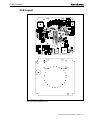
1
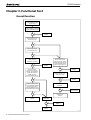
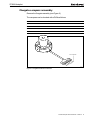
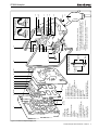
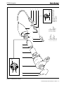
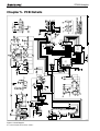
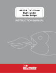
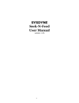
D296
ST3000 Autopilot
Z155, ST3000 Autopilot
Service Manual
Warning
CE Marking of Equipment/Replacement Parts
If the Autohelm equipment under repair, test, calibration, installation or setting to work carries the European CE mark,
only parts and components supplied or approved for such use by Raytheon should be used in order to maintain
compliance with the relevant CE requirements.
Incorporation, use or attachment, by any means, of parts or components not supplied for or not approved for such use by
Raytheon or, if supplied or approved for use by Raytheon, not properly fitted in accordance with instructions published,
provided or recommended by Raytheon, may cause the equipment to malfunction and, in particular, to become unsafe or
to no longer meet the relevant CE requirements. In these circumstances, Raytheon Marine Europe Ltd excludes liability
to the fullest extent permissible in law for any loss or damage including any liability for its contribution to such loss or
damage by its negligent acts or omissions .
ST3000 Autopilot Service Manual 83004-2 1
ST3000 Autopilot
Chapter 1. Before Dismantling
Before dismantling the autohelm ST3000 check the phase of the autopilot (If
PCB condition allows) by driving the pilot, in standby mode, with the course
change keys.
+10 key
–10 key
Aft facing actuator
Clockwise actuator rotation
Anticlockwise actuator rotation
Forward facing actuator
Anticlockwise actuator rotation
Clockwise actuator rotation
All new spares PCBs are factory set to operate the pilot with the drive unit
facing aft. A replacement PCB for an installation with the drive unit facing
forward requires resetting.
To reset the operating sense press the +1° and -1° course keys together for
5 seconds.
The unit beeps for 10 seconds to confirm changeover and the display shows
the new setting, either ‘Port’ (actuator sprocket facing forward) or ‘Starb’
(actuator sprocket facing aft’).
The autopilot may be calibrated t to suit a particular vessel. Note the
calibration settings and set up the new PCB if required.
If the spares PCB contains software of a higher issue than before then the
relevant Operating Supplement must be supplied when the equipment is
returned to the customer.
Note: Replacement PCBs require setting up to ST3000.
Refer to Autopilot type selection on page 3 for instructions.
2 ST3000 Autopilot Service Manual 83004-2
ST3000 Autopilot
Chapter 2. Special Functions
Display test
A display test feature included in ST3000 software checks that the display
assembly has been re-fitted correctly. Display test is switched on by
momentarily pressing the -1° and +10° keys together
The display scrolls all four characters through from 0 to 9 and then displays
each annotation. This sequence continues until either the ‘Standby’ or ‘Auto’
key is pressed or the unit is powered down.
Autopilot type selection
The Autohelm range of cockpit pilots all contain the same software but each
pilot runs a different program. This is contained within the same chip but
needs to be selected as follows:
1. Press the -10° and +1° degree keys until the display shows the pilot type
number (Approximately 5 seconds)
2. Press the -10° and +1° degree keys again until the display flashes the
pilot type number (Approximately 5 seconds)
3. Select the correct pilot type using the +1° and -1° degree keys
4. Save the setting by pressing the -10° and +1° degree keys until the
normal Standby display appears (Approximately 2 seconds)
Note: Changing Autopilot type will clear all calibration settings.
Display of software code
The software code of the pilot can be displayed as follows:
1. Switch the pilot to standby mode
2. Press the Standby key until the display shows P followed by a number.
(Approximately 10 seconds)
The number indicates the version of software fitted, e.g. P 0 6 indicates
Version 6 software
Calibration lockout
To stop access to compass linearisation and calibration functions on the
ST3000 autopilot:
1. Press the -1° and Standby keys for 10 seconds until the displayshows
CAL ON (or CAL OFF)
2. Toggle between CAL ON and CAL OFF using the -1° and +1° keys
3. Store the selected setting by pressing the -1° and Standby keys for 10
seconds, when the control head returns to normal operation.
Any attempt to linearise the compass or enter calibration when the lockout
function is enabled will result in the display showing Cal Off. In this condition
the user cannot change any settings.
ST3000 Autopilot Service Manual 83004-2 3
ST3000 Autopilot
Chapter 3. Functional Test
Overall function
Connect actuator to
Control Head and apply
power to unit
Unit beeps, and shows 3000
and then displays a magnetic
heading, with flashing 'C'
OK
No
Change PCB.
Restart.
Yes
Press & Hold +10 key.
Check motor runs.
OK
No
Yes
Press & Hold -10 key.
Check actuator runs.
OK
No
Yes
Press AUTO and check
display shows 'A'
followed by a heading.
OK
No
Change PCB.
Restart.
Disconnect power and
remove drive module.
Disconnect motor spade
terminals and apply 10V DC
to motor terminals. Check
motor runs. (See Figure 3).
Yes
OK
Hold unit vertical.
Rotate it in clockwise
direction; check actuator
rotates anti-clockwise
(STBD set up) or
clockwise (PORT set up)
No
Change motor.
Restart.
Yes
Reverse 10V on motor.
Check motor runs.
No
OK
OK
No
Change motor.
Restart.
Yes
Yes
Hold unit vertical, rotate
it an anti-clockwise direction;
check actuator rotates
clockwise (STBD set up) or
anti-clockwise (PORT set up)
Check motor connections
and wires.
OK
No
Change faulty
item(s). Restart.
Yes
OK
No
Change PCB.
Restart.
Yes
Unit OK
Check fluxgate
(SECT 5.6)
OK
No
Change fluxgate.
Restart.
Yes
Change PCB.
Restart.
D4103-1
4 ST3000 Autopilot Service Manual 83004-2
ST3000 Autopilot
Fluxgate compass assembly
Remove the fluxgate assembly (see Figure 2).
The compass can be checked with a DVM as follows:
Connect meter across
Resistance
1 and 2
<10 ohms
3 and 5
< 5 ohms
3 and 4
< 5 ohms
1 and 3
Open circuit
No connection
1
2
3
4
5
D4104-1
Figure 1. Fluxgate electrical connections
ST3000 Autopilot Service Manual 83004-2 5
ST3000 Autopilot
Chapter 4. Disassembly/Assembly
SeaTalk Deck Plug
Pin carrier
Plug pin (x3)
Plug pin screw (x3)
Plug body
Screw (x2)
Metal sleeve (x3)
Blue wire
Brown wire
Cable assembly
(3016-104)
Assemble sleeve to wire.
Pinch sleeve with pliers. Insert
sleeve into plug pin and tighten
screw to retain. Cut off excess
metal sleeve to prevent short
circuit.
Repeat process for remaining
wires.
Yellow
wire
Cable
clamp
Cable
seal
Clamp
nut
D4107-1
Electrical connections
Wire colour
Description
Brown
+12V nominal supply
Blue
0V supply
ST3000 Autopilot Display Unit
Spare parts list
The item numbers refer to Figure 2: ST3000 Autopilot display unit.
Item
Spare Description
Part No.
Comments
–
Control Head
Q056
Complete head
LCD kit, including
LCD surround
LCD
Elastomer
Diffuser
Reflector
Locking wedge (x5)
Q053
4
5
6
7
8
27
9
PCB assembly
Q044
13
Fluxgate assembly
M022
30
SeaTalk deck plug assembly
D326
6 ST3000 Autopilot Service Manual 83004-2
LCD not included
29 (Note C)
4
5
6
7
2 (x6)
3 (x6)
28
1. Facia
(Note A)
2. Keypad (x6)
17. Fluxgate drive
3. Actuator (x6)
18. Fluxgate sense B
4. LCD surround
19. Fluxgate sense common
5. LCD
20. Fluxgate sense A
6. Elastomer connector
21. SeaTalk data (yellow)
7. Diffuser
22. Shield (screen - black sleeve)
8. Reflector
23. +12V supply (brown)
9. PCB
24. Ground (blue)
10. Seal
25. Motor (black)
11. Gimbol support (x2)
26. Motor (red)
12. Gimbol support screw (x2)
27. Wedge (x4)
13. Fluxgate assembly
28. Shim
14. Rear case
29. Spacer (early units only)
15. Case screw (x4)
30. SeaTalk deck plug assembly
16. Fluxgate ground
1
8
9
13
10
Display
bezel (4)
26
24
25
23
22
21
12 (x2) 11 (x2)
PCB (9)
Wedge (27)
Insert wedge (27) as shown
to secure display bezel leg
27 (x4)
Early units
Later units
16
30
15 (x4)
20
19
18
17
Note B
Important: The fluxgate loom in some
early units is wired differently.
Notes:
A. Keypads come bonded to facia on later units.
B. Ensure that the fluxgate loom is formed around the outside
of the rear case pillar. Failure to do so may result in the
gimbal action being impaired and the autopilot performance
degraded.
C. Early production units have a spacer (29) which is effectively
replaced by using 4 wedges (27) on later units.
14
D4101-1
ST3000 Autopilot
Figure 2: ST3000 Autopilot display unit
ST3000 Autopilot Service Manual 83004-2 7
ST3000 Autopilot
ST3000 Drive Actuator
Spare parts list
The item numbers refer to Figure 3: ST3000 Autopilot drive actuator.
Item
Spare Description
Part No.
Comments
–
ST3000 drive module
Q45
Complete drive
1
2
3
4
ST3000Gearbox/Drive
assembly, including
Pin
Clutch flange
Gearbox housing
Seal
2,1
Clutch flange & pin
H006
7
Motor
Q101
10
Pod
H001
Q102
Also part of Q102
Motor replacement
If the gearbox is noisy when the motor is replaced, remove motor, rotate
gearbox a small amount, and refit.
8 ST3000 Autopilot Service Manual 83004-2
1
2
Blue
(M2)
Brown
(M1)
3
Red
dot
4
5
6
7
16
1. Pin
2. Clutch flange
3. Gearbox housing
4. Seal
5. Flux ring
6. Location screw
7. Drive motor
8. Cap
9. Seal
17
8
9
10. Pod
11. Shroud
12. Grip
13. Seal
14. Location ring
15. Receptacle
16. Socket
17. 'O' ring
15
10
Brown
(M1)
Note:
Connect a 10v dc supply to the actuator
plug and measure the running current of
the drive unit.
< 2A - Drive healthy
> 2A - Drive faulty
Blue
(M2)
Pip
14
13
12
11
D4102-1
ST3000 Autopilot
Figure 3. ST3000 Drive Actuator
ST3000 Autopilot Service Manual 83004-2 9
ST3000 Autopilot
Chapter 5. PCB Details
D4108-1
Figure 4: Circuit Diagram
10 ST3000 Autopilot Service Manual 83004-2
ST3000 Autopilot
PCB Layout
Taken from Drawing No: 4155-010 Issue: J Date: 07.03.97
D4105-1
Figure 5: PCB Component Layout
ST3000 Autopilot Service Manual 83004-2 11
ST3000 Autopilot
PCB Component list
Taken from Drawing No: 4155-010 Issue: J Date: 07.03.97
Raytheon Marine Company
676 Island Pond Road
Manchester
New Hampshire 03109-5420
Tel: (001 603) 647 7530
Fax: (001 603) 634 4756
Raytheon Marine Europe Limited
Anchorage Park, Portsmouth
Hampshire PO3 5TD
Tel: (01705) 693611
Fax: (01705) 694642
http: //www.raytheon.com
12 ST3000 Autopilot Service Manual 83004-2
D4106-1