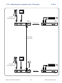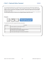
1
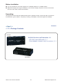
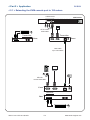
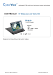
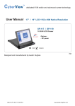
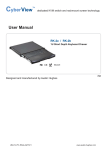
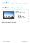
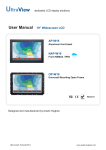
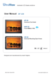
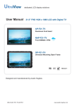
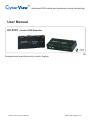
dedicated KVM switch and rackmount screen technology
User Manual
CV-S101
Combo KVM Extender
751
Designed and manufactured by Austin Hughes
UM-CV-751-CV-S101-Q215V1
www.austin-hughes.com
Legal Information
First English printing, October 2002
Information in this document has been carefully checked for accuracy; however, no guarantee is given to the correctness
of the contents. The information in this document is subject to change without notice. We are not liable for any injury or
loss that results from the use of this equipment.
Safety Instructions
Please read all of these instructions carefully before you use the device. Save this manual for
future reference.
■
■
■
■
■
■
■
■
■
■
■
Unplug equipment before cleaning. Don’t use liquid or spray detergent; use a moist cloth.
Keep equipment away from excessive humidity and heat. Preferably, keep it in an air-conditioned environment with
temperatures not exceeding 40º Celsius (104º Fahrenheit).
When installing, place the equipment on a sturdy, level surface to prevent it from accidentally falling and causing
damage to other equipment or injury to persons nearby.
When the equipment is in an open position, do not cover, block or in any way obstruct the gap between it and the
power supply. Proper air convection is necessary to keep it from overheating.
Arrange the equipment’s power cord in such a way that others won’t trip or fall over it.
If you are using a power cord that didn’t ship with the equipment, ensure that it is rated for the voltage and current
labeled on the equipment’s electrical ratings label. The voltage rating on the cord should be higher than the one listed
on the equipment’s ratings label.
Observe all precautions and warnings attached to the equipment.
If you don’t intend on using the equipment for a long time, disconnect it from the power outlet to prevent being
damaged by transient over-voltage.
Keep all liquids away from the equipment to minimize the risk of accidental spillage. Liquid spilled on to the power
supply or on other hardware may cause damage, fire or electrical shock.
Only qualified service personnel should open the chassis. Opening it yourself could damage the equipment and
invalidate its warranty.
If any part of the equipment becomes damaged or stops functioning, have it checked by qualified service personnel.
What the warranty does not cover
■
■
■
Any product, on which the serial number has been defaced, modified or removed.
Damage, deterioration or malfunction resulting from:
Accident, misuse, neglect, fire, water, lightning, or other acts of nature, unauthorized product modification, or
failure to follow instructions supplied with the product.
Repair or attempted repair by anyone not authorized by us.
Any damage of the product due to shipment.
Removal or installation of the product.
Causes external to the product, such as electric power fluctuation or failure.
Use of supplies or parts not meeting our specifications.
Normal wear and tear.
Any other causes which does not relate to a product defect.
Removal, installation, and set-up service charges.
□
□
□
□
□
□
□
□
Regulatory Notices Federal Communications Commission (FCC)
This equipment has been tested and found to comply with the limits for a Class B digital device, pursuant to Part 15 of
the FCC rules. These limits are designed to provide reasonable protection against harmful interference in a residential
installation.
Any changes or modifications made to this equipment may void the user’s authority to operate this equipment. This
equipment generates, uses, and can radiate radio frequency energy and, if not installed and used in accordance with the
instructions, may cause harmful interference to radio communications.
However, there is no guarantee that interference will not occur in a particular installation. If this equipment does cause
harmful interference to radio or television reception, which can be determined by turning the equipment off and on, the
user is encouraged to try to correct the interference by one or more of the following measures:
■ Re-position or relocate the receiving antenna.
■ Increase the separation between the equipment and receiver.
■ Connect the equipment into an outlet on a circuit different from that to which the receiver is connected.
UM-CV-751-CV-S101-Q215V1
www.austin-hughes.com
Contents
< Part. 1 > CV-S101
1.1
1.2
1.3
Package Contents
Transmitter
Receiver
P.1
P.2
P.3
< Part. 2 > Application
2.1
2.2
2.3
Extending the KVM console port to 150 meters
Extending the computer to KVM port to 150 meters
Extending the computer up to 150 meters
< Part. 3 > Keyboard Hotkey Command
UM-CV-751-CV-S101-Q215V1
P.4
P.5
P.6
P.7
www.austin-hughes.com
Before Installation
■ It is very important to mount the equipment in a suitable cabinet or on a stable surface.
■ Make sure the place has a good ventilation, is out of direct sunlight, away from sources of excessive
dust, dirt, heat, water, moisture and vibration.
Unpacking
The equipment comes with the standard parts shown in package content. Check and make sure they are
included and in good condition. If anything is missing, or damaged, contact the supplier immediately.
< Part 1 >
CV-S101
< 1.1 > Package Contents
Receiver
CV-S101 Receiver and Transmitter X 1
- CE-6 6ft Combo KVM cable X 1
- Power adapter w/ power cord ( for receiver ) X 1
Transmitter
UM-CV-751-CV-S101-Q215V1
P.1
www.austin-hughes.com
< 1.2 > Transmitter
CV-S101
Local
Computer
VGA
Remote I/O
Power
Front
Rear
KB Mouse
USB
Power Status
LED
LED
LED
Status
Power
Solid Red
Power is on ( from the local computer or power adapter )
No Light
There is no Power
Solid Blue
The connection to Receiver is active
Flashing Blue
Transmitter is sending or receiving data
No Light
No connection established
Status
Description
Transmitter Specification
Console Port
1 x DB-15 VGA, up to 1600 x 1200
2 x USB connector for KB & mouse
Remote I / O
1 x RJ-45, connect the receiver up to 150 meters via Cat5/6 cable
Local computer
1 x DB-15 combo KVM port
LED
Power ( red ) & Status ( blue )
Power
From attached local computer or optional 12V power adapter
Operation Temperature
0 ~ 55 °C
Storage Temperature
-20 ~ 60 °C
Humidity
0~80%, Non-Condensing
Dimension
157.8 x 70 x 30.6 mm
Weight
370g
Environmental
RoHS2 & REACH compliant
UM-CV-751-CV-S101-Q215V1
P.2
www.austin-hughes.com
< 1.3 > Receiver
CV-S101
Local
Computer
VGA
Remote I/O
Power
Front
Rear
KB Mouse
USB
Local Remote
Button Button
Button
Status
Local
Solid Blue
Local port is pressed & connected to the local PC
Blinking Blue
Local port is pressed & no PC signal is detected
No Light
The local port is not selected or the power is off
Solid Blue
Remote port is pressed & connected to the Transmitter
Rapid Flashing Blue
Remote port is pressed & auto-adjusting the signal
Moderate Flashing Blue
Remote port is pressed & no connection established
No Light
Remote port is not selected or the power is off
Remote
Description
Receiver Specification
Console Port
1 x DB-15 VGA, up to 1600 x 1200
2 x USB connector for KB & mouse
Remote I / O
1 x RJ-45, connect the receiver up to 150 meters via Cat5/6 cable
Local computer
1 x DB-15 combo KVM port
Button
Local & Remote ( blue )
Power
12V power adapter
Operation Temperature
0 ~ 55 °C
Storage Temperature
-20 ~ 60 °C
Humidity
0~80%, Non-Condensing
Dimension
157.8 x 70 x 30.6 mm
Weight
370g
Environmental
RoHS2 & REACH compliant
UM-CV-751-CV-S101-Q215V1
P.3
www.austin-hughes.com
CV-S101
< Part 2 > Application
< 2.1 > Extending the KVM console port to 150 meters
USB Console
KVM switch
32
31
30
29
28
27
26
25
16
15
14
13
12
11
10
9
24
23
22
21
20
19
18
17
8
7
6
5
4
3
2
1
Monitor
CE-6 combo
KVM cable
Transmitter
Transmitter
Front
Rear
Cat6 cable
up to 150 meters
Monitor
CE-6 6ft
combo KVM cable
Front
Receiver
Rear
UM-CV-751-CV-S101-Q215V1
P.4
www.austin-hughes.com
CV-S101
< 2.2 > Extending the computer to KVM port to 150 meters
Cat6 KVM port
Cat5/6 dongle
32
31
30
29
28
27
26
25
16
15
14
13
12
11
10
9
24
23
22
21
20
19
18
17
8
7
6
5
4
3
2
1
USB
KB Mouse
OR
Rear
Receiver
VGA
Front
DB-15 KVM port
8
7
6
5
4
3
2
1
Cat6 cable
up to 150 meters
Monitor
CE-6 6ft
combo KVM cable
Front
Transmitter
Rear
UM-CV-751-CV-S101-Q215V1
P.5
www.austin-hughes.com
< 2.3 > Extending the computer up to 150 meters
CV-S101
Monitor
CE-6 6ft
combo KVM cable
Front
Rear
Transmitter
Cat6 cable
up to 150m
Monitor
CE-6 6ft
combo KVM cable
Receiver
Front
UM-CV-751-CV-S101-Q215V1
Rear
P.6
www.austin-hughes.com
CV-S101
< Part 3 > Keyboard Hotkey Command
You can switch the Receiver from “Local Host” port to “RJ-45” port and vice-versa through simple key sequences made by the remote console side. To send commands to the Receiver, you must press the hotkey
(default is Scroll Lock) twice within 2 seconds. You will hear a beep sound confirming you are in the hotkey
mode. If you do not press any key during hotkey mode over 2 seconds the hotkey mode will be terminated
and back to normal state.
The default hotkey is Scroll Lock but you can change hotkey as your application convenience. If you prefer to
use other hotkey, please go to OSD menu and change the default hotkey to the other.
Example:
Scroll
Lock
Scroll
Lock
The table blow lists all the supported hotkey commands.
Command
Function
C
To switch between Local and Remote ports
Q
To turn the beep sound on or off
S
To activate the Auto-Scan function. Auto-scan Remote
and Local port every 8 seconds repeatedly.
A
For auto-adjust video signal of remote port to optimum
UM-CV-751-CV-S101-Q215V1
P.7
www.austin-hughes.com
The company reserves the right to modify product specifications without prior notice and assumes no responsibility
for any error which may appear in this publication.
All brand names, logo and registered trademarks are properties of their respective owners.
Copyright 2015 Austin Hughes Electronics Ltd. All rights reserved.
UM-CV-751-CV-S101-Q215V1
www.austin-hughes.com