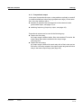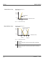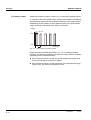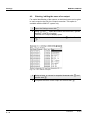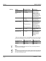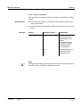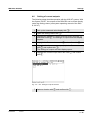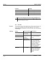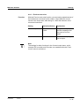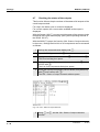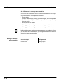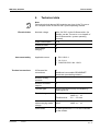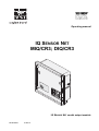
1
Operating manual IQ SENSOR NET MIQ/CR3; DIQ/CR3 OK er Pow ! IQ SENSOR NET combi output module ba76032e01 01/2012 MIQ/CR3; DIQ/CR3 Note For the most recent version of the manual, please visit www.ysi.com. Contact Copyright 2 YSI 1725 Brannum Lane Yellow Springs, OH 45387 USA Tel: +1 937-767-7241 800-765-4974 Email: [email protected] Internet: www.ysi.com © 2012 Xylem Inc. ba76032e01 01/2012 MIQ/CR3; DIQ/CR3 List of contents MIQ/CR3; DIQ/CR3 - List of contents 1 Overview . . . . . . . . . . . . . . . . . . . . . . . . . . . . . . . . . . . . 1-1 1.1 1.2 2 Safety instructions . . . . . . . . . . . . . . . . . . . . . . . . . . . . 2-1 2.1 2.2 3 3.3 3.4 4.2 4.3 4.4 4.5 4.6 01/2012 Scope of delivery . . . . . . . . . . . . . . . . . . . . . . . . . . . . . . 3-1 Installation in the IQ SENSOR NET . . . . . . . . . . . . . . . . . 3-1 3.2.1 Software requirements of the MIQ/CR3 and IQ SENSOR NET . . . . . . . . . . . . . . . . . . . . . . . . . 3-1 Electrical connections: General instructions . . . . . . . . . 3-2 Connections to the relay and current outputs . . . . . . . . 3-4 Settings . . . . . . . . . . . . . . . . . . . . . . . . . . . . . . . . . . . . . 4-1 4.1 ba76032e01 Authorized use . . . . . . . . . . . . . . . . . . . . . . . . . . . . . . . . 2-2 General safety instructions . . . . . . . . . . . . . . . . . . . . . . . 2-2 Installation . . . . . . . . . . . . . . . . . . . . . . . . . . . . . . . . . . 3-1 3.1 3.2 4 How to use this component operating manual . . . . . . . . 1-1 Features of the combi output module . . . . . . . . . . . . . . . 1-2 Basic information on relay functions . . . . . . . . . . . . . . . 4-2 4.1.1 Monitoring . . . . . . . . . . . . . . . . . . . . . . . . . . . . . 4-2 4.1.2 Limit indicator . . . . . . . . . . . . . . . . . . . . . . . . . . 4-3 4.1.3 Proportional output . . . . . . . . . . . . . . . . . . . . . . 4-5 Entering / editing the name of an output . . . . . . . . . . . 4-12 Linking the output with a sensor . . . . . . . . . . . . . . . . . . 4-13 Deleting a link with an output . . . . . . . . . . . . . . . . . . . . 4-14 Setting the relay outputs . . . . . . . . . . . . . . . . . . . . . . . 4-15 4.5.1 Relay action . . . . . . . . . . . . . . . . . . . . . . . . . . 4-16 4.5.2 System monitoring . . . . . . . . . . . . . . . . . . . . . 4-17 4.5.3 Sensor monitoring . . . . . . . . . . . . . . . . . . . . . . 4-18 4.5.4 Limit indicator . . . . . . . . . . . . . . . . . . . . . . . . . 4-19 4.5.5 Frequency controller . . . . . . . . . . . . . . . . . . . . 4-21 4.5.6 Pulse-width contr. . . . . . . . . . . . . . . . . . . . . . . 4-22 4.5.7 Cleaning . . . . . . . . . . . . . . . . . . . . . . . . . . . . . 4-23 4.5.8 Sensor-controlled . . . . . . . . . . . . . . . . . . . . . . 4-27 4.5.9 Manual control . . . . . . . . . . . . . . . . . . . . . . . . . 4-28 4.5.10 Alarm contact . . . . . . . . . . . . . . . . . . . . . . . . . 4-28 Setting of current outputs . . . . . . . . . . . . . . . . . . . . . . . 4-29 4.6.1 Recorder . . . . . . . . . . . . . . . . . . . . . . . . . . . . . 4-30 4.6.2 PID controller . . . . . . . . . . . . . . . . . . . . . . . . . 4-32 4.6.3 Fixed current value . . . . . . . . . . . . . . . . . . . . . 4-37 0-1 List of contents MIQ/CR3; DIQ/CR3 4.7 4.8 4.9 5 Maintenance and cleaning . . . . . . . . . . . . . . . . . . . . . 5-1 5.1 5.2 Maintenance . . . . . . . . . . . . . . . . . . . . . . . . . . . . . . . . . .5-1 Cleaning . . . . . . . . . . . . . . . . . . . . . . . . . . . . . . . . . . . . .5-1 6 Technical data . . . . . . . . . . . . . . . . . . . . . . . . . . . . . . . 6-1 7 Contact Information . . . . . . . . . . . . . . . . . . . . . . . . . . . 7-1 7.1 7.2 8 Ordering & Technical Support . . . . . . . . . . . . . . . . . . . .7-1 Service Information . . . . . . . . . . . . . . . . . . . . . . . . . . . . .7-1 Indexes . . . . . . . . . . . . . . . . . . . . . . . . . . . . . . . . . . . . . 8-1 8.1 0-2 Checking the status of the outputs . . . . . . . . . . . . . . . .4-38 Behavior of linked outputs . . . . . . . . . . . . . . . . . . . . . .4-39 4.8.1 Behavior in case of error . . . . . . . . . . . . . . . . .4-39 4.8.2 Behavior in non-operative condition . . . . . . . .4-40 Maintenance condition of sensors . . . . . . . . . . . . . . . .4-41 4.9.1 Switching on the maintenance condition . . . . .4-42 4.9.2 Switching off the maintenance condition . . . . .4-42 Explanation of the messages . . . . . . . . . . . . . . . . . . . . .8-1 8.1.1 Error messages . . . . . . . . . . . . . . . . . . . . . . . . .8-1 8.1.2 Info messages . . . . . . . . . . . . . . . . . . . . . . . . . .8-1 ba76032e01 01/2012 MIQ/CR3; DIQ/CR3 Overview 1 Overview 1.1 How to use this component operating manual Structure of the IQ SENSOR NET operating manual IQ Sensor Net Operating Manual System Operating Manual (Ring Binder) IQ Sensor Operating Manual MIQ Module Operating Manual MIQ Terminal Operating Manual Component Operating Manuals Fig. 1-1 Structure of the IQ SENSOR NET operating manual The IQ SENSOR NET operating manual has a modular structure like the IQ SENSOR NET itself. It consists of a system operating manual and the operating manuals of all the components used. Please file this component operating manual into the ring binder of the system operating manual. ba76032e01 01/2012 1-1 Overview MIQ/CR3; DIQ/CR3 1.2 General characteristics Features of the combi output module The combi output module has three current outputs and three relay outputs. You can link current outputs and relay outputs to sensors. The linked current outputs and relay outputs can, for example, be used to monitor sensors or to output measurement data. Unlinked relay outputs can be used for general monitoring functions. With the standard MIQ module housing, the combi output module has the same characteristics as all MIQ modules regarding stability, leakproofness and weather resistance. It also provides the same wide variety of installation options (stacked mounting, canopy mounting, tophat rail mounting, etc.). Instrument types Terminal strip The MIQ/CR3 and DIQ/CR3 combi output modules differ in their compatibility with the individual IQ SENSOR NET system families. System Compatible combi output module 2020 XT MIQ/CR3 182 DIQ/CR3 The combi output module has the following electrical connections on the terminal strip inside the housing: 3 x relay contact 3 x current output 2 x SENSORNET connection 1-2 ba76032e01 01/2012 MIQ/CR3; DIQ/CR3 Safety instructions 2 Safety instructions This operating manual contains special instructions that must be followed during the installation of the combi output module. Thus, it is essential for the operator to read this component operating manual before carrying out any work with the system. In addition to this manual, the SAFETY chapter of the IQ SENSOR NET system operating manual must be followed. Always keep this component operating manual together with the system operating manual and all other component operating manuals in the vicinity of the IQ SENSOR NET system. Special user qualifications General safety instructions External circuits carrying mains voltage must only be connected to the relay contacts by a qualified electrician. Safety instructions in this operating manual are indicated by the warning symbol (triangle) in the left column. The signal word (e.g. "Caution") indicates the danger level: Warning indicates instructions that must be followed precisely in order to prevent serious dangers to personnel. Caution indicates instructions that must be followed precisely in order to avoid slight injuries to personnel or damage to the instrument or the environment. Other labels Note This symbol indicates instructions that describe special features. Note indicates cross-references to other documents, e.g. operating manuals. ba76032e01 01/2012 2-1 Safety instructions MIQ/CR3; DIQ/CR3 2.1 Authorized use The authorized use of the combi output module consists of providing relay and current outputs in the IQ SENSOR NET. Please observe the technical specifications according to chapter 6 TECHNICAL DATA. Only operation according to the instructions in this operating manual is authorized. Any other use is considered to be unauthorized. Unauthorized use invalidates any claims with regard to the guarantee. 2.2 General safety instructions The combi output module is constructed and inspected according to the relevant guidelines and norms for electronic instruments (see chapter 6 TECHNICAL DATA). It left the factory in a safe and secure technical condition. Function and operational safety The failure-free function and operational safety of the combi output module is only guaranteed if the generally applicable safety measures and the special safety instructions in this operating manual are followed during its use. The failure-free function and operational safety of the combi output module is only guaranteed under the environmental conditions that are specified in chapter 6 TECHNICAL DATA. Safe operation If safe operation is no longer possible, the combi output module must be taken out of operation and secured against inadvertent operation. Safe operation is no longer possible if the combi output module: has been damaged in transport has been stored under adverse conditions for a lengthy period of time is visibly damaged no longer operates as described in this manual. If you are in any doubt, contact the supplier of your combi output module. 2-2 ba76032e01 01/2012 MIQ/CR3; DIQ/CR3 Installation 3 Installation 3.1 Scope of delivery The scope of delivery of the combi output module is listed in the INSTALLATION chapter of the system operating manual. 3.2 Installation in the IQ SENSOR NET The IQ SENSOR NET provides a number of options for integrating the combi output module mechanically and electrically in the system (stacked mounting, distributed mounting, etc.). The various types of installation are described in detail in the INSTALLATION chapter of the system operating manual. 3.2.1 Software requirements of the MIQ/CR3 and IQ SENSOR NET Software requirements for the use of the Cleaning function: MIQ/CR3: from version 2.20 up Controller: from version 2.20 up If you use a terminal with a software version from 2.20 up, the Clean display flashes. If you use an MIQ/T2020 terminal with a software version lower than 2.20, the Clean display does not appear. The measured value display of the sensor flashes. Software requirements for use of the functions, PID controller, Manual control and Fixed current value: MIQ/CR3: from version 2.30 up Note It is possible to update the software if your components have older software versions. Please contact YSI. ba76032e01 01/2012 3-1 Installation MIQ/CR3; DIQ/CR3 3.3 Cable glands Electrical connections: General instructions All electric cables are fed from below via prepared openings in the enclosure of the module. Cable glands with different clamping ranges are included with the module to provide sealing between the cable and enclosure as well as for strain relief. Select the matching cable gland for the respective cable diameter: Small, clamping range 4.5 to 10 mm. This cable gland is suitable for all IQ SENSOR NET sensor cables. sealing ring 20 x 15 x 1 mm cable gland M16 blind plug Large, clamping range 7 to 13 mm. This cable gland is required for cable sheaths with an outside diameter of more than 10 mm and is screwed into the enclosure via an extension piece. sealing ring 20 x 15 x 1 mm extension piece M16/M20 sealing ring 24 x 19 x 2 mm cable gland M20 Note If necessary, you can order more large cable glands in a set of 4 pieces (Model EW/1, Order No. 480 051). 3-2 ba76032e01 01/2012 MIQ/CR3; DIQ/CR3 General installation instructions Installation Observe the following points when attaching connecting wires to the terminal strip Shorten all wires to be used to the length required for the installation Always fit all the ends of the wires with wire end sleeves before connecting them to the terminal strip Any wires that are not used and project into the enclosure must be cut off as closely as possible to the cable gland. Screw a small cable gland with sealing ring into each remaining free opening and close it with a blind plug. Warning No free wires must be allowed to project into the enclosure. Otherwise, there is a danger that areas safe to contact could come into contact with dangerous voltages which could result in life threatening electric shock when working with the IQ SENSOR NET. Always cut off any wires that are not in use as closely as possible to the cable gland. ba76032e01 01/2012 3-3 Installation MIQ/CR3; DIQ/CR3 3.4 Connections to the relay and current outputs Warning If external electrical circuits that are subject to the danger of physical contact are incorrectly connected to the relay contacts, there may be a danger of life threatening electric shock. Electrical circuits are regarded to be subject to the danger of physical contact when there are voltages higher than the Safety Extra Low Voltage (SELV). Pay attention to the following points during installation: Electrical circuits subject to the danger of physical contact must only be connected by a qualified electrician. Electrical circuits subject to the danger of physical contact must only be connected when they are voltage-free. If electrical circuits subject to the danger of physical contact are switched with a relay, no circuit that is not subject to this danger (e. g. the MIQ/CHV module) may be operated in the same output module. Use an additional output module for such applications. Switching voltages and switching currents on the relay contacts must not exceed the values specified in chapter 6 TECHNICAL DATA. Protect electrical circuits against currents that are too high with an electrical fuse. Only single-phase consumers can be switched with the relays. Under no circumstances must multiphase consumers be switched with the aid of several relays (example three-phase current driven pumps). Always switch multiphase consumers via a protective relay. After the output module has been installed, it may only be opened if all external voltages have been switched off beforehand. Materials required Wire end sleeves, suitable for the connecting wires, with suitable crimping tool 4 x screwed cable gland with sealing ring (scope of delivery of the combi output module). Tools Cable stripping knife Wire stripper Phillips screw driver Small screw driver 3-4 ba76032e01 01/2012 MIQ/CR3; DIQ/CR3 Connecting lines to the terminal strip Installation 1 Open the module. 2 X15 X13 R3 X10 X9 X8 X7 + REC C1 + REC C2 + REC C3 X6 X5 X4 ON OFF SENSORNET 2 X3 X2 X1 GREEN R2 X11 GREEN R1 X12 0/4...20mA 0/4...20mA 0/4...20mA RED 250 VAC 5 A AC Relay Fig. 3-1 X14 250 VAC 5 A AC RED X16 SHIELD X17 250 VAC 5 A AC SN TERMINATOR X18 SHIELD 1 3 SENSORNET 1 Current output Terminal strip with the relay and current connections 2 Screw the cable gland (pos. 1 in Fig. 3-1) with the sealing ring (pos. 2) into the module housing. 3 Loosen the coupling ring (pos. 3 in Fig. 3-1). 4 Feed the line through the cable gland in the module housing. 5 Connect the wires to the terminal strip. While doing so, pay attention to the specifications on the label located under the terminal strip. 6 Tighten the coupling ring (pos. 3 in Fig. 3-1). Warning No free wires must be allowed to project into the enclosure. Otherwise, there is a danger that safe areas could come into contact with dangerous voltages. This could result in life threatening electric shock when working with the IQ SENSOR NET. Always cut off any wires that are not in use as closely as possible to the cable gland. ba76032e01 01/2012 3-5 Installation MIQ/CR3; DIQ/CR3 7 3-6 Close the module. ba76032e01 01/2012 MIQ/CR3; DIQ/CR3 Settings 4 Settings The combi output module has three relays outputs and three current outputs. Relay outputs operate as openers or closers. Current outputs provide a current that depends on the measured value. On the terminal or Universal Transmitter, you can assign names to the outputs (with the 2020 XT system only, see section 4.2). link outputs with sensors (see section 4.3) delete links of outputs with sensors (see section 4.4) adjust outputs (see section 4.5 and section 4.6) check the condition of the outputs (see section 4.7) Basic information on how to use relay outputs is given in section 4.1. Note The general operating principles are given in the relevant system operating manual or in the component operating manual of the terminal components. Functions of current and relay outputs Relay output (see section 4.5) System monitoring Sensor monitoring Limit indicator Frequency controller Pulse-width contr. Cleaning Sensor-controlled Manual control Alarm contact (with the 2020 XT system only) Current output (see section 4.6) Recorder PID controller Fixed current value ba76032e01 01/2012 4-1 Settings MIQ/CR3; DIQ/CR3 4.1 Basic information on relay functions In this chapter, you will find general basic information concerning the following relay functions: Monitoring (see section 4.1.1) Limit indicator (see section 4.1.2) Proportional output (see section 4.1.3) 4.1.1 Monitoring When using a relay for monitoring, a relay action (Open, Close) occurs when certain states occur. This function is suitable, e.g. for the monitoring of errors in the system. Note For monitoring functions, use the relay preferably as an opener (see section 4.5.1). In the case of an error, the relay opens. As a result, the monitoring function operates even if, e.g. the supply voltage fails. 4-2 ba76032e01 01/2012 MIQ/CR3; DIQ/CR3 Settings 4.1.2 Limit indicator With a limit indicator, a relay switches when a specified limiting value is exceeded or undercut. Limit indicators can be used in the following way: Monitoring a limiting value using a relay: when a limiting value (upper or lower limiting value) is exceeded or undercut, a relay switches. The Open or Close relay actions are possible in each case (see page 4-4). Monitoring two limiting values using two relays: If the upper limiting value is exceeded or undercut, a relay switches, and if the lower limiting value is exceeded or undercut, another relay switches. The Open or Close relay actions are possible in each case (see page 4-4). Note If the simple monitoring function (Open, Close) with one or two relays is not sufficient, use proportional output (see section 4.1.3). ba76032e01 01/2012 4-3 Settings Monitoring limiting values using one or two relays MIQ/CR3; DIQ/CR3 Measured value t1 t1 Relay 1 UL Hysteresis UL 2 1 6 4 3 5 LL Hysteresis LL Relay 2 t2 t2 Time Fig. 4-1 Switching points for relays with the function of a limit indicator 1 Upper limit value (relay 1) exceeded 2 Selected switching delay t1 for relay 1 expired Relay 1 switches 3 Hysteresis for upper limiting value (relay 1) undercut 4 Selected switching delay t1 for relay 1 expired Relay 1 switches back 5 Lower limit value (relay 2) undercut Selected switching delay t2 for relay 2 expired Relay 2 switches 6 Hysteresis for lower limiting value (relay 2) exceeded Selected switching delay t2 for relay 2 expired Relay 2 switches back A switching delay (t) can be set up for each relay for switching processes. This is the time period for which a limiting value must be exceeded before the relay switches. This prevents frequent switching if the measured values are close to the limiting value. 4-4 ba76032e01 01/2012 MIQ/CR3; DIQ/CR3 Settings 4.1.3 Proportional output In the case of proportional output, a relay switches cyclically on and off in a defined measured value range (proportional range). At the same time, the relay switches with a: duration of operation that corresponds to the measured value (pulse-width output, see page 4-7) or switching frequency (frequency output, see page 4-8). Proportional outputs can be used in the following way: Output with one relay: An output range is defined with a Start value and an End value. No output takes place above and below the output range (see page 4-6). Output with two relays: An output range is defined for each relay with a Start value and an End value. One relay outputs in the upper output range and a further relay in the lower output range (see page 4-6). ba76032e01 01/2012 4-5 Settings Output with one relay MIQ/CR3; DIQ/CR3 Switching frequency f or Pulse width v 100 90 Proportional band 10 0 Measured value 1 Fig. 4-2 Output with two relays 2 Output with one relay Switching frequency f or Pulse width v Proportional bands Relay 1 and 2 100 90 10 Measured value 0 1 2 Relay 1 Fig. 4-3 4-6 1 2 Relay 2 Output with two relays 1 Start value Measured value with a minimum pulse width or switching frequency 2 End value Measured value with a maximum pulse width or switching frequency ba76032e01 01/2012 MIQ/CR3; DIQ/CR3 Pulse width output Settings The output of the pulse width is used, e.g. for controlling valves. Pulse-width regulation changes the duration of operation (ton) of the output signal. Depending on the position of the measured value in the proportional range, the relay is operated for a longer or shorter time period. Relay tOn t Off On Off T Fig. 4-4 Time [s] Relay output of the pulse-width output The cycle duration (T) is made up of the turn-on and turn-off switching duration (ton, toff) of the relay together. While the selected cycle duration (T) remains constant, the turn-on duration (ton) changes depending on the measured value and, with it, the pulse width (v). The pulse width can be set from 0 % to 100 %. v = (ton / T) * 100 % v = pulse width, T = cycle duration, ton = turn-on duration If the measured value is at the end of the proportional range (End value), the turn-on duration (ton) is long, the turn-off duration is short. This means the relay operates for a longer period. If the measured value is at the beginning of the proportional range (Start value), the turn-on duration (ton) is short, and the relay operates for a correspondingly shorter period. Note If the duration of the closing or opening pulse is shorter than 0.1 s, the relay remains open or closed for the complete cycle duration. ba76032e01 01/2012 4-7 Settings Frequency output MIQ/CR3; DIQ/CR3 Switching frequency output is used, e.g. for controlling dosing pumps. In contrast to the pulse-width output, not the pulse width is modulated with frequency output but the switching frequency of the output signal. Depending on the position of the measured value in the proportional range, the relay is switched more often or less often. Relay tOn = 0.3 s On Off T Fig. 4-5 Time [s] Relay output of frequency output While the selected switching duration (ton = 0.3 s) always remains constant, the switching frequency at which the relay switches changes depending on the measured value. If the measured value is at the end of the proportional range (End value), the switching frequency is higher. If the measured value is at the beginning of the proportional range (Start value), the switching frequency is low. 4-8 ba76032e01 01/2012 MIQ/CR3; DIQ/CR3 Characteristic curves Settings Through the selection of the Start value and End value, the proportional output can be operated with a positive or negative characteristic curve. Positive characteristic curve: Select the End value to be greater than the Start value. The turn-on duration or frequency increases with an increasing measured value (see page 4-10). Negative characteristic curve: Select the End value to be smaller than the Start value. The turn-on duration or frequency decreases with an increasing measured value (see page 4-11). The maximum values for the pulse width or switching frequency are assigned to the End value and the minimum values for turn-on duration or frequency are assigned to the Start value. Switching frequency f or Pulse width v Max. Min. Start value Fig. 4-6 End value Measured value Positive characteristic curve Switching frequency f or Pulse width v Max. Min. End value Fig. 4-7 ba76032e01 01/2012 Start value Measured value Negative characteristic curve 4-9 Settings Positive characteristic curve MIQ/CR3; DIQ/CR3 The proportional output range begins above the initial value. If the proportional range is undercut or exceeded, the selected behavior comes into force. Pulse width v [%] 90% 100 90 Cycle duration T 50 Proportional band 10 0 50% 50% tOn tOf f 10% 90% Time 1 Fig. 4-8 10% Measured value 2 Pulse width output Switching frequency f [1/min] 120 Maximum switching frequency 60 Proportional band 50 % of maximum switching frequency Time 0 1 Fig. 4-9 4 - 10 Measured value 2 Minimum switching frequency Frequency output 1 Start value Measured value with a minimum pulse width or switching frequency 2 End value Measured value with a maximum pulse width or switching frequency ba76032e01 01/2012 MIQ/CR3; DIQ/CR3 Negative characteristic curve Settings The proportional output range begins below the initial value. If the proportional range is undercut or exceeded, the selected behavior comes into force. Pulse width v [%] 90% 100 90 10% Cycle duration T 50 Proportional band 10 0 50% 50% tOn tOf f 10% 90% Time 2 Measured value 1 Fig. 4-10 Pulse width output Switching frequency f [1/min] 100 Maximum switching frequency 50 Proportional band 50 % of maximum switching frequency Time 0 2 Measured value 1 Minimum switching frequency Fig. 4-11 Frequency output ba76032e01 01/2012 1 Start value Measured value with a minimum pulse width or switching frequency 2 End value Measured value with a maximum pulse width or switching frequency 4 - 11 Settings MIQ/CR3; DIQ/CR3 4.2 Entering / editing the name of an output For easier identification of the outputs, an individual name can be given to each output in the Edit list of outputs overview. This option is available with the 2020 XT system only. 1 Open the Settings menu with s. 2 Using d and g, select and confirm the menu item, System settings -> Edit list of outputs. The Edit list of outputs display opens. 3 Highlight a name in the Name column with d and confirm with g. Fig. 4-12 130 - Edit list of outputs 4 - 12 4 Select a letter, a numeral or a special character with d and confirm with g. 5 Complete the name of the output and confirm with g. ba76032e01 01/2012 MIQ/CR3; DIQ/CR3 Settings 4.3 Linking the output with a sensor The following steps describe operation with the 2020 XT system. With the System 182 XT, the outputs of the DIQ/CR3 can be found directly under the Settings menu (see system operating manual of the DIQ/ S 182 XT). 1 Open the Settings menu with s. 2 Using d and g, select and confirm the menu item, System settings -> Settings of outputs and links. The Settings of outputs and links display opens. 3 Highlight the column with d and confirm with g. 4 Highlight an output with d and confirm with g. The Link with... display opens. The display shows a list of the sensors to which a link is possible. Fig. 4-13 150 - Settings of outputs and links:Link with... 5 Select a sensor with d and confirm with g. The output is linked with the selected sensor. Note Outputs that are linked with sensors can be identified in the Ser. no. field of the Settings of outputs and links overview by the specification of the linked sensor. ba76032e01 01/2012 4 - 13 Settings MIQ/CR3; DIQ/CR3 4.4 Deleting a link with an output If a link from a current or relay output with a sensor is no longer required, the link can be deleted. The following steps describe operation with the 2020 XT system. With the System 182 XT, the outputs of the DIQ/CR3 can be found directly under the Settings menu (see system operating manual of the DIQ/ S 182 XT). 1 Open the Settings menu with s. 2 Using d and g, select and confirm the menu item, System settings -> Settings of outputs and links. The Settings of outputs and links display opens. 3 Highlight the column & with d and confirm with g. 4 Highlight a linked output with d and confirm with g. Fig. 4-14 150 - Settings of outputs and links:Erase link 4 - 14 5 Select Erase link with d and confirm with g. A security prompt appears. 6 Select Erase link with d and confirm with g. The link is deleted. ba76032e01 01/2012 MIQ/CR3; DIQ/CR3 Settings 4.5 Setting the relay outputs The following steps describe operation with the 2020 XT system. With the System 182 XT, the outputs of the DIQ/CR3 can be found directly under the Settings menu (see system operating manual of the DIQ/ S 182 XT). 1 Call up the measured value display with m. 2 Open the Settings menu with s. 3 Highlight the Settings of outputs and links menu item with d and confirm with g. The Settings of outputs and links display appears. 4 Highlight the Feature column with d and confirm with g. 5 Highlight a line for a relay output (Rx) in the Feature column with d and confirm with g. The Settings of outputs and links display opens. 6 Highlight the Relay function menu item with d and confirm with g. Fig. 4-15 150 - Settings of outputs and links 7 ba76032e01 01/2012 Select one of the functions in the following list with d and confirm with g. 4 - 15 Settings MIQ/CR3; DIQ/CR3 Function Description No function The relay output is not used. System monitoring see section 4.5.2 Sensor monitoring see section 4.5.3 Limit indicator see section 4.5.4 Frequency controller see section 4.5.5 Pulse-width contr. see section 4.5.6 Cleaning see section 4.5.7 Sensor-controlled see section 4.5.8 Manual control see section 4.5.9 Alarm contact see section 4.5.10 8 Carry out the settings for the relay outputs with d and g. The settings include the relay action (see section 4.5.1) and sensor-dependent settings. 9 Highlight and confirm Save and quit with d and g. The new settings are stored. As soon as a function is selected for a relay output, a relay action can be selected (see section 4.5.1). 4.5.1 Relay action The following actions of the relay can be laid down in the Action setting: Settings Explanations Open The relay should open if any event occurs. Close The relay should close if any event occurs. Note Preferably set up the relay output as normally closed for monitoring functions (Action Open). 4 - 16 ba76032e01 01/2012 MIQ/CR3; DIQ/CR3 Settings 4.5.2 Function System monitoring The System monitoring enables to monitor system errors. In order to set up the System monitoring function for a relay output, the relay output must not be linked with a sensor (see section 4.3). It can be used to monitor the following system errors. Settings Collective error message Settings Selection Explanations Power failure On Off The Power failure On function monitors the supply voltage in the IQ SENSOR NET on the combi output module. If the voltage falls below the critical value, the relay switches. Communication On Off The Communication On function monitors the functioning of the controller and the communication to the combi output module. Collective error message On Off The Collective error message On function simultaneously monitors the proper functioning of all sensors and the functioning of the monitoring combi output module. (for details see below this table) Action Open For all functions of the System monitoring, the relay action is set to Open. In the case of a Collective error message, the relay opens if one of the following malfunctions occurs: One of the sensors properly registered at the controller does not supply a valid main measured value One of the sensors properly registered at the controller does not supply a valid secondary measured value The monitoring combi output module has not received any new data from the controller for two minutes. In any case, the relay remains open for 10 seconds and only closes when the malfunction is no longer present. In the following cases, the relay does not open despite an invalid measured value: ba76032e01 01/2012 4 - 17 Settings MIQ/CR3; DIQ/CR3 The sensor is being calibrated The sensor is in the maintenance condition The sensor is being cleaned with the aid of a valve module in the system (compressed air operated cleaning system). 4.5.3 Function Sensor monitoring The Sensor monitoring function enables to monitor sensor errors and the maintenance condition. In order to set up the Sensor monitoring function for a relay output, the relay output must be linked with a sensor (see section 4.3). Settings Setting Selection Explanation Errors Special Special sensor errors are monitored and can prompt a relay action. All All sensor errors (special ones and general ones) are monitored and can prompt a relay action. Off Sensor errors are not monitored. Mainten. Condition On Off Switching on and off the maintenance condition (see section 4.9) is monitored and can prompt a relay action. Action Open Close Relay action (see section 4.5.1) Note Preferably set up the relay output as opener for monitoring functions (Action Open, see section 4.5.1). Sensor messages include errors and information that are registered by the sensor. Special sensor errors 4 - 18 The special sensor errors are sensor-dependent. Details of this are given in the component operating manual of the respective sensor. ba76032e01 01/2012 MIQ/CR3; DIQ/CR3 General sensor errors Settings Init can prompt a relay action for a short time, depending on the starting behavior of the system ---- Invalid measured value, or defective sensor Error Communication with sensor interrupted OFL Measuring range undercut or exceeded (overflow) 4.5.4 Function Limit indicator The characteristic of the limit indicator is laid down in the Limit value UL, Limit value LL, Hysteresis UL and Hysteresis LL settings. The fundamentals of the function are described in the introductory chapter (see section 4.1.2). In order to set up the Limit indicator function for a relay output, the relay output must be linked with a sensor (see section 4.3). Settings Setting Selection/Values Explanation Limit values UL main variable LL main variable Main variable designates the actual measured parameter of the sensor (e.g. pH, oxygen, etc.). Adjoining variable designates an additional measured parameter (e.g. temperature). UL adjoining var. LL adjoining var. Limit value UL Limit value LL Hysteresis UL Hysteresis LL ba76032e01 01/2012 Any upper and lower limiting value within the measuring range (sensordependent) Minimum spacing between the upper and lower limiting value: 5 % of the measuring range 0 - 5% of the measuring range Hysteresis for Limit value UL and Limit value LL. 4 - 19 Settings 4 - 20 MIQ/CR3; DIQ/CR3 Setting Selection/Values Explanation Behavior at error Open Close Unchanged The relay opens, closes, or remains unchanged in case of system errors or sensor errors (see page 4-39). Action Open Close Relay action (see section 4.5.1) Switching delay 0 ... 3600 s The time period for which a limiting value must be exceeded before the relay operates. Prevents frequent switching for measured values that are close to the limiting value. ba76032e01 01/2012 MIQ/CR3; DIQ/CR3 Settings 4.5.5 Function Frequency controller The characteristic of the frequency output is laid down in the Start value, End value, Frequency (f) min. and Frequency (f) max. settings. The fundamentals of the function are described in the introductory chapter (see section 4.1.3). In order to set up the Frequency controller function for a relay output, the relay output must be linked with a sensor (see section 4.3). Settings Setting Selection/Values Explanation Measured variable Main variable Adjoining variable Main variable designates the actual measured parameter of the sensor (e.g. pH, oxygen, etc.). Adjoining variable designates an additional measured parameter (e.g. temperature). Start value End value within the measuring range (sensordependent) Minimum spacing: 5 % of the measuring range Frequency (f) min. 0 to 120 1/min Minimum spacing: 10 1/min Frequency with error 0 to 120 1/min In case of system errors or sensor errors (see page 439), the relay switches with the frequency specified. Action Open Close Relay action (see section 4.5.1) Frequency (f) max. Characteristic curve If a value is entered for End value that is greater than the Start value, the output has a positive characteristic curve. In order to obtain a negative characteristic curve, a value must be entered for End value that is smaller than the value for Start value. ba76032e01 01/2012 4 - 21 Settings MIQ/CR3; DIQ/CR3 4.5.6 Function Pulse-width contr. The characteristic of the pulse width output is laid down in the Start value, End value, Pulse width (v) min. and Pulse width (v) max. settings. The fundamentals of the function are described in the introductory chapter (see section 4.1.3). In order to set up the Pulse-width contr. function for a relay output, the relay output must be linked with a sensor (see section 4.3). Settings Setting Selection/Values Explanation Measured variable Main variable Adjoining variable Main variable designates the actual measured parameter of the sensor (e.g. pH, oxygen, etc.). Adjoining variable designates an additional measured parameter (e.g. temperature). Start value End value within the measuring range (sensordependent) Minimum spacing: 5 % of the measuring range Pulse width (v) min. 0 ... 100 % Minimum spacing: 10 % of the Cycle duration (T) Cycle duration (T) 5 ... 100 s Length of the switching period T T = (ton + toff) Error pulse width 0 ... 100 % In case of system errors or sensor errors (see page 439), the relay switches with the pulse-width specified. Action Open Close Relay action (see section 4.5.1) Pulse width (v) max. Characteristic curve 4 - 22 You can specify the minimum and maximum pulse width (v). This determines the steepness of the characteristic curve of the output. ba76032e01 01/2012 MIQ/CR3; DIQ/CR3 Settings 4.5.7 Cleaning Note When using the MIQ/CHV PLUS valve module, it is best to set the Cleaning function directly at the valve output (V) of the MIQ/CHV PLUS (see operating manual of the MIQ/CHV PLUS). The relay can then be used for other purposes. Function The Cleaning function enables the time controlled automatic start of the sensor cleaning function with the aid of a relay of the combi output module. The relay controls the MIQ/CHV valve module and switches on or off the compressed air for the CH sensor cleaning head. In order to set up the Cleaning function for a relay output, the relay output must be linked with a sensor (see section 4.3). The relay assigned to the combi output module always works as a closer. The cleaning cycle consists of Cleaning duration and Adjustment time. During the cleaning cycle the Clean display flashes. The outputs linked with this sensor are frozen. The maintenance condition (see section 4.9) is active. After the Cleaning duration, the relay is opened. During the following Adjustment time the outputs remain blocked. The outputs linked with this sensor are only released when the cleaning cycle is completed. The Clean display disappears. The maintenance condition is finished. Testing the operativeness You can test the operativeness of the cleaning system as follows: manually open or close the relay with the Manual control function (see section 4.5.9) and, while doing so, check the behavior of the cleaning system. Alternatively, you can test the operativeness of the cleaning system by checking the performance of the function at the start time set up (reference time ± interval). To perform a test immediately, you can set the reference time so that the next cleaning will start in a few minutes (settings: see following table). ba76032e01 01/2012 4 - 23 Settings MIQ/CR3; DIQ/CR3 Settings Setting Selection/Values Explanation Reference time (h) 0 ... 23 h Reference time (min) 0 ... 60 min Time at which a cleaning cycle is started. Further cleaning cycles will be performed at the times specified by the cleaning interval. Interval unit 1 .. 7 d 1 .. 24 h 5 .. 60 min Selection of range and unit for the Cleaning interval. Cleaning interval 1/2/3/4/5/6/7 d Repeat interval for the cleaning function: Time between the start time of a cleaning cycle and the start time of the next cleaning cycle*. or: 1/2/3/4/6/8/12/24 h or: 5/10/15/20/30/60 min Cleaning duration 0 ... 300 s Duration of the cleaning Adjustment time 0 ... 900 s Time extension to allow the sensor to adjust to the test sample after the cleaning. * With short cleaning intervals, the adjustable values for the Cleaning duration and Adjustment time are limited. The following values apply: Cleaning interval Cleaning duration Adjustment time ≤ 10 min max. 60 s max. 120 s ≤ 20 min max. 180 s max. 300 s Note With this, the cleaning times are fixed. They only change when the reference time is changed. Note The reference time and all further cleaning times relate to the date and time of the system clock. How to set the system clock is described in the system operating manual. 4 - 24 ba76032e01 01/2012 MIQ/CR3; DIQ/CR3 Example Settings Setting Result Reference time (h): Reference time (min): Interval unit: Cleaning interval: 12 0 Hours (h) 8h Reference time: 12:00 hours This specifies the following start times: 04:00, 12:00 and 20:00 hours 2 1 3 t1a t1b relay condition 4 t1 1 4 t1 t1 closed open t2 t2 00:00 04:00 t2 12:00 t2 20:00 24:00 Time Fig. 4-16 Cleaning cycle ba76032e01 01/2012 1 Reference time Start of a cleaning cycle (t1) Start of the specified Cleaning duration (t1a) 2 End of the specified Cleaning duration (t1a) Start of the specified Adjustment time (t1b) 3 End of the specified Adjustment time (t1b) End of the cleaning cycle (t1) 4 Reference time ± Cleaning interval (t2) Start of a cleaning cycle t1 Cleaning cycle = Cleaning duration (t1a) Adjustment time (t1b) Linked outputs are frozen. t2 Cleaning interval 4 - 25 Settings Canceling the cleaning MIQ/CR3; DIQ/CR3 A running cleaning cycle is canceled: Automatically – If the sensor switches to the inactive condition during the cleaning cycle Manually – By pressing c – By switching on the maintenance condition Each time the cleaning cycle is canceled, the relay opens immediately. If the cleaning cycle is canceled automatically, the outputs linked to the sensor are released immediately. If the cleaning cycle is canceled manually, the sensor is in the maintenance condition. The linked outputs are only released after the maintenance condition was terminated manually. The next cleaning cycle will be performed at the time set up. Note In case of a power failure, all relays open. The cleaning cycle is canceled. The outputs linked with the sensor change to the non-active condition (see section 4.8.2). As soon as the power is available, the outputs are released again. The next cleaning cycle will be performed at the time set up. 4 - 26 ba76032e01 01/2012 MIQ/CR3; DIQ/CR3 Settings 4.5.8 Sensor-controlled With the Sensor-controlled function, the relay is controlled by a linked sensor. Requirements For the 2020 XT system, a controller with a software version from 2.80 up is required Sensor that transmits signals to trigger a cleaning cycle, e.g. UV/VIS sensor Settings Setting Selection/Values Explanation Pulse length Automatic The duration of the air cleaning process is programmed in the sensor. The relay automatically takes over the cleaning duration from the sensor. 0,5 s 1s 2s 3s The relay finishes the cleaning after the selected interval. Note Settings of the cleaning process can be done in the Settings of sensors and diff. sensors menu of the respective sensor. ba76032e01 01/2012 4 - 27 Settings MIQ/CR3; DIQ/CR3 4.5.9 Function Manual control With the Manual control function, you can test the operativeness of an instrument that is connected to the relay. To do so, close or open the relay manually and, while doing so, check the behavior of the connected instrument. Setting Selection/Values Explanation Relay function Manual control The selected relay action is carried out with Save and quit. Action Open Close Relay action (see section 4.5.1) Note The settings for other functions in the Relay function menu, as for example Frequency controller and Pulse-width contr., are retained while the Manual control is carried out. 4.5.10 Alarm contact Note The Alarm contact function is only effective with systems with alarm function (System 2020 XT). Function The Alarm contact function triggers a relay action (close or open) if a specified alarm event occurs. The Alarm contact function is only available for relays that are not linked with a sensor. If necessary, an existing link has to be deleted. Setting Selection/Values Explanation Relay function Alarm contact The selected relay action is carried out with Save and quit. Action Open Close Relay action (see section 4.5.1) Note The setting up of alarms is described in the IQ SENSOR NET system operating manual. Other possibilities of how to use the alarm function are described there as well. 4 - 28 ba76032e01 01/2012 MIQ/CR3; DIQ/CR3 Settings 4.6 Setting of current outputs The following steps describe operation with the 2020 XT system. With the System 182 XT, the outputs of the DIQ/CR3 can be found directly under the Settings menu (see system operating manual of the DIQ/ S 182 XT). 1 Call up the measured value display with m. 2 Open the Settings menu with s. 3 Highlight the Settings of outputs and links menu item with d and confirm with g. The Settings of outputs and links display appears. 4 Highlight the Feature column with d and confirm with g. 5 Highlight a line for a current output (Cx) in the Feature column with d and confirm with g. The Settings of outputs and links display opens. 6 Highlight the Current output menu item with d and confirm with g. Fig. 4-17 150 - Settings of outputs and links 7 ba76032e01 01/2012 Select a function with d and confirm with g. 4 - 29 Settings MIQ/CR3; DIQ/CR3 Function Settings No function The current output is not used. Recorder see section 4.6.1 PID controller see section 4.6.2 Fixed current value see section 4.6.3 8 Carry out the settings for the current output with d and g. 9 Highlight and confirm Save and quit with d and g. The new settings are stored. 4.6.1 Recorder Function The measured values of the linked sensor at the current output are set up as current intensity in the Recorder application. The output of measured values is laid down in the Recorder type, Start value and End value settings. Settings Setting Selection/Values Recorder type 0 to 20 mA or 4 to 20 mA Start value within the measuring range (sensordependent) Minimum spacing: 5 % of the measuring range Measured variable Main variable Adjoining variable Main variable designates the actual measured parameter of the sensor (e.g. pH, oxygen, etc.). Adjoining variable designates an additional measured parameter (e.g. temperature). Attenuation 0 ... 40 mA/s Speed of change of the output current (mA/s) in the case of an erratic change of the input signal. End value 4 - 30 Explanation ba76032e01 01/2012 MIQ/CR3; DIQ/CR3 Settings I -> OFL/UFL Behavior at error ba76032e01 01/2012 Error Current values outside the range between Start value and End value are considerd as errors. The current output reacts as specified under Behavior at error (see below). Limitation The current at the output is limited to the Start value or End value. Fixed current value In case of system errors and sensor errors, and in case of measured values outside the range between Start value and End value, the current output supplies the specified fixed current value. Possible values: 0 ... 21 mA. Unchanged The current at the output remains unchanged. 4 - 31 Settings MIQ/CR3; DIQ/CR3 4.6.2 Function PID controller With the PID controller function, you can use an output as a controller output. The controller can be configured as a Proportional controller with a switchable Integral and Derivative controller part (PID controller). The control mode of the PID controller is described by the following equation: 1 dx I Controller = I 0 + K xe + xe dt + Td e Ti dt with: K= I max − I min Xp xe = xnom − xactual I min ≤ I Controller ≤ I max IController Current at the controller output at time t I0 Current at output if xactual = xnominal K Gain Xp Proportional band xe Error signal xactual Actual value (current measured value) xnom Nominal value ti Integral control part td Derivative control part t Time Imin Lower current limitation Imax Upper current limitation The adjustable control parameters are xnominal , I0 , Xp , Imin , Imax , ti and Td (see setting table on page 4-35). 4 - 32 ba76032e01 01/2012 MIQ/CR3; DIQ/CR3 Settings By activating or deactivating the Integral (ti) and Derivative (td) controller part, the following controller types can be configured: Characteristic curve of the proportional controller Controller type td [s] ti [s] P controller 0 0 PI controller 0 1 to 9999 PD controller 1 to 9999 0 PID controller 1 to 9999 1 to 9999 For a P controller, the interrelationship between the measured value and current I at the controller output forms the following characteristic curve: Current I [mA] Imax Xp Io Imin 0 Nominal value Measured value Fig. 4-18 Proportional controller (negative characteristic curve) The proportional band Xp is limited by the measuring range of the linked sensor. If a value is entered for the parameter Xp that is greater than zero, the controller has a negative characteristic curve (example Fig. 4-18). To obtain a positive characteristic curve, a negative value must be entered for Xp . ba76032e01 01/2012 4 - 33 Settings Application example MIQ/CR3; DIQ/CR3 Feedback control of the D. O. concentration Sensor: TriOxmatic 700 IQ (measuring range: 0 ... 60 mg/l) Control parameters Value Nominal value 4 mg/l Xp 10 % of the measuring range or 6 mg/l Imin 8 mA Imax 14 mA Io 12 mA ti 0 s (no I controller part) td 0 s (no D controller part) The control parameters form the following (negative) characteristic curve: Current I [mA] Xp Imax 14 Io 12 Imin 8 0 2 4 8 Measured value [mg/l] Nominal value Fig. 4-19 Characteristic curve for application example The controller works with the following gain: K = 4 - 34 6 mA mA =1 6 mg/l mg/l ba76032e01 01/2012 MIQ/CR3; DIQ/CR3 Settings Within the proportional band, a concentration increase by 1 mg/l causes a decrease of the current output by 1 mA. If, for example, the measured concentration is 5 mg/l, 11 mA are output: I Controller = 12 mA + 1 I Controller = 12 mA + 1 mA ⋅ (4 mg/l − 5 mg/l ) mg/l mA ⋅ (− 1 mg/l) = 11 mA mg/l The highest concentration with which the controller works within the proportional band is 8 mg/l (corresponding to Imin = 8 mA), the lowest one is 2 mg/l (corresponding to Imax = 14 mA). Settings Setting Selection/Values Explanation Measured variable Main variable Adjoining variable Main variable designates the actual measured parameter of the sensor (e.g. pH, oxygen, etc.). Adjoining variable designates an additional measured parameter (e.g. temperature). Nominal value within the measuring range (sensordependent) Nominal value the measured value is regulated to Xp 5 ... 100 % -5 ... -100 % of the measuring range Proportional band of the controller. Negative values result in a positive characteristic curve. Imin 0 ... 20 mA Lower current limitation * Imax 0 ... 20 mA Upper current limitation * * Note: Spacing between Imin and Imax: at least 5 mA ba76032e01 01/2012 4 - 35 Settings 4 - 36 MIQ/CR3; DIQ/CR3 Setting Selection/Values Explanation Io 0 ... 20 mA Current value on the output if the measured value equals the Nominal value ti 0 ... 9999 s Hold-back time: Integral part of the controller (0 = not effective) td 0 ... 9999 s Reset time: Derivative part of the controller (0 = not effective) Behavior at error Fixed current value In the case of an error, the current output supplies the current value defined in the Current with error field (any in the range 0 ... 21 mA). Unchanged In the case of an error, the current on the output remains unchanged. ba76032e01 01/2012 MIQ/CR3; DIQ/CR3 Settings 4.6.3 Function Fixed current value With the Fixed current value function, you can test the operativeness of the instruments connected to the outputs: output different current values to the output and, while doing so, check the behavior of the connected instrument. Setting Selection/Values Explanation Current output Fixed current value Using Save and quit, the nominal amperage that was input as Inom is output. Inom 0 ... 20 mA The nominal amperage that is output. Note The settings for other functions in the Current output menu, as for example PID controller and Recorder, are retained while the Fixed current value is carried out. ba76032e01 01/2012 4 - 37 Settings MIQ/CR3; DIQ/CR3 4.7 Checking the status of the outputs This function offers a simple overview of the states of all outputs of the combi output module. For relays, the status open or closed is displayed. For current outputs, the current value available at the output is displayed. With the System 182 XT, you can recall the states of the outputs via the measured value and status display (see system operating manual of the DIQ/S 182 XT). With the 2020 XT system, the function, 394 - Status of output channels, in the menu, Settings/Service/List of all components can be accessed as follows: 1 Call up the measured value display with m. 2 Open the Settings menu with s. 3 Highlight the Service menu item with d and confirm with g. The Service dialog box opens. 4 Highlight the List of all components menu item with d and confirm with g. The List of all components dialog box opens. 5 Select the required component (column Model, entry MIQCR3) with d and confirm with g. The 394 - Status of output channels window opens. Fig. 4-20 394 - Status of output channels 6 4 - 38 Using m or e, exit the 394 - Status of output channels window. ba76032e01 01/2012 MIQ/CR3; DIQ/CR3 Settings 4.8 Behavior of linked outputs 4.8.1 Behavior in case of error For linked relay outputs or current outputs, you can determine the behavior of the outputs in case of errors. Depending on the use of the output, the behavior in case of errors is set in the following menus: Error events Output menu Frequency controller Frequency with error (see section 4.5.5) Pulse-width contr. Error pulse width (see section 4.5.6) Recorder Current with error (see section 4.6.1) The defined behavior occurs in the case of the following events or conditions: The linked sensor does not supply a valid measured value (display of Init, Error, "-----", or OFL) Communication of the MIQ/CR3; DIQ/CR3 with the IQ SENSOR NET controller is disturbed for longer than 2 minutes. The supply voltage for the MIQ/CR3; DIQ/CR3 is too low. In the Recorder function, the measured value of the linked sensor is outside the range between Start value and End value. Freezing the states of the outputs Independent of the specified behavior at error, the following conditions lead to the freezing of the output states: The linked sensor is in the maintenance condition (display of Cal, Clean, or a flashing measured value). Communication of the MIQ/CR3; DIQ/CR3 with the IQ SENSOR NET controller is disturbed for a short time. After the malfunction has lasted for 2 minutes the output changes to the specified behavior in the case of an error. Resumption of the normal function ba76032e01 01/2012 The relay output or current output automatically returns to its normal state as soon as all error conditions are over and all conditions causing a freezing of outputs are cleared. 4 - 39 Settings MIQ/CR3; DIQ/CR3 4.8.2 Behavior in non-operative condition An output is non-operative when no function is activated for the output. An output becomes non-operative in case of Power failure (As soon as the supply voltage is sufficient again, the non-operative condition of the outputs ends. The outputs function as specified by the user again.) Erasing a link to a sensor Changing the Measuring mode sensor setting for a linked sensor Changing the Measuring range sensor setting for a linked sensor Note Before editing sensor settings a note appears on the display to inform you that links will be erased when you change the Measuring mode or Measuring range sensor setting. Settings in the nonactive condition 4 - 40 Current output Relay output Current: 0 A Relay: Open ba76032e01 01/2012 MIQ/CR3; DIQ/CR3 Settings 4.9 Maintenance condition of sensors The maintenance condition of sensors serves to calibrate, clean, service and repair (remove and replace) sensors. In the maintenance condition the system does not react to the current measured value or the condition of the selected sensor linked outputs are frozen sensor errors do not prompt changes in the conditions of linked outputs. The maintenance condition is automatically activated during calibration. After calibration the sensor remains in the maintenance condition until the maintenance condition is switched off manually (see section 4.9.2) during the cleaning cycle (see section 4.5.7) Switch on the maintenance condition manually when you want to clean, service or repair (remove and replace) a sensor (see section 4.9.1). When you have finished cleaning, servicing or repairing the sensor, switch off the maintenance condition manually (see section 4.9.2). Note When a sensor is in the maintenance condition, the measured values or status indications of the sensor in the measured value display flash. ba76032e01 01/2012 4 - 41 Settings MIQ/CR3; DIQ/CR3 4.9.1 1 Call up the measured value display with m. 2 Select the sensor you want to switch on the maintenance condition for with d. The measured values of the sensor do not flash. 3 Open the 300 - Display/Options menu with g. 4 Using d, highlight the menu item, Switch maintenance condition on/off or Maintenance of sensor S0x and confirm with g. A window that informs you about the maintenance condition opens up. 5 Confirm Continue with g. The selected sensor is in the maintenance condition. Linked outputs are frozen. 6 Call up the measured value display with m. The measured values of the sensor flash. 4.9.2 4 - 42 Switching on the maintenance condition Switching off the maintenance condition 1 Call up the measured value display with m. 2 Select the sensor you want to switch off the maintenance condition for with d. The measured values of the sensor flash. 3 Open the 300 - Display/Options menu with g. 4 Using d, highlight the menu item, Switch maintenance condition on/off or Maintenance of sensor S0x and confirm with g. A window that informs you about the maintenance condition opens up. 5 Confirm Continue with g. The maintenance condition of the selected sensor is switched off. Linked outputs are released. 6 Call up the measured value display with m. The measured values of the sensor do not flash. ba76032e01 01/2012 MIQ/CR3; DIQ/CR3 Maintenance and cleaning 5 Maintenance and cleaning 5.1 Maintenance The combi output module does not require any special maintenance work. The general maintenance of IQ SENSOR NET components is described in the IQ SENSOR NET system operating manual. 5.2 Cleaning The cleaning of IQ SENSOR NET components is described in the IQ SENSOR NET system operating manual. ba76032e01 01/2012 5-1 Maintenance and cleaning 5-2 MIQ/CR3; DIQ/CR3 ba76032e01 01/2012 MIQ/CR3; DIQ/CR3 Technical data 6 Technical data Note General technical data on MIQ modules are given in the TECHNICAL DATA chapter of the IQ SENSOR NET system operating manual. Electrical data Instrument safety Nominal voltage Max. 24 VDC via the IQ SENSOR NET (for details, see the TECHNICAL DATA chapter of the IQ SENSOR NET system operating manual) Power consumption 3W Protective class II Overvoltage category II Applicable norms – EN 61010-1 – UL 3111-1 – CAN/CSA C22.2 No. 1010.1 Terminal connections ba76032e01 01/2012 IQ SENSOR NET connections 2 Additional connectable SENSORNET terminator (terminating resistor) Number of relay contacts 3 Number of current outputs 3 Terminal type Screw-type terminal strip, accessible by opening the lid Terminal ranges Solid wires: Flexible wires: 0.2 ... 4.0 mm2 AWG 24 ... 12 0.2 ... 2.5 mm2 Line cross-section of cables carrying mains voltage Europe: USA: 1.5 ... 4.0 mm2 AWG 14 ... 12 Cable feeds 4 cable glands M16 x 1.5 on the underside of the module 6-1 Technical data MIQ/CR3; DIQ/CR3 Relays Output Physically separated from the IQ SENSOR NET Max. switching voltage 250 VAC or 24 VDC Max. switching current 5 A (AC and DC) Installation requirements Fuse rating on the operator side: Maximum 5A Relay functions – System monitoring – Sensor monitoring – Limit indicator – Frequency controller – Pulse-width contr. – Cleaning – Sensor-controlled – Manual control – Alarm contact (MIQ/CR3 only) Current outputs Output Physically separated from the IQ SENSOR NET Output current Can be switched between 0 - 20 mA and 4 - 20 mA In the case of errors, can be set to: 0 ... 21 mA Max. initial output voltage 15 V, in the case of missing or incorrect burden Max. load 500 Ω Accuracy 0.3 % ± 50 μA Functions Programmable as: – Analog output – PID controller – Output with fixed current value (for test purposes) 6-2 ba76032e01 01/2012 MIQ/CR3; DIQ/CR3 Contact Information 7 Contact Information 7.1 Ordering & Technical Support Telephone: (800) 897-4151 (937) 767-7241 Monday through Friday, 8:00 AM to 5:00 PM ET Fax: (937) 767-1058 Email: [email protected] Mail: YSI Incorporated 1725 Brannum Lane Yellow Springs, OH 45387 USA Internet: www.ysi.com When placing an order please have the following information available: YSI account number (if available) Model number or brief description Quantity 7.2 Name and Phone Number Billing and shipping address Purchase Order or Credit Card Service Information YSI has authorized service centers throughout the United States and Internationally. For the nearest service center information, please visit www.ysi.com and click ‘Support’ or contact YSI Technical Support directly at 800-897-4151. When returning a product for service, include the Product Return form with cleaning certification. The form must be completely filled out for an YSI Service Center to accept the instrument for service. The Product Return form may be downloaded at www.ysi.com and clicking on the ‘Support‘ tab. ba76032e01 01/2012 7-1 Contact Information 7-2 MIQ/CR3; DIQ/CR3 ba76032e01 01/2012 MIQ/CR3; DIQ/CR3 Indexes 8 Indexes 8.1 Explanation of the messages In this chapter you will find a list with all the message codes and corresponding message texts that may occur in the log book of the IQ SENSOR NET system for the MIQ/CR3 output module. Note Information about Contents and structure of the log book and Structure of the message code can be found in the LOG BOOK chapter of the IQ SENSOR NET system operating manual. Note All message codes of the output module MIQ/CR3 or DIQ/CR3 end with the number "411". 8.1.1 Error messages Message code Message text EA4411 Current output range undercut * Check process * Check settings and, if necessary, change them EA5411 Current output range exceeded * Check process * Check settings and, if necessary, change them EI3411 Burden resistor too large (> 500 Ohm) or current loop interrupted * Check burden, terminal connections and connection lines 8.1.2 Info messages The MIQ/CR3 or DIQ/CR3 output module does not send any info messages. ba76032e01 01/2012 8-1 Indexes 8-2 MIQ/CR3; DIQ/CR3 ba76032e01 01/2012 1725 Brannum Lane Yellow Springs, Ohio 45387 USA +1 937-767-7241 800-765-4974 (US) FAX (937) 767-1058 Email: [email protected] Internet: www.ysi.com