1
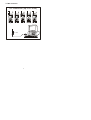
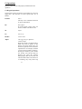
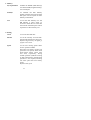
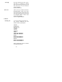
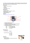
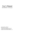
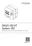
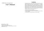
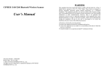
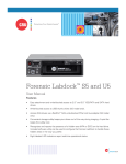
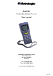
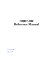
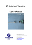
The contents in this manual are copyrighted property of
Syntech Information Co., Ltd.
The information in this manual has been carefully checked
and is believed to be accurate. Syntech Information assumes
no responsibility for any inaccuracies that may be contained
in this document.
The information in this document is subject to change
without prior notice in order to improve reliability, design
and function, and does not represent a commitment on part
of the manufacture.
All right reserved. No part of the contents of this manual
may be reproduced or transmitted in any form or by any
means without prior written permission of Syntech
Information Co., Ltd.
i
Table of Content
1. Introduction....................................................1
2. General Features and Characteristics ..............2
2.1 Electrical ..............................................2
2.2 Environmental ......................................2
2.3 Physical ................................................2
2.4 CPU .....................................................2
2.5 Memory................................................3
2.6 Scanner.................................................3
2.7 Display .................................................3
2.8 Keypad .................................................4
2.9 Indicator ...............................................4
2.10 Communication ..................................4
2.11 Programming Language ......................4
2.12 Accessories.........................................4
3. Hardware Configuration .................................5
3.1 Front, Back and Side View....................5
3.2 RS-232 connection & IrDA connection.6
3.3 RF connection.......................................7
4. Software Organization....................................8
4.1 Kernel module ......................................8
4.2 System module (the operating system)..8
4.3 Application module ..............................9
4.4 Build your own application.................10
5. Operations.................................................... 11
5.1 Keypad operations .............................. 11
5.2 Application mode ...............................12
5.3 System mode ......................................12
5.4 Kernel mode .......................................16
6. Troubleshooting ...........................................17
ii
1. Introduction
The CPT-711 is a compact, light-weighted, high
performance data terminal designed for all-day,
everyday use. It is powered by two AAA size
batteries and supported by a rich set of
development tools, including a Windows-based
application generator, “C” and “Basic” compilers.
It uses a brightly lit, easy-to-read 128x64 graphic
dots FSTN LCD with back-light and adjustable
contrast settings to allow clear reading regardless
of the ambient light. With its integrated
Laser/CCD barcode scanning unit and built-in
RS-232 and IrDA port, the CPT-711 is ideal for
inventory control, document tracking, shop floor
management, asset tracking, warehousing and
distribution operations.
1
2. General Features and Characteristics
Basic characteristics of the CPT-711 Portable Data Terminal
are listed below,
2.1 Electrical
Ÿ
Ÿ
Ÿ
Operation battery : two AAA size disposable or
rechargeable batteries
Backup battery : 3.0V, 7.0mAh, rechargeable
Lithium battery for SRAM & calendar
Working time: over 100 hours and more than 80,000
readings (with its CPU in low speed mode and 1
reading every 5 seconds).
2.2 Environmental
Ÿ
Ÿ
Ÿ
Ÿ
Ÿ
Ÿ
Humidity (operating): non-condensed 10% to 90%
Humidity (storage): non-condensed 5% to 95%
Temperature (operating): -20 to 60 °C
Temperature (storage): -30 to 70 °C
EMC regulation: FCC class A, CE and C-Tick
approved
Shock resistance: 1.2m drop onto concrete
2.3 Physical
Ÿ
Ÿ
Ÿ
Ÿ
Dimensions: 145mm (L) x 63mm (W) x 33.5mm (H)
Weight: 180g (including batteries)
Color: Dark gray
Material: ABS
2.4 CPU
Ÿ
Ÿ
Toshiba 16-bit CMOS type CPU
Dual clock, can be switched to Low Clock to save
power (refer to the speed setting in section 5.3).
2
2.5 Memory
Program memory
Ÿ
1 M Bytes flash memory is used to store the program
code, font, constant data, and so on.
Data memory
Ÿ
1 M Bytes SRAM.
2.6 Scanner
The CPT-711 Portable Data Terminal can be equipped with
Laser or Long Range CCD scanners. Detail specifications
are as following:
CPT-711L (Laser)
Ÿ
Ÿ
Ÿ
Ÿ
Ÿ
Light source: visible Laser diode operating at 670¡ Ó
15nm
Scan rate: 36¡ Ó
3 scans per second
Scan angle: 42¢ Xnominal
Minimum print contrast: 20% absolute dark/light
reflectance at 670nm
Depth of field: 5 ~ 95 cm, depends on barcode
resolution
CPT-711C (CCD)
Ÿ
Resolution: 0.15mm ~ 1.00mm
Ÿ
Depth of field: 20cm
Ÿ
Width of field: 45mm ~ 124mm
Ÿ
Scan rate: 100 scans/sec
Ÿ
Ambient Light Rejection:
1200 lux (Direct Sun-light)
2500 lux (Fluorescent Light)
2.7 Display
Ÿ
128x64 graphic dots FSTN LCD display with LED
back-light
3
2.8 Keypad
Ÿ
21 rubber keys, including alphanumeric keys, arrow
keys, function keys, and scan trigger key.
2.9 Indicator
Buzzer
Ÿ
Software programmable audio indicator, 1KHz to
4KHz, low power transducer type.
LED
Ÿ
Programmable, dual-color (green and red) LED for
status indication.
2.10 Communication
Three kinds of communication are provided: standard RS232, Infrared, and RF.
Ÿ
Ÿ
Ÿ
RS-232: Transmission speed up to 115200bps
Infrared: standard IrDA 1.0 and high speed IR.
Transmission speed up to 115200bps
Distance: 5 to 100 cm
View angle: 30 degrees
RF: Transmission rate up to 9600bps
Distance: up to 100 m
2.11 Programming Language
"C", "BASIC", and a Windows-based Application Generator
2.12 Accessories
Ÿ
Ÿ
Ÿ
Ÿ
RS-232 cable
High speed IR Transceiver
Cradle
RF base station
4
3. Hardware Configuration
3.1 Front, Back and Side View
63mm
IrDA
33.5mm
711
LED
Indicator
Trigger
7 ABC
8D E F
9G HI
4
5
6 PQR
1
2
3Y Z *
ESC
RS-232
side view
Battery
front view
5
back view
3.2 RS-232 connection & IrDA connection
RS-232 & IrDA connection
IrDA connection
RS-232 port
IrDA port
IrDA Transceiver
30 o
5~100cm
711
7 ABC
8DEF
9G
4
5
6 PQR
1
2
RS-232 port
HI
3YZ
*
RS-232 port
ESC
AAA Battery*2
RS-232 connection
6
3.3 RF connection
RF connection (up to 32 units)
711
711
711
711
711
8D E F
9G HI
7 ABC
8DEF
9 G HI
7 ABC
8D EF
9G HI
7 ABC
8DEF
9G H I
7 ABC
8DEF
4
5
6 PQR
4
5
6 PQR
4
5
6 PQR
4
5
6PQR
4
5
1
2
3YZ *
1
2
3YZ*
1
2
3YZ *
1
2
3Y Z *
1
2
7 ABC
ESC
ESC
ESC
ESC
RF Base
7
9G HI
6PQR
3Y Z*
ESC
4. Software Organization
The CPT-711 Portable Data Terminal system software
consists of three modules: the kernel module, the system
module and the application module.
4.1 Kernel module
Kernel module is the innermost core of the system. It has the
highest security and is always protected by the system. Only
the failure of flash memory or improperly power off during
system restart after updating kernel will the kernel be
destroyed. The kernel module ensures that user can always
download their own program even the operating system was
crashed by user’s program. It provides the following
services:
Ÿ
Ÿ
Ÿ
Program download
Update kernel
Test & Calibrate
For detail operations, please refer to section 5.4.
4.2 System module (the operating system)
The system module provides the following system services
Ÿ
Ÿ
Ÿ
Ÿ
Ÿ
Ÿ
Ÿ
Memory
Setting
Reader
Battery
Test
Download
Version
For detail operations, please refer to section 5.3.
8
4.3 Application module
The Application module runs on top of the System module.
The CPT-711 Portable Data Terminal is preloaded with an
application module that runs upon powering the unit up. The
following menu will be shown:
Ÿ
Ÿ
Ÿ
Ÿ
Execute
Clear Data
Transmit Data
Download Settings
The arrow keys can be used to select the menu item, and
execute it by pressing the ENTER key. The function and
meaning of each item are as follows:
Execute
Start the data collection process.
A new screen appears after Execute is
selected and the ENTER key is pressed,
showing the following two prompts:
Item:
Qty:
Data can be input from keypad or barcode
reader. Pressing the ENTER key after the
Quantity has been entered will save the
data and the system will show the same
prompts until the ESC key is pressed,
which will bring back the main menu.
Clear Data
To clear all the transaction data.
A submenu will be shown asking to
confirm this action. Once executed, the
transaction data will be lost and can not be
retrieved. To abort this operation, No must
be selected when asked to confirm the
operation or by pressing the ESC key to go
back to the main menu.
9
Transmit Data To upload transaction data to the host PC.
There are three ways to transmit the data:
via RS-232 or Infrared or standard IrDA.
Note: terminal COM port settings should
match the host PC settings.
Download Settings To download the menus and form
prompts for the data collection process.
The settings should be configured in the
Application Generator, then downloaded
to the terminal. The Application
Generator allows to define menus and
data input forms. For detail operation,
please refer to the Application Generator's
Operation Guide.
4.4 Build your own application module
There are three software tools available for developing
application programs.
1.
2.
3.
The Application Generator
The “BASIC” Compiler
The “C” Compiler
For more information, please contact CipherLab USA or
Syntech Information Co., Ltd.
10
5. Operations
Batteries must be fresh and properly loaded before start
operation.
5.1 Keypad operations
The keypad of CPT-711consists of 20 rubber keys and one
trigger key. The functions of some special keys are as
follows:
ENTER
Enter.
This key is for command execution
or input confirmation.
BS
Back Space.
If pressed down longer than one
second, a clear code will be sent.
SP
Space.
UP
Cursor up.
DOWN
Cursor down.
Alpha
The toggle key for Alphabet /
Numeral input.
When the system is in alpha-mode, a
small icon will be shown on the
display, and each numeral key can
be used to generate one of the three
capital letters. For example, numeral
7 can be used to produce A, B or C.
Pressing the same key twice within
one second, will call the letter B.
Pressing the same key without
halting longer than one second, will
cause the three letters to be shown in
a circulating way. Only when stop
11
pressing the key for longer than one
second or pressing another key, will
the system send the real key code to
the application program.
FN
The function key.
This key can not be activated alone,
it must be pressed with one numeral
key at the same time. For example,
FN + 1 generates function #1, FN +
2 generates function #2, etc (up to 9
functions). Also, this key can be
combined with the UP/DOWN
arrow keys to adjust the contrast of
the LCD. And when this key is
combined with the ENTER key, it
will turn ON/OFF the LCD backlit.
ESC
Escape.
Usually this key is used to exit
current operation.
POWER
Power On/Off.
To prevent a faulty push, it needs
about 1.5 sec continuous pressing to
turn On/Off the power.
5.2 Application mode
This is the default operation mode when turning on the
power. The operation depends on the application module.
Please refer to section 4.4.
5.3 System mode
When pressing the 7, 9 and POWER keys simultaneously, the
system will enter the System Mode with which provides the
following services:
12
1. Memory
Size Information
Includes the SRAM (Data memory)
size and FLASH (Program memory)
size in kilobytes.
Initialize
To initialize the data memory
(RAM). Note that the contents of the
data space will be wiped out after
memory initialization.
Test
To test the data memory. For 256
KB SRAM, it takes about 15
seconds to finish the test. Note that
the contents of the data space will be
wiped out too after memory test.
2. Setting
Clock
To set new date and time.
Backlit
To set the intensity of LCD backlight and the duration for staying on.
Default: High intensity, the lights go
off after 20 seconds.
Speed
To set CPU running speed. There
are five speeds available:
Full speed, 1/2 speed, 1/4 speed, 1/8
speed and 1/16 speed; which need
about 39mA, 22mA, 12mA, 7mA
and 5mA, respectively, during
normal operation (without scanning
or data transmission). If high-speed
operation is not required, selecting
low CPU speed will save battery
power.
Default: Full speed
13
Auto Off
Set time threshold for auto poweroff when no operation is taking
place during that specified period. If
this value is set to zero, this function
will be disabled.
Default: 10 minutes
Power On
There are two possible selections:
Program Resume, which starts from
the program being used during the
last session before the last power-off;
and Program Restart, which starts
with a new program.
Default: Program Resume
3. Reader
Reading test
To test the reading performance of
the scanner. Following are the
default enabled symbologies:
Code 39
Industrial 25
Interleave 25
Codabar
Code 93
Code 128
UPCE
UPCE with ADDON 2
UPCE with ADDON 5
EAN8
EAN8 with ADDON 2
EAN8 with ADDON 5
EAN13
EAN13 with ADDON 2
EAN13 with ADDON 5
Other symbologies, must be enabled
through programming.
14
4. Battery
Main
Show voltage of the main battery
power. If the main battery voltage is
low, a battery icon (power-low
indicator) will be shown on the LCD
screen. The available power will be
less than 25% of fresh batteries, The
terminal will continue to work
normally for a short period of time.
Backup
Show voltage of the backup battery.
5. Test
Buzzer
To test the buzzer with different
Frequency/Duration. Press ENTER
key to start / stop the test.
LCD & LED
To test LCD display and LED
indicator. Press ENTER key to start /
stop the test.
KBD
To test the rubber keys.
Press a key and the result will be
shown on the LCD display. Note
that the FN key should be used in
conjunction with numeral keys.
6. Download
RS-232
To download the user program via
RS-232 port. The transmission
speed can be up to 115200 bps.
Docking
To download the user program via
communication cradle (charger).
The transmission speed can be up to
115200 bps.
15
IR
To download the user program via
high speed IR transceiver. The
transmission speed can be up to
115200 bps.
IrDA
To download the user program via
standard IrDA. The transmission
speed can be up to 115200 bps.
7. Version
Version Info
To show version information,
including
Hardware
version,
Firmware version, Serial Number
and Manufacturing Date.
5.4 Kernel mode
Press the 7, 9 and POWER keys simultaneously to enter the
System mode, then power off and press 1, 7 and POWER key
simultaneously to enter the kernel mode which provides the
following services:
Program download
To download user program. The
download procedure is same as
download program in system mode.
Please refer to the above section.
Update kernel
To
update
system
kernel.
Sometimes the kernel might be
changed for improving performance
or other reasons. This function
allows you to keep the kernel
updated. The update procedure is
same as download user program, but
note that after updating the kernel,
please do not power off until the
system restart itself.
16
Test & Calibrate
To perform a burn-in test and fine
tuning the system clock. This
function is for manufacture purpose
only.
6. Troubleshooting
a)
Does not power up after pressing POWER key.
Ø
b)
c)
Does not power up after changing batteries.
Ø
Check if the batteries are properly installed with
battery cap firmly closed.
Ø
If problem persists, call for service.
Battery-low indicator is on,
Ø
d)
e)
Change the batteries.
Change the batteries.
Cannot download application program from the host
to the CPT-711 Portable Data Terminal or vice versa,
via RS-232 port.
Ø
Check if the RS-232 cable is plugged tightly,
then,
Ø
Check if host communication parameters (COM
port, baud rate, data bits, parity, stop bit) match
the CPT-711 Portable Data Terminal's.
Cannot download application program from the host
to the CPT-711 Portable Data Terminal or vice versa,
via IrDA port.
Ø
Check if the IrDA transceiver tightly connected
to host's COM port, then
17
Ø
Ø
f)
Keypad does not work properly,
Ø
Ø
Ø
Ø
g)
Turn off the power then press the 7, 9 and
POWER keys simultaneously to enter the kernel
mode operation.
From the system menu, select the Test and then
its sub-item KBD.
Perform the key-in test.
If problem persists, call for service.
Scanner does not scan,
Ø
Ø
Ø
h)
Check if host communication parameters (COM
port, baud rate, data bits, parity, stop bit) matched
portable's.
Check if the CPT-711 Portable Data Terminal is
properly positioned within the reading range:
(5 to 100cm, 30 degree solid angle) of the IrDA
transceiver.
Check if symbologies used are enabled, or
Check if battery-low indicator is shown on the
LCD display. If yes, change the batteries.
If problem persists, call for service.
Abnormal responses,
Ø
Ø
Ø
Ø
Open the battery cap and re-load the batteries.
Enter system menu by pressing 7, 9 and POWER
keys simultaneously.
Check if the CPT-711 Portable Data Terminal
can have a correct response by performing
entering data.
If problem persists, call for service.
18