1
Owner’s Manual
VIVARO
Operation, Safety and Maintenance
Reproduction or translation, in whole or in parts,
is not permitted without prior written consent from
Vauxhall Motors Ltd.
All rights as understood under the copyright laws are explicitly
reserved by Vauxhall Motors Ltd.
All information, illustrations and specifications contained in this
manual are based on the latest production information
available at the time of publication.
The right is reserved to make changes at any time without
notice.
Edition: January 2007.
TS 1545-B-07
V I VA R O
©Copyright by Vauxhall Motors Ltd., England.
VAUXHALL Vivaro
Operation, Safety, Maintenance
-2
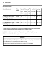
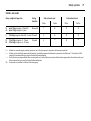
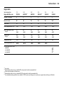
Data specific to your vehicle
Please enter your vehicle’s data here to keep it easily accessible.
This information is available under the section "Technical data" as well as on the identification plate.
Fuel
Designation
Engine oil
Grade
Viscosity
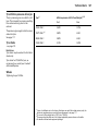
Tyre inflation pressure
Tyre size
with up to 4 persons
with full load
Summer tyres
Front
Rear
Front
Rear
Winter tyres
Front
Rear
front
Rear
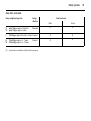
Weights
Permissible Gross Vehicle Weight
–
EC kerb weight
=
Loading
-1
Your Vivaro
Make use of the Owner's Manual:
Your vehicle represents an intelligent
synthesis of advanced technology,
outstanding safety, environmental
compatibility and economy.
z Its "In Brief" section will give you an initial
overview.
z The table of contents at the start of the
Owner’s Manual and in each individual
chapter will help you find your way.
z Its index will help you find what you
want.
z It will familiarise you with the
sophisticated technology.
z It will increase your pleasure in your
vehicle.
z It will help you to handle your vehicle
expertly.
It now lies with you to drive your vehicle
safely and to see it performs perfectly. This
Owner's Manual provides you with all the
necessary information to that end.
Make sure your passengers are aware of
the possible risk of accident and injury
which may result from improper use of the
vehicle.
You must always comply with the laws of
the country in which you are travelling.
These could differ from the information in
this Owner’s Manual.
The Owner's Manual should always be kept
in the vehicle: ready to hand in the glove
compartment.
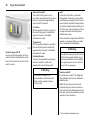
The Owner’s Manual is designed to be
clearly laid-out and easily understood.
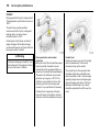
This symbol signifies:
6 Continue reading on next page.
3 The asterisk signifies equipment not
fitted to all vehicles (model variants,
engine options, models specific to one
country, optional equipment, Genuine
Vauxhall Parts and Accessories).
9 Warning
9 Warning is used to mark text
regarding possible risks of accident or
injury. Failure to follow the instructions
could lead to injury or loss of life. Inform
vehicle passengers accordingly.
Yellow arrows in the illustrations serve as
points of reference or indicate some action
to be performed.
Black arrows in the illustrations indicate a
reaction or a second action to be
performed.
Thank you for choosing a Vauxhall. We
wish you many hours of pleasurable
driving.
Your Vauxhall Team
Contents
Commitment to customer
satisfaction:
Our aim: to keep you happy with your
vehicle. All Vauxhall Authorised Repairers
offer first class service at competitive
prices. Experienced, factory-trained
technicians work according to factory
instructions. Your Authorised Repairer can
supply you with GENUINE VAUXHALLAPPROVED PARTS, which have undergone
stringent quality and precision checks, and
of course useful and attractive
VAUXHALL-APPROVED ACCESSORIES.
Our name is your guarantee!
For details of the
Vauxhall Authorised Repairer Network
please ring this number; 0845 090 2044
In brief ......................................................... 2
Instruments .............................................. 20
Keys, doors, bonnet ................................ 37
Seats, interior........................................... 47
Safety systems......................................... 56
Lighting .................................................... 75
Windows.................................................. 79
Heating, ventilation ................................ 81
Tecshift.................................................... 89
Driving hints............................................. 95
Save fuel, protect the environment ....... 97
Fuel consumption, fuel, refuelling.......... 99
Catalytic converter,
exhaust emissions ............................ 102
Drive control systems ........................... 106
Dropside body ....................................... 109
Brakes..................................................... 113
Wheels, tyres.......................................... 117
Roof rack, caravan and trailer towing 122
Self-help ................................................ 125
If you have a problem .......................... 142
Service plan, maintenance ................... 144
Vehicle care ........................................... 157
Technical data ..................................... 161
Index....................................................... 174
2
In brief
In brief
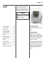
Key numbers, Code numbers
Remove key number from key.
The key number is given in the vehicle
papers and in the Car Pass 3.
Immobilizer, radio 3: the code numbers are
given in the Car Pass and Radio Pass
respectively.
Do not keep the Car Pass and Radio Pass in
the vehicle.
6 Further information - see pages 37, 38.
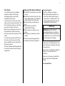
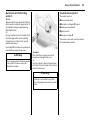
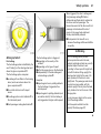
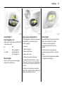
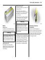
Unlocking the vehicle:
Direct remote control unit 3
towards vehicle,
press button c,
pull door handle
Seat adjustment 3:
Pull handle, slide seat,
release handle,
allow seat to audibly latch into
position
The doors are unlocked.
Never adjust the driver’s seat whilst driving.
It could move in an uncontrolled manner
when the handle has been pulled.
To unlock mechanically: insert key and turn
in driver’s door lock and pull door handle.
To lock doors from inside, press central
locking button 3 located on the lower
dashboard.
6 Door locks - see page 37,
electronic immobilizer - see page 38,
remote control - see page 39,
central locking system - see page 41,
anti-theft locking system - see page 43,
Vauxhall alarm system - see page 43.
9 Warning
Important: Do not sit nearer than 10
inches (25cm) from the steering wheel, to
permit safe airbag deployment.
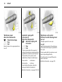
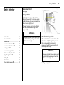
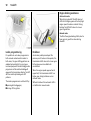
In brief
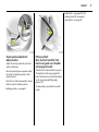
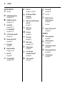
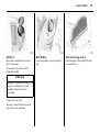
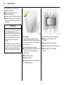
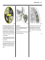
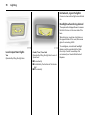
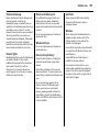
Adjusting the seat back:
Pull release lever
Adjusting the lumbar support 3:
Turn handwheel
Move seat back to suit seating position, it
will lock in position when the lever is
released.
Adjust lumbar support to suit personal
requirements.
Do not lean on seat backrest whilst
adjusting it.
3
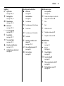
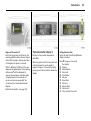
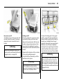
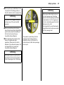
Adjusting arm rest support 3:
Adjust arm rest support to suit personal
requirements.
z Raise armrest in increments to desired
height.
z To reposition, fully raise armrest before
lowering.
4
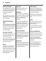
In brief
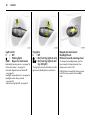
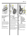
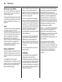
9 Warning
Disregard of these instructions may lead
to injuries or endanger life. Vehicle
passengers should be informed
accordingly.
6 Further information - see page 47.
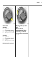
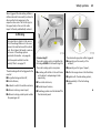
Adjusting seat height 3:
Pull lever at side
Lift lever and remove weight from seat to
raise it or press down on seat with body
weight to lower it.
Never adjust the driver’s seat whilst driving.
It could move in an uncontrolled manner
when the lever has been pulled.
6 Seat position – see page 47.
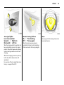
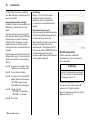
Adjusting head restraint height:
hold firmly and adjust height,
then release
6 Head restraint position – see page 47,
further information, removal – see page 48.
In brief
6 Seat belts – see pages 57 to 59,
airbag systems 3 – see page 61,
seat position – see page 47.
Steering wheel adjustment:
Adjust position
Adjust the steering wheel only when the
vehicle is stationary.
Move the unlocking lever upwards, adjust
the wheel to the desired position, then
release the lever.
Push the lever firmly downwards to ensure
that the wheel is locked in position.
6 Airbag systems - see page 61.
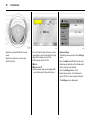
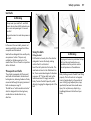
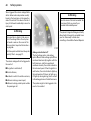
Fitting seat belt:
Draw seat belt smoothly from
inertia reel, guide over shoulder
and engage in buckle
The belt must not be twisted at any point.
The lap belt must lie snugly against the
body. The backrest must not be tilted back
too far (recommended tilting angle
approx. 25°).
To release belt, press red button on belt
buckle.
5
6
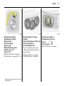
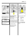
In brief
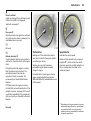
Turn switch to right: switch operates righthand mirror.
Switch in central position: mirror
adjustment is off.
The lower aspherical mirrors are not
adjustable.
Adjust interior 3 and exterior
mirrors:
Swivel to appropriate position
Electrically adjustable exterior
mirrors 3:
Switch in door panel
Move lever on underside of interior mirror
housing to reduce dazzle at night.
Operational with the ignition on or off.
6 Further information - see page 74.
Turn switch to left: switch operates lefthand mirror.
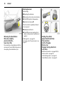
In brief
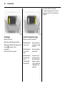
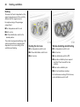
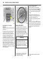
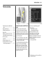
Starter switch:
Diesel engine
St =
Ignition off
A =
Steering unlocked, ignition off
M =
Ignition on: preheat (page 17)
D =
Start - (transmission in neutral)
Petrol engine
St =
Ignition off
A =
Steering unlocked, ignition off
M =
Ignition on
D =
Start - (transmission in neutral)
6 Electronic immobilizer - see page 38.
Releasing the steering column
lock:
To release the lock,
move steering wheel slightly
and turn key to position ‘A’
6 Remove key and lock steering wheel - see
page 18.
7
8
In brief
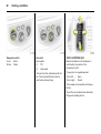
In brief
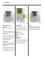
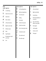
Page
1
Page
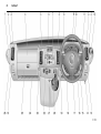
Drink holder ....................................... 55
13 Coin tray
2
Door window defroster vent............. 83
14 Bonnet release lever ......................... 46
3
Side ventilation jets........................... 83
15 Starter switch ...................................... 7
4
Passenger airbag 3 .......................... 61
5
Centre ventilation jets....................... 82
6
Triple information display 3 ............ 29
Colour information display 3........... 31
16 Switches for
headlight range adjustment ............ 76
ESP
(Electronic Stability Program) 3 .... 106
Parking distance sensor 3 ............. 107
7
Infotainment system 3 ..................... 35
Electronic tachograph 3 .................. 36
8
Lever for
Parking lights, headlights flash,
fog lights, dipped and main beam 12
turn signal lights................................ 13
9
Driver’s airbag .................................. 61
Horn ................................................... 13
10 Instruments........................................ 20
11 Lever for windscreen wiper
and wash system ............................. 14
Trip computer 3................................ 26
12 Ashtray ............................................. 55
17 Steering wheel adjustment lever ....... 5
18 Infotainment controls 3 .................. 35
19 Cigarette lighter................................ 54
20 Switches for
central locking 3............................... 41
heated rear window 3...................... 87
Tecshift 3 winter and laden
programme ....................................... 91
21 Hazard warning switch .................... 13
22 Heating and ventilation controls .... 81
Rear air conditioning 3 .................... 86
23 Utility hook
24 Storage tray
25 Glove compartment
26 Fuse box .......................................... 137
9
10
In brief
Control indicators
Ü
Not used
9
Headlight dipped beam:
see pages 12, 75.
P
Headlight main beam:
see pages 12, 75.
r
Fog tail light:
see pages 12, 77.
>
Front fog lights 3:
see pages 12, 77.
u
Anti-lock brake system 3:
see page 115.
8
C
o
Diesel particle filter 3:
see page 104.
Stop engine:
see page 21.
Engine immobiliser:
see pages 21, 38.
A
Service 3:
see page 21.
O
Turn signal lights:
see pages 13, 76.
Y
Fuel level:
see pages 21, 100, 163.
U
Door open 3:
see pages 23.
v
ESP (Electronic Stability
Program) 3:
see page 106.
U
Not used
Z
D
Engine electronics/Preheating
system 3:
see page 17.
Engine electronics,
Exhaust emissions:
see page 23.
B
Not used
E
Engine stop:
see page 21.
F
p
Alternator:
see page 22.
Engine oil life monitor 3:
see page 29.
Tecshift 3
I
Oil pressure:
see page 22.
R
Brake system:
see pages 22, 151.
v
Airbag systems:
see page 61.
H
Front passenger
airbag deactivation 3:
see page 65.
X
Driver’s seat belt:
see page 57.
V
Winter programme:
see page 91.
kg
Laden programme:
see page 92.
W
Transmission electronics:
see page 94.
T
Brake pedal application:
see page 89.
A
Automatic mode:
see page 90.
In brief
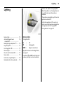
Lighting
7
Light switch:
see pages 12, 75.
0
Parking lights:
see pages 12, 75.
9
Dipped beam:
see pages 12, 75.
P
Main beam:
see pages 12, 75.
>
Front fog lights 3:
see pages 12, 77.
Heating and ventilation
x
Windscreen wiper
Fan switch:
see page 82.
Lever positions:
see page 14,
Air distribution:
see page 81,
K
Timed interval wipe or automatic
wiping with rain sensor 3
M
to head area
1
Slow
L
to head area and to foot area
2
Fast
K
to foot area
n
Windscreen wash
J
to head area and to demister
e
Tailgate window wiper 3
Tailgate window wash 3
r
Fog tail light:
see pages 12, 77.
V
to demister
f
O
Turn signal lights:
see pages 13, 21.
Ü
Miscellaneous
¨
j
Hazard warning flashers:
see page 13, 76.
Heated rear windows and
mirrors 3:
see pages 17, 87.
Horn:
see page 13.
A.C
Air conditioning system 3:
see page 85.
/
Headlight range adjustment:
see page 76.
Bonnet:
see page 46.
4
Air circulation:
see page 85.
)
Cigarette lighter:
see page 54.
e/U
Central locking 3:
see page 41.
:
Glove compartment cooler 3:
see page 86.
E
Parking distance sensor 3:
see page 107.
?
11
12
In brief
Light switch:
7
= Off
0
= Parking lights
9 P = Dipped or main beam
6 Headlight warning device - see page 18,
further information - see page 75,
Automatic dipped beam activation 3
- see page 76,
headlight range adjustment - see page 76,
headlights when driving abroad
- see page 78,
daytime running lights 3 - see page 75.
Fog lights:
7
= Off
> = On (front fog lights 3 only)
>r = On (front fog lights 3 and
fog tail light)
The fog lights will only illuminate when the
ignition and headlights are switched on.
Dipped and main beam:
Headlight flash:
Pull lever towards steering wheel
To change the headlight beam, pull the
lever towards the steering wheel, then
release when a click is felt.
Pulling the lever towards the steering wheel
to the first stop operates the headlight
flash.
In brief
Turn signal lights:
Lever in rest position
Upwards
= Right turn
Downwards = Left turn
When the steering wheel is turned back, the
lever automatically returns to its original
position. This will not happen when making
a minor steering manoeuvre such as lane
changing.
When lane changing, move lever part way
to first stop. When released, lever will
spring back.
For operation of the turn signal lights when
towing - see pages 20 and 122.
Hazard warning flashers:
On = Press button ¨
Off = Press ¨ again
When the hazard warning system is
actuated, the button's control indicators
flash in unison with the turn signal lights.
13
Horn:
Press any part of the steering wheel centre
to activate the horn.
14
In brief
Windscreen wiper:
Move lever downwards
K = Timed interval wipe
1 = Slow
2 = Fast
Return the lever to its original position to
turn off.
Automatic wiping with
rain sensor 3:
Move lever downwards
K = Automatic wiping with
rain sensor
1 = Slow
2 = Fast
The rain sensor detects the amount of
water on the windscreen and automatically
regulates the windscreen wiper frequency.
The sensitivity of the system can be
adjusted by rotating the variable wipe:
Less sensitive
= rotate down
More sensitve
= rotate up
Upon starting the engine, automatic
wiping will need to be reselected.
6 Further information - see pages 153, 158.
Windscreen wash system:
Pull lever towards steering wheel
Short pull
The wiper operates for one cycle.
Long pull
Wash fluid is sprayed onto the windscreen,
at the same time the wiper is operated for
four cycles.
Check regularly that the windscreen wash
system is operating efficiently.
On vehicles with rain sensor 3, keep the
sensor area clean.
6 Further information - see page 153.
In brief
Back door and tailgate window
wash wipe system 3:
Rotate switch
0
= Off
e
= Wiper
f
= Wash
Wash fluid is sprayed onto the window
when the lever is moved to the second
position. The switch is spring loaded and
will return to the ’wiper’ position when
released.
Check regularly that the window wash
system is operating efficiently.
6 Further information - see page 153.
Manual transmission:
o
= Neutral
1 to 5/6= 1st to 5th or 6th 3 gear
R
= Reverse gear
When shifting up from 4th to 5th gear,
pressure must be exerted towards the right
at the beginning of the shift operation.
When shifting from 5th to 4th gear, do not
exert any force towards the left.
Reverse gear: with vehicle stationary,
declutch, pull up collar and move shift lever
to the left against resistance.
If the gear does not engage: with lever in
neutral, release clutch pedal and depress
again, then repeat gear selection.
15
Tecshift 3:
N
= Neutral
o
= Centre position
= Shift to lower gear
+
= Shift to higher gear
A/M = Switch between
automatic or manual
mode
R
= Reverse
The selector lever must be moved in the
appropriate direction as far as it will go.
Upon release, it automatically returns to
the centre position. Pay heed to the
gear / mode indicator in the transmission
display.
6 Further information - see page 89.
16
In brief
Before driving check:
z Tyre pressures and condition.
z Engine oil level and fluid levels in engine
compartment (see pages 145 to 148).
z All windows, mirrors, exterior lighting
and number plates free from dirt, snow
and ice and operational.
z Objects are securely located and will not
be thrown forward in the event of
sudden braking.
z Seats, seat belts and mirrors correctly
adjusted.
z Brake operation.
Exhaust gases are poisonous
Exhaust gases contain carbon monoxide,
which is extremely poisonous but has no
odour or colour.
Therefore, never inhale exhaust gases, and
never run the engine in an enclosed space.
You should also avoid driving with the
doors open, as exhaust gases could enter
the passenger compartment.
6 Exhaust gas - see page 105.
Starting, petrol engine:
Transmission in neutral
Depress clutch
Do not accelerate
Turn key to D
The increased engine speed automatically
returns to normal idling speed as the
engine temperature rises.
6 Electronic immobilizer - see page 38,
further information - see pages 96, 97, 99.
In brief
Starting, diesel engine:
Transmission in neutral
Depress clutch
Do not accelerate
Turn key to M
When preheating control
indicator goes out 1),
turn key to D
Drying misted-up or iced-up
windows:
Set the temperature switch to red
and fan to position 4,
set air distribution to V
6 Electronic immobilizer - see page 38,
further information - see pages 96, 97, 99.
6 Heating, ventilation - see page 81,
air conditioning system - see page 85.
1)
Preheating system switches on only if outside
temperature is low.
Close centre ventilation jets; open side
ventilation jets and direct them towards
the door windows.
Heated rear windows 3,
heated exterior mirrors 3
= On
Press Ü
Press Ü again = Off
6 Further information - see page 87.
17
18
In brief
Warning buzzers
While driving:
z Operating the indicators.
z Illumination of low fuel control indicator.
z Tecshift 3, high clutch temperature.
z Seat belt not fastened 3.
When the vehicle is parked and driver’s
door is opened:
z Headlights switched on.
Releasing the hand brake:
Raise lever slightly,
press lock button,
lower lever fully
Drive carefully, economically and with the
environment in mind. While driving, do not
do anything that could distract you.
z Tecshift 3: neutral not selected, foot
brake not depressed or handbrake not
applied.
6 Driving hints - see page 95,
Save fuel, protect the environment - see
page 97.
Parking the vehicle:
Apply hand brake firmly
Close windows
Switch off engine
Remove key
Engage steering wheel lock
Lock doors
6 Further information - see pages 38, 96,
remote control - see page 39,
central locking system - see page 41,
Vauxhall alarm system - see page 43.
In brief
Advice when parking:
z Always apply hand brake firmly. Engage
first gear or reverse gear. On slopes
apply the hand brake as far as it will go.
z Turn steering wheel until lock is felt to
engage (anti-theft protection).
z Switch off exterior lights, otherwise the
headlight warning device will sound
when the driver’s door is opened.
z Cooling fans may run on after the engine
has been switched off.
z Do not park vehicle on easily ignitable
surfaces as the hot exhaust system could
cause the surface to ignite.
Service work, maintenance
We recommend that you entrust all work to
your Vauxhall Authorised Repairer, who
can provide you with reliable service and
correctly perform all work according to
factory instructions.
Vauxhall Service - see page 142.
Genuine Vauxhall Parts and
Accessories
We recommend “Genuine Vauxhall Parts
and Accessories” and conversion parts
released expressly for your vehicle type.
These parts have undergone special tests
to establish their reliability, safety and
specific suitability for your vehicle. Despite
continuous market monitoring, we cannot
assess or guarantee these attributes for
other products, even if they have been
granted approval by the relevant
authorities or in some other form.
"Genuine Vauxhall Parts and Accessories"
and conversion parts approved by
Vauxhall can be obtained from your
Vauxhall Authorised Repairer, who can
give advice about permitted technical
changes and correct installation.
9 Warning
Carry out regularly the checks
recommended in this Owner's Manual.
Ensure that your vehicle is serviced at the
service intervals specified in the Service
Booklet. We recommend that you entrust
this work to your Vauxhall Authorised
Repairer.
Have faults remedied without delay!
Consult a workshop. We recommend your
Vauxhall Authorised Repairer. If
necessary, interrupt your journey.
6 Maintenance - see pages 144 to 155.
19
That was a brief overview of the
most important information for
your first drive in your Vivaro.
Your vehicle has still more
instruments and controls,
possibly also optional
equipment.
The remaining chapters of the
Owner’s Manual contain
important information on
operation, safety and
maintenance as well as a
complete index.
20
Instruments
Instruments
Control indicators ...............................
Tachometer.........................................
Speedometer.......................................
Fuel gauge ..........................................
Coolant temperature gauge..............
Multifunction display..........................
Electronic odometer/clock 3..............
Trip computer 3 .................................
Engine oil life monitor 3.....................
Triple information display 3 ..............
Colour information display 3,
selecting functions ...........................
Radio 3................................................
20
23
23
24
24
25
26
26
29
29
31
35
Control indicators
The control indicators described here are
not present in all vehicles. The description
applies to all instrument versions.
Ü
Not used
9
Headlight dipped beam
Lights up when dipped beam is on.
P
Headlight main beam
Lights up when main beam is on and when
headlight flash is operated.
r
Fog tail light
Lights up when the fog tail light is switched
on.
>
Front fog lights 3
Lights up when front fog lights are
switched on.
u
Anti-lock brake system
see page 115.
8
Diesel particle filter 3
Lights up when regeneration of diesel
particle filter is required - see page 104.
F
Not used
Instruments
v
ESP (Electronic Stability Program) 3
see page 106.
F
Engine oil life monitor 3
See page 29.
kg
Tecshift Laden programme 3
Control indicator illuminates in
transmission display when Laden
programme is enabled - see page 92.
T
Tecshift foot brake application 3
see page 89.
W
Tecshift electronics 3
Lights up briefly when ignition is switched
on. Illuminates in transmission display
when fault has occurred - see page 94.
A
Tecshift automatic mode 3
Control indicator illuminates in
transmission display when automatic
mode is selected - see page 90.
V
Tecshift Winter programme 3
Control indicator illuminates in
transmission display when Winter
programme is enabled - see page 91.
O
Turn signal lights
Flashes when turn signal lights are on.
Flashes rapidly: a turn signal bulb has
failed.
An audible warning can be heard when the
turn signal lights are on. When towing a
caravan or trailer, the pitch of the audible
warning changes.
C
Stop engine
If C lights up in conjunction with p, I,
E or R, stop engine immediately and
consult a workshop. We recommend your
Vauxhall Authorised Repairer.
o
Engine immobilizer
If the indicator flashes when the ignition is
on, there is a fault in the immobilizer
system; the engine cannot be started - see
page 38.
A
Service / engine electronics 3
If A lights up in conjunction with u or v,
interrupt your journey. Consult a workshop.
We recommend your Vauxhall Authorised
Repairer.
21
D
Preheating/Fuel filter/Engine electronics
Lights up briefly during engine preheating.
If illuminated constantly it indicates:
z The presence of water in the diesel fuel
filter 3. Drain fuel filter of residual water,
see page 149.
z An electronic system failure, consult a
workshop. We recommend your
Vauxhall Authorised Repairer.
Y
Fuel level
If it lights up: fuel level low, fill up.
Never let the tank become empty!
With diesel engines it is not possible to start
the engine after the tank has been run
empty. The fuel system must be bled first.
22
Instruments
E
I
p
Alternator
Lights up when ignition is switched on.
Goes out after engine is started.
If illuminated during driving:
Engine lubrication may be interrupted,
resulting in damage to the engine and/or
locking of the driving wheels:
If illuminated during driving:
Stop vehicle and switch off engine. The
battery is not being charged and the
engine cooling may be interrupted. The
brake servo unit may cease to be effective.
Interrupt your journey, consult a workshop.
We recommend your Vauxhall Authorised
Repairer.
z Depress clutch.
z Move gear shift lever to neutral.
z Switch off ignition (to position A).
Considerably greater force will be
required for braking and steering.
Engine stop
Will light up in conjunction with C engine
if coolant temperature is too high. Stop
vehicle - consult a workshop. We
recommend your Vauxhall Authorised
Repairer.
Oil pressure
Lights up when ignition is switched on.
Goes out after a short period of time. Can
light up intermittently when idling with hot
engine; must go out when engine speed is
increased.
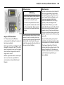
9 Warning
Do not remove key until vehicle has come
to a standstill, otherwise the steering
column lock could engage unexpectedly.
Consult a workshop. We recommend your
Vauxhall Authorised Repairer.
R
Brake system
Lights up when ignition is switched on if
hand brake is applied and/or fluid level for
brake hydraulics is too low.
9 Warning
If it lights up when the hand brake is not
applied: stop vehicle; interrupt your
journey immediately. Consult a
workshop. We recommend your Vauxhall
Authorised Repairer.
6 Further information - see page 113.
v
Airbag 3
see page 61.
H
Front passenger airbag deactivation 3
Lights up when the ignition is switched on
and remains illuminated when the front
passenger airbag has been deactivated.
If H illuminated in conjunction with v or A
consult a workshop. We recommend your
Vauxhall Authorised Repairer.
6 Further information - see page 65.
Instruments
23
X
Driver’s seat belt
Lights up when ignition is switched on and
if driver’s seat belt is not engaged.
Seat belts, see page 57.
U
Door open 3
Operational only when ignition is switched
on. Lights up when driver’s, passenger’s or
side loading doors are open.
U
Not used.
Z
Exhaust emissions 3
Control indicator lights up when ignition is
switched on. Goes out shortly after engine
starts.
If it lights up when the engine is running:
Fault in emission control system. The
permitted emission limits may be
exceeded. Consult a workshop. We
recommend your Vauxhall Authorised
Repairer.
Tachometer
Speedometer
Making use of the tachometer helps to
save fuel; it indicates the engine speed in
revolutions per minute.
Indicates the vehicle speed.
Warning zone on right: maximum
permissible engine speed exceeded,
danger to engine.
Certain vehicle variants feature a speed
regulator 3 1) which restricts the vehicle
maximum speed. As a visible indication of
this, a warning label is located on the
instrument panel.
If possible, drive in each gear in the low
engine speed range (between approx.
2000 and 3000 rpm) and maintain an even
vehicle speed.
If it flashes when the engine is running:
For fault that can lead to destruction of the
catalytic converter, see page 102. Consult
a workshop immediately. We recommend
that you consult your Vauxhall Authorised
Repairer.
B
Not used
1)
Depending on driving environment (e.g. when
descending steep inclines) the vehicle speed
can exceed set limits. In such instances it
remains the driver’s responsibility to adhere to
the specific speed limits.
24
Instruments
For physical reasons, the coolant
temperature gauge shows the coolant
temperature only if the coolant level is
adequate.
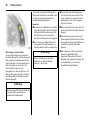
Fuel gauge
Coolant temperature gauge
Display of fuel level:
Display of coolant temperature:
Illumination of bars displays fuel level.
Bars illuminated =
in lower area
When gauge indicates fuel supply low, fuel
warning Y illuminates = fill up.
See page 99.
Never let tank become empty!
Bars illuminated =
up to central
area
Bars illuminated =
into uppermost
zone
or indicator E
illuminates 3
Engine operating
temperature not yet
reached
Normal operating
temperature
Temperature too
high. Stop vehicle,
switch off engine.
Danger to engine.
Check coolant level
immediately. See
page 150.
Instruments
Multifunction display
Transmission display 3
Display of the selected gear and mode with
Tecshift 3.
N
Neutral or idling position.
R
Reverse gear.
A
Automatic mode.
kg Laden programme.
V Winter programme.
T Foot brake application.
W Transmission electronics.
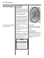
Oil level display 3
The oil level display is correct only if the
vehicle is parked on level ground with a
cold engine. The oil level display will only
be reset if the ignition has been switched
off for more than two minutes.
25
The squares that appear on the display
indicate the level. As the oil level
diminishes, the squares in the display
disappear and are replaced with dashes.
If "oil" appears in the display the oil level
may need topping up. To gain a more
accurate indication of the oil level, press
and hold the reset button - see page 28.
1)
A:
Maximum level
B:
Intermediate level
C:
Minimum level = check and top up
engine oil1)
A illuminates if oil level is too low.
To return to the normal display, press the
reset button again.
Checking and topping up fluids - see page
145.
26
Instruments
Electronic odometer/clock 3
Normal mode:
The odometer and clock are visible.
Reset:
The reset button is located alongside the
speedometer. Press button once to display
the trip odometer.
Press the button and hold, the display will
flash and after 1 second will reset to zero.
Press the button again to return the
odometer to normal mode.
Clock adjust mode:
With the display in normal mode press and
hold the button, and the minutes reading
will begin to increase.
After the button is released the clock will
continue to flash for a further 5 seconds to
enable further adjustments to be made.
Trip computer 3
In addition to the electronic odometer
functions, the trip computer can also
display additional monitored vehicle data;
z
z
z
z
z
z
Fuel used,
Average consumption,
Instantaneous consumption,
Range,
Distance travelled,
Average speed.
Pressing the selection switch located on the
end of the windscreen wash control lever
will cycle through these displays.
Fuel used
Displays the amount of fuel consumed
since the last reset. The measurement can
be restarted at any time – see page 28.
Instruments
Average consumption
Is displayed, taking into consideration the
distance travelled and the fuel used since
the last reset. The measurement can be
restarted at any time - see page 28.
Instantaneous consumption
The value is displayed after reaching a
speed of 15 mph (25 km/h).
27
Range
The range is calculated from the current
contents of the fuel tank and the average
consumption since the last reset
- see page 28.
28
Instruments
Distance travelled
Displays the distance driven since the last
reset. The measurement can be restarted
at any time.
Average speed
The average speed is displayed, since the
last reset. The measurement can be
restarted at any time.
Stoppages in the journey with the ignition
off are not included in the calculations.
Reset current trip computer information
The following trip computer information
can be reset:
z
z
z
z
z
Fuel used,
Average consumption,
Range,
Distance travelled,
Average speed.
To reset the trip computer, select one of its
functions then press and hold the reset
button, the display will flash and after 1
second will reset.
Interruption of power supply
If the power supply has been interrupted or
if the battery voltage has dropped too low,
the values stored in the trip computer will
be lost.
Instruments
Engine oil life monitor 3
Each time the ignition is switched on, the
remaining distance before the next engine
oil and filter change is due may be shown
in the display for approx. 5 seconds.
Within 1 800 miles (3 000 km) of the next
engine oil change being due, the remaining
distance and F will be displayed for
approx. 30 seconds as a reminder. Make
an appointment with a workshop for
service work as soon as possible. We
recommend your Vauxhall Authorised
Repairer.
6 Further information - see page 105.
Triple information display 3
Display for time, outside temperature,
radio/date.
When the ignition is off, the time, date and
outside temperature can be made to
appear for approx. 15 seconds by briefly
pressing one of the two buttons beside the
display.
Setting date and time
Switch off radio. Press Ö and ; beside
display as follows:
Press Ö for approx. 2 seconds:
Day flashes
;: Set day
Ö: Month flashes
;: Set month
Ö: Year flashes
;: Set year
Ö: Hours flash
;: Set hours
Ö: Minutes flash
;: Set minutes
Ö: Clock starts at 0 seconds.
29
30
Instruments
If only the time is to be set, repeatedly
press Ö with display in setting mode until
hours/minutes flash.
Automatic date and time setting 3
Possible in the case of radio reception from
RDS stations1) which broadcast a time
signal.
Automatic setting is carried out once the
radio has been switched on and a RDS time
signal has been received. The setting is
indicated by } in the display. If no time
signal is received, or the time signal is
inaccurate, the date and time must be set
manually.
Deactivating and activating the automatic
setting function (e.g. if an inaccurate time
signal is received from the broadcasting
station):
Press Ö
for approx. 2 seconds; the time
display is now in setting mode.
Press Ö
twice (until year flashes).
Press Ö
for approx. 3 seconds until } in
display flashes and the display
“RDS TIME” appears (years
flash while button is depressed).
Press ;
Press Ö
1)
Display indicates:
RDS TIME 0 = Deactivated
RDS TIME 1 = Activated
three times.
RDS = Radio Data System.
Fault display
Display --.-°C or an F in the display
indicates a fault. Have the cause
eliminated, consult a workshop. We
recommend your Vauxhall Authorised
Repairer.
Interruption of power supply
If the power supply has been interrupted or
if the battery voltage has dropped too low,
the date and time must be reset.
When the battery has been reconnected or
charged, set the date and time as
described under “Setting date and time”.
In the case of radios with RDS 3, the time is
set automatically when the radio is
receiving an RDS station which broadcasts
a time signal (see page 30).
Outside temperature
A fall in temperature is indicated
immediately and a rise in temperature
after a time delay.
9 Warning
Caution: The road surface may already
be icy even though the display indicates
a few degrees above 0 °C.
If the external temperature falls to 3 °C, to
warn of ice on the road the symbol :
appears on the Triple Info display.
When the temperature climbs, the symbol
: goes out above 5 °C.
Instruments
31
Slippery road
-2,5°C
OK
In vehicles with colour information display
3, a warning message appears in the
display as a warning for icy road surfaces.
There is no message below -5 °C
9 Warning
Caution: The road surface may already
be icy even though the display indicates
a few degrees above 0 °C.
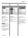
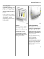
Colour information display 3,
selecting functions
Functions and their menus are depicted in
the information display.
These functions are marked or executed in
the menu display via the cross switch, the
multifunction knob 3 on the Infotainment
System or buttons 3 on the steering wheel.
To select with four-way button:
Select menu items via menus and
with the buttons/four-way button of
the Infotainment system.
Selection with the multifunction knob 3:
Turn
Mark menu items
or commands, select
functions.
Press
Select marked item,
confirm command.
To exit a menu, turn the multifunction
button left or right to Return or Main
and select.
32
Instruments
7
FM AS
[TP]
REG
CDin
MP3
Settings
Time, Date
19,5° 19:36
19:36
Language
�
90.6 MHz
Units
10 . 07 . 2004
Contrast
Day / Night
19,5°
Selection using buttons 3 on steering
wheel:
Select menu options via menus and
with the buttons.
19:36
For each functional area there is a main
page (Main), which is selected at the top
edge of the display (not with the
Infotainment system CD 30):
z Audio
z Navigation 3
Function areas audio and navigation 3
– see Infotainment System Instructions.
6 Ign. logic
System settings
The settings are accessed via the Settings
menu.
Press the Main button 3 (not found on all
Infotainment systems) on the Infotainment
system (call up main display).
Press the Settings button on the
Infotainment system. For Infotainment
system CD 30, no menu may be selected.
The Settings menu is displayed.
Instruments
7
Time, Date
Time
Date
19,5° 19:36
19:36
10 . 07 . 2004
6 Synchron. clock automatical.
7
Settings
19,5° 19:36
7
13 Languages
33
19,5° 19:36
X Deutsch
Time, Date
Language
Deutsch
English
Units
English
Español
Contrast
Español
Dutch
Day / Night
...
French
6 Ign. logic
Italiano
Setting date and time
Select menu item Time, Date, from the
Settings menu.
Language selection
You can select the display language for
some functions.
Select the desired language.
The menu for Time, Date, is displayed.
Select menu item Language from the
Settings menu.
In systems with voice output 3, when the
language setting of the display is changed
the system will ask whether the
announcement language should also be
changed – see Infotainment system
instructions.
Select the menu items required:
Make the desired setting.
Correcting time 3
Some RDS transmitters1) do not send
correct time signals. If the incorrect time is
frequently displayed, deactivate
automatic time synchronisation 3 and set
the time manually.
To correct time with the help of RDS, select
menu item Synchron. clock automatical.
from the Time, Date, menu.
1)
RDS = Radio Data System.
The available languages are displayed.
Selections are indicated by a 6 in front of
the menu item.
34
7
Instruments
Settings
19,5° 19:36
Time, Date
Language
~
Europe-SI
Units
|
|
|
Japan
Contrast
Day / Night
Great Britain
USA
6 Ign. logic
Setting units of measure
You can select which units of measure are
to be used.
Select menu item Units from the Settings
menu.
The available units are displayed.
Select the desired unit.
Selections are indicated by a o in front of
the menu item.
Setting display mode 3
The display can be adapted to light
conditions: Dark coloured text on a light
background or light coloured text on a
dark background.
Select menu item Day / Night from the
Settings menu.
The options are displayed.
Automatic: Adapted based on vehicle
lighting.
Always day design: Dark coloured text on
light background.
Always night design: Light coloured text
on dark background.
Selections are indicated by a o in front
of the menu item.
Ign. logic 3
See Infotainment system instructions.
Ü
19,5° 19:36
00:00:00
Timer
Start
Reset
Options
Stop watch 3
Press BC button on the infotainment
system
The Timer menu is displayed.
To start, select menu item Start.
To reset, select menu item Reset.
Instruments
The stop watch information to be
displayed can be selected via menu
Options 3:
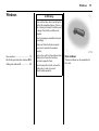
Radio 3
Driving Time excl. Stops
Measurement of the time the vehicle is in
motion. Stationary time is not included.
Vehicle radio reception will differ from that
obtained with domestic radios.
Driving Time incl. Stops
Measurement of the time the vehicle is in
motion. The time the vehicle is stationary
with the key in the ignition switch is
included.
Travel Time
Measurement of the time from manual
activation via Start to manual deactivation
via Reset.
35
The radio is operated as described in the
operating instructions supplied.
As the vehicle antenna is relatively near the
ground, the broadcasting companies
cannot guarantee the same quality of
reception as is obtained with a domestic
radio using an overhead antenna.
z Changes in distance from the transmitter
z Multi-path reception due to reflection
and
z Shadowing
may cause hissing, noise, distortion or loss
of reception altogether.
Steering wheel mounted remote
control 3
Radio and infotainment system functions
can be operated by the buttons mounted
on the steering wheel.
The radio 3 and infotainment system 3 are
operated as described in the respective
operating instructions supplied.
36
Instruments
Infotainment and navigation
systems 3
The systems are operated as described in
the operating instructions supplied.
The navigation system is supplied with a
CD or DVD detailing the local territory.
For additional countries/territories,
separate CD’s or DVD’s are available from
your Vauxhall Authorised Repairer.
Mobile telephones and radio
equipment (CB) 3
Electronic tachograph 3
The tachograph is operated as described
in the operating instructions supplied.
Observe regulations regarding use.
The Vauxhall installation instructions and
the operating guidelines provided by the
telephone manufacturer must be observed
when fitting and operating a mobile
telephone. Failure to do so could invalidate
the vehicle’s operating permit (EU Directive
95/54/EG).
Requirements to ensure trouble-free
operation:
z Professionally installed exterior aerial to
obtain the maximum range possible
z Maximum transmission power 10 W
z Installation of the telephone in a suitable
spot (see note on page 66).
Obtain advice on predetermined
installation locations for the external
antenna and equipment holder and ways
of using devices with transmission power of
more than 10 Watts. We recommend that
you consult your Vauxhall Authorised
Repairer, who will have consoles and
various installation kits and install them in
accordance with regulations.
Use a hands-free attachment if you must
use your phone while driving. Even with a
handsfree attachment, the telephone
could distract you from the traffic situation.
Follow the national regulations of the
country in which you are driving.
9 Warning
When used in the vehicle interior, mobile
telephones and radio equipment (CB)
with integrated antenna may cause
malfunctions in the vehicle electronics.
Mobile telephones and radio equipment
(CB) should only be used with an antenna
fitted on the vehicle exterior.
Keys, doors, bonnet
Keys, doors, bonnet
37
Replacement keys
The key is a constituent of the electronic
immobiliser. Ordering keys from a Vauxhall
Authorised Repairer guarantees problemfree operation of the electronic
immobiliser.
Keep the spare key accessible in a safe
place.
Locks - see page 160.
Door locking and unlocking
Replacement keys ..............................
Door locking and unlocking...............
Child safety lock .................................
Electronic immobilizer ........................
Radio frequency remote control 3....
Central locking system 3 ...................
Mechanical anti-theft locking
system 3 ...........................................
Vauxhall alarm system 3...................
Sliding side doors 3............................
Back doors 3.......................................
Tailgate 3 ...........................................
Bonnet release ....................................
37
37
37
38
39
41
43
43
44
45
45
46
From outside:
Pull the outside handle to open the front
door.
remote control 3 - see page 39,
central locking system 3 - see page 41,
anti-theft locking 3 - see page 43.
From inside:
Pull the inside lever to open the front door.
The door can be locked or unlocked by
pushing the lock button 3 or using the
central locking switch 3 - see page 42.
To prevent the driver from being
inadvertently locked out, the front doors
cannot be locked when they are open.
The tailgate can be opened by pushing
down the tailgate interior release 3 .
6 Further information - see page 2.
Child safety lock
The child safety lock for the sliding side
door 3 is located on its rearward facing
edge.
9 Warning
Use the child safety lock whenever
children are occupying the rear seats 3.
Disregard may lead to injuries or
endanger life. Vehicle passengers should
be informed accordingly.
To engage, turn knob from the vertical
position: anti-clockwise for right hand side
door or clockwise for left hand side door.
Door cannot then be opened from inside.
38
Keys, doors, bonnet
Note
The immobilizer does not lock the doors.
Therefore, after leaving the vehicle, always
lock it and switch on the Vauxhall alarm
system 3.
The Car Pass contains all the vehicle’s data
and therefore must not be kept in the
vehicle.
Have your Car Pass ready to hand when
consulting a Vauxhall Authorised Repairer.
Electronic immobilizer
The system checks whether the vehicle may
be started using the key that has been
inserted. If the key is recognised as
"authorised" the vehicle can be started.
The check is carried out via a transponder
housed in the key.
The electronic immobiliser is automatically
activated when the key is removed from
the ignition switch.
Control indicator for immobilizer
The control indicator lights up when the
ignition is switched on then goes out.
If the control indicator flashes rapidly after
the ignition is switched on, there is a fault in
the immobilizer system.
z Turn ignition off and remove key,
z wait approximately two seconds,
z then repeat starting procedure.
If the control indicator fails to extinguish,
try to start the engine using the spare key.
Obtain assistance from a workshop. We
recommend that you consult your Vauxhall
Authorised Repairer.
Keys, doors, bonnet
39
Central locking system 3
see page 41.
Mechanical anti-theft locking system 3
see page 43.
Vauxhall alarm system 3
see page 43.
Radio frequency remote control 3
The remote control is used to operate the
central locking system 3.
For your convenience we recommend that
the central locking system is always
operated using the remote control unit.
Depending on model the vehicle may use a
remote control with two or three buttons
(selective door locking).
Treat the remote control unit with care; it
should be protected against moisture and
should not be operated unnecessarily.
The remote control has a range of approx.
3 metres. The range may be reduced
owing to shadowing and reflection of the
radio waves. To operate the remote
control, direct the remote control unit at
the vehicle.
40
Keys, doors, bonnet
Note
If the central locking system 3 cannot be
operated with the remote control, this may
be due to the following reasons:
z The remote control is out of range.
z The battery voltage of the remote
control is too low. Change the battery in
the remote control unit.
z The remote control has been operated
too many times in succession outside the
vehicle’s reception range (e.g. at too
great a distance from the vehicle).
The remote control must be
reprogrammed, we recommend your
Vauxhall Authorised Repairer.
z Interference from higher power radio
waves from other sources.
Lock or unlock the doors manually using
the key or central locking switch. Manual
locking does not operate the central
locking system. Have cause of fault
remedied. We recommend that you consult
your Vauxhall Authorised Repairer.
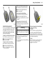
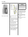
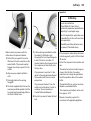
Changing the battery in remote control
unit
Replace the battery in accordance with the
Service Booklet or when the range of the
remote control starts to become reduced.
Two function remote control unit:
Open the battery compartment by
inserting a coin into the slot and twisting.
Ensure the new battery is installed
correctly.
Replace the cover and press until it is fully
engaged.
Selective door locking remote control unit
Open the battery compartment by
removing the screw on the rear cover, then
inserting a coin into the slot and twisting.
Ensure the new battery is installed
correctly.
Replace the cover and press until it is fully
engaged, then replace and secure screw.
Make sure that you dispose of old batteries
in accordance with environmental
protection regulations.
Keys, doors, bonnet
41
To lock - two function remote control:
Press e button on remote control unit:
z Hazard warning lights flash twice.
z Doors are locked.
To lock - selective door locking:
Press e button on remote control unit:
z Hazard warning lights flash twice.
z Passenger compartment doors only are
locked.
Central locking system 3
For front, side and back doors 3, tailgate 3
and fuel filler flap 3. With selective door
locking 3, the passenger compartment
and rear load compartment are locked
and unlocked separately.
To unlock - two function remote control:
Press c button on remote control unit:
z Hazard warning lights flash once.
z Doors are unlocked.
To unlock - selective door locking:
Press c button on remote control unit:
z Hazard warning lights flash once.
z Doors of the passenger compartment
only are unlocked.
Always ensure that the side door 3,
tailgate 3 or back doors are properly
closed before locking the vehicle with the
remote control.
9 Warning
For safety reasons, the vehicle cannot be
locked if the ignition key is in the ignition.
Manually locking or unlocking a door with
the key does not operate the central
locking system.
For manual operation of the fuel filler flap
- see page 101.
Rear load compartment doors/tailgate selective door locking
To unlock
Press G button on remote control unit.
If no door is opened within 30 seconds
(approximately) after the vehicle has been
unlocked by the remote control the vehicle
is re-locked automatically.
To lock
Press G button on remote control unit.
The rear load compartment doors /
tailgate are now locked.
42
Keys, doors, bonnet
Automatic locking 3
The central locking system can be
activated to automatically lock the doors
as soon as a speed of approximately
4 mph (6 km/h) is reached.
To activate
With the ignition switched on, press e on
the central locking switch and hold for
approx. 5 seconds, until audible
confirmation is heard.
Central locking switch 3
Use the central locking switch to lock or
unlock the doors from inside the vehicle.
Press e on the switch to lock or U on the
switch to unlock.
To deactivate
With the ignition switched on, press U on
the central locking switch and hold for
approximately 5 seconds, until audible
confirmation is heard.
Unlocking the door
The doors are unlocked by opening any
door from inside the vehicle or by
operating the central locking switch.
9 Warning
If a rear door is opened, it will
automatically be relocked when the
vehicle reaches a speed of approx.
4 mph (6 km/h).
Fault
In the event of a fault e.g. automatic
locking doesn’t take place, ensure all the
doors have been properly closed. Check to
ensure that the automatic locking function
has not been deactivated inadvertently. If
this is the case, switch the ignition off and
on again and reactivate the system as
described previously.
If the automatic locking function still fails to
operate we recommend that you contact
your Vauxhall Authorised Repairer.
9 Warning
If you decide on having the system active
(with the doors closed) whilst driving, it
may become difficult for those assisting
you in gaining access to your vehicle in
the event of an emergency.
Slam door locks 3
For certain Van models1) the sliding side
door and back door locks are isolated for
added security.
Whilst the front doors are locked and
unlocked using the remote control key in
the normal way, the sliding side door and
back door can only be opened by manual
operation of the vehicle key.
1)
Not available with deadlock option.
Keys, doors, bonnet
Mechanical anti-theft locking
system 3
Vauxhall alarm system 3
To lock:
All doors must be closed; press the e button
on the remote control unit again within 10
seconds after locking. Hazard warning
lights flash 5 times.
-orturn key in driver's door lock towards front
of vehicle again within 10 seconds after
locking, then turn it back to the vertical
position and remove.
z Front and side doors.
Lock buttons 3 on all doors are positioned
such that doors cannot be opened.
9 Warning
Do not use the system if there are people
in the vehicle! The doors cannot be
unlocked from inside.
43
The system monitors:
z Back doors or tailgate 3, bonnet.
z Passenger compartment.
z Ignition switch.
z Siren power supply 3.
The remote control unit is used to operate
the Vauxhall alarm system.
To unlock:
Press c button on remote control unit.
Hazard warning lights flash once.
-orturn key in driver's door lock towards rear
of vehicle, then turn it back to the vertical
position and remove.
9 Warning
Unlocking is not possible in any other
way, so keep spare key to hand in a safe
place!
44
Keys, doors, bonnet
To activate
All doors must be fully closed; press the e
button on the remote control, the turn
signal indicators flash twice. If the turn
signal indicators do not flash on activation,
this may indicate that a door or the bonnet
is not fully closed.
Passenger compartment monitoring
When the anti-theft alarm is activated, the
system automatically monitors the inside
of the vehicle for movement.
To deactivate
Press the c button on the remote control,
the turn signal indicators flash once.
z Press and hold the e button on the
remote control.
z An audible beep will sound to confirm
that the passenger compartment
monitoring function is disabled.
If the alarm has been triggered, the turn
signal indicators will not flash upon
deactivation.
When unlocking the vehicle using the key,
the alarm will sound; to deactivate, insert
the key and switch on the ignition.
Note
The Vauxhall alarm system cannot be
deactivated in any other way so keep a
spare key in a safe place.
Alarm
During a switch-on phase the sensors can
trigger a maximum of 10 times1).
The alarm takes the form of:
z an acoustic signal (horn, 25 seconds)
and
z a visual signal1) (turn signal indicators,
25 seconds).
1)
Varies from country to country on account of
national regulations.
To disable the passenger compartment
monitoring, (for example if an animal is left
in the vehicle):
The disable monitoring function will remain
until the alarm is deactivated or the doors
unlocked.
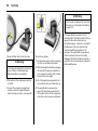
Sliding side doors 3
Alarm back-up system 3
The alarm system has a battery back-up
siren unit which, in the event of its power
supply being disconnected or
disconnection of the vehicle battery, will
sound for approx. 5 minutes on its internal
batteries.
To close the door, slide it fully forwards and
ensure it is fully closed.
If the vehicle battery has to be
disconnected it will be necessary to
deactivate the alarm system.
To stop the siren if activated, reconnect the
vehicle battery and press the rear c button
on remote control unit.
Open the door by pulling the outside
handle, or by pulling the interior lever to
the rear, then sliding the door rearwards.
The door can be locked or unlocked with
the remote control 3, the central locking
switch 3 or by the interior lock switch.
Ensure the side door is closed before
driving the vehicle.
Keys, doors, bonnet
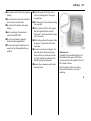
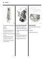
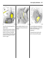
Back doors 3
The doors can be locked or unlocked with
the remote control 3 , the central locking
switch 3, or the key 3.
To open the left-hand back door pull the
outside handle. The door is opened from
inside the vehicle by pulling the interior
handle.
The right-hand rear door is released using
the lever (arrowed).
9 Warning
The rear lights may be obscured if the
rear doors are open and the vehicle is
parked on the roadside. You should
make other road users aware of your
vehicle, by using a warning triangle or
other equipment specified by your
country’s road traffic regulations.
The doors are retained in the 90º position
by locking stays.
To open the doors to 180º or further 3, pull
the door release handles and swing open
to the desired position.
9 Warning
Ensure extended opening doors 3 are
secured when fully opened.
Opened doors may slam closed due to
the force of the wind!
Always close the right-hand door before
the left-hand door.
45
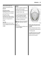
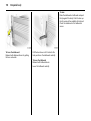
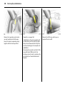
Tailgate 3
To open: press button and lift tailgate to
fully open position.
In very cold climates, the opening
assistance provided by the tailgate
hydraulic struts may be reduced.
The tailgate can be locked or unlocked
with the remote control 3 , the central
locking switch 3.
9 Warning
Ensure there is adequate clearance both
above (at least 2.15 m) and behind when
opening tailgate.
Close tailgate using the interior strap.
Ensure tailgate is fully closed.
46
Keys, doors, bonnet
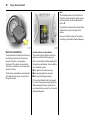
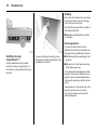
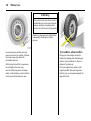
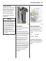
Bonnet release
To open the bonnet, pull the release lever
located on the left-hand side below the
instrument panel. The bonnet will then be
unlocked and will partially open. Return
release lever to its original position.
To open completely, locate the safety
catch, located slightly to the right of centre
- as viewed from the front - pull the catch
and lift the bonnet.
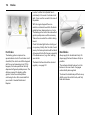
To hold bonnet in the open position, insert
the support rod, located on the underside
of the bonnet, into the slot provided.
Before closing bonnet, press the support
rod firmly into its retainers. Lower bonnet
gradually to be finally dropped by its own
weight.
Check that the bonnet is locked in position
by pulling at its front edge. If it is not locked
in position, repeat closing procedure.
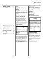
Seats, interior
Seats, interior
47
Seat adjustment
see page 2
Seat position
Adjust driver’s seat such that with the
driver sitting upright the steering wheel is
held in the area of its upper spokes with the
driver’s arms slightly bent.
The seat backrests must not be tilted too
far back (recommended tilting angle
approx. 25°).
9 Warning
Seat position .......................................
Head restraints ...................................
Rear seats 3........................................
Load compartment net 3 ..................
Load compartment cover 3 ..............
Lashing eyes 3 ...................................
Load anchorage rails 3 .....................
Notes on loading the vehicle.............
Cigarette lighter ) 3..........................
Ashtray 3 ............................................
Drink holders .......................................
Over-cab storage area 3...................
47
48
48
51
51
52
52
53
54
55
55
55
Disregard can lead to injuries which could
be fatal. Vehicle passengers should be
informed accordingly.
Head restraint position
The centre of the head restraint should be
at eye level. Adjust to highest position if
this is not possible for extremely tall
people, and adjust to lowest position for
extremely small people.
9 Warning
Disregard can lead to injuries which could
be fatal. Vehicle passengers should be
informed accordingly.
Setting – see page 4.
48
Seats, interior
Head restraints
Rear seats 3
Adjustments - see page 4.
On some variants, the rear passenger
compartment offers storage in the seat
trims.
To remove the head restraints, pull lock tab
and pull the restraint upwards.
To enable long items to be stored under
the seats the centre seat trim cover 3 can
be unclipped.
The load capacity can be increased further
by folding or removing the rear seats 3.
When folding or removing the rear seat
ensure the arm rests 3 are folded away in
their most upright position. Also remove
the lower seat trim side pockets 3
disconnecting them from the locating clips.
Seats, interior
Rear seat access 3
To facilitate access to the rear seats, fold
the seat backrest forwards. If necessary
release the two-latch seat belt from its
buckles.
9 Warning
Ensure that the backrest returns to its
correct position and the seat belt buckles
engage securely - see page 58.
Folding seats 3
On some variants, the cargo area can be
increased by folding up the rear seats.
Remove the head restraints. Pull the side
handle to release the backrest and fold
forward onto the seatbase, if necessary
releasing the two-latch seat belts from their
buckles.
Release both locking bars at the rear base
of the seat by pulling rearwards.
Lift and fold the seat assembly, until the
seat frame rests in place.
9 Warning
When folding the seat use caution beware of moving parts. Ensure the seat
is secure when completely folded.
49
To return the folding seat to the upright
position, support the seat assembly and
release the bar by pulling the bar directly
towards you. Gradually lower the seat
assembly, allowing the rear support legs to
fold down. Lower the seat completely,
ensuring the rear support legs are located,
and latched. Raise the backrest, reinstall
head restraints and connect the seat belts.
9 Warning
When installing the seat, ensure that the
seat is properly located on the anchor
points and that the locking catches are
fully engaged, the backrest is returned to
the correct position and the seat belts are
engaged securely.
50
Seats, interior
Removable rear seats 3
On some variants, the cargo area can be
increased by removing the rear seats.
Release the seats by pressing down and
sliding forward the locking catch located
on the left and right hand seat mountings.
With both catches raised, push the seat
unit towards the rear and release them
from the floor anchor points. The seat can
then be lifted out.
The seats must be removed through the
sliding door only.
9 Warning
Removable seats are heavy! Do not
attempt to remove without assistance.
When installing the seats, ensure that the
seats are properly located on the anchor
points and that the locking catches are
fully engaged.
9 Warning
When re-installing seats always ensure
that the row with the folding access
seat B is positioned correctly in front of
the fixed seat row A.
If the seats are incorrectly positioned,
access for passengers is seriously
impeded. Disregard of these instructions
may endanger life.
Seats, interior
51
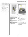
Installing (front or rear position)
Lift the covers to access the mountings,
insert the load compartment net rod into
the mounts and secure. Attach the straps
to the lashing eyes behind the front seats;
or to the rings on the rear seat frame, then
tension the straps.
Removing
Tilt strap length adjuster upwards and
unhook strap.
9 Warning
Load compartment net 3
The load compartment net can be fitted
behind the front or rear seats to separate
compartments when transporting luggage
or animals.
Loose objects in the luggage
compartment should be secured safely.
Load compartment cover 3
To remove:
Lift cover and disconnect from the side
guides.
Notes on loading
See page 53.
9 Warning
Do not place any heavy or sharp objects
on the cover.
Loose objects in the load compartment
should be secured safely.
52
Seats, interior
z cargo can then be secured in position
using lashing straps 3 attached to the
anchorage point
The maximum load of each anchorage
point is 75 kg. To prevent the possibility of
exceeding this maximum, the use of
ratchet type lashing straps is to be
avoided.
9 Warning
Loose objects in the luggage
compartment should be secured safely.
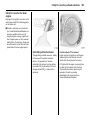
Lashing eyes 3
Load anchorage rails 3
Lashing eyes are mounted in the load
compartment to enable cargo to be
secured in position using lashing straps 3
or a luggage net 3.
Load anchorage rails 3 mounted in the
load compartment, provide adjustable
anchorage points for securing cargo.
z release centre pin of the anchorage
point, by pulling out against spring
tension
The maximum force applied to the lashing
eyes should not exceed 5000 N at 30°.
z slide the anchorage point to the required
location
z position the anchorage point directly
over the nearest suitable "locking hole"
z release the centre pin of the anchorage
point, ensuring the pin is located
correctly and the anchorage point is
securely locked
Seats, interior
Notes on loading the vehicle
z Heavy objects in the load compartment
should be placed as far forward as
possible. If objects are to be stacked, the
heavier objects should be placed at the
bottom. Unsecured objects in the load
compartment would be thrown forward
with great force in the event of heavy
braking, for example.
z Secure heavy objects with lashing straps
3 attached to the lashing points. If
heavy loads slip when the vehicle is
braked heavily or driven around a bend,
the handling of the vehicle may change.
53
z The warning triangle 3 and first aid kit 3
should always be freely accessible.
z Weights, payload and roof load - see
page 164.
z No objects should be placed on the
instrument panel. They are reflected in
the glass, obstruct the driver’s view and
will be thrown through the vehicle in the
event of heavy braking, for example.
z Driving with a roof load (see also page
95) increases the sensitivity of the vehicle
to cross-winds and has a detrimental
effect on vehicle handling owing to the
higher centre of gravity of the vehicle.
z No objects should be stored in any of the
airbag 3 inflation zones, as injuries may
be caused when the airbag is triggered.
9 Warning
z Bulky objects should not be transported
with the back doors open or ajar,
otherwise poisonous exhaust fumes may
enter the vehicle. In addition, the number
plate is only distinguishable and lit
correctly if the doors are closed.
Disregard of these instructions may lead
to injuries or endanger life. Vehicle
passengers should be informed
accordingly.
54
Seats, interior
The maximum power requirement of
electrical accessories must not exceed 120
watts.
Do not connect any current-delivering
accessories, e.g. electrical charging
devices or batteries.
Connected electrical accessories must
comply with the EC standard in terms of
electromagnetic compatibility
requirements laid down in DIN VDE 40 839,
otherwise vehicle malfunctions may occur.
The use of non-authorised accessories may
cause damage to the socket.
Cigarette lighter ) 3
With ignition switched on, press the
cigarette lighter. Heating up ceases once
element is glowing. Withdraw lighter.
Accessory socket
The socket for the cigarette lighter can be
used to connect electrical accessories when
the ignition is switched on.
An additional accessory socket 3 is located
in the rear of the vehicle.
When the engine is not running using these
accessory sockets will cause the battery to
be discharged.
Seats, interior
55
Ashtray 3
Drink holders
Over-cab storage area 3
Removable to enable universal use for
driver or passengers.
To use drink holders remove the ashtray
unit.
The total weight in this compartment must
not exceed 30 kg.
To be used only for ash and not for
combustible rubbish.
9 Warning
Disregard of these instructions may lead
to injuries or endanger life. Vehicle
passengers should be informed
accordingly.
To open: lift up the cover.
To empty: remove the ashtray from the
drink holder recess and empty.
56
Safety systems
Safety systems
Three-stage restraint system
The system comprises
z three-point seat belts
z belt tensioners on the front seats
z airbag systems for driver and front
passenger 3.
The three stages are activated in sequence
depending on the seriousness of the
accident:
Three-stage restraint system.............
Seat belts.............................................
Belt tensioners 3.................................
Airbag systems 3 ...............................
Child restraint systems 3 ...................
Exterior mirrors....................................
Aspherical exterior mirror ..................
Sun visors.............................................
Head restraints ...................................
Safety accessories 3 ..........................
56
57
59
61
68
74
74
74
74
74
z The automatic seat belt locking devices
prevent the belt strap from being pulled
out and thus ensure that the vehicle
occupants are retained in their seats.
z The front seat belt buckles are pulled
downwards. As a result, the seat belts
are instantaneously tightened and the
occupants are made aware of the
deceleration of the vehicle at a very early
stage. This reduces stress placed on the
body.
z The airbag system is additionally
triggered in the event of a serious
accident involving a frontal impact and
forms a safety cushion for the driver and
front passenger 3. The side airbag
system 3 protects the occupants in the
front of the vehicle in the event of side-on
collisions.
9 Warning
The airbag system serves to supplement
the three-point seat belts and belt
tensioners. The seat belts must therefore
always be worn. Disregard of these notes
can lead to injuries which may be fatal.
Vehicle passengers should be informed
accordingly.
Be sure to read the detailed descriptions
of all the restraint systems on the
following pages!
Safety systems
57
Seat belts
9 Warning
Always wear your seat belt - and that
means also in urban traffic and when you
are a rear seat passenger. It can save
your life!
Pregnant women too must always wear a
seat belt.
In the event of an accident, persons not
wearing seat belts endanger their fellow
occupants and themselves.
Seat belts are designed to be used by only
one person at a time. They are only
suitable for children aged up to 12 or
smaller than 150 cm if used in conjunction
with a child seat.
Three-point seat belts
The vehicle is equipped with three-point
seat belts with automatic retractors and
locking devices, allowing freedom of body
movement although the spring tensioned
belts are always a snug fit.
The belt has a “vehicle sensitive retractor”
which is designed to lock during heavy
acceleration or deceleration in any
direction.
Using the belts
Fitting the belt
Pull the belt out evenly from the retractor
and guide it across the body, making
certain that it is not twisted.
Insert the latch plate into the buckle. The
seat backrest must not be tilted back too
far; the recommended angle of inclination
is approx. 25°. The lap belt must not be
twisted and must fit snugly across the
body. Tension the belt frequently whilst
driving by tugging the diagonal part of the
belt.
9 Warning
On pregnant women in particular the lap
belt must be positioned as low as
possible across the pelvis in order to
prevent pressure on the abdomen.
Bulky clothing prevents the belt from fitting
properly. The belt must not rest against
hard or fragile objects in the pockets of
your clothing (e.g. ballpoint pens, keys,
spectacles) because these could cause
injury. Do not place any objects (e.g.
handbags) between the belt and your
body.
58
Safety systems
Upper anchorage point
height adjustment 3
z Do not adjust height whilst driving
z Slide adjuster up or down to desired
position
Adjust height such that the belt passes
over the wearer’s shoulder and rests
against the shoulder. It must not pass over
the neck or upper arm.
Removing the belt
To remove the belt, depress the red pushbutton on the buckle; the belt will retract
automatically.
Two-latch belt 3
Before fitting the belt, first insert lower
latch plate into the buckle on the outside of
the seat.
The belt can now be used in the same way
as a standard seat belt.
9 Warning
The seat belt will not be effective in the
event of an accident if the lower latch is
not correctly fitted.
When releasing the seat belt, ensure that
the central buckle is always released
before the buckle on the side of the seat.
Always remove the lower latch plate from
the outside buckle before removing seats
from the vehicle or to facilitate access to
the rear seats 3 - see page 48.
Safety systems
Inspection of belts
Periodically inspect all parts of the belt
system for damage and to make sure they
are functioning properly. Have damaged
parts replaced. After an accident,
overstretched belts must be replaced by
new ones. We recommend consulting your
Vauxhall Authorised Repairer.
59
Actuation of belt tensioners
The belt tensioners must be replaced after
activation. We recommend that you
consult your Vauxhall Authorised Repairer.
9 Warning
The belt tensioners are operational only
when the control indicator is unlit.
Do not perform any alterations on the
belts, their anchorages, the automatic
retractors or the belt buckles.
The seat belts remain fully operational
even when the belt tensioners have been
actuated.
Make sure that belts are not damaged or
trapped by sharp-edged objects.
Belt tensioners 3
The seat belt systems incorporate belt
tensioners. In the event of a head-on or
tail-end collision the belt buckles are pulled
downwards; the diagonal and lap belts are
instantaneously tightened.
60
Safety systems
The system’s integrated self-diagnostics
allows faults to be quickly remedied. Have
Car Pass on hand when consulting a
Vauxhall Authorised Repairer.
Important
z Accessories not released for your vehicle
type and other objects must not be fixed
or placed within the action zone of the
belt tensioners as they may result in
injury if the belt tensioners are triggered.
z Do not make any modifications to the
components of the belt tensioners, as
this will render the vehicle unroadworthy.
Belt tensioner control indicator
The seat belt tensioners are monitored
electronically together with the airbag, and
their operational readiness shown by the
control indicator in the instrument panel.
When the ignition is switched on, the
control indicator lights up, then
extinguishes. If it does not light up or if it
lights up during driving, there is a fault in
the airbag system or the belt tensioners
(see also page 64).
9 Warning
Have the cause of the fault remedied. We
recommend that you consult your
Vauxhall Authorised Repairer.
9 Warning
Improper handling (e.g. removal or
installation) can activate the belt
tensioners – risk of injury.
z The belt tensioner and airbag system
control electronics can be found in the
centre console area. In order to avoid
malfunctions, do not store magnetic
objects in this area.
z We recommend that you have the front
seats removed by a Vauxhall Authorised
Repairer.
z The belt tensioners only actuate once.
Please replace belt tensioners that have
been triggered. We recommend that you
consult your Vauxhall Authorised
Repairer.
z When disposing of the vehicle, please
observe the applicable safety
regulations. Please have the vehicle
disposed of by a disposal company. We
recommend that you consult your
Vauxhall Authorised Repairer.
Safety systems
61
When triggered, the driver’s airbag and
front passenger airbag 3 inflate in
milliseconds and form safety cushions for
the driver and front passenger. The
forward movement of the driver and front
passenger is checked and the risk of
injuries to the upper body and head
thereby substantially reduced.
z No impairment of view will occur,
because the airbags inflate and deflate
so quickly.
9 Warning
Airbag systems 3
Front airbag
The front airbag system is identified by the
word “Airbag” on the steering wheel and
above the glove compartment 3.
The front airbag system comprises:
z an airbag with an inflator in the steering
wheel, and a second one above the
glove compartment 3
z the control electronics with impact
sensor
z the airbag system control indicator v in
the instrument panel.
z Front passenger airbag deactivation 3
The front airbag system is triggered:
z depending on the severity of the
accident
z depending on the type of impact
z within the range shown in the illustration
z independently of the side airbag and
curtain airbag systems 3.
Examples:
z Impact against a non-yielding obstacle:
the front airbag is triggered at low
vehicle speed.
z Impact against a yielding obstacle (such
as another vehicle): the front airbag is
only triggered at a higher vehicle speed.
The front airbag system provides
optimum protection when the seat,
backrest and head restraint are correctly
adjusted. Adjust the driver's seat
according to the occupant's height such
that with the driver sitting upright, the
steering wheel is held in the area of its
upper spokes with the driver's arms
slightly bent. The passenger seat should
be as far back as possible, with the
backrest upright. Do not place the head,
body, hands or feet on the cover of the
airbag system.
Do not place any objects in the area in
which the airbags inflate.
The three-point seat belt must be
correctly fitted (see page 57).
6
62
Safety systems
The front airbag system will not be
triggered in the event of
z the ignition being switched off
z minor frontal collisions
z accidents in which the vehicle overturns
z collisions involving a side or rear impact
where it would not be of benefit to the
occupants.
9 Warning
Seat belts must therefore always be worn.
The front airbag system serves to
supplement the three-point seat belts. If
you do not wear your seat belt you risk
being seriously injured, or even thrown
from the vehicle, in the event of an
accident.
The belt helps to keep you in the correct
seating position, in which the front airbag
system will provide you with effective
protection in the event of an accident.
Side airbag 3
The side airbags are mounted on the
outboard sides of the front seat backrests
to protect the occupants in the event of a
severe side impact.
The side airbag system comprises:
z an airbag with inflator in the back of the
driver's and front passenger's seat
respectively
z the control electronics
z side impact sensors
z the airbag systems control indicator v in
the instrument panel.
The side airbag system will be triggered:
z depending on the severity of the
accident
z depending on the type of impact
z within the range shown in the illustration
z independently of the front airbag
system.
Safety systems
63
When triggered the side airbag inflates in
milliseconds and forms a safety cushion for
driver and/or front passenger in the
respective door area. The risk of injury to
the upper body in the event of a side
impact is thereby substantially reduced.
9 Warning
There must be no objects in the area in
which the airbag inflates or in the area
between the seat backs and the vehicle
body. Do not place the hands or arms on
the covers of the airbag systems.
Important information - see page 66.
The three-point seat belt must be
correctly fitted - see page 57.
The side airbags will not be triggered in the
event of:
z the ignition being switched off,
z frontal collisions,
z accidents in which the vehicle overturns,
z collisions involving a rear impact,
z collisions involving a side impact outside
the passenger cell.
Curtain airbag 3
The curtain airbag system is identified by
the badge AIRBAG on the head lining trim.
The curtain airbag system will be triggered:
z depending on the severity of the
accident,
The curtain airbag system comprises:
z depending on the type of impact,
z an airbag with inflator in the roof frame
on the driver’s and passenger’s side
respectively,
z within the range shown in the illustration,
z the control electronics,
z the side impact sensors,
z the airbag systems control indicator v in
the instrument panel.
z together with the side airbag system,
z independently of the front airbag
system.
6
64
Safety systems
When triggered the curtain airbag inflates
within milliseconds and provides a safety
barrier in the head area on the respective
side of the vehicle. This reduces the risk of
injury to the head considerably in case of a
side impact.
9 Warning
Have the cause of the fault remedied. We
recommend that you consult your
Vauxhall Authorised Repairer.
9 Warning
The system's integral self-diagnosis facility
allows faults to be quickly remedied. Have
your Car Pass ready to hand when
consulting a Vauxhall Authorised Repairer.
There must be no objects in the area in
which the airbag inflates. Do not place
the hands or arms on the covers of the
airbag systems. Important information –
see page 66.
The three-point seat belt must always be
correctly fitted – see page 57.
z collisions involving a rear impact,
Airbag control indicator v
The front airbag system, side airbag
system 3 and curtain airbag system 3 are
monitored electronically together with the
belt tensioners, and their operational
readiness shown by the control indicator in
the instrument panel. When the ignition is
switched on, the control indicator lights up
then extinguishes. If it does not light up, or
if it lights up during driving, there is a fault
in the airbag systems or the belt tensioners.
z collisions involving a side impact outside
the passenger cell.
The systems might not be triggered in the
event of an accident.
The curtain airbags will not be triggered in
the event of:
z the ignition is switched off,
z frontal collisions,
z accidents in which the vehicle overturns,
Safety systems
Front passenger airbag deactivation 3
Front and side airbag systems must be
deactivated if a child restraint system is to
be mounted on the front passenger seat.
The belt tensioners as well as all airbag
systems for the driver’s seat remain active
when the front passenger seat’s systems
are disengaged.
The switch for deactivating or activating
the airbag system is located on the front
passenger door.
The chosen setting remains active after the
ignition has been switched off. The control
indicator H for front passenger airbag
deactivation is located in the instrument
panel.
To deactivate
With the front passenger door open, press
switch in and rotate anti-clockwise to
"OFF" position.
The airbag systems for the front passenger
seat are now deactivated.
65
With the ignition switched on the control
indicator H will remain illuminated to
indicate deactivation. It is now safe to
place a child seat on the front passenger
seat.
6
66
Safety systems
To activate:
With the front passenger door open press
switch in and rotate clockwise "ON"
position. Front passenger airbag is now
activated. Upon switching the ignition on
the control indicator H will illuminate
briefly and then extinguish indicating the
passenger airbag is active.
If H remains illuminated in conjunction with
v indicates a fault within the system.
9 Warning
Have the cause of the fault remedied. We
recommend that you consult your
Vauxhall Authorised Repairer.
Important
z Accessories not released for your vehicle
type and other objects must not be
affixed or placed in the area in which the
airbags inflate, as they could cause
injury when the airbags are triggered.
z Do not place any objects between the
airbag systems and the vehicle
occupants; danger of injury.
z Do not stick or place anything on the
steering wheel, instrument panel, front
seat backrests in the vicinity of the
airbags and seat areas or cover them
with other materials.
z The airbag systems and belt tensioner
control electronics can be found in the
centre console area. In order to avoid
malfunctions, do not store magnetic
objects in this area.
z Use only a dry cloth or interior cleaner to
clean the steering wheel, instrument
panel, front seat backrests, roof frame
and seat area of the front passenger
seat. Do not use any aggressive cleaning
agents.
z Only protective covers which are
approved for your Vivaro with side
airbag 3 may be fitted on the front
seats. When fitting the protective covers,
make sure that the airbag units on the
outboard sides of the front seat
backrests are not covered.
z The airbag systems are triggered
independently of each other depending
on the severity of the accident and the
type of impact. The side airbag system 3
and the curtain airbag system 3 are
triggered together.
z Each airbag can be triggered only once.
Once triggered, an airbag must be
replaced without delay. We recommend
that you consult your Vauxhall
Authorised Repairer.
z The speeds, directions of movement and
deformation properties of the vehicles,
and the properties of the obstacle
concerned, determine the severity of the
accident and triggering of the airbags.
The degree of damage to your vehicle
and the resulting repair costs alone are
not indicative that the criteria for
triggering of the side airbag were met.
Safety systems
z Do not perform any modifications to the
components of the airbag systems, as
this will render the vehicle unroadworthy.
9 Warning
While using a child restraint system on
the front passenger seat, the airbag
systems for the front passenger seat must
be deactivated; if not, the triggering of
the front or side airbag poses the risk of
fatal injury to the child.
9 Warning
The systems can be triggered abruptly
and cause injury if they are handled
improperly.
z We recommend having the steering
wheel, the instrument panel, all panelling
parts, the door seals, the handles and
the front seats removed by your
Vauxhall Authorised Repairer.
z When disposing of the vehicle, please
observe the applicable safety
regulations. Please have the vehicle
disposed of by a disposal company. We
recommend that you consult your
Vauxhall Authorised Repairer.
9 Warning
Child restraint systems as well as other
heavy objects must never be carried on
the lap of passengers; risk of fatal injury.
67
This is especially the case if backwardsfacing child restraint systems are used on
the front passenger seat.
The system for deactivating the front
passenger seat’s airbag systems is
indicated a sticker on the side of the
instrument panel, visible when passenger
door is open.
68
Safety systems
Child restraint systems 3
Vauxhall child restraint systems are
designed specifically for your vehicle and
thus provide optimum safety for your child
in the event of impact. The use of a
Vauxhall Child restraint system is therefore
recommended.
9 Warning
While using a child restraint system on
the front passenger seat, the airbag
systems for the front passenger seat must
be deactivated; if not, the triggering of
the front or side airbag poses the risk of
fatal injury to the child.
This is especially the case if backwardsfacing child restraint systems are used on
the front passenger seat.
Selecting the right system
Your child should be transported facing
rearwards in the vehicle as long as
possible. It is appropriate to change the
system when the child’s head can no longer
be properly supported at eye height. The
child’s cervical vertebrae are still very weak
and in an accident they suffer less stress in
the semi-prone rearward position than
when sitting upright.
Note
z Children under 12 years or under 150 cm
tall should only travel in an appropriate
child safety seat.
z When transporting children, use the child
restraint systems suitable for the child's
weight.
z Ensure that the child restraint system to
be installed is compatible with the
vehicle type.
z The covers of the Vauxhall child restraint
system can be wiped clean.
z Do not stick anything on the child
restraint systems and do not cover them
with any other materials.
z A child restraint system which has been
subjected to stress in an accident must
be replaced.
z Ensure that the mounting location of the
child restraint system within the vehicle is
correct.
z You should also observe the instructions
on installation and use supplied with the
child restraint system.
Safety systems
The following Vauxhall child restraint
systems have been approved for
installation in your Vivaro:
Group, weight and age
class1)
0
From birth - 10 kg,
0 - 10 months
0+
I
II
III
1)
From birth - 13 kg,
0 - 2 years
From 9 - 18 kg,
8 months - 4 years
from 15 - 25 kg,
3 years - 7 years
Vauxhall
system
Baby Safe
Duo Isofix
Kid
from 22 - 36 kg,
6 years - 12 years
We recommend the use of each system
until the child reaches the upper weight
limit.
If child restraint systems of other
manufacture are to be installed, ensure
that they conform to the appropriate
safety regulations.
9 Warning
Disregard of these instructions may lead
to injuries or endanger life.
69
The country in which you are travelling
may prohibit child seat installation in
certain locations. Always observe local or
national regulations.
6
70
Safety systems
Front seats - all variants
Group, weight and age class
Facing
direction
Single seat - front passenger 1)
without
airbag
with airbag
- no side
airbag
with side
airbag
Bench seat - front passenger
without airbag
with airbag
centre
outer
centre
outer
0:
0+:
up to 10 kg or approx. 10 months
up to 13 kg or approx. 2 years
Rearward
U
U2)
U2
X
U
X
U2
I:
9 to 18 kg or approx. 8 months - 4 years
Forward
U
U2
U2
UF
U
UF
U2
II:
III:
15 to 25 kg or approx. 3 - 7 years
22 to 36 kg or approx. 6 - 12 years
Forward
U
U2
U2
UF
U
UF
U2
1)
2)
If adjustable, ensure seat is in its rearmost position. Make sure vehicle seat belt is as straight as possible between shoulder and upper achorage point.
Ensure the front passenger airbag system is deactivated when installing a child seat in this position. See page 65.
U =
UF =
X =
Suitable for universal category restraint systems for use in this mass group, in conjunction with three-point seat belt.
Suitable for universal category forward facing restraint systems for use in this mass group, in conjunction with three-point seat belt.
Seat position not suitable for children of this mass group.
9 Warning
While using a child restraint system on the front passenger seat, the airbag systems for the front passenger seat must be deactivated; if
not, the triggering of the front or side airbag poses the risk of fatal injury to the child.
This is especially the case if backwards-facing child restraint systems are used on the front passenger seat.
Safety systems
71
Combi - rear seats
Group, weight and age class
Facing
direction
3rd row bench seat
Outer
Centre
Outer
Centre
U
U,+
X
X
0:
0+:
up to 10 kg or approx. 10 months
up to 13 kg or approx. 2 years
I:
9 to 18 kg or approx. 8 months - 4 years Forward
U
U,+
X
X
II:
III:
15 to 25 kg or approx. 3 - 7 years
22 to 36 kg or approx. 6 - 12 years
U
U
X
X
U =
L =
Suitable for universal category restraint systems for use in this mass group, in conjunction with three-point seat belt.
Suitable only for specifically approved child restraints. Vauxhall has approved child restraint systems from the ’Baby-safe’, ’Duo-Isofix’ and ’Kid’
ranges. We recommend that you consult a Vauxhall Authorised Repairer.
Seat with Isofix mounting available. When mounting Isofix, only Isofix child restraint systems that have been approved for the vehicle may be used.
We recommend that you consult a Vauxhall Authorised Repairer.
Seat position not suitable for children of this mass group.
+
=
X =
Rearward
2nd row bench seat
Forward
72
Safety systems
Tour - rear seats
Group, weight and age class
Facing
direction
2nd row bench seat
Outer
3rd row bench seat
Centre
Outer
Centre
1)
X
0:
0+:
up to 10 kg or approx. 10 months
up to 13 kg or approx. 2 years
Rearward
U
U,+
X
I:
9 to 18 kg or approx. 8 months - 4 years
Forward
U
U,+
X1
X
II:
III:
15 to 25 kg or approx. 3 - 7 years
22 to 36 kg or approx. 6 - 12 years
Forward
U
U
X1
X
1)
On left-hand drive 7 seater models (2 seat bench in 2nd row) it is permissible to install a universal child seat on the third seat row but only on the right
hand outboard side due to increased clearance in front of it.
U =
L =
+
=
X =
Suitable for universal category restraint systems for use in this mass group, in conjunction with three-point seat belt.
Suitable only for specifically approved child restraints. Vauxhall has approved child restraint systems from the ’Baby-safe’, ’Duo-Isofix’ and ’Kid’
ranges. We recommend that you consult a Vauxhall Authorised Repairer.
Seat with Isofix mounting available. When mounting Isofix, only Isofix child restraint systems that have been approved for the vehicle may be used.
We recommend that you consult a Vauxhall Authorised Repairer.
Seat position not suitable for children of this mass group.
Safety systems
Crew Cab - rear seats
Group, weight and age class
Facing
direction
Rearward
Rear bench seat
Outer
Centre
X
X
0:
0+:
up to 10 kg or approx. 10 months
up to 13 kg or approx. 2 years
I:
9 to 18 kg or approx. 8 months - 4 years Forward
X
X
II:
III:
15 to 25 kg or approx. 3 - 7 years
22 to 36 kg or approx. 6 - 12 years
X
X
X =
Seat position not suitable for children of this mass group.
Forward
73
74
Safety systems
Sun visors
Safety accessories 3
The sun visors are padded and can be
swung up and down and to the side for
protection of driver and passenger against
glare.
The wide range of Vauxhall accessories
allows you to equip your vehicle in
accordance with your own wishes. In
addition to safety accessories, items for
improving comfort and a complete range
of vehicle care products you will find many
articles which will be of great value to you
when needed.
Head restraints
Exterior mirrors
For the safety of pedestrians, the exterior
mirrors will swing out of their normal
mounting position in the event of an
accident-like impact.
Aspherical exterior mirror
Increases the field of vision. Slight
distortion means that it is somewhat
difficult to estimate the distance between
the vehicle and those behind it.
Do not attach objects or components that
are not approved for the Vivaro, to the
head restraints. These affect the protective
effect of the head restraints and can be
propelled through the vehicle in an
uncontrolled manner if the driver brakes
hard or an accident occurs.
All items are “Genuine Vauxhall Parts and
Accessories”, guaranteeing high quality
and an accurate fit.
Your Vauxhall Authorised Repairer will be
happy to advise you, for example with
regard to:
z
z
z
z
z
z
z
z
z
z
z
z
Vauxhall child restraint system
Tow rope
Tow rod
Jump leads
Spare bulb kit
Spare fuse kit
Halogen fog lights
Mud flaps
Magnetic light
Warning triangle
First-aid kit (box)
First-aid kit (cushion)
Lighting
Lighting
75
Vehicles with daytime running lights 3:
When the ignition is on, the dipped beam is
on and the instrument illumination is
subdued.
The daytime running lights go off when the
ignition is switched off.
Follow the regulations of the country in
which you are driving when using daytime
running lights and front fog lights 3.
Driving abroad - see page 78.
Exterior lights ......................................
Automatic dipped beam
activation 3 ......................................
Headlight range adjustment ? .........
Fog tail light r ...................................
Front fog lights > 3...........................
Reverse lights ......................................
Door-to-door illumination 3 ..............
Interior light.........................................
Instruments, cigarette lighter ............
Headlights when driving abroad ......
75
76
Exterior lights
76
77
77
77
77
77
78
78
7
0
9P
Turn light switch:
=
=
=
Off
Parking lights
Dipped or main beam
Dipped/main beam and headlight flash,
see page 12.
In positions 0 and 9, the tail lights and
number plate light are also illuminated.
76
Lighting
To deactivate:
1. Switch on the ignition.
2. Turn light switch to 0 and return 7.
3. Repeat stage 2 within approximately 5
seconds.
This action is confirmed with a single
audible warning.
For reasons of safety it is advisable to have
the automatic dipped beam function
activated.
Automatic dipped beam
activation 3
Dipped beam switches on or off
automatically when the engine is running
based on the outside light conditions.
The exterior lights switch off when the
ignition is switched off.
To activate:
1. Switch on the ignition.
2. Turn light switch to 0 and return 7.
3. Repeat stage 2 within approximately 5
seconds.
This action is confirmed with a double
audible warning.
Turn signals, hazard warning
flashers
See page 13.
Headlight range adjustment ?
With dipped beam switched on, adjust
headlight range to suit vehicle load.
Correct adjustment of the headlight range
reduces dazzle for other road users.
z No load
=
0
z Loaded up to permissible
maximum weight
=
4
Lighting
Fog tail light r
Front fog lights > 3
Rotate switch, control indicators > and r
in instrument panel:
7
>
> and r
=
=
=
Off
Front fog lights on
Fog tail light and
front fog lights on
Reverse lights
Come on when reverse gear is engaged
and ignition is switched on.
77
Door-to-door illumination 3
Interior light
The headlights are switched on and remain
illuminated for a short time after the
vehicle is parked.
Operated by tilting the light lens. With the
light in its central position, the light
functions as a courtesy light and
illuminates when the front doors are
opened.
To activate:
1. Switch off ignition.
2. Remove ignition key.
3. Open driver’s door.
4. Pull lever towards steering wheel.
The dipped beam illuminates for approx.
30 seconds. This action can be repeated up
to four times to a maximum period of two
minutes.
Switching on the ignition or rotating the
light switch cancels the function before the
lights automatically switch off.
Once the front doors are closed, the
courtesy light goes out after a 15 second
delay.
The interior light extinguishes immediately
if the ignition is switched on.
78
Lighting
Instruments, cigarette lighter
Comes on when exterior lights are switched
on.
Headlights when driving abroad
The asymmetrical dipped beam increases
the field of vision on the near side of the
lane.
When driving in countries which drive on
the opposite side of the road, this causes
glare for oncoming traffic.
Load compartment lights
Van
Operated by tilting the light lens.
Combi / Tour / Crew Cab
Operated by tilting the light lens to one of
3-positions:
z On constantly
z Controlled by the function of the interior
light
z Off constantly
To avoid glare, conventional headlight
glasses must be provided with a black
cover strip. Consult a workshop. We
recommend your Vauxhall Authorised
Repairer.
Windows
Windows
79
9 Warning
Care must be taken when operating the
electrically operated windows. There is a
risk of injury, particularly for children, and
a danger that articles could become
trapped.
Vehicle passengers should be informed
accordingly.
Make sure that all vehicle occupants
know how to operate the windows
correctly.
Door windows ..................................... 79
Electrically operated door windows 3 80
Sliding side windows 3....................... 80
Keep a close watch on the windows when
closing them. Ensure that nothing
becomes trapped in them.
Before leaving the vehicle, remove the
ignition key in order to prevent
unauthorized operation.
Door windows
The door windows can be operated with
the crank.
80
Windows
Electrically operated door
windows 3
The passenger’s window is operated by a
switch in each front door.
Sliding side windows 3
The driver’s window is operated by the
switch located in the driver’s door.
To open the window, push the top of the
switch and to close, pull the top of the
switch. The window stops when the switch
is released.
To close, pull up catch and slide window
until catch engages.
To open the window, push the top of the
switch and to close, pull the top of the
switch. The window stops when switch is
released.
With the engine running: briefly pushing or
pulling the switch fully opens or closes the
driver’s side window. Briefly press the
switch again to stop the window during this
operation.
9 Warning
Before leaving the vehicle, remove the
ignition key in order to prevent
unauthorized operation of the windows
(risk of injury).
To open, pull up catch and slide open.
Note: during window opening or closing,
keep the catch raised to allow the glass
sufficient clearance.
Heating, ventilation
Heating, ventilation
Heating and ventilation system ........
Rear air vents 3 ..................................
Heating the foot area ........................
Window demisting and defrosting....
Re-circulation button..........................
Air conditioning system 3..................
Rear air conditioning system 3 .........
Heated rear windows 3, heated
exterior mirrors 3 .............................
Heated front seats 3..........................
81
Heating and ventilation system
Vauxhall air mixture system: by mixing cold
and hot air the temperature can be
regulated without delay and held
practically constant at all speeds.
81
83
84
84
85
85
86
Heating and ventilation controls
87
88
The rotary switch can be set to any
intermediate position in order to adjust the
air distribution to suit personal
requirements.
Air distribution switch
M To head area
L To head and foot area
K
To foot area
J To defrosters and foot area
V To defrosters
Open the ventilation jets when the switch is
set to M or L.
82
Heating, ventilation
Temperature switch
To red
Hotter
Fan switch
Four speeds:
To blue
0
Off
4
High speed
Colder
The rate of air flow is determined by the
fan. The fan should therefore also be
switched on during driving.
Centre ventilation jets
Pleasant ventilation to the head area is
controlled by the position of the
temperature switch.
To open jets, turn regulating wheel:
Turn to left
=
Turn to right =
Open
Closed
The air supply is increased by switching on
the fan.
The air flow can be directed as desired by
tilting and swivelling the fins.
Heating, ventilation
83
Side ventilation jets
Rear air vents 3
Ventilation
Depending upon the position of the
temperature switch, air will be directed into
the vehicle via these jets.
Operational when air distribution switch is
set to L, K or J.
z Turn temperature switch to blue.
Unheated or heated air will be directed into
the rear passenger compartment.
z For maximum ventilation in head area:
set air distribution switch to M and open
all jets.
The jets are opened and closed by means
of the regulating wheel.
The air flow can be directed as desired by
tilting and swivelling fins.
To increase the air supply, switch on the
fan.
Door window defroster vents
Air distribution switch set to V or J: cold
or heated air will be directed onto the
windscreen and onto the door windows
(mainly in the area of the exterior mirrors).
The air flow is biased towards the central
and right hand vents for optimum
distribution.
z Switch on fan.
z For ventilation to foot area: set air
distribution switch to K.
z For simultaneous ventilation to head
and foot areas: set air distribution switch
to L.
84
Heating, ventilation
Heating
The amount of heat is dependant on the
engine temperature and is thus not fully
attained until the engine is warm.
For rapid warming of the passenger
compartment,
z Turn temperature switch to red.
z Switch on fan.
z Set the air distribution switch to the
desired position.
The comfort and general well-being of the
vehicle occupants are to a large extent
dependent on a correct setting of the
ventilation and heating.
Heating the foot area
Window demisting and defrosting
z Turn temperature switch to red.
z Turn temperature switch to red.
z Set the air distribution switch to K.
z Switch on fan.
z Switch on fan.
z Set air distribution switch to V.
z Open side ventilation jets as required
and direct them towards the door
windows.
z Close centre ventilation jets.
z Switch on heated rear windows.
For simultaneous warming of the foot area,
set air distribution switch to J.
Heating, ventilation
85
Once activated the air conditioning system
is operated via the normal heating and
ventilation controls.
To improve efficiency of the air
conditioning, always close the windows to
prevent chilled air from escaping.
Switching on the air conditioning will assist
in windscreen demisting.
In very hot temperatures, before switching
on the air conditioning, allow hot air to
escape from the vehicle by opening the
windows.
Re-circulation button
Air conditioning system 3
During ’normal’ operation, the heating and
ventilation and air conditioning systems
use outside air, however, to prevent fumes
from entering the vehicle when in
stationary traffic press the 4 button,
contol indicator illuminates and air will be
recirculated.
The air conditioning system is designed to
operate in conjunction with the heating
and ventilation system to provide
maximum comfort under any weather
conditions.
Recirculated air should only be used for
brief periods due to the gradual
deterioration in the air quality and increase
in humidity.
The air conditioning system cools the air
and removes moisture from it. It is
operational only in temperatures above
approx. +4 °C, with the engine running and
with the fan switched on:
Press AC button - control
indicator illuminates
Press AC button again
=
on
=
off
When the system is switched on, at least
one ventilation jet must be open so that the
evaporator does not ice up due to lack of
air movement.
When the air conditioning is on, fuel
consumption increases. Switch off the
system whenever it is not required.
Maintenance
To ensure efficient performance of the air
conditioning system, it must be switched on
once a month for a short time, irrespective
of the weather and time of year (possible
only when outside temperature is above
+4 °C).
Malfunctions in the system must not be
rectified by the owner; consult a workshop.
We recommend your Vauxhall Authorised
Repairer.
86
Heating, ventilation
Glove compartment cooler 3
Slide the control upwards to allow the air
conditioning system to also keep the
contents of the glove compartment cool.
Rear air conditioning system 3
The rear air conditioning 3 system cools
the air and removes moisture from it. It is
operational only in temperatures above
approx. +4 °C, with the engine running.
It is actuated in conjunction with the
driver’s compartment air conditioning:
Press AC button
Press AC button
again
=
=
on
off
Rear passenger compartment
fan switch 3
The fan assists air flow to the passenger
compartment. Switching on the fan whilst
the air conditioning is actuated, will allow
conditioned air to be distributed.
The rate of air flow is determined by the
fan.
3 speeds:
0
Off
3
High speed
When the system is switched on, at least
one ventilation jet, located in the roof must
be open so that the evaporator does not
ice up due to lack of air movement.
Heating, ventilation
Rear passenger compartment
heating 3
The rate of air flow is determined by the
fan.
Heated rear windows 3,
heated exterior mirrors 3
The fan assists air flow to the rear
passenger compartment via the rear air
vents.
3 speeds:
Operates only with engine running.
0
Off
Pushbutton Ü on instrument panel.
3
High speed
Press
Press again
=
=
87
on
off
Control indicator on pushbutton
illuminates when in use.
Turn off as soon as rear vision is clear. The
heating switches off automatically after
approx. 10 minutes.
88
Heating, ventilation
Heated front seats 3
Pushbutton ß in trim panels of the seat.
Operate only with engine running.
Press
=
on
Press again
=
off
Seat heating is thermostatically controlled
and will automatically cease when the seat
temperature is sufficient. The control
indicator will illuminate when system is on,
not just when heating.
Tecshift
Tecshift
89
The semi-automatic Tecshift transmission
permits manual (manual mode) or
automatic gearshifting (automatic mode),
both with fully automatic clutch control.
9 Warning
Disregard of these instructions may lead
to injuries or endanger life.
Transmission display ..........................
Starting the engine.............................
Tecshift operation ..............................
Winter programme V.........................
Laden programme kg ........................
Kickdown .............................................
Engine braking assistance .................
Stopping the vehicle...........................
Parking ................................................
Rocking the vehicle.............................
Manoeuvring the vehicle....................
Fault W................................................
Interruption of power supply .............
89
89
90
91
92
92
92
93
93
93
93
94
94
Transmission display
Shows the mode, programme and current
gear.
Starting the engine
Depress foot brake, turn on ignition.
If T is shown in the transmission display
the foot brake is not depressed. When "N"
is shown in the transmission display the
engine can be started.
It is not necessary to select the neutral "N"
position before starting. If a gear other
than "N" is selected, depress the foot brake
and there will be a short delay whilst the
transmission automatically shifts into
neutral.
90
Tecshift
Automatic mode
When the engine is started, Tecshift is in
automatic mode "A" is shown in the
transmission display.
To engage 1st gear depress foot brake and
move selector lever towards +.
The vehicle will begin to "creep" when the
foot brake is released without accelerating.
It is possible to start off quickly by releasing
the foot brake and accelerating.
Tecshift operation
The selector lever needs to be moved in the
appropriate direction only slightly. It then
returns to the centre position. Observe the
gear / mode indicator in the transmission
display.
Selecting neutral
Move the selector lever toward N.
In automatic mode the transmission shifts
to other gears automatically dependent on
driving conditions.
Manual mode
Manual gearshifting is possible in manual
mode. If the vehicle is in automatic mode,
manual mode can be selected by moving
the selector lever toward A/M. The current
gear will appear in the transmission
display.
To engage 1st gear depress foot brake and
move selector lever towards + or - and 1 will
appear in the transmission display.
Moving selector lever toward:
+
Shifts to a higher gear.
-
Shifts to a lower gear.
If the engine speed is too low Tecshift will
automatically shift to a lower gear even in
Manual mode. This prevents the engine
from stalling.
If a higher gear is selected when the
running speed is too low, or a lower gear
when the speed is too high, no shift is
effected. This prevents the engine from
running at too low or too high revs.
Gears can be skipped by moving the
selector lever repeatedly at short intervals.
Tecshift
91
In order to protect Tecshift at extremely
high clutch temperatures, an intermittent
audible warning may sound. In such cases
depress the foot brake, select "N" and
apply the handbrake allowing the clutch to
cool down.
If the vehicle is switched to manual mode
while winter programme is active, the
Winter programme is switched off.
Selecting reverse
Engage only when the vehicle is stationary.
With the foot brake depressed, move the
selector lever toward R. Reverse gear is
engaged and "R" appears in the
transmission display.
The vehicle begins to creep when the foot
brake is released. Accelerate gently to
move.
Winter programme V
In the event of difficulties starting-off on
slippery surfaces, press button V and V is
shown in the transmission display. Tecshift
switches to automatic mode and the
vehicle sets off in a suitable gear.
The Winter programme is switched off by:
z pressing button V again,
z turning off the ignition.
92
Tecshift
Engine braking assistance
Automatic mode
When driving downhill Tecshift does not
shift into the higher gears until a fairly high
engine speed has been reached. During
braking Tecshift shifts down to a lower
gear in good time.
Manual mode
To utilize the engine braking effect, select a
lower gear in good time when driving
downhill.
Laden programme kg
Kickdown
It is possible to use Laden programme in
both manual and automatic modes. In
both cases, the gear shifting patterns are
adapted automatically for carrying an
increased payload. Press button kg, Laden
programme will be selected and kg will
appear in the transmission display. Tecshift
will then select optimized gear shift
patterns.
Accelerator pedal pressed past the
pressure point: below certain speeds, the
transmission shifts down into a lower gear.
Full engine power is available for
acceleration.
The Laden programme is switched off by:
Without kickdown this automatic shift is
not affected in manual mode.
z pressing button kg again,
z turning off the ignition.
When the engine speed approaches its
upper limit, the transmission shifts to a
higher gear during kickdown even in
manual mode.
Tecshift
Stopping the vehicle
Parking
In automatic or manual mode, once the
vehicle is stationary first gear engages
automatically and the clutch opens. In R,
reverse remains engaged.
Before leaving the vehicle:
When stopping on gradients engage
handbrake or depress brake pedal. To
prevent overheating of the clutch, an
intermittent, audible warning may sound
as a signal to depress the foot brake or
apply the handbrake.
Switch off engine if stopping for a lengthy
period, e.g. in traffic jams.
93
z engage handbrake,
z remove ignition key.
The most recently engaged gear (indicator
in transmission display) remains engaged.
With N, no gear is engaged.
When the ignition is switched off Tecshift
no longer responds to movements of the
selector lever.
If the ignition is not switched off, or the
handbrake has not been applied, an
intermittent audible warning may sound
upon opening the driver’s door.
Rocking the vehicle
If it becomes necessary to rock the vehicle
to free it from sand, mud, snow or a hole,
move the selector lever between R and A
(or + or -) in a repeat pattern while applying
light pressure to the accelerator pedal. Do
not race the engine and avoid sudden
acceleration.
This applies only in exceptional
circumstances mentioned above.
Manoeuvring the vehicle
To manoeuvre the vehicle back and forth
during attempts to park or in garage
entrances, the creeping movement can be
utilized by releasing the foot brake.
Never actuate the accelerator and brake
pedals simultaneously.
In order to protect Tecshift at extremely
high clutch temperatures, an intermittent
audible warning may sound. In such cases
depress the foot brake, select "N" and
apply the handbrake allowing the clutch to
cool down.
94
Tecshift
Interruption of power supply
The clutch is not disengaged if the vehicle
battery is discharged and a gear has been
selected. The vehicle cannot move.
If the battery is flat, start the vehicle using
jump leads - see page 126.
If the cause of the interruption to the power
supply is not a discharged battery, consult
a workshop. We recommend your Vauxhall
Authorised Repairer.
Fault W
If a fault occurs in Tecshift, control
indicator W will be shown in the
transmission display.
You can continue driving, provided you
drive with care and anticipation. Consult a
workshop to have the cause of the fault
eliminated. We recommend your Vauxhall
Authorised Repairer. The system's integral
self-diagnosis facility allows faults to be
quickly remedied.
Driving hints
Driving hints
95
The first 600 miles (1000 km)
Power steering
Drive your vehicle at various speeds. Do
not use full throttle. Never allow the engine
to labour at low revs.
Never leave the steering wheel on full lock
when the vehicle is stationary as this may
damage the power steering pump.
Make good use of all gears. Depress the
accelerator pedal a maximum of around
three quarters of the available pedal travel
in all gears and drive ranges.
If the power steering should fail - e.g. when
the vehicle is being towed with the engine
switched off - the vehicle can still be
properly steered but considerably greater
effort is necessary.
Do not drive faster than three quarters of
maximum speed.
The information concerns the engine and
parts of the power train, e.g. the final drive.
Never coast with engine not
running
Many units will then not function (e.g. turn
signal indicators, brake servo unit, power
steering, airbag system). Driving in this
manner is a danger to yourself and others.
Brake servo unit
With the engine not running the brake
servo unit is no longer effective once the
brake pedal has been depressed once or
twice. The braking effect is not reduced but
substantially greater foot pressure is
necessary to stop the vehicle.
Driving in mountainous terrain or
with caravan/trailer
Electrically driven fan: The fan cooling
capacity is not dependant on engine
speed. It is not necessary, therefore, when
driving uphill to shift down into a lower
gear if the vehicle can climb in a higher
gear.
Driving with a roof load
Do not exceed the permissible roof load.
For safety reasons, distribute the load
evenly and secure it tightly with straps so
that it cannot slip. Set the tyre inflation
pressure to the value given for full load. Do
not drive faster than 75 mph (120 km/h).
Check and retighten straps at frequent
intervals.
96
Driving hints
Switching off the engine
Engine rpm
Clutch operation
If the engine temperature is very high, e.g.
after driving in mountainous terrain: allow
the engine to idle for approximately two
minutes in order to prevent heat
accumulation.
Under all driving conditions drive in a
favourable engine speed range.
Always depress the clutch pedal hard to
the floor to prevent shifting difficulties and
transmission damage. There must be no
mats in the area of the pedals.
When you switch off, fans in the engine
compartment may continue running for a
time to cool the engine.
Vehicles with turbocharged
engine
After running at high engine speeds or high
engine loads, operate the engine briefly at
a low load or run in neutral for approx. 30
seconds before switching off in order to
protect the turbocharger.
Save energy – more miles
Please observe the running-in hints on the
previous page and the tips for energy
saving on the following pages.
Good, technically correct and economical
driving ensures maximum durability and
performance for your vehicle.
Overrun
The fuel supply is automatically shut off
during overrun, e.g. when the vehicle is
being driven down long gradients or during
braking. To enable the overrun cut-off to
come into action, do not accelerate or
declutch during overrun.
Warming up
Allow the engine to warm up while driving.
Do not warm it up by letting it run at idling
speed. Do not apply full throttle until the
engine has reached operating
temperature.
When driving do not use the pedal as a
foot rest; this will cause substantial clutch
wear.
After a cold start, Tecshift 3 do not shift
into higher gears until higher engine
speeds have been reached. This allows the
catalytic converter to quickly reach the
temperature required for optimum
pollutant reduction.
Do not place any objects in the foot well
which could slip under the pedals and
inhibit the pedal travel.
Correct gear selection
Battery care whilst driving
Do not race your engine whilst in neutral or
with a low gear selected. Driving too fast in
individual gears or drive ranges as well as
stop-and-go traffic increase engine wear
and fuel consumption.
Change down
When decreasing speed shift down into the
next lowest gear. Do not slip the clutch with
a high-revving engine. This is especially
important when hill climbing.
Pedals
To ensure the pedal travel is uninhibited,
there must be no mats in the area of the
pedals.
When driving slowly or when the vehicle is
stationary, e.g. in slow urban traffic, stopand-go traffic or traffic jams, turn off all
unnecessary electrical loads where
possible (heated rear window, auxiliary
headlights etc.).
When starting the engine, depress the
clutch pedal so that transmission
resistance is eliminated and the starter
motor and battery are relieved.
Save fuel, protect the environment
Save fuel, protect the
environment
Trend-setting technology
When developing and manufacturing your
vehicle, Vauxhall used environmentfriendly and in the main recyclable
materials. The production methods used to
make your vehicle are likewise
environmentally-compatible.
Recycling of production wastes keeps the
circulation of material closed. Reduction of
energy and water requirements also helps
to conserve natural resources.
A highly advanced design means that your
vehicle can be easily disassembled at the
end of its working life, and the individual
materials separated for subsequent re-use.
Materials such as asbestos and cadmium
are not used. The refrigerant in the air
conditioning system 3 is CFC-free.
New painting techniques employ water as
a solvent.
97
End-of-life vehicle recovery
Warming up
For detailed information on Vauxhall’s
ongoing commitment to achieving an
environmentally sustainable future,
including; design for recycling, take back of
End-of-Life Vehicles (ELVs) and the
recycling of ELVs view
www.vauxhall.co.uk/recycling for details.
z Full throttle and warming up at idle
speed increase wear, fuel consumption,
fuel emission, the amount of pollutant in
the exhaust and the amount of noise.
Drive in an energy and
environment-conscious way
Uniform speed
z High fuel consumption, noise levels and
exhaust emission are often caused by a
driving style that is not energy and
environment-conscious.
z You should therefore drive with energy in
mind: "more miles with less fuel".
z Reduce the noise level and exhaust
emissions by adopting an environmentconscious driving style. This is extremely
worthwhile and improves the quality of
life.
Fuel consumption depends to a great
extent on your own personal driving style.
The following hints are intended to help
you consume fuel at a rate that is as close
as possible to the specified levels.
Check your vehicle’s fuel consumption
every time you refuel. This facilitates early
detection of any irregularities causing
increased fuel consumption.
z Drive off immediately after starting.
Warm up the engine by running it at
moderate engine speeds.
z Hectic driving significantly increases fuel
consumption, the quantity of emission
and the proportion of pollutant in the
exhaust.
z Do not accelerate and brake
unnecessarily. Drive at uniform speed.
Avoid frequent starting off and stopping
e.g. at traffic lights, in short distance
traffic and in queues of traffic by means
of clever planning. Select roads with
good traffic flow.
Idling
z The engine also consumes fuel when
idling.
z If you have to wait for more than one
minute, it is worthwhile switching off the
engine. Five minutes of idling
corresponds to approx. 0.6 miles (1 km)
of driving.
98
Save fuel, protect the environment
Overrun
z The fuel supply is automatically shut off
during overrun, e.g. when the vehicle is
being driven down long gradients or
during braking - see page 96.
z To enable the overrun cut-off to take
effect and save fuel, do not accelerate or
declutch.
Correct gear selection
z High revs increase engine wear and fuel
consumption.
z Do not race your engine. Avoid driving at
high engine speeds.
Driving with an eye on the tachometer
saves fuel. If possible, drive at low revs in
each gear and at constant speed. Drive
in top gear as much as possible, shift up
as soon as possible and do not shift
down prematurely.
High speed
z The faster the speed, the higher the
consumption and noise level. Driving at
full throttle uses up a great deal of fuel
and generates excessive noise and high
emission levels.
z Slightly releasing the accelerator pedal
results in distinct fuel savings with no
major loss of speed.
Drive at no more than around three
quarters of maximum speed and you will
use up to 50% less fuel, without losing a
great deal of time.
Tyre inflation pressure
z Inadequate tyre pressure, leading to
higher road resistance, costs money in
two ways: for more fuel and increased
tyre wear.
z Regular checks (every 14 days) pay off.
Electrical loads
z The power consumption of electrical
equipment increases fuel consumption.
z Switch off all additional consumers (e.g.
air conditioning 3, heated rear
window 3) when they are no longer
required.
Roof racks
z Roof racks can increase fuel
consumption by approx.
3.5 gal / 1000 miles (1 l/100 km) due to
air resistance.
z Remove them if they are not being used.
Repair and maintenance
z Improper repairs or adjustment and
maintenance work can increase fuel
consumption. Do not carry out work on
the engine yourself.
You may out of ignorance infringe
environmental laws by not disposing of
materials properly.
Appropriate parts might not be recycled.
Contact with some of the materials
involved may pose a health hazard.
z We recommend that repairs and
maintenance be entrusted to a Vauxhall
Authorised Repairer.
Extreme driving conditions
z Driving up steep gradients, cornering,
driving on poor roads, and winter driving
all increase fuel consumption.
Fuel consumption increases dramatically
in urban traffic and at winter
temperatures, especially on short trips
when the engine operating temperature
is not reached.
z Follow the hints given above to keep
consumption to a minimum under such
conditions.
Fuel consumption, fuel, refuelling
Fuel consumption,
fuel, refuelling
Fuel consumption
Fuel for petrol engines
Optional equipment (e.g. wide tyres, air
conditioning system, towing equipment)
increases the kerb weight and in some
cases also the permissible gross vehicle
weight. This in turn increases fuel
consumption and reduces the maximum
speed of the vehicle.
Commercially available high-quality fuel
with a maximum ethanol content of 5 % as
per DIN EN 228 (catalytic converter - see
page 102, octane numbers - see
page 163). Fuel quality has a decisive
influence on power output, running
behaviour and service life of the engine.
The additives contained in the fuel play an
important role in this regard. You should
therefore only use high-quality fuels
containing additives.
When the vehicle is new, there is increased
friction between the engine and
transmission components lasting for
several thousand miles. This increases fuel
consumption.
Fuel consumption ...............................
Fuel for petrol engines .......................
Fuel for diesel engines........................
Refuelling.............................................
99
99
100
100
99
Fuels with ethanol content greater than 5 %
do not comply with DIN EN 228 and must
not be used unless the vehicle has been
specifically developed and approved for
use of such.
Fuel with too low an octane number can
cause pinking. Vauxhall cannot be held
liable for resulting damage.
Petrol with a higher octane number can
always be used.
Pump nozzles for leaded fuel cannot be
inserted into the filler neck of vehicles that
operate on unleaded fuel.
The ignition timing is automatically
adjusted according to the grade of fuel
used (octane number) – see page 163.
Use of petrol with an octane rating of 95
will ensure economical driving.
100
Fuel consumption, fuel, refuelling
Fuel for diesel engines
Diesel engines must be operated only on
commercially available diesel fuel meeting
the specifications of DIN EN 590. Do not
use marine diesel oils, heating oils or
entirely or partially plant-based diesel
fuels, such as rape seed oil or bio diesel,
Aquazole and similar diesel-water
emulsions.
The flow and filterability of diesel fuel are
temperature-dependent.
Diesel fuels with improved lowtemperature properties are therefore
available on the market during the winter
months. Make sure that you fill the tank
with winter fuel before the start of the cold
weather season.
Additives can be used with diesel fuels with
winter properties that are guaranteed by
the manufacturer and when using diesel
fuel filters that are heated depending on
the outside temperature.
Do not mix diesel fuel with fuel for petrol
engines.
Refuelling
9 Warning
Care must be taken when handling fuel.
Before refuelling, switch off the engine
and any external heaters with
combustion chambers (identified by a
sticker on the tank flap). Switch off
mobile phones.
Fuel is flammable and explosive.
Therefore, avoid naked flames and
sparks when handling or in the vicinity of
fuel. Do not smoke! This also applies in
places where fuel can only be detected
by its characteristic smell. If you can smell
fuel in the vehicle, have the cause thereof
remedied immediately. We recommend
that you consult your Vauxhall
Authorised Repairer.
The fuel tank filler neck with bayonet cap is
located on the left-hand side of the vehicle.
The fuel filler flap is locked 3 together with
the doors - see page 41.
To unlock filler cap 3: insert key and turn
anti-clockwise.
The fuel tank has a limiting system which
prevents overfilling of the tank.
Fuel consumption, fuel, refuelling
101
Correct refuelling is largely dependent on
correct operation of the dispensing pump:
z Insert dispensing pump as far as it will go
and switch on.
z After the first automatic cut-off, do not
fill the tank any further.
Replace the filler cap and turn key
clockwise as far as it will go.
Wipe off any overflowing fuel immediately.
Should an interruption to the power supply
occur, the fuel filler flap will not unlock in
conjunction with the central locking 3. In
such cases release manually.
To open:
z Reposition left front seat to access the
release cover.
z Remove the release cover and position
the seat belt to one side.
z Raise fuel filler release to unlock the fuel
filler flap.
To close:
z Close the fuel filler flap and lower fuel
filler release to lock the fuel filler flap.
z Replace the release cover.
If the cause of the interruption to the power
supply is not a discharged battery, consult
a workshop. We recommend your Vauxhall
Authorised Repairer.
102
Catalytic converter, exhaust emissions
Catalytic converter,
exhaust emissions
Catalytic converter for petrol engines 102
Catalytic converter for diesel engines 103
Controlling exhaust emission............. 103
Diesel particle filter 3 ......................... 104
Engine oil life monitor 3..................... 105
Maintenance ....................................... 105
Damage to the catalytic converter or the
vehicle may result if the following points
are not observed:
Catalytic converter for petrol
engines
Leaded fuel will damage the catalytic
converter and parts of the electronic
system, thereby rendering them
inoperative.
On vehicles with a catalytic converter, the
fuel tank filler neck is of a narrow design so
that a dispensing pump for leaded fuel
cannot be inserted.
z If the engine misfires or runs roughly
after a cold start, the engine power has
reduced significantly or other unusual
operating problems occur that indicate a
fault in the ignition system, please
contact a workshop as quickly as
possible. We recommend that you
consult your Vauxhall Authorised
Repairer. Drive at a slower speed and
with less engine revs for a short time if
necessary.
z If unburnt fuel enters the catalytic
converter, this may result in overheating
and irreparable damage to the catalytic
converter.
You should therefore avoid frequent
coldstarts, unnecessarily long use of the
starter when setting off, running the tank
dry (an irregular fuel supply leads to
overheating) and starting the engine by
pushing or towing.
z If the control indicator for exhaust
emission Z flashes, lift your foot off the
accelerator until the indicator stops
flashing and is steadily lit. Contact a
workshop immediately. We recommend
that you consult your Vauxhall
Authorised Repairer. Control indicator
Z for exhaust emissions - see page 23.
Catalytic converter, exhaust emissions
103
Catalytic converter for diesel
engines
Damage to the catalytic converter or the
vehicle may result if the following points
are not observed:
z Consult a workshop, we recommend
your Vauxhall Authorised Repairer, as
quickly as possible in the event of
irregular engine running, a significant
loss of engine power or other unusual
malfunctions. If necessary, driving may
be continued for a short time at a low
speed and with a low engine speed.
Controlling exhaust emission
Through design-related measures - mainly
in the area of the mixture formation
system - the proportion of noxious
materials in the exhaust, such as carbon
monoxide (CO), hydrocarbons (CH) and
nitrogen oxides (NOx), is reduced to a
minimum.
Control indicator Z for exhaust
Lights up when the ignition is switched on
and during the start attempt. Goes off
shortly after the engine starts running.
If it lights while the engine is running there
is a fault in the emission control system.
The permitted emission values may be
exceeded. Consult a workshop
immediately. We recommend your
Vauxhall Authorised Repairer.
104
Catalytic converter, exhaust emissions
To carry out regeneration2):
With the engine at normal operating
temperature, maintain an average speed
of approx. 40 mph (60 km/h) until 8 goes
out. In some cases this can take up to 20
minutes.
Failing to achieve these speeds or an
interuption to your journey may prevent
regeneration taking place. The
regeneration process will then need to be
restarted.
Control indicator A for engine
electronics
Lights up for a few seconds when ignition is
switched on.
If the light comes on when the engine is
running, there is a fault in the engine
electronics. The electronics switch to the
emergency running programme, fuel
consumption may increase and the
driveability of the vehicle may be affected.
In some cases the fault can be eliminated
by switching the engine off and back on
again. If the control indicator lights up
again when the engine is running, consult a
workshop to have the cause of the fault
eliminated. We recommend your Vauxhall
Authorised Repairer.
Diesel particle filter 3
Even during normal use, there is still a
possibilty that the diesel particle filter may
become partially blocked. The filter is
automatically cleaned under certain
driving conditions, however when 8 is
illuminated the diesel particle filter requires
driver induced regeneration1).
If 8 fails to extinguish or 8 illuminates in
conjunction with A, consult a workshop to
have the cause of the fault eliminated. We
recommend your Vauxhall Authorised
Repairer.
9 Warning
Before attempting regeneration of the
diesel particle filter, ensure road
conditions will allow the vehicle to safely
travel at speeds in excess of approx.
40 mph (60 km/h) for up to 20 minutes.
1)
During regeneration white smoke can be
emitted from the exhaust which is not
detrimental to the vehicle.
2)
Where speed limits and traffic conditions
permit.
Catalytic converter, exhaust emissions
Exhaust gases
9 Warning
Engine exhaust gases contain poisonous
carbon monoxide, which has no colour or
odour and can be lethal if inhaled.
If exhaust fumes penetrate the vehicle
interior, open the windows and consult a
workshop immediately. We recommend
that you consult a Vauxhall Authorised
Repairer.
Engine oil life monitor 3
If A illuminates and the F flashes
continuously in the display, the engine oil
has become oxidized.
If the engine oil has become diluted A will
illuminate in conjunction with E. In either
case it is necessary to carry out an engine
oil and oil filter change and to reset the
engine oil life monitor.
Make an appointment with a workshop for
service work as soon as possible. We
recommend your Vauxhall Authorised
Repairer.
When the vehicle is driven for the first time,
wax and oil on the exhaust system may
evaporate, producing smoke-like emissions
which should not be inhaled. Allow wax
and oil to evaporate while the vehicle is in
the open air. Avoid inhaling.
105
Maintenance
Have all maintenance work carried out at
the intervals specified by Vauxhall. We
recommend that you entrust this work to
your Vauxhall Authorised Repairer, who
has proper equipment and trained
personnel available. Electronic testing
systems permit rapid diagnosis and
remedy of faults. This way you can be
certain that all components of the vehicle’s
electrical, injection and ignition systems
operate correctly, that your vehicle has a
low level of pollutant emission and that the
catalytic converter system will have a long
service life.
You are thereby making an important
contribution towards keeping the air clean
and compliance with emissions legislation.
Checking and adjustment of the fuelinjection and ignition systems is part of the
scope of inspection. For this reason you
should have all maintenance work carried
out at the intervals specified in your
Service Booklet.
106
Drive control systems
Drive control systems
Electronic Stability
Program (ESP) 3
The ESP (Electronic Stability Program) 3
improves driving stability when necessary,
independently of the type of road surface
and the tyre grip. It also includes the
Traction Control system function.
Electronic Stability Program (ESP) 3 . 106
Parking distance sensor 3 ................. 107
The system monitors vehicle movements.
As soon as the vehicle starts to swerve
(understeers/oversteers) engine output is
reduced (the sound of the engine changes)
and individual wheels are specifically
braked. This considerably improves the
driving stability of the vehicle on slippery
road surfaces.
The ESP is ready for operation as soon as
the ignition is switched on and the control
indicator v goes out.
When the ESP comes into action, v flashes.
The vehicle is now in a critical situation;
the ESP assists you to keep control of the
vehicle and reminds you to match your
speed to the road conditions.
9 Warning
Do not let this special safety feature
tempt you into taking risks when driving.
Traffic safety can only be achieved by
adopting a responsible driving style.
Control indicator v
Lights up for a few seconds when ignition is
switched on. The system is now ready for
operation.
Flashing during driving:
This shows the system has come into
action. The engine output may be reduced
(the sound of the engine changes) and the
vehicle may be braked automatically to a
small degree.
Drive control systems
107
Illuminated during driving:
If v illuminates in conjunction with A this
indicates a fault in the system. Driving can
be continued. Poor road surface conditions
may however still cause vehicle stability to
be impaired.
Have the cause of the fault remedied. We
recommend that you consult your Vauxhall
Authorised Repairer. The system’s
integrated self-diagnostics allows faults to
be quickly remedied.
Switching off
The traction control function of ESP can be
switched off by pressing the v button.
When deactivated, control indicator v in
the instrument panel illuminates.
The function is switched on again by
pressing the v button again or the next
time the ignition is switched on.
Parking distance sensor 3
The parking distance sensor makes reverse
parking easier by measuring the distance
between the rear of the vehicle and an
obstacle through ultrasonic reflection and
warning you with an acoustic signal in the
passenger compartment.
The system records the distance using
sensors in the rear bumper.
The parking distance sensor is
automatically enabled when the ignition is
switched on and reverse gear is selected.
Readiness for operation is indicated by
brief acoustic alarm.
6
108
Drive control systems
As the vehicle slowly gets close to an object
while reversing, an intermittent acoustic
signal is audible in the passenger
compartment.
Permanent deactivation
With the ignition on and reverse gear
selected, press and hold E pushbutton on
instrument panel for approx. 3 seconds.
The interval between the signals becomes
shorter as the distance is reduced. If the
distance is less than 25 cm, a continuous
signal is audible.
The system is deactivated and will not
operate. When reverse gear is selected, no
acoustic signal will sound.
To reactivate permanent deactivation:
Press again and hold E pushbutton for
three seconds. The next time reverse gear
is selected parking distance sensor will
function.
9 Warning
Under certain circumstances, various
reflective surfaces on objects or clothing
as well as external noise sources may
cause the system to fail to detect
obstacles. For this reason, care must be
taken when reversing even if the parking
distance sensor is operational. This is of
particular importance when in the vicinity
of pedestrians.
It is possible to permanently or temporarily
deactivate the system.
The system registers the distance by means
of sensors on the rear bumper.
When reverse gear is selected, no acoustic
signal will sound indicating deactivation.
To ensure that the sensors function
correctly and that the information
provided is accurate, they must be
undamaged and free of dirt, snow and ice.
The function is switched on again by
pressing E pushbutton again or the next
time the ignition is switched on.
Temporary deactivation
With the ignition on and reverse gear
selected, E pushbutton on instrument
panel. System is temporarily deactivated.
Should the parking distance sensor system
fail to operate consult a workshop. We
recommend your Vauxhall Authorised
Repairer.
If towing equipment is required for your
vehicle we recommend contacting your
Vauxhall Authorised Repairer.
9 Warning
When reversing the area should be free
from obstacles which could impact on the
underside of the vehicle.
Impact to the rear axle which may not be
visible, could lead to uncharacteristic
changes in the vehicle handling.
In the event of such an impact consult a
workshop. We recommend that you
consult your Vauxhall Authorised
Repairer
Dropside body
109
Dropside body
Loading ...............................................
Using the step .....................................
Lashing points ....................................
Underfloor storage compartments 3
Cleaning ..............................................
Service operations ..............................
106
111
111
112
112
112
Loading 1)
z Load the vehicle evenly, distributing the
load across the body.
z Secure any solid loads with additional
lashing equipment. See page 111.
z Place loads onto the dropside body from
the minimum practicable height. Do not
drop loads onto the body floor.
z Do not overload the dropside body.
1)
Observe the national regulations on securing
loads.
z Ensure the load will not fall out or
endanger other road users.
z Do not leave load deposits on public
roads or footpaths.
z Do not drive with the tailboard or
sideboards down.
z The gross vehicle weight and gross
combined weight can be found on the
vehicle identification plate2), which is
located on the right hand door pillar see page 161.
2)
The VIN plate on your vehicle may differ from
the illustration shown.
110
Dropside body
To raise:
Raise the sideboard or tailboard and push
firmly against the body. Push the lever up
into its recess until an audible click is heard.
Check the sideboard or the tailboard is
secure.
To lower the sideboard:
Release both sideboard levers by pulling
the lever outwards.
Pull the lever down until it contacts the
body and lower the sideboard carefully.
To lower the tailboard:
Release both tailboard levers.
Lower the tailboard carefully.
Dropside body
Using the step
Lashing points
Lowering:
With the tailboard down, swing the step
plate down to a horizontal position.
Pull up the lashing eyes as required.
Stowing:
Swing the step plate up into the vertical
position against the mounting bracket.
Secure heavy objects with lashing straps
attached to the lashing points. If heavy
loads slip when the vehicle is braked
heavily or driven around a bend, the
handling of the vehicle may change.
9 Warning
When loading heavy or bulk items, the
lashing point eyes must be flush with the
body floor to avoid causing any damage.
111
The two additional lashing points on the
bulkhead should also be used to secure the
load whenever possible.
Observe the safety labels on the bulkhead
to avoid overloading.
112
Dropside body
Cleaning
Dirt or mud which remains dry on the body
may become abrasive and can damage
paint, seals, locks and hinges.
Clean the following parts of the dropside, if
contaminated with dirt:
z Sideboard and tailboard locks, latches
and hinges.
Service operations
In conjunction with the Service items
detailed in the vehicle Service Booklet, the
following checks are additionally required.
Underfloor storage
compartments 3
Certain models feature five lockable
underfloor storage compartments. For
security these can be locked with the key
provided.
To open pull latch and lower flap. Upon
closing ensure the flap is pushed firmly until
an audible click is heard.
z Tail/sideboard latches and hinges: check
operation.
z Bolts and nuts of sub-frame mounting:
check tightening torque.
Your Vauxhall Authorised Repairer will also
be able to advise you if additional service
operations are recommended depending
on the specific operating conditions of your
vehicle.
These operations can be performed at the
same time and intervals as a vehicle
service. We recommend your Vauxhall
Authorised Repairer.
Brakes
Brakes
The effectiveness of the brakes is an
important factor for traffic safety.
In the interest of effectiveness, do not
brake unnecessarily hard during the first
200 km (120 miles) after new disc brake
pads have been fitted.
Foot brake........................................... 114
Hand brake ......................................... 114
ABS u 3 ............................................. 115
113
Wear of the brake linings must not exceed
a certain limit. Regular maintenance as
detailed in the Service Booklet is therefore
of the utmost importance for traffic safety.
Have worn brake pads replaced. We
recommend that you consult your Vauxhall
Authorised Repairer, who will fit parts that
have been tested and approved by
Vauxhall and guarantee optimum braking
power.
114
Brakes
In order to utilise the full pedal travel particularly in the event of a brake circuit
fault - there must be no mats in the area of
the pedals.
With the engine stopped the servo
assistance is discontinued after the brake
pedal has been depressed once or twice.
The braking action will not be reduced but
greater pedal pressure will be necessary.
Take extra care when the vehicle is being
towed.
Foot brake
The braking system comprises two
separate brake circuits. If one brake circuit
should fail, the vehicle can still be stopped
with the second remaining circuit. If this
happens, the brake pedal must be fully
depressed with greater pedal pressure. The
distance required for braking will be
greater. Consult a workshop before
continuing to drive. We recommend that
you consult a Vauxhall Authorised
Repairer.
Check the brake lights before starting out
on a journey. Shortly after the start of each
journey the brake system should be tested
at low speed for its effectiveness, especially
if the brakes are wet, e.g. after washing
your vehicle.
The brake fluid level should be checked
regularly - see page 151.
Hand brake
Always apply the hand brake firmly. On
slopes apply the hand brake as firmly as
possible.
The mechanical hand brake acts on the
brakes on the rear wheels. It engages
automatically when applied.
To release the hand brake pull the lever up
slightly, press the ratchet knob, and fully
lower and release.
Brakes
ABS u 3
The ABS (anti-lock brake system)
continuously monitors the vehicle's brake
system and prevents the wheels from
locking, irrespective of the road condition
and tyre grip.
Control indicator R for brake system
Control indicator lights up when ignition is
switched on if hand brake is applied and/or
fluid level for brake system is too low. Brake
fluid level - see page 151.
9 Warning
If the control indicator lights up when the
hand brake is not applied: stop vehicle;
interrupt your journey immediately.
Consult a workshop. We recommend your
Vauxhall Authorised Repairer.
It starts to regulate the braking pressure as
soon as a wheel shows a tendency to lock.
The vehicle remains steerable, even in the
event of very heavy braking, for instance
on bends or when swerving to avoid an
obstacle. Even in the case of full-on
braking, the ABS makes it possible to drive
round an obstacle without releasing the
brakes.
ABS control is made apparent through a
pulse in the brake pedal and the noise of
the regulation process.
115
9 Warning
For optimum braking, keep the brake
pedal fully depressed throughout the
braking process, despite the fact that the
pedal is pulsating. Do not reduce the
pressure on the pedal.
Do not let this special safety feature
tempt you into taking risks when driving.
Traffic safety can only be achieved by
adopting a responsible driving style.
116
Brakes
9 Warning
If there is a fault in the ABS, the rear
wheels may tend to lock in the event of
unusually heavy braking. This may cause
the vehicle to swerve. The benefits of the
ABS are lost.
You can continue driving, provided you
drive with care and anticipation
Control indicator u for ABS
When the ignition is switched on, the ABS
control indicator lights up. At the same
time, the system performs a self-check
which may be audible. When the control
indicator goes out the system is ready for
operation.
If the control indicator does not go out
after a few seconds, or if it lights up during
driving, there is a fault in the ABS. The
vehicle's brake system remains operational
without ABS regulation.
Have the cause of the fault remedied. We
recommend that you consult your Vauxhall
Authorised Repairer. The system's
integrated self-diagnostics allows faults to
be quickly remedied.
Wheels, tyres
Wheels, tyres
Tyres
See page 167 for suitable tyres and
restrictions.
Factory-fitted tyres are matched to the
chassis and offer optimum driving comfort
and safety.
Changing tyre/wheel type
Tyres ....................................................
Changing tyre/wheel type..................
Tyre inflation pressure........................
Tyre condition, wheel condition ........
Winter tyres 3 .....................................
Tyre chains 3 ......................................
117
117
117
118
120
121
Before switching to different tyres or
wheels, seek advice on technical
possibilities. We recommend that you
consult your Vauxhall Authorised Repairer,
who will be able to advise you of any
necessary modifications.
9 Warning
Use of unsuitable tyres or wheels may
lead to accidents and render the vehicle
unroadworthy.
If tyres of a different size to those fitted at
the factory are used (this includes winter
tyres), the electronic speedometer may
possibly need to be reprogrammed to
ensure that the speed displayed is correct.
117
Fitting new tyres
New tyres should be fitted in pairs, or for
preference in sets. Make sure that both
tyres on an axle are
z the same size
z the same design
z the same make
z and have the same tread pattern.
9 Warning
We recommend that you consult your
Vauxhall Authorised Repairer to have the
tyres replaced. Your Vauxhall Authorised
Repairer knows the legal regulations
concerning the disposal of tyres and
therefore protects the environment and
your health.
Tyre inflation pressure
Check tyre pressures, including the spare
wheel, at least every 14 days and prior to
any long journey. The tyres should be
checked when cold. Don't forget to check
the spare.
Tyre pressures - see page 167.
118
Wheels, tyres
9 Warning
If the pressure is too low, this can result in
considerable tyre warm-up and internal
damage, leading to tread separation
and even to tyre blow-out at high speeds.
Hidden tyre damage is not eliminated by
subsequently adjusting the inflation
pressure.
Increased pressure resulting from tyre
warm-up must not be reduced, otherwise
the pressure may drop below the
permissible minimum.
After having checked the tyre pressures,
securely tighten the valve caps.
Incorrect inflation pressures will impair
safety, vehicle handling, comfort and fuel
economy and will increase tyre wear.
Tyre condition, wheel condition
Driving over sharp edges can lead to
hidden tyre damage and wheel damage
which is only noticed later on: there is a
danger of tyre blow-out.
Drive over edges slowly and at a right
angle if possible. When parking, ensure
that the tyres are not pressed against the
edge of the kerb.
Wheels, tyres
119
Check tyres regularly for damage (foreign
bodies, punctures, cuts, cracks, bulges in
sidewalls). Check wheels for damage. In
the event of damage or abnormal wear,
consult a workshop. We recommend that
you consult your Vauxhall Authorised
Repairer.
9 Warning
Damage may lead to tyre blowout.
Tread depth
Check tread depth regularly. Should the
front tyres show greater wear than the rear
tyres, have both front wheels exchanged
with the rear wheels so that the tyres with
deeper tread are on the front axle.
For safety reasons, tyres should be
replaced when their tread depth has worn
down to 2 to 3 mm. The legal permissible
minimum tread depth (1.6 mm) has been
reached when the tread has worn down as
far as one of the wear indicators. A number
of wear indicators are spaced at equal
intervals around the tyre within the tread.
Their position is indicated by markings on
the tyre sidewall.
120
Wheels, tyres
If you use the spare wheel when it is fitted
with a summer tyre: the vehicle's
driveability may be affected, especially on
slippery road surfaces. Obtain a
replacement for the faulty tyre as soon as
possible, and have the wheel balanced
and fitted to the vehicle.
General information
Note that the danger of aquaplaning is
greater if the tyres are worn.
Tyres age, even if they are used only very
little or not at all. A spare wheel 3 which
has not been used for six years should be
used only in emergencies; drive slowly
when using such tyres.
Never fit used tyres the previous history
and use of which you do not know.
Tyre designations
Meanings:
e.g. 195/65 R 16 C
195 = Tyre width in mm
65 = Aspect ratio in %
(tyre height to tyre width in %)
R = Belt type: Radial
16 = Rim diameter in inches
C = Cargo or commercial use
Winter tyres 3
See page 167 for restrictions.
M+S tyres improve safety and should
therefore be fitted on all wheels.
The design of summer tyres means they
have limited qualities for winter driving.
If the maximum permissible speed for the
winter tyres is less than that of the vehicle,
a notice indicating the maximum
permissible speed for the tyres must be
affixed within the driver's field of vision 3 1).
1)
Varies from country to country on account of
national regulations.
Wheels, tyres
Only fine-linked chains - not protruding
more than 15 mm on the tyre tread and
inboard sides (including chain lock).
We recommend that you consult your
Vauxhall Authorised Repairer, who will be
pleased to give advice.
Wheel covers on steel wheels may come
into contact with parts of the chains. In
such cases, remove the wheel covers.
Tyre chains 3
See page 167 for restrictions.
Tyre chains may only be used at speeds up
to 30 mph (50 km/h)1) and, when travelling
on roads that are free of snow, they may
only be used for brief periods since they are
subject to rapid wear on a hard road and
may snap.
Tyre chains may be used only on the drive
wheels (front axle). They must be fitted
symmetrically on the tyre to ensure that
they are seated concentrically.
1)
Varies from country to country on account of
national regulations.
121
122
Roof rack, caravan and trailer towing
Roof rack, caravan
and trailer towing
9 Warning
Disregard of the instructions may lead to
injuries or endanger life. Vehicle
passengers should be informed
accordingly.
Roof racks 3
Roof racks 3........................................
Towing equipment 3..........................
Caravan/trailer loads .........................
Coupling socket load..........................
Rear axle load during towing ............
Tyre inflation pressure........................
Driving characteristics, towing tips ...
Starting on inclines .............................
122
122
122
123
123
123
124
124
For reasons of safety and to avoid
damaging the roof, we recommend that
you use the Vauxhall roof rack system
released for your vehicle. Your Vauxhall
Authorised Repairer will be happy to
advise you.
Note: The front roof rack fixing points
located above the cab area are for
installation of the full roof rack system only
and must not be used to attach roof bars.
Driving hints - see page 95.
Towing equipment 3
Towing equipment audible warning 3
For vehicles fitted with towing equipment 3
when connected to a caravan or trailer the
pitch of the audible warning changes upon
operating the turn signal lights. The pitch
of the audible warning will change if the
caravan/trailer or towing vehicle turn
signal light fails.
Caravan/trailer loads1)
The permissible caravan/trailer loads are
vehicle and engine-dependent maximum
values which must not be exceeded. The
actual caravan/trailer load is the difference
between the actual gross weight of the
caravan/trailer and the actual coupling
socket load with the caravan/trailer
coupled.
When the caravan/trailer load is being
checked, therefore, only the caravan/trailer
wheels - and not the jockey wheel - must be
standing on the weighing apparatus.
If the vehicle is not equipped with a trailer
hitch, we recommend having this
retrofitted by a Vauxhall Authorised
Repairer, who will advise you on any
possible towed load increases. Your
Vauxhall Authorised Repairer has
instructions on how to install the trailer
hitch and making any changes to the
vehicle that are needed that affect the
cooling system or other equipment.
Mounting dimensions of towing equipment
- see page 171.
1)
Observe national regulations.
Roof rack, caravan and trailer towing
The permissible caravan/trailer loads for
your vehicle are given in the vehicle papers.
Unless otherwise stated, they are valid for
gradients up to max. 12%.
The permissible caravan/trailer load should
be fully utilized only by drivers who are
adequately experienced in towing large
caravans/trailers.
In higher elevations the engine output and
gradability may drop so that it may not be
possible for the permissible caravan/trailer
loads to be fully utilized in mountainous
territory.
The actual caravan/trailer load plus the
actual gross vehicle weight must not
exceed the maximum permitted towing
weight. For example, if the permitted gross
vehicle weight is utilised, the caravan/
trailer load must only be used until the
maximum permitted towing weight is
reached. The maximum permitted towing
weight is shown on the identification plate,
see page 161.
123
Coupling socket load
The coupling socket load is the load
exerted by the caravan/trailer on the
coupling ball. It can be varied by changing
the weight distribution when loading the
caravan/trailer.
The maximum permissible coupling socket
load for the towing vehicle, stated on the
label, should always be aimed for,
particularly in the case of heavy caravans/
trailers. The coupling socket load should
never be below 25 kg.
In the case of caravan/trailer loads of
1200 kg or more, the coupling socket load
should not be less than 50 kg.
When measuring the coupling socket load,
make sure that the drawbar of the loaded
caravan/trailer is at the same height as it
will be when the caravan/trailer is coupled
with the towing vehicle loaded. Particularly
important for trailers/caravans with
tandem axle.
Rear axle load during towing
When the caravan/trailer is coupled and
the towing vehicle fully loaded (including
all occupants), the permissible rear axle
load must not be exceeded.
Tyre inflation pressure
Increase the tyre pressure on the towing
vehicle to the value specified for full load
(see page 167). Also check the pressure of
the caravan/trailer tyres.
124
Roof rack, caravan and trailer towing
Driving characteristics, towing
tips
In the case of caravans/trailers with brakes,
attach the breakaway stopping cable.
Before coupling the caravan/trailer,
lubricate the ball of the caravan/trailer
towing device. However, do not do so if a
stabilizer which acts on the coupling ball is
being used to damp rolling motions.
Handling is greatly influenced by the
loading of the caravan/trailer. Loads
should therefore be secured so that they
cannot slip and placed in the centre of the
caravan/trailer if possible, i.e. above the
axle.
Genuine Vauxhall Accessories which can
be subsequently fitted aid trailer
operation, e.g. large mirrors for wide
trailers/caravans.
In the case of trailers/caravans with low
directional stability, it is advisable to use a
stabilizer to damp rolling motions.
Do not drive faster than 50 mph (80 km/h)
if possible, even in countries where higher
speeds are permitted.
Make sure that you have enough room
when cornering and avoid sudden
manoeuvres.
If the caravan/trailer starts to sway, drive
more slowly, do not attempt to correct the
steering and brake sharply if necessary.
Electrically driven fan: The fan cooling
capacity is not dependant on engine
speed. It is not necessary, therefore when
driving uphill to shift down into a lower
gear if the vehicle can climb in a higher
gear.
When coupled to a caravan/trailer the
vehicle requires more braking effort when
driving down long gradients, so select the
same gear as you would driving uphill and
drive at roughly the same speed.
Remember that the braking distance for
vehicles towing caravans/trailers is always
greater than the braking distance for
vehicles not towing a caravan/trailer.
Starting on inclines
Hold engine rpm constant, engage clutch
gradually (let slip), release brake and open
throttle. If possible, the engine speed
should not drop during this procedure.
For vehicles with Tecshift 3 in automatic
mode, apply sufficient throttle.
Before starting off under extreme
conditions (high combination weight,
mountainous terrain with steep inclines),
switch off all unnecessary electrical loads
(e.g. heated rear window).
Self-help
Self-help
125
9 Warning
Disregard of the instructions may lead to
injuries or endanger life. Vehicle
passengers should be informed
accordingly.
Diesel fuel system, bleeding
If the fuel tank has been allowed to run dry,
it will be necessary to air vent or bleed the
system before attempting to start the
engine.
Diesel fuel system, bleeding ..............
Starting the engine with jump leads 3
Towing the vehicle..............................
Jack and vehicle tools 3 ....................
Warning triangle ¨ 3, First-aid
kit + 3...............................................
Wheel changing..................................
Tyre repair kit 3 ..................................
Electrical system .................................
Fuses ....................................................
Bulb replacement ...............................
125
126
129
130
130
131
133
136
137
138
Fill the tank with fuel and proceed as
follows:
1. Place a suitable container underneath
the vent screw (arrowed) to collect fuel.
2. Loosen the fuel filter vent screw
(arrowed) by one turn.
3. Squeeze by hand the in-line supply
pump slowly and steadily until fuel
discharging from the loosened vent
screw is free of air bubbles.
4. Retighten the vent screw.
6 Draining water from diesel fuel filter - see
page 149.
126
Self-help
Do not start with quick charger
z Never expose the battery to naked
flames or sparks.
This prevents damage to electronic
components.
z A discharged battery can freeze at
temperatures as low as 0 °C. Defrost the
battery before connecting the jump
leads.
9 Warning
If the vehicle battery requires charging
whilst still in the vehicle, ensure there is
adequate ventilation in and around the
battery compartment to prevent risk of
explosion.
Do not start by
pushing or towing
If your vehicle is fitted with a catalytic
converter, it must not be started by
pushing or towing - see page 102.
z Do not allow battery fluid to contact
eyes, skin, fabrics or painted surfaces.
The fluid contains sulphuric acid which
can cause injuries and damage in the
event of direct contact.
z Wear eye protection and protective
clothing when handling a battery.
Starting the engine with jump
leads 3
A vehicle with a discharged battery can be
started using jump leads and the battery of
another vehicle.
9 Warning
This must be done with extreme care. Any
deviation from the following instructions
could lead to personal injury or damage
resulting from battery explosion, as well
as to damage to the electrical systems in
both vehicles.
z Use auxiliary battery with same voltage
(12 volts). Its capacity (Ah) must not be
considerably less than that of the
discharged battery. Voltage and
capacity information can be found on
the batteries.
z Use jump leads with insulated terminals
and a width of at least 16 mm2 (25 mm2
for diesel engines).
z Do not disconnect the discharged
battery from the vehicle.
z Switch off all unnecessary electrical
consumers.
Self-help
z Do not lean over the battery during jump
starting.
z Do not allow the terminals of one lead to
touch those of the other lead.
z Do not touch the vehicles while jump
starting.
z Apply hand brake. Transmission in
neutral (Tecshift 3 in N).
z Do not connect leads to negative
terminal of discharged battery!
z The connection point should be as far
away from the discharged battery as
possible.
127
z Route the leads so that they cannot
catch on rotating parts in the engine
compartment.
z Start the engine of the vehicle providing
the jump start.
z After 5 minutes, start the other engine.
Start attempts should be made at
intervals of 1 minute and not last longer
than 15 seconds.
z After starting, allow both engines to idle
for approx. 3 minutes with the leads
connected.
z In order to avoid excess voltage in the
electrical system, before removing a
lead, switch on an electrical consumer
(e.g. light, heated rear window) in the
vehicle receiving the jump start.
z Reverse above sequence exactly when
removing leads.
Battery access
The battery is located beneath the front
left-hand seat floor panel. Lift the floor
covering and use tool supplied in the tool
kit to loosen 4 screws.
Note the postion of the arrow facing
forward on the battery cover when
replacing.
6
128
Self-help
9 Warning
Care must be taken to ensure that the
leads do not inadvertently contact metal
surfaces within the compartment area.
z Do not connect the lead to the negative
terminal of the battery on the vehicle
providing the jump start! The connection
point should be as far away from the
battery as possible.
Remove cover plate to access battery.
Connect the leads in the order shown in the
picture:
1. Connect one end of the first jump lead to
the positive terminal 1 of the discharged
battery (identified by “+” sign on battery
case or terminal).
2. Connect the other end of this lead to the
positive terminal 2 of the battery
providing the jump start (“+” sign).
3. Connect the first end of the second jump
lead to the negative terminal 3 of the
discharged battery ("-" sign).
4. Connect the other end of this jump lead
4 to ground on the vehicle providing the
jump start, e.g. engine block or screw
connection in engine suspension.
z Route the leads so that they cannot
catch on rotating parts in the engine
compartment.
z Reverse above sequence exactly when
removing leads.
Self-help
129
Drive off slowly and avoid jerky
movements. Impermissible tractive forces
could damage the vehicles.
9 Warning
More brake pedal pressure is necessary
when braking since the brake servo unit is
operative only when the engine is
running.
Considerably greater steering force is
necessary since this unit is operative only
when the engine is running.
Towing the vehicle
Screw the towing eye (stowed in the tool kit
- see page 130) fully into the front towing
point.
Attach the tow rope 3 - or better still, a tow
rod 3 - to the towing eye, never to the
bumper or front suspension units.
9 Warning
Never lift the vehicle using the towing
eye!
Place the gear shift lever in the neutral
position (Tecshift 3 in N). Switch on the
ignition to release the steering column lock
and to permit the operation of the brake
lights, horn and windscreen wiper.
To prevent the entry of exhaust fumes from
the towing vehicle, switch on the air
circulation system and close the windows.
Consult a workshop. We recommend your
Vauxhall Authorised Repairer, who will
serve you best to get your vehicle back on
the road.
Towing service
Entrust your vehicle only to the towing
service of your choice and obtain an
estimate on towing costs before employing
any towing service. This will prevent
unnecessary expense and possible
insurance problems during claim
processing.
Towing another vehicle
Attach tow rope 3 - or better still a tow
rod 3 - to the rear towing eye, never to the
rear axle and suspension units.
9 Warning
Never lift the vehicle using the towing
eye!
Drive off slowly and avoid jerky
movements. Impermissible tractive forces
could damage the vehicles.
130
Self-help
Warning triangle ¨ 3,
First-aid kit + 3
Your first-aid kit and warning triangle can
be accommodated in the space under the
front seats.
9 Warning
Ensure items stowed under the seats are
securely restrained.
Jack and vehicle tools 3
The jack and the vehicle tools have been
specially developed for your vehicle and
must only be used on that vehicle. Only use
jack for changing wheels.
The jack, adapters, ratchet, torx key, hub
cap hook, towing eye and spare wheel
security tool 3 are contained in a unit,
stowed under the driver’s seat.
Spare wheel 3
The spare wheel is mounted under the rear
underbody. The spare wheel may be
secured using a Vauxhall security bolt 3
that can only be removed using the tool
supplied.
9 Warning
Due to the weight of the tyre assembly it
is recommended that you exercise
caution when releasing the spare wheel
carrier. Do not fully remove bolt 1.
Support the spare wheel with a suitable
object to prevent the wheel falling
suddenly when loosening the carrier bolts
- risk of injury!
If in doubt seek technical assistance,
consult a workshop. We recommend that
you consult a Vauxhall Authorised
Repairer.
It may be necessary to jack the vehicle up
to gain access to the spare wheel on a fully
loaded vehicle with a flat rear tyre.
Self-help
Wheel changing
In order to reduce the chance of possible
injuries, make the following preparations
and note the procedure:
z Park on a level, firm and non-slippery
surface.
z Switch on hazard warning flashers and
apply hand brake. Engage 1st gear or
reverse for manual transmission and
Tecshift 3.
z Correctly set up warning triangle.
To release the spare wheel carrier, loosen
bolt 1, ensuring it is not fully removed. Fully
remove bolt 2, then pull the carrier to the
left, until it clears bolt 1, and lower the
carrier assembly.
When installing the wheel ensure that the
spare wheel carrier is correctly positioned
before tightening the bolts.
General information
If you use winter tyres 3, the spare wheel
may still be fitted with a summer tyre. If you
use the spare wheel when it is fitted with a
summer tyre the vehicle's driveability may
be affected, especially on slippery road
surfaces. Obtain a replacement for the
faulty tyre as soon as possible, and have
the wheel balanced and fitted to the
vehicle.
z No people or animals may be in the
vehicle when it is jacked up.
z Before lifting the vehicle, turn front
wheels to straight-ahead position.
131
z Never change more than one wheel at a
time.
z Block wheel diagonally opposite the
wheel to be changed by placing wedge
blocks, any available blocks of wood or
rocks behind and in front of it.
z Use jack only when changing wheels.
z If the ground on which the vehicle is
standing is soft, a solid board (max. 1 cm
thick) should be placed under the jack.
Using a thicker board could lead to
damage of the jack and the vehicle.
z Never crawl under a jacked-up vehicle.
z Do not start or run the engine while the
vehicle is on the jack.
132
Self-help
1. Remove wheel trim, loosen the wheel
bolts with the ratchet and adapter. The
ratchet should turn anti-clockwise to
loosen the bolts - invert the ratchet if
necessary.
2. To raise vehicle, place lifting pad spigot
of the jack under the jacking hole
located nearest the wheel concerned.
3. Install adapter onto the jack and raise
the vehicle by turning the ratchet until
the wheel is clear of the ground.
4. Remove wheel bolts and replace wheel.
5. Refit wheel bolts and lower vehicle.
6. Tighten wheel bolts in criss-cross
sequence and refit wheel trim.
7. Stow the wheel, jacking equipment and
warning triangle 3.
Have the new wheel balanced on the
vehicle and have the torque of the wheel
bolts checked as soon as possible.
Tightening torque - see page 167.
Have defective tyre repaired and
balanced.
Self-help
133
Tyre repair kit 3
Minor damage to the tyre tread or side
wall, e.g. from foreign bodies, can be
repaired using the tyre repair kit.
Do not remove the foreign body from the
tyre.
Use of the tyre repair kit does not
constitute a permanent repair. Use of this
system enables the owner to safely
continue driving and seek technical
assistance at the earliest opportunity so
that the tyre can be renewed.
9 Warning
Driving with inadequate tyre pressure or
a flat tyre can lead to hidden tyre
damage, which cannot be eliminated by
using the tyre repair kit. Park the vehicle
and consult a workshop. We recommend
your Vauxhall Authorised Repairer.
Important information – see page 135.
In the event of a flat tyre:
z Switch on hazard warning lights, apply
hand brake, manual transmission or
Tecshift 3 - engage 1st or reverse gear.
z Correctly set up the warning triangle.
Warning triangle – see page 130.
Temporary puncture repair
The repair kit is located under the front
seat.
1. Carefully remove the components from
the case.
2. Remove the compressor.
3. Remove the electrical connection cable
and air hose from the compartments on
the underside of the compressor.
4. Screw the compressor air hose to the
connection on the sealant bottle.
5. Invert the sealant bottle in the retainer
on the compressor.
Position the compressor near the tyre in
such a way that the sealant bottle is
upright.
6. Remove the valve cap from the defective
tyre.
134
Self-help
9 Warning
Do not run the compressor for more than
10 minutes - see "Important information"
on page 135.
7. Screw the filler hose to the tyre valve.
10. Switch on ignition.
9 Warning
11. Set the rocker switch on the compressor
to I. The tyre is filled with sealant.
Do not allow the sealant to contact skin,
eyes or clothing. If swallowed seek
medical assistance immediately.
12. While the sealant bottle drains (approx.
30 seconds) the pressure indicator on
the compressor briefly points to 6 bar.
Pressure then sinks again.
8. The switch on the compressor must be
set to §.
13. All of the sealant is pumped into the
tyre and then the tyre is filled with air.
9. Connect the compressor plug to the
accessory socket or cigarette lighter
socket. Accessory socket – see page 54.
14. The prescribed tyre pressure (see
page 167) should be reached within
10 minutes. Switch off the compressor
when the correct pressure is obtained.
If the prescribed tyre pressure is not
reached within 10 minutes, detach the tyre
repair kit. Move the vehicle one tyre
revolution (approx. 2 metres) in a straight
line. Reconnect the tyre repair kit and
continue the filling procedure for 10
minutes. If the prescribed tyre pressure is
still not reached, the tyre is too badly
damaged. Park the vehicle and consult a
workshop. We recommend your Vauxhall
Authorised Repairer.
Self-help
135
Important
9 Warning
Do not drive faster than
50 mph (80 km/h). Have the tyre
permanently repaired or replaced before
subjecting it to prolonged usage.
Have the repaired tyre replaced as soon
as possible. Do not drive with more than
one repaired tyre.
Steerability and driving behaviour may
be impaired. Take bends slowly.
Reduce excess tyre pressure with the
button above the pressure indicator.
15. Detach the tyre repair kit. Screw the
filler hose to the free connection on the
sealant bottle. This prevents sealant
leakage. Stow the tyre repair kit in the
vehicle.
16. Wipe away any sealant spill with a
cloth.
17. Dismantle and stow the warning
triangle 3.
18. The sticker supplied in the kit shows the
maximum permitted speed at which the
tyre repair may be used. Apply sticker in
the driver’s field of vision.
19. Continue driving immediately to allow
the sealant to distribute evenly
throughout the tyre. Stop after approx.
6 miles / 10 km (no more than 10
minutes) and check tyre pressure. Screw
the compressor air hose directly onto
the tyre valve.
If tyre pressure is more than 3.1 bar,
adjust to the prescribed value. Repeat
the procedure until there is no more
pressure loss.
If tyre pressure is below 3.1 bar, the
vehicle must not be driven. Consult a
workshop. We recommend your
Vauxhall Authorised Repairer.
20. Stow the tyre repair kit under the front
seat.
If the compressor makes abnormal noises
or heats up greatly, switch it off for at least
30 minutes.
Protect the compressor from moisture and
rain.
The sealant can only be stored for approx.
4 years. After this time, the sealing
properties can no longer be guaranteed.
Heed the expiration date on the sealant
bottle.
The sealant bottle can only be used once.
Replace a used sealant bottle.
The compressor and sealant can be used
from approx. -30 °C.
Dispose of a used tyre repair kit in
accordance with applicable legislation.
136
Self-help
Electrical system
9 Warning
Provision is made in the fuse box for the
storing of spare fuses.
Fuses,
Colour
Grey
Light brown
Brown
Red
Blue
Yellow
White
Green
Orange
Electronic ignition systems use a very
high voltage. Do not touch; danger to
life.
Fuse boxes
The fuse box is located on the left hand
side of the instrument panel.
When replacing a fuse, turn off the
respective switch and the ignition.
A defective fuse can be recognized by its
melted wire. A new fuse should only be
installed after the cause of the trouble has
been eliminated.
Only fuses of the specified rating should be
installed. The rating is given on all fuses.
It is advisable to carry a full set of fuses
available from your Vauxhall Authorised
Repairer.
Fuses,
Rating1)
2A
5A
7.5 A
10 A
15 A
20 A
25 A
30 A
40 A
Instrument panel fuse box
To open the cover, remove the ashtray
from the left hand cup holder, pull open the
fuse box cover.
1)
Rating in Amperes.
To help in replacing fuses, a fuse remover is
located in the fuse box.
Self-help
Fuses
Symbol Application
Symbol Application
Symbol Application
a
Left hand dipped beam
T
Left hand side light
W
Right hand dipped beam
S
Right hand side light
U
Central locking
:
Electrically adjustable rear
view mirrors
Z
Air conditioning
d
Heated rear view mirrors
e
U
Instrument panel
Heated seats
Z
Heating
,
Electric windows
d
Interior light
L
Left hand main beam
u
Anti-lock brake system
%
Stop control indicator
Daytime running lights
N
Right hand main beam
Ü
Heated rear windows
r
Rear fog light
K
Windscreen wiper
+
Clock / interior lights / radio
>
Front fog lights
Z
Radio
Fuel injection system
?
Accessory socket
)
Cigarette lighter
UCH
INJ
&
Tachograph
Rear window wash
Boiler
Rear passenger compartment heater
f
e
Rear widow wiper
j
Horn
137
138
Self-help
Bulb replacement
Before replacing a bulb, turn off the
respective light switch.
Only hold new bulb at base! Oil and grease
stains on the glass evaporate, eventually
resulting in a dull reflector. Inadvertently
stained bulbs may be cleaned with a clean
non-fluffy cloth, using alcohol or white
spirit.
Replacement bulb must be in accordance
with data on base of defective bulb. Do not
exceed wattage given on bulb base.
Headlight aiming
We recommend that headlight aiming be
carried out by your Vauxhall Authorised
Repairer, who will have special equipment.
On vehicles with headlight range
adjustment, carry out headlight aiming
with switch in position 0.
Headlight dipped and main beam
Parking light
1. Remove harness connector
1. Remove bulb holder from light by
rotating through 90º
2. Remove rubber seal
3. Release retaining clip and remove bulb
4. Renew bulb and install retaining clip
ensuring that bulb is in correct
orientation
5. Install rubber seal and harness
connector.
2. Renew bulb
3. Install bulb holder in light.
Self-help
Front turn signal indicator
Side repeater light
1. Remove bulb holder from light by
rotating through 90º
1. Release light clips from wing using a flat
screwdriver and lift out.
2. Renew bulb
2. Remove bulb holder from light by
rotating through 90º and renew bulb.
3. Install bulb holder in light.
3. Install bulb holder in light and install light
assembly into aperture.
139
Rear brake, turn signal and tail
lights
1. Remove 3 screws (using the tool
supplied).
2. Carefully pull light assembly from
retaining pins on the outer side and
remove.
6
140
Self-help
Reverse lights and fog tail light
Number plate light
4. Renew bulb.
1. Remove 2 screws (using the tool
supplied) and remove light assembly.
1. Remove 2 screws (arrowed) and remove
lens.
5. Push to install the bulb holder into the
light assembly - then twist to secure.
2. Twist bulb housing to separate from light
assembly.
2. Renew bulb.
6. Check that the wiring harness is located
correctly.
3. Renew bulb.
3. Twist bulb holder to separate from light
assembly.
7. Locate light assembly into position,
ensuring that it is seated correctly.
8. Fit light assembly onto retaining pins
and replace 3 screws.
4. Push to install the bulb holder into the
light assembly - then twist to secure.
5. Install light assembly with 2 screws.
3. Re-install lens; replace screws.
Self-help
141
Third brake light, front fog lights
3, instrument and glove
compartment illumination
We recommend having bulb replacements
carried out by your Vauxhall Authorised
Repairer.
Rear courtesy lights 3
We recommend having bulb replacements
carried out by your Vauxhall Authorised
Repairer.
Interior lights
1. Remove lens using a flat blade.
2. Renew bulb.
3. Reinstall lens assembly.
Load compartment light 3
1. Remove light assembly using a flat
blade.
2. Gain access to bulb, by removing rear
cover on light assembly.
3. Renew bulb, and install rear cover.
4. Reinstall lens assembly.
142
If you have a problem
If you have a problem
In our experience, the most common cause
of all complaints is the result of
misunderstanding or lack of
communication between the customer and
the Vauxhall Authorised Repairer.
We sincerely hope you will never have
cause to complain about your vehicle.
However, if things do go wrong, the best
course of action for you to take is to
contact your Vauxhall Authorised
Repairer’s Service Reception Staff and
explain the difficulty you are having. We
are confident they will do their utmost to
resolve the problem to your complete
satisfaction.
Sometimes, however, despite the best of
intentions of all concerned,
misunderstandings can occur. If your
problem has not been resolved to your
satisfaction, please make an appointment
to discuss the matter with the Manager of
the department concerned.
The majority of areas of concern can be
quickly resolved in this way.
Should you wish to pursue the matter
further, the Principal of the Vauxhall
Authorised Repairer should be made
aware of your concern. It is advisable in
cases such as this to write to him to confirm
your problem and the solutions that have
been offered.
You can be assured the Authorised
Repairer’s Principal will only be too anxious
to fully investigate your problems and
correct any errors made. After all, he has a
large investment in his business and is
proud of his reputation and
professionalism and fully realises that
satisfied customers are his key to success.
In the unlikely event that you are still not
happy with the answer your Vauxhall
Authorised Repairer has given, or the
action he proposes to correct the problem,
you may contact the Customer Care
Department1) where a team of Customer
Care Consultants will spare no effort to
ensure your complete satisfaction.
Vauxhall Motors Ltd.
Customer Care,
Griffin House,
Osborne Road,
LUTON,
Beds., LU1 3YT
Telephone: 0845 090 2044
They will review all the facts involved. Then
if it is felt some further action can be taken,
the Vauxhall Authorised Repairer will be
advised accordingly. In any case, your
contact will be acknowledged confirming
Vauxhall Motors’ position in the matter.
1)
Calls may be monitored and recorded for
training purposes.
If you are not satisfied with the outcome,
you can if you wish, seek advice from an
independent third party such as:
Automobile Association (A.A.)
Fanum House,
BASINGSTOKE,
Hants., RG21 2EA
Royal Automobile Club (R.A.C.),
R.A.C. Motoring Services Ltd.,
89-91 Pall Mall,
LONDON, SW1Y S45
The Customer Relations Department,
Society of Motor Manufacturers and
Traders Ltd. (S.M.M.T.),
Forbes House, Halkin Street,
LONDON, SW1X 7DS
Customer Complaints Service,
Scottish Motor Trade Association,
(S.M.T.A.),
3 Palmerston Place,
EDINBURGH, EH12 5AQ
The National Conciliation Service,
Retail Motor Industry Federation,
9 North Street,
RUGBY, CV21 2AB
If you have a problem whilst abroad:
The Service Departments of Adam Opel
GmbH and General Motors branches
everywhere will provide information and
assistance:
In Luxembourg please contact
the General Motors Service Department in
Antwerp – Belgium
Telephone 00 32-34 50 63 29
If you have a problem
General Motors Austria GmbH
Groß-Enzersdorfer Str. 59
1220 Vienna – Austria
Tel. 00 43 1-2 88 77 444 or
00 43-1-2 88 77 0
General Motors Belgium N.V.
Noorderlaan 401 – Haven 500
2030 Antwerp – Belgium
Telephone 00 32-34 50 63 29
General Motors Southeast Europe,
org. složka Olbrachtova 9
140 00 Prague – Czech Republic
Tel. 00 420-2 39 004 321
General Motors Denmark
Jaegersborg Alle 4
2920 Charlottenlund – Denmark
Telephone 00 45-39 97 85 00
Vauxhall Motors Ltd.
Customer Care
Griffin House, Osborne Road
Luton, Bedfordshire, LU1 3YT – England
Tel. 00 44-845 090 2044
General Motors Finland Oy
Pajuniityntie 5
00320 Helsinki – Finland
Tel. 00 358-9 817 101 47
General Motors France
1 – 9, avenue du Marais
Angle Quai de Bezons
95101 Argenteuil Cedex – France
Tel. 00 33-1-34 26 30 51
ADAM OPEL GmbH
Bahnhofsplatz 1
65423 Rüsselsheim – Germany
Tel. 00 49-61 42-77 50 00 or
00 49-61 42-7 70
General Motors Hellas S.A.
56 Kifisias Avenue & Delfon str.
Amarousion
151 25 Athens – Greece
Tel 00 30-1-6 80 65 01
General Motors Southeast Europe Ltd.
Szabadsag utca 117
2040 Budaörs – Hungary
Tel. 00 36-23 446 100
General Motors India
Sixth Floor, Tower A, Global Business Park
Mehrauli – Gurgaon Road
Gurgaon – 122 022, Haryana – India
Tel. 00 91-124 280 3333
General Motors Ireland Ltd.
Opel House, Unit 60, Heather Road
Sandyford, Dublin 18 – Ireland
Tel. 00 353-1-216 10 00
General Motors Italia Srl
Piazzale dell’Industria 40
00144 Rome – Italy
Tel. 00 39-06-5 46 51
General Motors Nederland B.V.
Lage Mosten 49 – 63
4822 NK Breda – Netherlands
Tel. 00 31-76-5 44 83 00
General Motors Norge AS
Kjeller-Vest 6
2027 Kjeller – Norway
Tel. 00 47-23 50 01 04
General Motors Poland Sp. z o. o.
Domaniewska 41
06-672 Warsaw – Poland
Tel. 00 48- 22-606 17 00
General Motors Portugal
Quinta da Fonte
Edificío Fernão Magalhães, Piso 2
2780-190 Paço d’Arcos – Portugal
Tel. 00 351- 21 440 75 00
General Motors Southeast Europe,
org. zložka
Apollo Business Centre
Mlynské Nivy 45
821 09 Bratislava – Slovakia
Tel. 00 421-2 58 275 543
General Motors España S.L.
Paseo de la Castellana, 91
28046 Madrid – Spain
Tel. 00 34-902 25 00 25
General Motors Norden AB
Årstaängvägen 17
100 73 Stockholm – Sweden
Tel. 00 46-20 333 000
General Motors Suisse S.A.
Stelzenstraße 4
8152 Glattbrugg – Switzerland
Tel. 00 41-44 828 28 80
General Motors Türkiye Ltd. Sti.
Kemalpasa yolu üzeri
35861 Torbali/Izmir – Turkey
Tel. 00 90-2 32-8 53-14 53
In Albania, Bosnia-Herzegovina,
Bulgaria, Croatia, Estonia, Latvia,
Lithuania, Macedonia, Romania,
Serbia-Montenegro and Slovenia
please contact the
General Motors Service Department in
Budaörs – Hungary
Tel. 00 36-23 446 100.
143
144
Service plan, maintenance
Service plan,
maintenance
A note on safety .................................
Checking and topping up fluids ........
Engine oil .............................................
Diesel fuel filter ...................................
Engine air flow indicator 3 ................
Coolant ................................................
Brake fluid ...........................................
Windscreen wiper ...............................
Windscreen wash system ...................
Power steering fluid ............................
Battery .................................................
Protection of electronic components
Vehicle storage ...................................
In order to guarantee economical and safe
vehicle operation and to maintain the
value of your vehicle it is of vital
importance that all maintenance work is
carried out at the proper intervals as
specified by Vauxhall in the Service
Booklet. Time or mileage intervals whichever is reached first - determine when
your vehicle is due for its next service.
145
145
145
149
149
150
151
152
154
154
155
155
156
In the case of low mileage accumulation
with frequent cold starts or predominantly
urban traffic and stop-and-go traffic, an
additional engine oil and filter change is
recommended.
You will find the Service Booklet in the
literature pack.
Have service work – and repair work to
body and equipment – carried out by
professionals. We recommend that you
consult your Vauxhall Authorised Repairer.
Your Vauxhall Authorised Repairer has
excellent knowledge of Vauxhall vehicles,
and has the special tools and the latest
Vauxhall service instructions. It is
particularly advisable to use a Vauxhall
Authorised Repairer during the warranty
period to avoid loss of warranty claims. See
Service Booklet for additional information.
Separate anti-perforation inspection
Have this inspection performed regularly,
either within the scope of a Service or
separately, see Service Booklet. We
recommend that you consult your Vauxhall
Authorised Repairer in order to avoid loss
of warranty claims for repair.
Service plan, maintenance
Never carry out any repairs or adjustment
and maintenance work on the vehicle
yourself. This especially applies to the
engine, chassis and safety parts. You may
out of ignorance infringe the provisions of
the law and, by not performing the work
properly, you may endanger yourself and
other road users.
Checking and topping up fluids
A note on safety
To avoid the possibility of injury, only carry
out engine compartment checks (e.g.
checking the brake fluid level or the engine
oil level) when the ignition is switched off.
9 Warning
The cooling fan may be operated by a
thermoswitch and can therefore start to
operate unexpectedly even when the
ignition is switched off. Risk of injury.
Electronic ignition systems generate very
high voltages. Do not touch the ignition
system; high voltage can be fatal.
To aid identification, the engine oil filler
cap, the coolant expansion tank cap, the
lid of the fluid container for the windscreen
wash system and the handle of the oil
dipstick may be coloured yellow.
145
Engine oil
Information on engine oils is available in
the Service Booklet.
Engine oil level
It is normal for every engine to consume
some oil, and it is sometimes necessary to
check and top up the engine oil level
between oil changes.
9 Warning
Do not allow the engine oil level to drop
below the minimum level!
For this reason the engine oil level should
be checked every 300 miles (500 km) or
before starting a long trip.
9 Warning
Important: It is the owner’s responsibility
to maintain the proper level of an
appropriate quality oil in the engine.
146
Service plan, maintenance
The illustrations show checking and
replenishing the oil in the petrol and diesel
engines respectively.
To check the level, remove the oil gauge
(dipstick), wipe it clean and re-insert it as
far as it will go.
Engine oil level check and topping up
The oil level must be checked with the
vehicle horizontal and with the engine
(which must be at operating temperature)
switched off. Wait approximately 10
minutes before checking the level to allow
the normal oil accumulation in the engine
to drain back into the oil pan.
On F9Q engines the oil gauge is mounted
on the oil filler cap which must be rotated
anti-clockwise to open.
For M9R engines, rotate cap anticlockwise, remove the oil gauge, wipe it
clean and re-insert it as far as it will go.
Service plan, maintenance
Top up if the oil level has dropped to the
"add oil" mark A.
The oil level must not go above the upper
mark B on the dipstick. This would lead, for
example, to increased oil consumption,
excessive formation of carbon residue and
a possible risk of damage to the catalytic
converter or engine.
When replenishing, attempt to use the
same type of oil as used at the last oil
change.
147
To prevent spillage when replenishing the
engine oil on F9Q engines, use the funnel
stored in the front of the engine
compartment.
To release the funnel, raise the plastic
catch on the funnel and lift upwards.
148
Service plan, maintenance
Remove the caps and ensure funnel is
securely located onto the filler pipe.
Ensure the funnel is replaced securely
together with both end caps fitted.
Capacities - see page 168.
A stabilization of the oil consumption will
not take place until the vehicle has been
driven several thousand miles. Only then
can the actual degree of consumption be
established.
If consumption exceeds more than 0.5 litre
every 600 miles (1000 km) after this
running-in period, consult a workshop. We
recommend your Vauxhall Authorised
Repairer.
Remove the oil filler cap and top up as
required. Do not overfill.
Service plan, maintenance
149
Oil change, oil filter change
Engine oil changes are to be carried out
depending on time intervals or mileage
intervals, since oil loses its lubrication
properties not only through engine
operation but also through ageing.
We recommend that you use genuine
Vauxhall oil filters.
9 Warning
Used engine oil filters and empty oil
containers should not be disposed of as
domestic refuse. We recommend that
you entrust oil and oil filter changes to a
Vauxhall Authorised Repairer, who is
familiar with legal requirements
regarding disposal of used oil and can
thus help to protect both the environment
and your health.
Diesel fuel filter
Drain fuel filter of residual water at every
engine oil change.
Place a container underneath the filter
housing. Loosen the knurled screws on the
filter cover and on the lower part of filter by
approx. one turn to drain off the water.
The filter is drained as soon as diesel
emerges from the knurled screw at the
bottom. Retighten the two screws.
Check fuel filter at shorter intervals if the
vehicle is subjected to extreme operating
conditions such as high humidity (primarily
in coastal areas), extremely high or low
outside temperatures and substantially
varying daytime and night-time
temperatures.
Engine air flow indicator 3
On certain models, an indicator is located
in the engine induction system and
indicates if the air-intake to the engine is
restricted.
Clear
= No restriction
Red tell-tale = Restricted
If the red tell-tale is displayed when the
engine is running consult a workshop. We
recommend your Vauxhall Authorised
Repairer.
150
Service plan, maintenance
Coolant
During operation the system is pressurized.
The temperature may therefore rise to over
100 °C.
The anti-freeze provides excellent
corrosion protection for the cooling and
heating system, as well as freeze
protection down to -28 °C.
Certain types of anti-freeze can lead to
engine damage. We therefore strongly
recommend the use of anti-freeze that has
been approved by Vauxhall.
9 Warning
Anti-freeze is a danger to health; it must
therefore be kept in the original container
and out of the reach of children.
Freeze protection and corrosion
protection
Before the start of the cold weather season,
have the coolant checked for correct
concentration. We recommend that you
consult your Vauxhall Authorised Repairer.
The amount of antifreeze must provide
protection up to approx. –28 °C. If the
antifreeze concentration is too low, this
reduces protection from freezing and
corrosion. Top up antifreeze if necessary.
If coolant loss is topped up with water,
have anti-freeze concentration checked
and more anti-freeze added as necessary.
Coolant level
Hardly any losses occur since the cooling
system is sealed and it is thus rarely
necessary to top up the coolant.
The coolant level in the expansion tank
should be slightly above the MIN mark
when the system is cold. It rises at engine
operating temperature and drops again
when the engine cools down. If the level
falls below the MIN mark, the coolant
should be replenished to a little over the
mark.
Service plan, maintenance
9 Warning
Allow engine to cool down before
removing coolant filler cap. Remove filler
cap carefully so that pressure can escape
slowly, otherwise there is a risk of
scalding.
Top up anti-freeze. If no anti-freeze is
available, top up with clean tap water.
If tap water is unavailable, distilled water
can be used.
After topping up with tap or distilled water,
have the anti-freeze concentration
checked, and anti-freeze added if
necessary. Have the cause of the coolant
loss remedied. We recommend that you
consult your Vauxhall Authorised Repairer.
When closing, tighten coolant filler cap as
far as it will go.
151
Coolant temperature
For physical reasons, the engine
temperature gauge shows the coolant
temperature only if the coolant level is
adequate.
During operation the system is pressurized.
The temperature may therefore rise to over
100 °C.
If the temperature gauge enters the
uppermost zone, check the coolant level
immediately.
z Coolant level too low:
Top up coolant. Pay strict attention to
the instructions given under “Anti-freeze
and corrosion protection" and "Coolant
level". Have the cause of coolant loss
remedied. We recommend that you
consult your Vauxhall Authorised
Repairer.
z Coolant level OK:
Have the cause of increased coolant
temperature remedied. Contact a
workshop. We recommend that you
consult your Vauxhall Authorised
Repairer.
Brake fluid
Brake fluid level
9 Warning
Caution - brake fluid is poisonous and
corrosive. Do not allow it to contact eyes,
skin, fabrics or painted surfaces. Direct
contact may cause injuries and damage.
152
Service plan, maintenance
The fluid level in the container must not be
higher than the "MAX" mark or lower than
the "MIN" mark.
Use of some brake fluids could cause
damage or impair braking effectiveness.
Stay well informed. We recommend that
you use Vauxhall-approved high
performance brake fluid.
Extreme cleanliness is important, since
brake fluid contamination can lead to
brake system malfunctions.
After correcting the brake fluid level, have
the cause of the loss remedied. We
recommend that you consult your Vauxhall
Authorised Repairer.
Brake fluid change
As brake fluid is hygroscopic, it absorbs
water. Vapour bubbles which impair the
braking effect may occur during braking.
The fluid change intervals specified in the
Service Booklet must therefore be
observed.
9 Warning
We recommend that you have brake fluid
changed by a Vauxhall Authorised
Repairer, who will be familiar with the
requirements of the law as regards
disposal of brake fluid and can thus help
to protect the environment and your
health.
Windscreen wiper
Clear vision is essential for safe driving.
Perform regular checks on the windscreen
wipers to ensure they are operating
correctly. We recommend wiper blade
replacement at least once a year.
If the windscreen is dirty, operate the
windscreen wash system before switching
on the windscreen wiper. This will avoid
wiper blade wear.
Do not switch on the windscreen wiper if
the windscreen is iced up as this could
damage the wiper blades or the wiper
system.
If the wiper becomes frozen on to the glass,
we recommend that they be released with
the aid of Vauxhall De-icer Spray.
Service plan, maintenance
153
Smearing wiper blades can be cleaned with
a soft cloth and Vauxhall Winscreen Wash
Solvent.
Wiper blades whose lips have become
hardened, cracked or covered with silicone
must be replaced. This may be necessary
as a result of the effects of ice, thawing salt
or heat, or the incorrect use of cleaning
agents.
Switch off the windscreen wiper in car
washes – see pages 14 and 158.
Windscreen wiper care – see page 160.
To ensure proper operation of the rain
sensor 3, the sensor area must be free from
dust, dirt and ice. The windscreen wash
system must also be operated at regular
intervals and the sensor area must be deiced. Vehicles with rain sensor can be
identified by the sensor area near the top
of the windscreen.
Front windscreen wiper
Lift wiper arm, move release lever and
detach wiper blade.
Rear windscreen wiper 3
Lift wiper arm, rotate wiper blade and
detach.
154
Service plan, maintenance
The windscreen wash system will not freeze
in winter:
Freeze
protection
down to
- 5 °C
- 10 °C
- 20 °C
- 30 °C
Mixture - Vauxhall
Windscreen Wash
Solvent : Water
1:3
1:2
1:1
2:1
When closing the container, press the lid
firmly over the beaded edge.
Windscreen wash system
Power steering fluid
The filler opening of the fluid container for
the windscreen wash system is located on
the front left-hand side - as seen from the
front of the engine compartment.
The power steering fluid does not require
any additional maintenance than that
detailed in the Service Booklet.
Fill only with clean water to prevent the
nozzles from clogging. To improve
cleaning efficiency, we recommend that
you add a little Vauxhall Winscreen Wash
Solvent.
If the fluid in the reservoir falls below the
MIN mark consult a workshop. We
recommend your Vauxhall Authorised
Repairer.
Service plan, maintenance
155
Battery maintenance 3
If the battery installed to your vehicle is not
maintenance free:
Remove battery caps and ensure
electrolyte level is 15 mm above the plates.
Add distilled or demineralised water to
correct the level.
If battery fluid level drops below the plates,
do not attempt to test or recharge the
battery or jump start the engine.
9 Warning
Battery
Battery access
The battery is located beneath the front
left-hand seat floor panel - see page 127.
9 Warning
Ensure adequate ventilation when
charging the battery. There is a risk of
explosion if gases generated during
charging are allowed to accumulate!
Additional battery 3
Depending on the vehicle auxiliary
equipment certain models may have an
additional battery located next to the
vehicle battery.
We recommend that you have battery
changes carried out by a Vauxhall
Authorised Repairer. He knows the laws
concerning the disposal of used batteries
and therefore protects the environment
and your health.
Electrical or electronic accessories fitted at
a later stage can place an additional load
on the battery or discharge the battery.
Consult a workshop. We recommend a
Vauxhall Authorised Repairer, as regards
technical possibilities, such as fitting a
more powerful or an additional battery.
Protection of electronic
components
In order to avoid the breakdown of
electronic components within the electrical
system, never disconnect the battery with
the engine running. Never start the engine
while the battery is disconnected (e.g.
when using jump leads).
156
Service plan, maintenance
The battery must be disconnected from the
vehicle before being charged: first
disconnect the negative cable and then the
positive cable. The polarity of the battery,
i.e. the connections for the positive and
negative cables, must not be
interchanged. When reconnecting, first
connect the positive cable and then the
negative cable.
To avoid damaging the vehicle, do not
make any modifications to the electrical
system, e.g. connecting additional
consumers or tampering with electronic
control units (chip tuning).
9 Warning
Electronic ignition systems generate very
high voltages. Do not touch the ignition
system; high voltage can be fatal.
Disconnecting/connecting the battery
from/to the electrical system
Disconnect the battery from the vehicle
electrical system before charging: First
detach the negative and then the positive
lead. Do not reverse the polarity of the
battery, i.e. do not confuse the terminals
for the positive and negative leads. When
connecting, start with the positive lead and
then connect the negative lead.
Vehicle storage
If your vehicle is to be stored for long
periods without use, we recommend you
consult your Vauxhall Authorised Repairer
for advice.
Vehicle care
Vehicle care
Consult a Vauxhall Authorised Repairer
with regard to care aids tested and
recommended by Vauxhall.
In caring for your vehicle observe all
national environmental regulations,
particularly when washing your vehicle.
Regular, thorough care contributes to
improving the appearance of your vehicle
and maintaining its value. It is also a
prerequisite for claims made under the
warranty in the event of paint or corrosion
damage. In the following pages, we give
you tips for vehicle care which, with correct
use, will help to ward off unavoidable and
harmful environmental influences.
Vehicle care aids 3
Vehicle wash:
z Car Shampoo
z Sponges
z Chamois Leather
z Wheel Cleaners
z Engine Cleaners
z Glass Cleaners
Exterior care:
z Touch-up Paints
z Car Polishes/Colour Restorers
z Car Waxes/Sealers
z Rust Preventative
z Lubricant Sprays
z De-icer Sprays
z Tar Removal Spray
z Windscreen Wash Solvent
Interior care:
z Interior/Upholstery Cleaner
157
158
Vehicle care
Washing
The paintwork of your vehicle is exposed to
environmental influences, e.g. continuous
changes in weather conditions, industrial
waste gases and dust or thawing salts, so
wash and wax your vehicle regularly. When
using automatic car washes, select a
programme which includes waxing.
Bird droppings, dead insects, resin, pollen
and the like should be cleaned off
immediately, as they contain aggressive
constituents which can cause paint
damage.
If using a car wash, comply with the
pertinent instructions of the car wash
manufacturer. The windscreen wiper, the
automatic wiper with rain sensor 3, and
the back door / tailgate window wiper must
be switched off – see page 14. Remove
detachable rod antenna. Stand on the
door sill to reach them more easily.
If you wash your vehicle by hand, make
sure that the insides of the wings are also
thoroughly rinsed out.
Clean edges and folds on opened doors
and flaps as well as the areas they cover.
Thoroughly rinse off and leather-off the
vehicle. Rinse leather frequently. Use
separate leathers for paint and window
surfaces: remnants of wax on the windows
will impair vision.
Observe national regulations.
Waxing
Wax your vehicle regularly, in particular
after it has been washed using shampoo
and at the latest when water no longer
forms beads on the paintwork, otherwise
the paintwork will dry out.
Also wax edges and folds on opened doors
and flaps as well as the areas they cover.
Polishing
Polishing is necessary only if the paint
has become dull or if solid deposits have
become attached to it.
Paintwork polish with silicone forms
a protective film, making waxing
unnecessary.
Plastic body parts should not be treated
with wax and polish.
Use Metallic Paintwork Wax on vehicles
with a metallic-effect paint finish.
Wheels
Use a pH-neutral wheel cleaning agent to
clean the wheels.
Wheels are painted and can be treated
with the same agents as the body. For alloy
wheels we recommend use of Alloy Wheel
Preserver.
Vehicle care
159
Paintwork damage
Plastic and rubber parts
Seat belts
Repair small areas of paint damage such
as stone impacts, scratches etc.
immediately using a Vauxhall touch-up
applicator or Vauxhall spray and touch-up
paint before rust can form. If rust has
already formed, have the cause remedied.
We recommend that you consult your
Vauxhall Authorised Repairer. Please also
pay attention to surfaces and edges
beneath the vehicle where which rust may
have formed unnoticed for some time.
For additional cleaning of plastic and
rubber parts use cleaner suitable for
vehicle interiors. Do not use any other
agent, and in particular do not use solvents
or petrol.
Always keep seat belts clean and dry.
Do not use high-pressure jet cleaners on
wheels and tyres.
When cleaning the heated back door or
tailgate windows, make sure that the
heating element on the inside of the
window is not damaged.
Exterior lights
Headlight and other protective light bezels
are made of plastic. If they require
additional cleaning after the vehicle has
been washed, clean them with Car
Shampoo. Do not use any abrasive or
caustic agents, do not use an ice scraper,
and do not clean them dry.
Wheels and tyres
Do not use high-pressure jet cleaners on
wheels and tyres.
Interior and upholstery
Clean the vehicle interior, including the
instrument panel fascia, using interior
cleaner.
Clean fabric upholstery with a vacuum
cleaner and brush. To remove stains, use
cleaner that is suitable for both fabrics and
vinyl.
Do not use cleaning agents such as
acetone, carbon tetrachloride, paint
thinner, paint remover, nail varnish
remover, washing powder or bleach to
clean fabrics, carpets, the dashboard or
leather trim 3 in the vehicle interior. Petrol
is also unsuitable.
Clean only with lukewarm water or
upholstery cleaner.
Windows
Use a soft lint-free cloth or chamois leather
in conjunction with Window Cleaner and
Insect Remover.
Vauxhall Winscreen Wash Solvent is
suitable for de-icing windows.
For mechanical removal of ice, use a
commercially available sharp-edged ice
scraper. Press the scraper firmly against
the glass so that no dirt can get under it
and scratch the glass.
160
Vehicle care
Windscreen wiper blades
Wax, such as that used in car washes, can
cause streaks to form on the windscreen
when the wiper is used.
Smearing wiper blades can be cleaned with
a soft cloth and Vauxhall Winscreen Wash
Solvent, and replaced if necessary – see
page 152.
Locks
The locks are lubricated with a high-grade
lock cylinder grease at the factory.
Vauxhall lock cylinder grease prevents the
locks from freezing up. Only use de-icing
agent in emergencies, as they have a
degreasing effect and will impair the
function of the locks. After using a de-icing
agent, have the locks re-greased. We
recommend that you entrust this to your
Vauxhall Authorised Repairer.
Engine compartment
Areas of the engine compartment that are
painted in the same colour as the vehicle
must be looked after like any other painted
surface.
It is advisable to wash the engine
compartment before and after winter and
preserve it with wax. Cover alternator and
brake fluid reservoir with plastic sheets
before washing the engine.
When washing the engine with a steam-jet
cleaner, do not direct the steam jet at
components of the anti-lock brake system
3, the air conditioning system 3 or the belt
drive and its components.
Protective wax that has been applied is
also removed during the engine wash. For
this reason, have the engine, brake system
components in the engine compartment,
axle components with steering, body parts
and cavities thoroughly preserved with
protective wax after the wash. We
recommend that you consult your Vauxhall
Authorised Repairer.
An engine wash can be performed in the
spring in order to remove dirt that has
adhered to the engine compartment,
which may also have a high salt content.
Check protective wax layer and make good
if necessary.
Do not use high-pressure jet cleaners on
wheels and tyres.
Underbody
Your vehicle has a factory-applied PVC
undercoating in the wheel arches
(including the longitudinal members) which
provides permanent protection and needs
no special maintenance. The surfaces of
the vehicle underbody not covered by PVC
are provided with a durable protective wax
coating in critical areas.
On vehicles which are washed frequently
in automatic car washes with underbody
washing facility, the protective wax
coating may be impaired by dirt-dissolving
additives, so check the underbody after
washing and have it waxed if necessary.
Before the start of the cold weather season,
check the PVC coating and protective wax
coating and, if necessary, have them
restored to perfect condition.
Caution – commercially available bitumen/
rubber materials can damage the PVC
coating. We recommend that you have
underbody work carried out by a Vauxhall
Authorised Repairer, who knows the
prescribed materials and has experience in
the use thereof.
The underbody should be washed
following the end of the cold weather
season to remove any dirt adhering to the
underbody since this may also contain salt.
Check protective wax coating and, if
necessary, have it restored to perfect
condition.
Technical data
161
Technical data
Vehicle documents, identification
plate ..................................................
Engine identification...........................
Coolant, brake fluid, oils ....................
Engine data.........................................
Weights, payload and roof load .......
Tyre inflation pressures in bar/psi .....
Electrical system .................................
Capacities ...........................................
Dimensions (approx. mm)..................
Mounting dimensions of caravan/
trailer towing equipment.................
161
162
162
163
164
167
168
168
169
171
Vehicle documents, identification
plate
The technical data is determined in
accordance with European Community
standards. We reserve the right to make
modifications. Specifications in the vehicle
documents always have priority over those
given in this manual.
The vehicle identification number (VIN) is
on the vehicle identification plate, located
on the right hand door pillar.
Information on identification plate1):
1 Manufacturer
Type approval number
(see separate plate below)
2 Vehicle identification number
3 Permissible gross vehicle weight
4 Permissible gross train weight
5 Maximum permissible front axle load
6 Maximum permissible rear axle load
7 Vehicle-specific or
country-specific data
The vehicle identification plate also lists, in
kilograms, the Gross Vehicle Weight
(GVW), the Gross Combination Weight
(GCW) and the maximum front and rear
axle loads respectively. Observe these
limits when using the full load or towing
capacity of your vehicle.
1)
The VIN plate on your vehicle may differ from
the illustration shown.
162
Technical data
Engine identification
Coolant, brake fluid, oils
It is possible, using the Vehicle
Identification number (VIN), to determine
the engine type that is installed in your
vehicle. The seventh digit denotes the
engine type:
When topping up:
z Coolant,
z Brake fluid,
z Manual transmission oil,
z Power steering fluid.
7th
character
C:
H:
J:
It is also displayed behind a removable
plastic cover on the right hand side door
step and on a fixed plate located on the
left hand side of the dashboard top.
K:
L:
M:
-1)
1)
Engine
1.9 Diesel, F9Q 760
2.0 Diesel, M9R 780
(high output)
2.5 Diesel, G9U 630
(high output)
1.9 Diesel, F9Q 760
(Turkey only)
2.0 Petrol, F4R 820
2.0 Diesel, M9R 780
(low output)
2.5 Diesel, G9U 630
(low output)
Information not available at time of
print.
Engine identifier code and engine
number
Stamped on the lower rear of the engine
block on an identification plate.
We recommend that you consult your
Vauxhall Authorised Repairer, who can
advise you on the correct products to use.
Use of unsuitable fluids could cause severe
damage to the vehicle.
Engine oils
Information on engine oils is available in
the Service Booklet.
Technical data
Engine data
Sales designation
Engine identifier code
1.9
F9Q 760
2.0
M9R 7801)
2.0
M9R 780
2.5
G9U 6301)
2.5
G9U 630
2.0
F4R 820
Number of cylinders
4
4
4
4
4
4
Bore dia. (mm)
80
84
84
89
89
82.7
93
90
90
99
99
93
Stroke (mm)
3
Piston displacement (cm )
1870
1995
1995
2464
2464
1998
Max. engine power (kW)
at rpm
74
3500
66
3500
84
3500
84
3500
107
3500
86
4700
Torque (Nm)
at rpm
240
1800
240
1500
290
1600
290
1600
310
2100
186
3750
18.3
15.6
15.6
17.1
17.1
9.8
49 (D)
49 (D)
49 (D)
49 (D)
49 (D)
-
-
-
-
-
Compression ratio
Cetane requirement (CN)
2)3)
Octane requirement (RON)4) unleaded
or unleaded
or unleaded
1)
2)
3)
4)
5)
954)
984)
915)
Low output
Standard high quality fuels, e.g. diesel EN 590; value printed in bold: recommended fuel.
A lower value is possible with winter fuels
Standard high-quality fuels, e.g. unleaded EN 228; value printed in bold: recommended fuel.
If no unleaded premium-grade fuels are available, 91 RON can be used, taking care to avoid severe engine loads and driving at full throttle.
163
164
Technical data
Weights, payload and roof load
Vehicle weights (approx. kg)
The payload is the difference between the
permissible gross vehicle weight and the EC
kerb weight.
Model
Wheelbase Roof
Van
Short
The combined total of front and rear axle
loads (see vehicle identification plate) must
not exceed the permissible gross vehicle
weight, i.e. if the front axle load is being
fully utilized, the rear axle load must not be
such that the permissible gross vehicle
weight is exceeded.
Payload Class Engine1)
Standard 1000
Standard 1200
Optional equipment and accessories
increase the kerb weight and in some cases
also the permissible gross vehicle weight,
which means that the payload will also
change slightly.
High
Note the weights given on the vehicle
identification plate. Both the Gross Vehicle
Weight (GVW) and Gross Combination
Weight (GCW) are shown on the VIN plate
- see page 161.
The maximum permissible roof load (which
includes the weight of the roof rack) is
280 kg for standard roof variants and
210 kg for high roof variants.
Long
The maximum load on the Vauxhall full
length roof rack system is 210 kg for
standard roof variants and 140 kg for high
roof variants.
Driving hints – page 95.
1)
2)
3)
1200
Standard 1200
Kerb weight2)3)
F9Q
1660
M9R
1678
F4R
1660
G9U
1736
F9Q
1669
M9R
1688
F4R
1660
G9U
1737
F9Q
1713
M9R
1760
F4R
1695
G9U
1810
F9Q
1676
M9R
1724
F4R
1660
G9U
1772
Sales designation: see page 163.
Without driver, base model including all fluids (tank 90% full).
Kerb weight and Gross Vehicle Weight (GVW) increase on models fitted with bad road
equipment package - refer to VIN plate.
Technical data
Vehicle weights (approx. kg)
Model
Wheelbase
Roof
Payload Class
Engine1)
Kerb weight2)3)
Van (continued)
Long
High
1200
F9Q
1761
M9R
1810
F4R
1745
G9U
1860
F9Q
1835
M9R
1883
F4R
1818
G9U
1940
F9Q
1846
M9R
1893
F4R
1829
G9U
1942
F9Q
1906
M9R
1954
F4R
1890
G9U
2003
Combi
Short
Standard
1000
1200
Long
1)
2)
3)
Standard
1200
Sales designation: see page 163.
Without driver, base model including all fluids (tank 90% full).
Kerb weight and Gross Vehicle Weight (GVW) increase on models fitted with bad road equipment package - refer to VIN plate.
165
166
Technical data
Vehicle weights (approx. kg)
Model
Wheelbase
Roof
Payload Class
Engine1)
Kerb weight2)3)
Crew cab
Short
Standard
1000
F9Q
1660
M9R
1678
G9U
1736
F9Q
1467 4)
M9R
1515 4)
F4R
1449 4)
G9U
1563 4)
M9R
1944
F4R
1879
G9U
2018
F9Q
-
Platform cab
Tour
Dropside
1)
2)
3)
4)
5)
Long
Short
Long
Standard
Standard
Standard
1200
900
5)
1035 / 1065
Sales designation: see page 163.
Without driver, base model including all fluids (tank 90% full).
Kerb weight increases on models fitted with bad road equipment package - refer to VIN plate.
Vehicle without body conversion.
Standard / Low floor variants.
Technical data
Tyre inflation pressures in bar/psi
The tyre pressures given are valid for cold
tyres. The increased tyre pressure resulting
from extensive driving must not be
reduced.
The pressures given apply to both summer
and winter tyres.
Type1)
Inflation pressure with full load (bar/psi) 2) 3)
195/65 R16 C
195/75 R16 C
4)
Front
Rear
3.4/50
3.7/54
3.8/55
4.2/61
See page 117.
205/65 R16 C
3.8/55
4.2/61
Tyre chains
215/65 R16 C
3.1/45
3.4/50
- see page 121.
Restrictions
Tyre chains may be used on the front drive
wheels only.
Tyre chains for 215/65 R16 tyres, we
recommend you consult your Vauxhall
Authorised Repairer.
Wheels
Tightening torque: 140 Nm.
1)
2)
3)
4)
If tyres of a different size to the factory fitted type are used (this includes winter tyres), the
electcronic speedometer may need to be reprogrammed - see page 117.
To convert to kPa multiply bar by 100 (1 bar = 100 kPa).
The spare wheel should be set to the highest applicable pressure shown on the table.
For models with bad road equipment package.
167
168
Technical data
Electrical system
Vivaro
Battery
Voltage
12 V
Amp hours
85 Ah
Battery for remote control
CR 1220
Capacities
(approx. in litres)
Engine1)
M9R
F9Q
F4R
G9U
Cooling system
6.4
6.4
5.4
8.0
Fuel tank
90
90
90
90
Engine oil with filter change
6.6
4.8
5.5
7.5
Engine oil between MIN and MAX on dipstick
1.5 - 2.0
1.5 - 2.0
1.5 - 2.0
1.5 - 2.0
1)
Sales designation: see page 163
Technical data
169
Dimensions (approx. mm)
Type
Van
Wheelbase
Short
Crew cab
Long
Short
Long
Combi/Tour 1)
Dropside
Short
Long
Long
Platform cab
Long
2)
4782
5182
4782
5182
4782
5182
5350 / 5438
5130
Width
1904
with exterior mirrors 2232
1904
2232
1904
2232
1904
2232
1904
2232
1904
2232
1980
2206
1904
2232/24343)
Height4) - unladen
Standard roof
High roof
1968
2492
1968
2492
1959
-
1959
-
1968
-
1968
-
2000
-
1981
-
Wheelbase
3098
3498
3098
3498
3098
3498
3498
3498
Track width:
Front
Rear
1615
1630
1615
1630
1615
1630
1615
1630
1615
1630
1615
1630
1615
1630
1615
1630
Length
1)
2)
3)
4)
Tour available as short wheel base only.
Standard / Low floor variants.
With wide arm rear view mirrors.
Vehicle height without body conversion (except Dropside).
170
Technical data
Loadspace dimensions - (approx. mm)
Van
Crew Cab
Wheelbase
Short
Short
Long
Roof height
Standard
Roof
High
Roof
Standard
Roof
High
Roof
Standard
Roof
Standard
Roof
Maximum rear door
aperture height
1335
1818
1335
1818
1320
1320
Rear door aperture width
(at floor)
1390
1390
1390
1390
1390
1390
Maximum load
area height
1387
1913
1387
1913
1387
1387
Maximum load area width
1690
1690
1690
1690
1690
1690
Width between
wheel arches
1268
1268
1268
1268
1268
1268
Max load floor length
2400
2400
2800
2800
1906
2306
Loading height unladen
543
547
542
548
549
542
Sliding side door
aperture width
1000
1000
1000
1000
1000
1000
Sliding side door
aperture height
1285
1285
1285
1285
1285
1285
Long
Technical data
Mounting dimensions of caravan/
trailer towing equipment
Dimension
A
B
C
D
E
F
G
H
mm
933
392
289.1
59
57
1032
337
55
9 Warning
We recommend having caravan/trailer
towing equipment retrofitted by a
Vauxhall Authorised Repairer.
171
172
Technical data
Official authorisation label for the radio frequency remote control
Europe:
CE0523 !
Technical data
173
174
Index
Index
A
B
ABS ......................................................... 115
Accessories ............................................... 19
Accessory socket ..................................... 54
Aerial ...................................................... 158
Air conditioning ....................................... 85
rear ....................................................... 86
Airbag ...................................................... 56
Airbag systems
Front ..................................................... 61
Head airbags ....................................... 63
Side ....................................................... 62
Anti-corrosion service ............................ 144
Anti-freeze ............................................. 150
Anti-freeze protection ........................... 154
Anti-knock quality of fuel ....................... 99
Anti-theft locking system ........................ 43
Ashtrays ................................................... 55
Automatic dipped beam activation ...... 76
Back door wiper system .......................... 15
Back doors ............................................... 45
Battery
Access ......................................... 127, 155
Interruption of power supply .............. 30
Maintenance ...................................... 155
Bonnet ...................................................... 46
Brake fluid .............................................. 151
Brakes ..................................................... 113
Bulb replacement .................................. 138
Fog lights ........................................... 141
Fog tail light ....................................... 140
Front turn signal indicator ................ 139
Headlights .......................................... 138
Instrument illumination ..................... 141
Interior lamps ..................................... 141
Interior lights ...................................... 141
Number plate light ............................ 140
Parking light ....................................... 138
Reverse lights ..................................... 140
Side repeater light ............................. 139
Tail and brake lights ......................... 139
Third brake light ................................ 141
Index
175
C
E
G
Capacities .............................................. 168
Caravan/trailer loads ............................ 122
Catalytic converter ....... 102, 103, 105, 126
Central locking ..................................... 2, 41
Child restraint system .............................. 68
Child safety locks ..................................... 37
Cigarette lighter ....................................... 54
Cleaning ................................................. 157
Clock ...................................................26, 29
Code numbers ............................................ 2
Colour info display ................................... 31
Control indicators .................................... 20
Coolant .....................................24, 150, 162
Coupling socket load ............................. 123
Economical driving .................................. 97
Electric windows ...................................... 80
Electrical mirrors ........................................ 6
Electronic immobilizer ............................. 38
Engine control indicator ........................ 104
Engine data ........................................... 163
Engine oil ........................................ 145, 162
Engine oil life monitor ........................... 105
Engine wash ........................................... 160
ESP (Electronic Stability Program) ........ 106
Exhaust
Emissions ............................................ 103
Gases ............................................ 16, 105
Genuine Vauxhall
Parts and Accessories ........................... 142
Glove compartment cooler ..................... 86
D
First-aid kit ............................................. 130
Flat tyre .................................................. 133
Fog lights ................................................. 77
Fog tail light ............................................. 12
Foot brake .............................................. 114
Front doors ............................................... 37
Fuel ................................................... 99, 100
Consumption .................................. 97, 99
Fuel for diesel engines ....................... 100
Fuel for petrol engines ........................ 99
Gauge ................................................... 24
Fuse box ................................................. 136
Date display ............................................. 29
Demisting ...........................................17, 84
Diesel fuel filter ...................................... 149
Diesel fuel system, bleeding ................. 125
Diesel particle filter ................................ 104
Dipped and main beam .......................... 12
Door locks ...........................................2, 160
Door-to-door illumination ....................... 77
Drink holders ............................................ 55
Drive Control Systems ........................... 106
Driving abroad .........................78, 142, 143
Dropside body ....................................... 109
F
H
Hand brake ...................................... 18, 114
Hazard warning flashers ........................ 13
Head restraints .................................... 4, 47
Headlamps
Aiming ................................................ 138
Flash ..................................................... 12
Range adjustment ............................... 76
Headlight range adjustment ................ 138
Headlights ......................................... 12, 75
Heated front seats .................................. 88
Heated rear windows ........................ 17, 87
Heating .............................................. 81, 84
Horn .......................................................... 13
I
Ignition ............................................... 16, 17
Indicators ................................................. 13
Instruments .............................................. 20
Illumination .......................................... 78
Interior lights ...................................... 77, 78
Interruption of power supply .................. 28
J
Jack and vehicle tools ........................... 130
176
Index
K
P
S
Key .............................................................. 2
Paintwork damage ................................ 159
Park pilot ................................................ 107
Parking ..................................................... 18
Parking distance sensor ........................ 107
Petrol ........................................................ 99
Pinking ...................................................... 99
Power steering fluid ............................... 154
Protection of electronic components ... 155
Puncture repair system ......................... 133
Safety ..................................................... 145
Safety accessories ...........70, 71, 72, 73, 74
Saving energy .......................................... 97
Saving fuel ............................................... 97
Seat belts ............................... 5, 56, 57, 159
Seats ..................................................... 2, 47
Back adjustment .....................................3
Folding ................................................. 49
Height adjustment .................................4
Removable ........................................... 50
Self-diagnosis .......................................... 60
Service ...................................................... 19
Service Booklet ........................................ 19
Service interval display ........................... 29
Slam door locks ....................................... 47
Sliding side door ...................................... 44
Sliding side windows ............................... 80
Spare keys ................................................ 37
Speed
Fuel consumption ................................ 97
Speedometer ........................................... 23
Starter switch ..............................................7
Starting on inclines ................................ 124
Starting the engine ........................... 16, 17
Jump leads ......................................... 126
Pushing or towing .............................. 126
Steering column lock ..................................7
Steering wheel
Adjustment .............................................5
Mounted remote control ..................... 35
Sun visors ................................................. 74
L
Laden programme .................................. 92
Lashing points ......................................... 52
Leather trim ........................................... 159
Light switch ........................................12, 75
Lighting .................................................... 75
Load anchorage rails .............................. 52
Load compartment net ........................... 51
Loadspace dimensions ......................... 170
Locks ....................................................... 160
M
Maintenance ............................................ 19
Manual transmission ............................... 15
Mirrors ................................................... 6, 74
Mobile telephones
and radio equipment (CB) ...................... 36
Multifunction display ............................... 25
O
Octane numbers ...................................... 99
Oil level display ........................................ 25
R
Radio ........................................................ 35
Rain sensor ............................................. 153
Rear axle load during towing ............... 123
Refuelling ............................................... 100
Remote control
Battery changing ................................. 40
Removable rear seats ............................. 50
Replacement keys ................................... 37
Reverse lamps .......................................... 77
Roof rack .................................................. 98
Index
T
Tachometer .............................................. 23
Tailgate .................................................... 45
Tailgate wiper system ............................. 15
Tecshift ...............................................15, 89
Towing ............................................124, 129
Equipment ..................................122, 171
Service ................................................. 129
Transmission display .........................25, 89
Trip computer .......................................... 26
Resetting ............................................... 28
Trip odometer .......................................... 26
Triple ......................................................... 29
Triple information display ....................... 29
Turn signal lights ..................................... 13
Tyre repair kit ......................................... 133
Tyres
Chains ................................................. 121
Condition ............................................ 118
Inflation pressures ............ 117, 123, 167
U
Unleaded fuel .......................................... 99
V
Vauxhall Genuine Parts .......................... 19
Vauxhall Service ...................................... 19
Vehicle care ............................................ 157
Vehicle loading ........................................ 53
Vehicle weights ..............................164, 165
Ventilation ....................................81, 82, 83
W
Washing the vehicle .............................. 157
Wheels .................................................... 117
Changing ............................................ 131
Windows ................................................... 79
Electric .................................................. 80
Windscreen wash system ........................ 14
Anti-freeze protection ....................... 154
Winter operation
Locks ................................................... 160
Windscreen wash system, anti-freeze
protection ........................................... 154
Winter programme .................................. 91
Winter tyres ............................................ 120
177
Owner’s Manual
VIVARO
Operation, Safety and Maintenance
Reproduction or translation, in whole or in parts,
is not permitted without prior written consent from
Vauxhall Motors Ltd.
All rights as understood under the copyright laws are explicitly
reserved by Vauxhall Motors Ltd.
All information, illustrations and specifications contained in this
manual are based on the latest production information
available at the time of publication.
The right is reserved to make changes at any time without
notice.
Edition: January 2007.
TS 1545-B-07
V I VA R O
©Copyright by Vauxhall Motors Ltd., England.