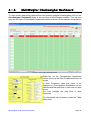
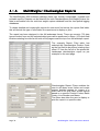
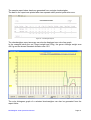
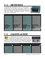
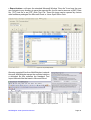
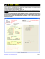
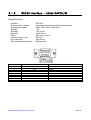
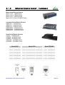
1
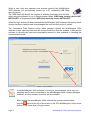
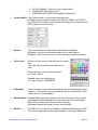
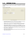
MultiWeigher 3000 00 0 MultiWeigher 3 Weight Information Management System OPERATIONS MANUAL LICENSE The MultiWeigher 3000 software is licensed to the end user to be installed on one computer per individual license. The MultiWeigher software license comes supplied with a single USB License Key that must be fitted to the computer running the MultiWeigher 3000 software. PUBLISHING RIGHTS Axion Control Systems Pty Ltd (AxionCS) reserves the right to make periodic changes, revisions, specification enhancements and alterations of any kind to the product and this manual without obligation to notify any person(s), institution or organisation of such changes, revisions, enhancements and alterations. PUBLISHING DISCLAIMER AxionCS has taken due care in the preparation of this document and every attempt has been made to ensure its accuracy and completeness. In no event will AxionCS, its agents, distributors and representatives be liable for damages of any kind, incidental or consequential, in regards to or arising out of the performance or form of the material presented in this document. ® / ™Trademarks Windows 2000, NT, XP and Vista are trademarks or registered trademarks of Microsoft Corporation. Borland® are trademarks or registered trademarks of Borland Software Corp. All other trademarks or registered trademarks are the property of their respective owners. PRODUCT COMMUNICATIONS AxionCS welcomes your suggestions, comments and feedback about the MultiWeigher 300 and any associated documentation. Please send your written communications to [email protected] PRODUCT SUPPORT For any support requirements please email to [email protected] No part of this publication may be reproduced, copied, transmitted, transcribed, plagiarized, or translated into any language, in any form, by any means without the written permission of AxionCS. Page 2 MultiWeigher 3000 Operations Manual PRODUCT DISCLAIMER The purchase, installation and use of products manufactured or distributed by AxionCS are deemed to be at the Customer's consent to the following conditions: 1. The Customer acknowledges that any advice provided by AxionCS in respect of the use or installation of the Products is given in good faith and the Customer acknowledges that it is solely responsible for deciding whether the Products are appropriate to their proposed installation, situation and intended use. 2. AxionCS disclaims all responsibility for loss and damage arising (including any consequential loss or damage) which may be incurred by the Customer or another party as a result of the use or installation of the Products. 3. The Customer acknowledges that the Products functionality and operability may be limited or suspended until cleared payments in full are received by AxionCS. AxionCS disclaims all responsibility for loss and damage arising (including any consequential loss or damage) which may be incurred by the Customer or another party as a result of such Products limitation. 4. AxionCS makes no warranty whether express or implied in relation to any of the Products or any advice provided in respect of the Products and, to the extent permitted by law, any implied warranty or condition of merchantability, quality or fitness for a particular purpose, is expressly negatived. If conditions and warranties are implied under the Trade Practices Act 1974 and similar legislation and cannot be excluded, AxionCS limits its liability to the extent permitted by law to the re-supply of or (at Axion discretion) to the refund of the purchase cost of the Products. 5. By the use and installation of the Products, the Customer indemnifies and holds harmless AxionCS in respect of any and all claims which may be made against the Customer, AxionCS or others as a consequence of any use or installation of the Products which gives rise to a claim for liability whether made by the Customer or another person or company. 6. Under no circumstances will AxionCS or its suppliers be liable for loss and damage, or for direct, special, incidental, consequential or other damages (including any consequential claim for economic loss), whether based in contract, tort or otherwise arising from the use of the Products. 7. In this Disclaimer, the following expressions shall have the following meanings: - "AxionCS" means Axion Control Systems Pty Ltd (ACN 083 262 711) of Moorabbin Business Park, 56 / 148 Chesterville Road, Cheltenham, post code 3192, in the State of Victoria, Australia and its directors, officers, employees, servants, agents and representatives. - "Customer" means the purchaser or any person and / or company who intends to and uses the Products for the purpose for which they are designed and shall include any person who misuses the products or uses the products for a purpose other than for which they were designed and intended to be used. - "Products" means all products manufactured, distributed and sold by AxionCS, whether installed by AxionCS or by the Customer or by another party. MultiWeigher 3000 Operations Manual Page 3 Contents 1. Features...................................................... 6 2. Hardware Requirements ....................... 7 2.1.1. 2.1.2. 3. 3.1.1. 3.1.2. 3.1.3. 3.1.4. 3.1.5. 3.1.6. 3.1.7. 3.1.8. 3.1.9. 4. 4.1.1. 4.1.2. 4.1.3. 4.1.4. 4.1.5. 4.1.6. 4.1.7. 4.1.8. 5. 5.1.1. 5.1.2. 5.1.3. 5.1.4. Hardware Requirements ........................................................... 7 Hardware - Typical Overview .................................................... 8 MultiWeigher Software .......................... 9 Microsoft Windows Environment ............................................... 9 Keyboard and Mouse Environment ........................................... 9 Launching MultiWeigher.......................................................... 10 MultiWeigher Login Screen ..................................................... 11 MultiWeigher Device Setup ..................................................... 13 MultiWeigher Settings ............................................................. 17 MultiWeigher Passwords......................................................... 21 MultiWeigher Products ............................................................ 23 MultiWeigher Backup and Restore .......................................... 27 MultiWeigher Checkweighers ........... 29 MultiWeigher Checkweigher Screen ....................................... 29 MultiWeigher Checkweigher Simulator ................................... 34 MultiWeigher Checkweigher Dashboard ................................. 35 MultiWeigher Checkweigher Reports ...................................... 36 A&D 4404 Dolphin................................................................... 38 Ishida DACSV and DACSW .................................................... 38 Yamato CE2100 ...................................................................... 39 Anritsu SF and SV series ........................................................ 39 MultiWeigher Scales............................. 40 MultiWeigher Scale Screen ..................................................... 40 MultiWeigher Scale Global Settings ........................................ 42 MultiWeigher Scale Simulator ................................................. 43 MultiWeigher Scale Reports .................................................... 44 6. AQS / UTML .............................................. 47 7. MultiWeigher Debugging ..................... 50 8. Interface Connections ......................... 51 8.1.1. 8.1.2. 8.1.3. Page 4 RS232 Interface – A&D 4404 Dolphin ..................................... 51 Serial Interface RS485/RS422 – A&D 4404 ............................ 52 RS232 Interface - Ishida DACSV/W ........................................ 53 MultiWeigher 3000 Operations Manual 8.1.4. 8.1.5. 8.1.6. 8.1.7. 8.1.8. 8.1.9. RS232 Interface – Yamato CE2100 ........................................ 54 RS232 Interface – Anritsu SF and SV ..................................... 55 Serial Interface Communication Modes .................................. 56 Ethernet Device Server - Hardware ........................................ 57 Ethernet Device Server - Software .......................................... 58 RFID Hardware ....................................................................... 60 Specifications .................................................... 61 9. Index 10. Figures .......................................................... 62 ...................................................... 63 When this icon is present the screen or software has not been finalised and is still under construction. MultiWeigher 3000 Operations Manual Page 5 1. Features MultiWeigher 3000 is designed to run on a Microsoft Windows operating system. The MultiWeigher 3000 software is designed to meet the growing requirements for real-time weight capture, data collation and analysis. MultiWeigher 3000 provides framework and structure for a factory-wide Weight Information Management System (WIMS). The MultiWeigher software is capable of monitoring, checking and grading the weight data of various products that are passed over the connected scales or checkweighers. ; Operating Systems The MultiWeigher 3000 software can run on most Microsoft Operating Systems Windows 2000, NT, XP Professional, XP Home Edition and Vista. ; Visually Appealing The software utilises soft Pascal colors in bold text for the identity of the target, under, over and erroneous weights. OK weights in olive, Under in orange, Over in red and Errors are inverse solid red blocks. ; Various Products The MultiWeigher 3000 can be used to collect weight data from: Platform Scales, Scientific Balances, Weight Indicators, Checkweighers, Counting Scales and other weighing devices. ; Various Protocols The data string input to the computer from the weight scale can be modified to suit any piece of weighing equipment, from any scale manufacturer as long as the scale is fitted with a serial interface. The serial interface can be any one of the following: A) B) C) D) RS232 Serial Output and Serial I/O. RS485 Serial Output and Serial I/O. RS422 Serial Output and Serial I/O. Ethernet TCP/IP, Modbus and Port Address. ; Data Bases The MultiWeigher software package stores its data in a comma delimited text format which can be easily read by products like MS Excel. The data recorded is: Weight, Time, Date, Product, Operator, Station and Errors. These records can either be printed or viewed on the monitor screen. ; Reports Reports can be viewed, printed and sorted by Date, Month, Operator, Product, Table, Station, Transaction, Transaction summary or Custom Extra data fields. ; Checkweighers The MultiWeigher 3000 software as standard can be interfaces to four checkweighers available in today’s market place; however MultiWeigher 3000 can be up-graded to included data capture from any checkweigher with a serial output. Page 6 MultiWeigher 3000 Operations Manual 2. Hardware Requirements 2.1.1. Hardware Requirements Minimum Computer Hardware Requirements • • • • • • • • • • Intel Pentium® 2.2GHz or AMD equivalent Processor 17” TFT Colour Monitor 50 MB Free (minimum install) Hard Drive Space 256 MB Scratch "Temp" space 512 MB RAM 512 MB Virtual Memory Space 32+ MB Graphics Card 10/100 MB Ethernet Multiple USB ports (One port for Security Dongle) CD/DVD ROM Drive Recommended Computer Hardware Requirements • • • • • • • • • • Pentium IV 3.0G+Hz or AMD equivalent Processor 19” TFT Colour Monitor 250GB (100 MB Free Hard Drive Space) 1GB Scratch "Temp" space 1GB RAM 1.5 GB Virtual Memory Space 64+ MB Graphics Card 10/100/1000 Ethernet Multiple USB ports (One port for Security Dongle) CD/DVD ROM Drive Other Hardware Requirements • • • • • Weight Scale/s with Serial RS232/RS485/RS422 Option Fitted Checkweigher/s with Serial RS232/RS485/RS422 Option Fitted Multi-port Serial to Ethernet Device Server (i.e. Sena, Moxa, Lantronix) Serial to Ethernet data cables for each Weight Scale/s. Personal Computer with a running Windows Operating System MultiWeigher 3000 Operations Manual Page 7 2.1.2. Hardware - Typical Overview The typical hardware in a system that the MultiWeigher software will interface to, consist of a personal computer, multi-port serial to Ethernet device server and several scales, indicators, checkweighers or other weighing equipment. There is a practical maximum limit of 255 scales that can be connected at any one time in a single weight data capture system. The scales MUST be capable of either transmitting weight data by manual print button, transmit continuously or the MultiWeigher software can command-request the weight data from the scale if this function is available in the scale. The personal computers will be set at a particular IP address and Subnet mask on the network so it is important to set the Ethernet device server in the same IP and Sub mask range. The Ethernet device server allows for the scales to be set as different serial port data formats i.e. 7, e, 1 or 8, n, 1 on the same network, these settings in the Ethernet device server can either be configured using the Network Enabler Administrator software or by using Windows Internet Explorer or Mozilla Firefox. Page 8 MultiWeigher 3000 Operations Manual 3. MultiWeigher Software 3.1.1. Microsoft Windows Environment As with most MS Windows software programs the insertion of data is predominantly carried out by clicking the data field with use of a mouse or mouse pad, and to a lesser extent by using the keyboard. When the data bases are entered such as operators, products, etc… minor entry of information is carried out via the keyboard. Accessing the relevant areas of the program is undertaken by clicking on the relative folder or tabs. Other software applications such as MS WORD or MS EXCEL can also be operating whilst the MultiWeigher system is in use. The flexibility of MS WINDOWS allows the operator to enter a particular field by simply clicking on that field or folder. These fields and folders will be discussed throughout the manual. In any PC based system it is strongly recommended that periodic backing-up of the data bases is carried out, this avoids losing significant amounts of information in the event of power surge, hardware damage etc… 3.1.2. Keyboard and Mouse Environment When running the program the folders and fields can be accessed by either clicking on the mouse whilst the pointer is over the particular title or by holding the Alt key and typing the underlined first letter (E.g. Alt + F) of the menu group. This opens up the relevant menu and enables the user to further select the relevant area by either using the mouse, the arrow keys on the keyboard or the Alt + letter. The operator will gain experience using a combination of both functions to skillfully move around the screen, enter information and select functions. The ‘TAB’ key moves the focus from one data entry box to the next. The ‘ENTER’ key (like the tab key) moves the focus from one data entry box to the next. The ‘arrow’ keys are used to move around within a data entry box or table. The ‘backspace’ key is used to back over and change the text. MultiWeigher 3000 Operations Manual Page 9 3.1.3. Launching MultiWeigher Double Clicking the MultiWeigher icon on the desktop will launch the MultiWeigher software package. The screen below will be displayed for several seconds while the MultiWeigher software loads all the connected devices configuration parameter, this progress will be displayed by the sliding bar. Figure 1 - MultiWeigher Launching The next screen to be displayed automatically is the Login screen. MultiWeigher 3000 uses three types of inputs for people using the system. User > is one who uses a computer system. In order to identify oneself, a user or username is also called a screen name, handle, and nickname. Password > is a word or string of characters that is entered, often along with a username, into a computer system to log in or to gain access to some resource. Passwords are a common form of authentication. Operator > is a person who performs a function, in this case it is a person who weighs product in a factory commonly called a packer. Page 10 MultiWeigher 3000 Operations Manual 3.1.4. MultiWeigher Login Screen MultiWeigher 3000 data capture software identifies three user levels and their passwords for authentication and protection. Level 1 Operator user name only gains access to the top layer folders; products, checkweighers, scales and reports, the lower layer folders will not be visible. Level 2 Administrator user name has access to the same folders as the operator plus the lower layer folders passwords and backup/restore. Level 3 Technician user name gains full access to both top and lower folders. Operator - Level 1 Administrator - Level 2 Technician - Level 3 Password Required Figure 2 - Login Screen The MultiWeigher 3000 software is NOT active until one of the above user levels and its associated password has been entered correctly. MultiWeigher 3000 Operations Manual Page 11 When a user level and password are entered correctly the MultiWeigher 3000 software will automatically search for a PC connected USB Hasp security device. The USB Hasp will identify the version of software purchased and will also either allow the software to run in Demonstration Mode “USB Hasp security device NOT INSTALLED” or Registered Mode “USB Hasp security device INSTALLED”. When the login button has been pressed the MultiWeigher 3000 software will identify which version has been installed and acknowledges the user and their level of access. The Commence Data Capture button when pressed initiates the MultiWeigher 3000 software to start capturing data from all connected devices that are enabled. It also lets the software to allocate the maximum permissible amount of time available to handling the communication ports. USB Hasp security device found, software version FULL and SERVER Figure 3 - Log on Validation If the MultiWeigher 3000 software is running in demonstration mode only one weighing device can be controlled by the MultiWeigher 3000 software package however, all other software functions will be available. When exiting the MultiWeigher 3000 software the operator should either button at the top of the screen or the “Exit MultiWeigher” button at the use the bottom of the lower layer of Login screen. Page 12 MultiWeigher 3000 Operations Manual 3.1.5. MultiWeigher Device Setup To setup MultiWeigher 3000 the Technician level and password will need to be activated as this level will gains full access to all the MultiWeigher 3000 folders. The first task is to install and configure all connected devices; this is done by using the Devices folder on the lower layer. The devices folder stores all the details for each piece of weighing equipment connected in the field; such as weight scales or checkweighers. [Configuration > Devices] Figure 4 - Device Screen New > clicking on the New button will open the device window. In the device window a user can display All Devices, Used Devices or Unused Devices. Delete > clicking on the Delete button will allow the user to delete the details of the selected device; the name, description, line number, device type, driver will be deleted and this device will be disabled. Undo > when first opening the device folder this button will be grayed out. Clicking on the Undo button will erase all the changes that have just been made for this particular device back to the original details when previously opened. Accept > when first opening the device folder this button will be grayed out. When a change is been made to the device folder the Accept button will become active this will allow the user the Accept the changes made to this particular device. MultiWeigher 3000 Operations Manual Page 13 Save > when first opening the device folder this button will be grayed out. The Save button will only become active after the Accept button has been pressed, this confirms that the changes made to this device need to be stored and saved. Zoom > the zoom button allows the user to view and filter All, Used and Unused devices stored in the system First Record > the First record button when pressed will display all the details for the first device installed; this is also referred to as ID Number 1. Previous > the Previous record button when pressed will display the record details for the device with preceding ID Number from the device the user is now displaying. Next > the Next record button when pressed will display the record details for the following ID Number saved in the device database. Last Record > the Last record button when pressed will display all the details of the last device available, this is also referred to as ID Number 255. • Name This field is to store a unique device name; this will be used in various other folders in MultiWeigher 3000 Characters = 30 Alpha and Numeric • Description This field is to store a complete alpha numeric device description e.g.; A&D EK Scale on Line 1 in Position 1 Characters = 40 Alpha and Numeric • Line Number This field identifies the scales position in a line or on a table. It can also be used as a descriptor for the checkweighers. Characters = 20 Numeric • Table The table field is a drop down selection box MultiWeigher stores a maximum of 240 scales; this allows 12 lines or tables with a maximum of 20 scales on each tables. • Device Type The device type is a drop down selection box. Selectable: Checkweigher, Scale, Multihead Weigher and Key Fob Generator • Driver The driver field is a drop down selection box; drivers available are: • A&D 4404 Checkweigher Controller • A&D 4323 Digital Weight Indicators and Scales • A&D Scales • A&D Indicators • Ishida DACSV Checkweighers with RS232 or RS485 • Ishida DACSW Checkweighers with RS232 or RS485 • Ishida DACSV/W Checkweighers with Stream • Yamato CE2100 Checkweigher with RS232 • Adilam (RFID) Radio Frequency Identification Device Page 14 MultiWeigher 3000 Operations Manual • • • MT 8434 Mettler Toledo mini tiger retail scales SIMSCALES Scales Simulator SIMCHECKWEIGHER Checkweighers Simulator • Comms Mode The comms mode is a drop down selection box Available communication methods are RS232, RS485 and TCP/IP. e.g. If RS232 is selected extra fields will be displayed to obtain the full RS232 protocol requirements • Disable The connected device can either be Enabled or Disabled Disabled = no device connection made and no data capture Enabled = a device connection is made and data capture recorded • Color Code Mouse left-click on the field will open the pallet box. The color field stores the selected device color Default primary colors will be identified e.g. Red = clRed Shaded colors are identified as e.g. Light Orange = $000080FF • ID Number • Rescan Mode Rescan Mode allows the update of all the information of the product captured in the MultiWeigher to be the same as the Checkweigher Manual Only means the rescan is done manually Automatic means the rescan is done automatically • DB Poll The ID number is generated automatically by the MultiWeigher 3000 software. 255 devices are permissible the device breakdown is 240 scales and 15 checkweighers The DB Poll is the switch to Enabled or Disabled MultiWeigher 3000 from storing captured checkweigher weights to the graph database. MultiWeigher 3000 Operations Manual Page 15 • Error Interval The Error Interval field is the fastest weighment speed practical by an Operator. This value is stored in milliseconds and if weights are received in a shorter time period the weighment is recorded as an error. e.g. the operator puts a product on the scale and pressing print several times. Restart Data Capture enables the MultiWeigher to start capturing data from the Enabled devices This icon will be shown at the bottom right of the screen when the MultiWeigher Data Capture is running Page 16 MultiWeigher 3000 Operations Manual 3.1.6. MultiWeigher Settings The MultiWeigher 3000 settings folder stores all the system hardware and software configuration settings and should only be modified by authorized and experienced personnel. [Configuration > Settings > General] Figure 5 - General Settings Screen • Use Virtual Thread allows the user to either select the standard communications thread or a virtual communication thread; tick selects, blank unselects. • Comms Cycle is the maximum time period that MultiWeigher should complete a hardware communications cycle. Time is editable from 100 to 3,000 milliseconds. • Comms Device Interval sets the time period for MultiWeigher to read the checkweigher data stored in the checkweigher controller, the data received is then displayed in the checkweigher folder. Time is editable from100 to 100,00 milliseconds • Day / Afternoon / Night Shift Starts sets the start times of the Day, Afternoon and Night shifts of the production runs • Day / Afternoon / Night Shift Name gives the names for the Day, Afternoon and Night shifts of the production runs MultiWeigher 3000 Operations Manual Page 17 Restart Data Capture enables the MultiWeigher to start capturing data Stop Data Capture enables the MultiWeigher to stop capturing data [Configuration > Settings > Scales] Figure 6 - Scale Settings Screen • Update time to Data Capture is the time period for MultiWeigher to update the weighing scales data capture folder. Time is editable from 5 to 3,600 seconds • Scale Auto Log Off Time is the minimum time period for a scale to perform a complete weighment cycle. Start from zero, apply weight, stabilize and return to zero. Time is editable from 240 to 43,200 seconds • Scale Simulator Standard Deviation is the default Standard Deviation used to run the Scale Simulator • Location Display Enable Page 18 MultiWeigher 3000 Operations Manual [Configuration > Settings > Checkweighers] Figure 7 - Checkweighers Settings Screen • Checkweigher Database Poll Time sets the time interval to which the MultiWeigher software updates its graph database with the Target, Average and Standard Deviation values that are present in the Checkweigher folder at that point in time. This creates important plant production trending. Time is editable from 10 to 3,600 seconds • Auto Rescan Time is the time allowed for MultiWeigher to update information of product captured as the checkweigher. Time is editable from 10 to 3,600 seconds • Use Shift information to record Checkweigher runs allows the user to use the shift information that is set in the General settings to record the checkweigher runs • Reset Batch Field at end of Shift or On Data Reset enables the reset of data of a specific product batch at the end of a shift • Average Over Time or Sample gives the option of showing Average over a period of time or a number of samples on the Checkweigher folder. The period of time and the number of samples is editable by the user • Default Checkweigher Standard Deviation for Simulator Mode is the default Standard Deviation used in the checkweigher simulator MultiWeigher 3000 Operations Manual Page 19 [Configuration > Settings > AQS / UTML] Figure 8 - AQS / UTML Settings Screen • Enable Assistance Tool for Regulations Compliance enables the use of the AQS tools during the scale and checkweigher simulations when the Enable box is checked Page 20 MultiWeigher 3000 Operations Manual 3.1.7. MultiWeigher Passwords The MultiWeigher 3000 Password folder is only accessible by the Level 2 Administration and Level 3 Technician user names; the Level 1 Operator user name does not have access to this folder, so it will not be displayed. The password folder allows the user to Create, Modify and Delete operators and their associated passwords plus the ability to set the level for the user’s password. The password folder also gives the user the ability to assign an RFID tag or key to any of the operators stored in the MultiWeigher 3000 database. The RFID number is obtained automatically from a connected and device allocate reader, the number if known can also be entered manually. A correct RFID number will typically look like “07348C6C8D; this is a unique registered 10 digit 256 bit encrypted number. [Configuration > Passwords] Figure 9 - Password Screen • Create User button allows the administrator to enter user names, user passwords and the user’s payroll numbers. These data fields are required for each and every user whom will be utilizing the data capture system • Modify User Password button allows the administrator to modify existing user passwords if they need to be changed for operational or security reasons. The correct users name and original password will need to be verified first before a change can occur. • Delete User button allows the administrator to remove users and their details from the MultiWeigher database. This is normally performed when a user leaves the place of employment. MultiWeigher 3000 Operations Manual Page 21 • Add RFID Code to User allows the administrator to allocate RFID key fobs or RFID wristbands to a user that will be using the weighing equipment in the factory. The RFID code is 128Bit encrypted for security purposes and cannot be reproduced to another key fob or wristband. • View/Edit User List allows the administrator to easily view the registered system user and their specific user details. It also gives the administrator the ability to edit the registered user’s details. Also from within this screen the administrator can insert new users into the system database. This screen simplifies the addition on users by combining both the Create User and Add RFID screens into the one-hand edit screen. Figure 10 - Operators Screen Page 22 MultiWeigher 3000 Operations Manual 3.1.8. MultiWeigher Products MultiWeigher 3000 software can store a total of 250 products in its database. To add a new product to the MultiWeigher database, select the Products folder on the top layer of the screen, then press the Insert button and fill in the required data fields. Figure 11 - Product Screen Insert > clicking on the Insert button will clear the product folder and allows the user to enter a new product information and its characteristic details. Delete > clicking on the Delete button will allow the user to delete the active product from the database; the name, code, and product details will be deleted and this product will be disabled. Undo > when first opening the device folder this button will be grayed out. Clicking on the Undo button will erase all the changes that have just been made for this particular product back to the original details when previously opened. Accept > when first opening the device folder this button will be grayed out. When a change is been made to the product folder the Accept button will become active this will allow the user the Accept the changes made to this particular product. MultiWeigher 3000 Operations Manual Page 23 Save > when first opening the device folder this button will be grayed out. The Save button will only become active after the Accept button has been pressed, this confirms that the changes made to this product need to be stored and saved. Search > the search button allows the user to view all products stored in the database, and the ability to then select a product for modification or deletion. First Record > the First record button when pressed will display all the details for the first device installed, this is also referred to as Line Number 1. Previous > the Previous record button when pressed will display the record details for the device on the line preceding the device the user is now displaying. Next > the Next record button when pressed will display the record details for the next device saved in the device database. Last Record > the Last record button when pressed will display all the details of the last device available, this is also referred to as Line Number 255. • Product Name This field is to store the Scale products short name and it will be used in various reports throughout MultiWeigher Characters = 12 Alpha and Numeric • Product Code This field is to store a unique short Scale product locator or number Characters = 4 Numeric • Checkweigher Product Name This field is to store the Checkweigher products short name and it will be used in various reports throughout MultiWeigher Characters = 12 Alpha and Numeric • Checkweigher Product Code This field is to store a unique short Checkweigher product locator or number Characters = 4 Numeric • Prod Description This field is to store a fully detailed products description Characters = 40 Alpha and Numeric • Prod Enabled This field is to activate or deactivate a product. Enable or Disable • Product Target This field is to store the product target weight Characters = 6 Numeric • Product SG This field is to store the specific gravity of a product. SG = 1 if there is no special required specific gravity • Product Units This field is to store the unit of a product. Selections are grams, kg, tonnes, ml and litres Page 24 MultiWeigher 3000 Operations Manual • Product Pouch Size (mm) This field is to store the pouch size of a product • Product Line Number • Tolerances This field is to store the line number of a product There are four fields to enter target weight tolerances; they are LoLo, Lo, Hi, and HiHi These values are checked as weight value is not equal to set weight target Characters = 4 Numeric Update CW Codes updates the Company Product Name and Description into the Checkweigher data and vice versa Import Products enables user to import product information from a text file Import file format can be Comma, Tab or Space Text File to be imported Fields to be imported Figure 12 - Import Product Screen MultiWeigher 3000 Operations Manual Page 25 Right-click on the Product window enables users to transfer the Product information into a selected Checkweigher This function can also be used to recall the product code to be run by the Checkweigher Send Product Code information and additional setpoints to the selected Checkweigher. Also to recall Product Code to be run by the selected Checkweigher (In this example, Product Code = 0004) Figure 13 - Send Data Screen Additional setpoints: Pre Tare, Full Filling, Zero Band, and Target Count can also be added into a selected AD4404 Checkweigher Products can also be added to the MultiWeigher database automatically from the checkweigher screen by right mouse clicking on the name field as below. Add Product Code to Database Transfer Checkweigher Setpoints to Database Transfer Product Code Setpoints to Checkweigher Page 26 MultiWeigher 3000 Operations Manual 3.1.9. MultiWeigher Backup and Restore At the end of a Week, Month or Year the active databases can be archived and stored for future analysis; these created user files are known as Archived Database. The archived database can be saved in any directory under any permissible windows file name on the MultiWeigher hard drive, backup drive or connected network server drive. The databases that can be backed up are Checkweigher Active Database, Checkweigher Log Database, Scale Data Capture Database and the MultiWeigher Main Database. There is only one database that can be restored in case of hardware failure and that is the MultiWeigher main database. Figure 14 - Backup and Restore Screen Backup database procedure First select the function you require to be performed, then if required tick the archive box and select a date to archive up to, this function allows the user to archive last weeks data and not effect the present weeks data being captured in the active database. MultiWeigher 3000 Operations Manual Page 27 Press the start button, MultiWeigher will then open the standard Microsoft Window “Save As”. From this window the user can select a previous file name and location or type in a new archived file name and file location. e.g. 19-08-2008 CW Database.gbk Restore database procedure Only restore the database if the MultiWeigher software is updated to a newer version and the previously backed up database need to be restored in the newer version software. You can also restore database if the current database is corrupted as shown in the warning message below. Read the warning instruction properly and do everything it asks before continue the database restore. Figure 16 - Restore Screen Click Yes to continue and a standard Microsoft Window “Open” will open. Choose the database file to be restored Page 28 MultiWeigher 3000 Operations Manual 4. MultiWeigher Checkweighers 4.1.1. MultiWeigher Checkweigher Screen To view the live real-time data being captured from the connected checkweighers click on the top layer Checkweigher folder; this will then open the low layer checkweigher folders as can be seen in the example image below. If the data capture has been activated in the [Configuration > Login] screen or the Device folder, the Comms Status field will display either [ Comms Good! ] or [ Comms Failure! ]. Figure 16 - Checkweigher Screen • AQS Tool Clicking on the AQS Tool button will open up the AQS / UTML Compliancy test during the Checkweigher Simulation • Update CW Codes Clicking on the Update CW Codes button updates the Product Code information in the Multiweigher to be the same as the checkweigher MultiWeigher 3000 Operations Manual Page 29 • Product Code and Name These fields store the checkweigher Product Code and Name being captured by the MultiWeigher These fields are writable by the user • Total Weight and Units These fields store the total weight and its unit of the checkweigher product being captured These fields are NOT writable by the user • Line Number This field stores the production Line Number of the checkweigher being captured This field is NOT writable by the user • Batch No. This field stores the Batch Number of the checkweigher product being captured This field is writable by the user • Comms Status This field notifies the user if the Communication between the Device and the MultiWeigher is established This field is NOT writable by the user • Description This field stores the Description of the checkweigher product being captured This field is NOT writable by the user • Targets Tare This field stores the Tare value of the captured product needs to achieve its targeted net weight This field is writable by the user Target This field stores the Target value that needs to be achieved by the captured product This field is writable by the user Zero Band This field stores the Zero Band that captured product needs to initialized its weighing This field is writable by the user Full Filling This field stores the Full Filling value of the captured product indicating that the product is fully filled This field is writable by the user • Limits The fields under Limits store the LoLo, Lo, Hi, and HiHi limits for the judgment of the product being weighed These fields are writable by the user • Stats Min and Max These field store the Minimum and Maximum weights of the captured checkweigher product These fields are NOT writable by the user Page 30 MultiWeigher 3000 Operations Manual Average This field store the overall Average weight of the captured checkweigher product This field is NOT writable by the use Average Over Last __ Minute / Samples stores the Average weight over a period of time or over a number of samples. The numerical number of minute and sample is writable by the user This Average field is NOT writable by the user STD This field stores the Standard Deviation of the captured checkweigher product This field is NOT writable by the user STDP This field stores the Population Standard Deviation of the captured checkweigher product This field is NOT writable by the user • Start Clicking on the Start button will initiate MultiWeigher to transmit the serial start command via the connected communication method to a particular checkweigher controller. The checkweigher receiving this command will switch from stop mode to run mode; all the connected conveyors and associated equipment will run • Stop Clicking on the Stop button will initiate MultiWeigher to transmit the serial stop command via the connected communication method to a particular checkweigher controller. The checkweigher receiving this command will switch from run mode to stop mode; all the connected conveyors and associated equipment will stop • Clear Totals Clicking on the Clear Totals button will initiate MultiWeigher to transmit serial clear totals command via the connected communications method to a connected checkweigher controller. There will be a short lapse in time while the checkweigher controller writes all stored values back to zero; the MultiWeigher software should now display all zeros in the counts and stats fields. • Rescan Code Number The Rescan Code Numbers button allows the user to force the software to rescan the checkweigher controller in the field. This would normally be done to verify what is the actual product code has been set in the controller to be check. If the rescan does verify that the checkweigher has been changed to another product, the software will from now on monitor this updated product code. MultiWeigher 3000 Operations Manual Page 31 • Write Mode Enabled Changing or writing new data to the checkweigher controller is done simply by placing a tick (√) in the Write Mode Enable box (□); this will then switch the software from Data Capture mode in to Data Edit mode. • Write When the user has adjusted/changed the required data fields, the user will need to click on the Write button; this instructs the software to re-send all the information on the screen to the A&D Dolphin checkweigher controller. • Export The Export Data button in the software allows the user to save the recorded/displayed data in a Microsoft Excel txt file in Tab Delimited Format. The file can be named in any format that suits the user; this is for easy retrieval at a later date for data manipulation and reporting. • EStop Clicking on the EStop button will initiate MultiWeigher to transmit the serial Emergency Stop command via the connected communications method to a particular controller Checkweigher This will force the checkweigher controller to turn off all of its outputs immediately, all connected equipment will stop. • Graph Clicking on the Graph button will open the Graphical Trend page. Checkweigher Trend Graph The trend graph displays the instant real-time weighment data captured from the selected checkweigher. This enables the user to see at a glance if the plant is producing products at the correct weight or to analyze where possible faults may have arisen (please refer to Page 32). Page 32 MultiWeigher 3000 Operations Manual Figure 17 – Checkweigher Line Trend Graph • Histogram Pressing the Histogram button will open the Trend Histogram page. MultiWeigher 3000 Operations Manual Page 33 4.1.2. MultiWeigher Checkweigher Simulator To create a Checkweigher Simulator, select the SIMCHECKWEIGHER driver in the Devices setting. When the simulator device is enabled, a checkweigher simulator is created as shown in the screen below. Figure 18 - Checkweigher Simulator Screen Before starting to run the Checkweigher Simulator, it needs to be set up. The main fields that need to be set are the Target, LoLo, Lo, Hi, HiHi, STD, Total Counts When filling in the main fields, the Write Mode needs to be enabled After the setup, press the until the Total Counts is achieved Click on the Click on the Page 34 button to start the simulator. The simulator will self-run button to clear all the totals before starting the simulator again button to view the AQS compliancy test simulation MultiWeigher 3000 Operations Manual 4.1.3. MultiWeigher Checkweigher Dashboard To view certain data being captured from the multiple enabled checkweighers click on the Checkweigher Dashboard folder at the top layer of MultiWeigher window. This will then open the low layer Checkweigher Dashboard screen as shown in the example image below. To Print the Summary of CW Dashboard Figure 19 - Checkweigher Dashboard Screen Right-click on the Checkweigher Dashboard screen opens up the Area Properties window as shown. In Area Properties, data that need to be displayed in Checkweigher Dashboard can be selected and the width size of each row can also be set. The color settings can also done in Area Properties The dashboard can be named under the Table Name field MultiWeigher 3000 Operations Manual Page 35 4.1.4. MultiWeigher Checkweigher Reports The MultiWeigher 3000 software package offers user friendly configurable, viewable and printable reports. Reports can be obtained for both Checkweighers and Weight Scales; the data is retrievable from the real-time weight capture database and the time polled logging databases. To obtain detailed and meaningful reports the user must first set-up the reports field table; this will decide the type of information the reports are to display or print. The report has been designed in the A4 landscape format. There are seventy (70) data types to select from and the selected data types can be positioned in fifteen (15) report field locations starting from the far left side of the page across the top of an A4 landscape report. The example Report Field table has selected the Checkweigher Product Code as the first field to be printed, starting from offset “0” from the far left of the printed A4 Landscape checkweigher report as per example on the next page. Figure 20 - Report Fields Screen Checkweigher Report Filters enables the user to drill down even further and create custom detailed reports by means of a Start Date to an End Date, create reports based on a specific Product Codes, Batch Codes, Line Number and Name. The filters also allow the user to display or print the report in a specific order. Figure 21 - Report Filter Screen Page 36 MultiWeigher 3000 Operations Manual The sample report below has been generated from a single checkweigher. The data in the report was printed after two separate short product production runs. Figure 22 - Checkweigher Report The checkweigher report summary can also be displayed as a color line graph. In the example below the red Target weight was 500g, the green Average weight was 496.1g and the brown Standard deviation was 15.5. The color histogram graph of a selected checkweigher can also be generated from the report folder MultiWeigher 3000 Operations Manual Page 37 4.1.5. A&D 4404 Dolphin The MultiWeigher 3000 software can be set to automatically or manually poll the A&D 4404 checkweigher controller, the frequency at which the polling operates is stored in the settings folder. The following are the data fields that are received from the A&D 4404 Dolphin checkweigher controller, and their equivalences in MultiWeigher Data from A&D 4404 Dolphin A&D 4404 Data MultiWeigher Data Code Number Product Code Target Target Lo Lo LoLo LoLo Full Full Filling Target Count Target Count OK Count OK Count Hi Count High Count HiHi Count High High Count Metal Detection Metal Count Crush Count Crush Count Minimum Min Standard Deviation STD Total Weight Total Weight 4.1.6. A&D 4404 Data Code Name Hi HiHi Zero Band Preset Tare Total Count NG Count Lo Count LoLo Count Duplication Count Maximum Average Population Std. Dev MultiWeigher Data Name Hi HiHi Zero Band Tare Total Counts Reject Count Low Count Low Low Count Duplication Count Max Average STDP Ishida DACSV and DACSW The MultiWeigher 3000 software can be set to automatically or manually poll the Ishida DACSV and DACSW controllers, the frequency at which the polling operates is stored in the settings folder. The following are the data fields that are received from the Ishida DACSV and DACSW checkweigher controllers, and their equivalences in MultiWeigher Data from Ishida DACSV / DACSW Ishida DACS Data MultiWeigher Data Product Code Product Code Reference Weight Target Lower Weight Lo Minimum Weight Min Total Weight Total Weight Over Count High Count Metal Count Metal Count Page 38 Ishida DACS Data Product Name Upper Weight Tare Weight Maximum Weight Accept Count Under Count Total Count MultiWeigher Data Name Hi Tare Max OK Count Low Count Total Count MultiWeigher 3000 Operations Manual 4.1.7. Yamato CE2100 The MultiWeigher 3000 software can be set to automatically or manually poll the Yamato CE2100 controllers, the frequency at which the polling operates is stored in the settings folder. The following are the data fields that are received from the Yamato CE2100, and their equivalences in MultiWeigher Data from Yamato CE2100 Yamato CE2100 Data MultiWeigher Data Program Number Product Code Target Weight Target Low Weight Lo Low-low Weight LoLo Maximum Weight Max Average Weight Average Weight Under Packs Low Count LL Packs Low Low Count Metal Metal Count 4.1.8. Yamato CE2100 Data Product Name High Limit High-high Limit Tare Weight Minimum Weight Accept Packs Over Packs HH Packs Total Weight MultiWeigher Data Name Hi HiHi Tare Min OK Count High Count High High Count Total Weight Anritsu SF and SV series The MultiWeigher 3000 software can be set to automatically or manually poll the Anritsu SF and SV controllers, the frequency at which the polling operates is stored in the settings folder. The following are the data fields that are received from the Anritsu SF and SV controllers, and their equivalences in MultiWeigher Data from Anritsu SF / SV Anritsu SF/SV Data MultiWeigher Data Product Number Product Code Reference Weight Target -NG Limit Lo Standard Deviation (s) STD -NG Count Low Count MDNG Count Metal Count Total Count Total Counts MultiWeigher 3000 Operations Manual Anritsu SF/SV Data Product Name +NG Limit Tare Weight Pass Count +NG Count Double Prod Count Total Weight MultiWeigher Data Name Hi Tare OK Count High Count Duplication Count Total Weight Page 39 5. MultiWeigher Scales 5.1.1. MultiWeigher Scale Screen The MultiWeigher 3000 software can be set to automatically or manually poll the connected weight scales, the frequency at which the polling operates is stored in the settings folder. The following are the data fields and their character lengths that are received from the A&D EW scales. Figure 23 - MultiWeigher Scale Screen • Operator The operator name is retrieved from the database by either automatically by the RFID key or by the user manually • Status The status of Out to OUT or In to IN is generated automatically by the presentation of the RFID key fob or by the user clicking the empty box • Dev The Dev or Device number is the position or entry that this device has been allocated in the device folder, the value is from 1 to 255. • Batch Code The batch code number is a 12 character alpha-numeric user entry data field, this helps MultiWeigher identify and track the products being packed. Page 40 MultiWeigher 3000 Operations Manual • Prod Code The Product Code is the code number stored in the checkweigher controller, this number is a unique number typically from 01 to 99 designed to verify what product is being check weighed. • Time The Time field is the exact time the last weighment had been received for this particular scale device, the weights are transmitted from the scale by the operator pressing the print button. • Weight The weight field is the last weighment received for this particular scale, the weights are transmitted from the scale by the operator pressing the print button. • Target The target field is the correct or perfect product weight that has been stored in the checkweigher controller, this value will typically be the gross weight which includes the container tare weight and product net weight • Total Weight The total weight field stores the running total value of the received transmitted consecutive weighments made by the operator using this particular scale. • Average The average weight field stores the value obtained from dividing the total weight by the total number of weighments made. • Total The total field stores the quantity or amount of weighments that have been made by the operator. • OW The Over Weight field stores the quantity of weighments made by the operator that exceed the correct weight, these include the Hi and HiHi weighments. (i.e. Target 150g +2g = Hi and +5g = HiHi). • UW The Under Weight field stores the quantity of weighments made by the operator that are less than the correct weight, these include the Lo and LoLo weighments. (i.e. Target 150g -2g = Lo and -5g = LoLo). The Table Properties window is accessed by right mouse clicking on any position from with in the scale table screen. It is not necessary to be on a specific table that you wish to change as there is a drop down box for table selection from 1 to 12. The Table Properties function is to allow the user to customize fonts and colors to suit their specific needs and clarity. An example of this could be Hi weights displayed in red or OK weights displayed in green. MultiWeigher 3000 Operations Manual Page 41 5.1.2. MultiWeigher Scale Global Settings Changing user data fields during the scale data capture operation is possible in MultiWeigher 3000, the software allows for the fields of Operator, Batch Code and Product to be changed, this function is activated by right mouse clicking on the specific data filed requiring the change. A drop down box will appear and allow the user to select for example another Operator, this can also be used if the RFID system is not incorporated or the operator looses his keyfob or this scale has a faulty RFID receiver. The Batch Code field also offers the functions of setting a batch code for all scale in this particular table or all scales in all tables The Product Code field also offers the functions of setting a product code for all scale in this particular table or all scales in all tables Page 42 MultiWeigher 3000 Operations Manual 5.1.3. MultiWeigher Scale Simulator To create a Scale Simulator, select the SIMSCALE driver in the Devices setting. When the simulator device is enabled, a scale simulator is created in table as shown in the screen below. The example below shows three scale simulators that run simultaneously. Figure 24 - Scale Simulator Screen Check in the Operator by checking on the Status OUT box; the status changes to IN and the scale simulation for the checked in operator will start automatically. Click on the button to view the AQS compliancy test simulation MultiWeigher 3000 Operations Manual Page 43 5.1.4. MultiWeigher Scale Reports Selecting the top layer Reports tab and the lower layer tab Scales the user can produce custom reports for all the packing scales in the factory. The weighing data that has been captured from these scales is stored in the Active database as seen below (Figure 11) Figure 25 – Scale Report Screen • Filter Button > is used to custom drill down in to the data for specific reports. The captured data can be filtered down by a simple selection of one or more specific fields that the report needs to contain. E.g.: should the user require a report for a specific days work, for a specific product and weighed by only one operator for one customers batch code this can be selected as shown in the example on the le Page 44 MultiWeigher 3000 Operations Manual • Export button > will open the standard Microsoft Window “Save As” from here the user can navigate to any directory to save the exported file, the file can be save as a (DAT) Data file, (TXT) text file or an (RTF) Rich Text File. These file types can be opened by various other software packages like Microsoft Excel or Linux Open Office Calc. Figure 26 - Export Report Data Opening exported files from MultiWeigher is simple because MultiWeigher saves the exported data as a delimited file this satisfies the standard Text Import Wizards like that used in Microsoft Excel. Figure 27 - Microsoft Excel – Open Exported File MultiWeigher 3000 Operations Manual Page 45 • Printed Report > Clicking on the Printed Report allows the user to view the report of the information captured from the enabled scale Figure 28 - Scale Report Page 46 MultiWeigher 3000 Operations Manual 6. AQS / UTML From 1 July 2010, manufacturers and packers will be able to apply the Average Quantity System (AQS) as their measurement systems. To know more about the AQS system, please visit: http://www.measurement.gov.au/TradeMeasurement/Business/Pages/AverageQuantitySy stem.aspx The AQS Tool of the MultiWeigher 3000 is used with the Scale / Checkweigher Simulators to show the users the difference in product savings using the Average Quantity System (AQS) and the existing Uniform Trade Measurement Legislation (UTML) in their manufacturing / packing environment. Device to be monitored Tick to starts monitoring Figure 29 - AQS Simulator Screen MultiWeigher 3000 Operations Manual Page 47 The first half on the left hand side of the AQS screen shows the 3 rules that need to be fulfilled to comply with the AQS. The other half on the right hand side of the screen shows the 2 rules that need to be fulfilled to comply with the UTML. ¾ AQS Weighted Average Compliancy • Target Weight The Target Weight is the weight that needs to be achieved by the monitored product This value is editable by the MultiWeigher user • Nominal Weight The Nominal Weight is the weight marked on the end-user / customer package of the monitored product This value is editable by the MultiWeigher user from the Set Nominal Weight field • Weighted Average The Weighted Average is the result of the Sample Average added to the multiplication result of the Sample SD with the Sample Correlation Factor • Min Weighted Ave Min Weighted Ave is minimum weighted average being recorded • Total Counts Total Counts is total number of products being weighed or produced in a certain production run • Passed Counts Passed Counts is the number of products that weigh the same as the Nominal Weight • Max Weight Max Weight is the maximum weight of the sample products • Min Weight Min Weight is the minimum weight of the sample products T1 Error Compliancy • T1 Value T1 Value is the Tolerable Deficiency allowed to meet the AQS standard • T1 Counts T1 Counts is the number or shortfall of products allowed to meet the requirement of the T1 Error rule • T1 Rejects T1 Rejects is the number of rejects needed to comply with the T1 Error rule T2 Error Compliancy • T2 Value T2 Value is a value double the T1 value Page 48 MultiWeigher 3000 Operations Manual • T2 Counts T2 Counts is the total number of products that need to be rejected to meet the T2 Error rule • Reject Weights Reject Weights is the total weights that have been rejected to comply with the T2 Error requirement ¾ UTML Average Compliancy • Target Weight The Target Weight is the weight to be achieved by the products in a production run • Nominal Weight The Nominal Weight is the weight marked on the end-user / customer package of the monitored product. It needs to be achieved by the average weight of the monitored product to meet the UTML rule requirement This value is editable by the MultiWeigher user from the Set Nominal Weight field • Average Weight The Average Weight is average weight from a batch of production run of the monitored products 5% Deficiency Compliancy • Reject Counts Reject Counts is the number of products that need to be rejected to meet the requirement of the 5% Deficiency rule Savings Savings show the manufacturers the amount of products they could save (in percentage) by implementing the AQS standard comparing to the existing UTML standard that they have been implementing in their manufacturing processes MultiWeigher 3000 Operations Manual Page 49 7. MultiWeigher Debugging MultiWeigher makes available to experienced technicians a live on screen debugging terminal interface, from this debug screen all the serial traffic flow can be viewed and therefore diagnosed for errors and correct interfacing. The technician will enable the data view and select a specific device that needs to be monitored, the communications ports can be stopped and restarted and the data view window can be cleared at any time. If a checkweigher device is selected as in Figure 18 below; both the read & reply and the write & reply data commands can be viewed in the debug window. Figure 30 - Debug (Checkweigher) Screen If a scale device is selected as in figure 19 below, the technician can identify the serial communications port being used and the RFID tag that was presented. Scale weight data packets can also be seen and confirmation that MultiWeigher has logged this scale off automatically for lack of activity or weighments. Figure 31 - Debug (Scale) Screen Page 50 MultiWeigher 3000 Operations Manual 8. Interface Connections 8.1.1. RS232 Interface – A&D 4404 Dolphin The RS-232C is used to connect to either an Ethernet Hub or Personal Computer. When installing a serial option only one option can be installed at any one time. Specifications Transmission system Data length Start bit Parity bit Stop bits Baud rate EIA RS-232C, Asynchronous, bi-directional, half-duplex 7 bits ot 8 bits 1 bit Odd, Even, not used 1 bit, 2 bits 1200 bps, 2400 bps, 4800 bps, 9600 bps, 19200 bps Connection INSIDE INDICATOR 25 14 13 FG 1 Fix screw SG 1 FG 2 TXD 3 RXD 4 RTS 5 CTS 6 DSR 7 SG 20 DTR Settings of Parameters Refer to the relevant checkweigher controller Instruction Manual. MultiWeigher 3000 Operations Manual Page 51 8.1.2. Serial Interface RS485/RS422 – A&D 4404 The RS-422/485 interface can use commands to control the indicator. The interface can read weighing data or parameters or store parameters to the indicator. The interface can connect a maximum of 32 units and a personal computer. The unit can be specified by an address appended to the command. RS-485 can use 2-wire or 4-wire. Specifications Transmission system Data length Start bit Parity bit Stop bits Baud rate Line Connection Character code Terminator EIA RS-422 / 485, Asynchronous, bi-directional, half-duplex 7 bits or 8 bits 1 bit Odd, Even, not used 1 bit, 2 bits 600 bps, 1200 bps, 2400 bps, 4800 bps, 9600 bps, 19200 RS-422: 4 wires RS-485: 2 wires or 4 wires Max. 32 units ASCII code CR, CR LF Connection INSIDE INDICATOR Terminator switch SDA 1 SDA SD SDB 422/485 RDA RDB 2 SDB TERMINATOR 100Ω DE/RE 3 RDA SG 4 RDB FG 5 SG 6 FG RD Fix screw FG Page 52 MultiWeigher 3000 Operations Manual 8.1.3. RS232 Interface - Ishida DACSV/W Specifications Interface Sychronization method Transmission speed Start bit Stop bits Data bits Parity Communication code Error detection Data transmission direction PIN 1 2 3 4 5 6 7 8 9 RS-232C Intermittent synchronous (Non-Synchronous) 2400, 4800, 9600, 19200 bps 1 bit 1 bit, 2 bits 7 bits, 8 bits Odd, Even, None JIS 8 bit Sum check Bi-directional PIN NAME DCD RxD TxD DTR GND DSR RTS CTS RI MultiWeigher 3000 Operations Manual REFERENCE Not wired Input Output Short-circuited with Pin No. 5 Short-circuited with Pin No. 4 Short-circuited with Pin No. 8 Short-circuited with Pin No. 7 Not wired Page 53 8.1.4. RS232 Interface – Yamato CE2100 Specifications Communication Method Transmission Method Transmission Standard Transmission Distance Transmission Rate Transmission Character Code Start Bit Data Bits Parity Stop Bits Half duplex Bit serial Asynchronous, start/stop RS232C 15m (Max.) 1200, 2400, 4800, 9500 bps ASCII 1 bit 7 bits, 8 bits None, Even, Odd 1 bit, 2 bits Data may not be transmitted from the computer if CTS and RTS of the computer are not connected. Please check your computer manual Transmission Std. RS232C Page 54 Code FG RxD TxD CTS RTS GND Pin Number 1 2 3 8 7 5 Signal Name Frame Ground Receiving Data Transmitting Data Transmitting Enable Receiving Enable Ground Output/Input Input Output Input Output MultiWeigher 3000 Operations Manual 8.1.5. RS232 Interface – Anritsu SF and SV MultiWeigher 3000 Operations Manual Page 55 8.1.6. Serial Interface Communication Modes A&D AD4404 Indicator Stream Mode The data is output on each display update. If the data cannot be output completely due to a slow baud rate, the data is output at the next update. Auto Print Mode The data is automatically printed on batch finish. Manual Print Mode When the preset print key is pressed or the assigned terminal is connected, the data is output. Command Mode This mode is used to control the indicator, to store parameters and to read data or parameters. Page 56 MultiWeigher 3000 Operations Manual 8.1.7. Ethernet Device Server - Hardware Moxa Serial Device Servers Nport 5110 – 1 RS232 Port Nport 5210 – 2 RS232 Ports Nport 5410 – 4 RS232 Ports Nport 5610 - 8 and 16 RS232 Ports Lantronix Serial Device Servers UDS1100 – 1 RS232 Port UDS2100 – 2 RS232 Ports EDS4100 – 4 RS232 Ports EDS008PR – 8 RS232 Ports EDS016PR – 16 RS232 Ports EDS032PR – 32 RS232 Ports Sena Serial Device Servers LS100 – 1 RS232 Port STS400 – 4 RS232 Ports STS800 – 8 RS232 Ports STS1600 – 16 RS232 Ports STS3200 – 32 RS232 Ports Nport 5610 PIN RS-232 1 2 3 4 5 6 7 8 DSR RTS GND TxD RxD DCD CTS DTR Nport 5630 PIN RS-422/485-4w RS485-2w 1 2 3 4 5 6 7 8 MultiWeigher 3000 Operations Manual --------TxD + TxD RxD RxD + GND ----- ----------------Data + Data GND ----- Sena STS1600 PIN RS-232 1 2 3 4 5 6 7 8 CTS DSR RxD GND DCD TxD DTR RTS Page 57 8.1.8. Ethernet Device Server - Software The Serial to Ethernet device servers can normally be configured and setup by various software methods, these can include Telnet, Console, Web browser and Manger software. The manager software can be set to automatically search for an Ethernet connected device server thus making easier to locate if the IP address is not known. The examples in Figures 18 and 19 show the Sena HelloDevice Manager and Moxa Nport Administrator software have both located a their respective four port device servers. Figure 32 - SENA HelloDevice Manager Figure 33 - MOXA NPort Administrator Page 58 MultiWeigher 3000 Operations Manual The examples in Figures 21 and 22 show the Sena and Moxa WEB browser interface using Microsoft Internet Explorer. When the device server IP address is entered into the WEB browsers address bar you will be prompted to enter and User Name and Password. For a Sena device the default logins for User Id is “root” and for a Password is “ADM” For a Moxa device the default logins for User Id is “root” and for a Password is also “ADM” Figure 34 - SENA Web Browser Figure 37 - MOXA Web Browser MultiWeigher 3000 Operations Manual Page 59 8.1.9. RFID Hardware Radio frequency identification (RFID) is an automatic identification method, relying on storing and retrieving data using devices called RFID tags or transponders. An RFID tag is an object that can be applied to or incorporated into a product, animal, or person for the purpose of identification using radio waves, some tags can be read from several meters away and beyond the line of sight of the reader There are many types of RFID tags and these can be either passive or active devices, we will however concentrate on two tags the Key fob and the Wristband The MultiWeigher 3000 software can assign an operator a Key fob as their unique identification for automatic logging on and logging off the system. The key fob is a passive device and does not store any personal information, it simply transmits a 256bit encrypted number when it is in proximity to the reader house in side the weighing scale. The tear shape Key fob features are: Dimensions: W31mm x L40mm x T4.8mm Material: polycarbonate Environmental protection: IP 67 Operating temperature: -25°C to 50°C Colors: Black, Red, Blue The Wristband features are: Page 60 Dimensions: L247mm x W16mm x T1.4mm Chlore 0.6 mg/1 (Norm SIA 385/1) Environmental protection: IP 68 Operating temperature: -25 to +50°C Colors: Black, Dual Colors (Pantone 541C) MultiWeigher 3000 Operations Manual Specifications General Software Version Software Development Operating Systems MultiWeigher 3000 Ver 1.0 for Windows Borland C++ Windows 2000, NT, XP and Vista in 2009 Device Servers Ethernet Modes Supported IP Set-Up 1, 2, 4, 8, 16 and 32 devices communication ports Auto Detecting 10/100/1000 Mbps TCP Server, TCP Client, UDP and Real Comm Web Browser, Telnet, Console, Device Manager Maximum Scales Serial Interfaces Baud Rates 255 Scales in one complete system RS232C, RS422 and RS485 1200 up to 230K Baud Databases Passwords Operator 25 Alpha and Numeric Characters Limited acess Weight data capture ONLY Administrator 16 Alpha and Numeric Characters Full access Editing & Weight data capture Operators Codes : Names : Payroll : Short Name: Name: Weight : Tolerance: Products Reports 16 Alpha and Numeric Characters 32 Alpha and Numeric Characters 16 Alpha and Numeric Characters 16 Alpha and Numeric Characters 32 Alpha and Numeric Characters 16 Alpha and Numeric Characters 16 Alpha and Numeric Characters Operators, Products, Transactions, Transaction summary, Error Reports and Groupings Checkweigher Data Code number – RCOD + 4 Hi – 7 LoLo – 7 Preset Tare – 7 OK Count – 7 Lo Count – 7 Metal Detection – 7 Maximum – 7 Standard Deviation – 7 Code Name – 12 + 3 spaces Lo - 7 Zero Band – 7 Target Count – 7 NG Count – 7 HiHi Count – 7 Duplication Count – 7 Minimum – 7 Population Standard deviations – 7 MultiWeigher 3000 Operations Manual Target – 7 HiHi – 7 Full – 7 Total Count – 7 Hi Count – 7 LoLo Count - 7 Crush Count – 7 Average – 7 Total Weight - 7 Page 61 9. Index 2 wires ................................................40 4 wires ................................................40 Administration Screen......................10 Auto print mode ..................................41 Baud rate ......................................36, 40 Checkweighers .............................22 Command mode .................................41 Comms Failure ...................................22 Comms Good ......................................22 Config Screen ...................................17 Data length ...................................36, 40 Device Servers ...................................45 Dolphin................................................27 Ethernet ........................................45, 46 Export button ....................................33 Filter Button ......................................32 Ishida ..................................................27 Keyboard .............................................8 Lantronix ...........................................45 License Agreement ...............................2 Main Screen.........................................9 Manual print mode ..............................41 Mouse ..................................................8 Moxa...................................................45 Operator...............................................9 Operator Screen ................................12 Parity bit ........................................36, 40 Password .............................................9 Power consumption ............................49 Power source ......................................49 Printed Report ...................................34 Product Screen .................................15 Publishing Rights ..................................2 Report Screen .............................19, 27 RFID ...................................................48 RS-232C .............................................36 RS-422................................................40 RS-485................................................40 Sena ...................................................45 Start bit .........................................36, 40 Stop bits ........................................36, 40 Stream mode ......................................41 Terminator ...........................................40 Trademarks...........................................2 User ......................................................9 VFD ......................................................5 Windows ..............................................8 Page 62 MultiWeigher 3000 Operations Manual 10. Figures Figure 1 - MultiWeigher Launching .................................................................................... 10 Figure 2 - Login Screen ..................................................................................................... 11 Figure 3 - Log on Validation ............................................................................................... 12 Figure 4 - Device Screen ................................................................................................... 13 Figure 5 - General Settings Screen ................................................................................... 17 Figure 6 - Scale Settings Screen ....................................................................................... 18 Figure 7 - Checkweighers Settings Screen ........................................................................ 19 Figure 8 - AQS / UTML Settings Screen ............................................................................ 20 Figure 9 - Password Screen .............................................................................................. 21 Figure 10 - Operators Screen ............................................................................................ 22 Figure 11 - Product Screen ................................................................................................ 25 Figure 12 - Import Product Screen ..................................................................................... 26 Figure 13 - Send Data Screen ........................................................................................... 27 Figure 14 - Backup and Restore Screen ............................................................................ 28 Figure 15 - Restore Screen................................................................................................ 29 Figure 16 - Checkweigher Screen ..................................................................................... 33 Figure 17 - Checkweigher Line Trend Graph ..................................................................... 34 Figure 18 - Checkweigher Simulator Screen ..................................................................... 35 Figure 19 - Checkweigher Dashboard Screen ..................... Error! Bookmark not defined. Figure 20 - Report Fields Screen ....................................................................................... 36 Figure 21 - Report Filter Screen ........................................................................................ 36 Figure 22 - Checkweigher Report ...................................................................................... 37 Figure 23 - MultiWeigher Scale Screen ............................... Error! Bookmark not defined. Figure 24 - Scale Simulator Screen ................................................................................... 40 Figure 25 - Scale Report Screen ....................................................................................... 43 Figure 26 - Export Report Data ............................................ Error! Bookmark not defined. Figure 27 - Microsoft Excel – Open Exported File ............................................................. 45 Figure 28 - Scale Report .................................................................................................... 45 Figure 29 - AQS Simulator Screen .................................................................................... 46 Figure 30 - Debug (Checkweigher) Screen........................................................................ 47 Figure 31 - Debug (Scale) Screen ..................................................................................... 50 Figure 32 - SENA HelloDevice Manager ........................................................................... 58 Figure 33 - MOXA NPort Administrator .............................................................................. 58 Figure 34 - SENA Web Browser ........................................................................................ 59 Figure 35 - MOXA Web Browser ....................................................................................... 59 NOTES MultiWeigher 3000 Operations Manual Page 65