1
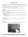
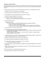
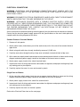
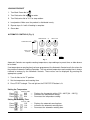
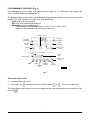
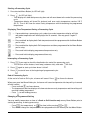
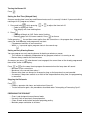
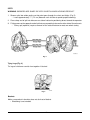
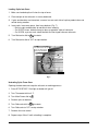
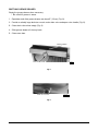
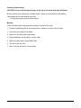
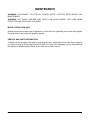
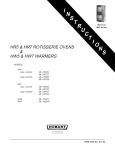
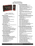
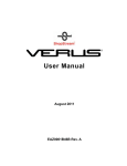
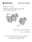
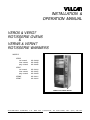
INSTALLATION &
OPERATION MANUAL
VERO5 & VERO7
ROTISSERIE OVENS
&
VERW5 & VERW7
ROTISSERIE WARMERS
MODELS
VERO5
std. controls
auto. controls
prog. controls
ML-126209
ML-126450
ML-126452
VERO7
std. controls
auto. controls
prog. controls
ML-126210
ML-126451
ML-126453
VERW5
VERW7
ML-126211
ML-126212
VERO5 Oven/VERW5 Warmer
VULCAN-HART
COMPANY,
FORM 31064 Rev. A (10-98)
P.O. BOX 696, LOUISVILLE, KY 40201-0696, TEL. (502) 778-2791
–1–
TABLE OF CONTENTS
GENERAL. . . . . . . . . . . . . . . . . . . . . . . . . . . . . . . . . . . . . . . . . . . . . . . . . . . . . . . . . . . . . . . . . . . . . . 4
INSTALLATION . . . . . . . . . . . . . . . . . . . . . . . . . . . . . . . . . . . . . . . . . . . . . . . . . . . . . . . . . . . . . . . . . 5
Location . . . . . . . . . . . . . . . . . . . . . . . . . . . . . . . . . . . . . . . . . . . . . . . . . . . . . . . . . . . . . . . . . . . 5
Legs / Casters . . . . . . . . . . . . . . . . . . . . . . . . . . . . . . . . . . . . . . . . . . . . . . . . . . . . . . . . . . . . . . 5
Assembly . . . . . . . . . . . . . . . . . . . . . . . . . . . . . . . . . . . . . . . . . . . . . . . . . . . . . . . . . . . . . . . . . . 5
Electrical Connections . . . . . . . . . . . . . . . . . . . . . . . . . . . . . . . . . . . . . . . . . . . . . . . . . . . . . . . 7
Before First Use . . . . . . . . . . . . . . . . . . . . . . . . . . . . . . . . . . . . . . . . . . . . . . . . . . . . . . . . . . . . 8
OPERATION . . . . . . . . . . . . . . . . . . . . . . . . . . . . . . . . . . . . . . . . . . . . . . . . . . . . . . . . . . . . . . . . . . . 9
Oven Control Panel . . . . . . . . . . . . . . . . . . . . . . . . . . . . . . . . . . . . . . . . . . . . . . . . . . . . . . . . . . 9
Manual Controls . . . . . . . . . . . . . . . . . . . . . . . . . . . . . . . . . . . . . . . . . . . . . . . . . . . . . . . . . . . . 9
Loading Product . . . . . . . . . . . . . . . . . . . . . . . . . . . . . . . . . . . . . . . . . . . . . . . . . . . . . . . . . . . 10
Automatic Controls . . . . . . . . . . . . . . . . . . . . . . . . . . . . . . . . . . . . . . . . . . . . . . . . . . . . . . . . . 10
Programmable Controls . . . . . . . . . . . . . . . . . . . . . . . . . . . . . . . . . . . . . . . . . . . . . . . . . . . . . 13
Preparing the Product . . . . . . . . . . . . . . . . . . . . . . . . . . . . . . . . . . . . . . . . . . . . . . . . . . . . . . . 16
Spits . . . . . . . . . . . . . . . . . . . . . . . . . . . . . . . . . . . . . . . . . . . . . . . . . . . . . . . . . . . . . . . . . . . . . 17
Suggested Roasting Guidelines . . . . . . . . . . . . . . . . . . . . . . . . . . . . . . . . . . . . . . . . . . . . . . . 19
Emptying Grease Drawer . . . . . . . . . . . . . . . . . . . . . . . . . . . . . . . . . . . . . . . . . . . . . . . . . . . . 20
Warmer Controls . . . . . . . . . . . . . . . . . . . . . . . . . . . . . . . . . . . . . . . . . . . . . . . . . . . . . . . . . . . 21
Using Warmers (Models VERW5 and VERW7) . . . . . . . . . . . . . . . . . . . . . . . . . . . . . . . . . . 21
Cleaning . . . . . . . . . . . . . . . . . . . . . . . . . . . . . . . . . . . . . . . . . . . . . . . . . . . . . . . . . . . . . . . . . . 22
MAINTENANCE . . . . . . . . . . . . . . . . . . . . . . . . . . . . . . . . . . . . . . . . . . . . . . . . . . . . . . . . . . . . . . . . 24
Model VERO5 Oven Only . . . . . . . . . . . . . . . . . . . . . . . . . . . . . . . . . . . . . . . . . . . . . . . . . . . . 24
Service and Parts Information . . . . . . . . . . . . . . . . . . . . . . . . . . . . . . . . . . . . . . . . . . . . . . . . 24
© VULCAN-HART COMPANY, 1998
–2–
Model VERO5 Oven
Model VERO7 Oven
Model VERW5 Warmer
Model VERW7 Warmer
Model VERO5 Oven/VERW5 Warmer
Model VERO7 Oven/VERW7 Warmer
–3–
Installation, Operation and Care of
VERO & VERW SERIES ROTISSERIE
OVENS AND WARMERS
PLEASE KEEP THIS MANUAL FOR FUTURE USE
GENERAL
The Vulcan-Hart VERO and VERW Series Rotisserie Ovens and Warmers feature stainless steel
interior and exterior for ease of cleaning. The grease drawer has a drain valve for elimination of excess
fat and can be completely removed for cleaning.
Rotating, self-basting spits or flat baking racks and combination convection and radiant heat provide
thorough cooking and even browning. Hot spots are also eliminated.
Oven controls provide "Manual/Time Controlled" operation, "Automatic/Electronic Timer Control"
operation, or "Programmable Control" operation.
Full view tempered glass doors, both front and back, and quartz lighting promote visual appeal and
stimulate customer interest.
The VERW warming cabinet features low velocity, high humidity air circulation which keeps foods
moist. The warming cabinet has three shelves.
Ovens and warming cabinets come in two sizes. Stacking kits are available to stack ovens and warming
cabinets.
VERO5 — Oven with five spits (15-20 chickens).
VERO7 — Large oven with seven spits (30-35 chickens).
VERW5 — Warming cabinet.
VERW7 — Warming cabinet.
Features and Options
Quantity Required per Oven*
Spit
Basket
Turkey Spit
Baking Plate
Chicken Rack
Warmer Shelves
VERO5
5 std.
5 opt.
1 opt.
5 opt.
5 opt.
NA
VERO7
7 std.
7 opt.
1 opt.
NA
7 opt.
NA.
VERW5
NA
NA
NA
NA
NA
3 std.
VERW7
NA
NA
NA
NA
NA
3 std.
* Rotisserie inserts can be intermixed requiring less than the maximum shown in the chart.
–4–
INSTALLATION
Immediately after unpacking the oven, check for possible shipping damage. If oven is found to be
damaged after unpacking, save the packaging material and contact the carrier within 15 days of
delivery.
Prior to installation, test the electrical service to assure that it agrees with the specifications on the
machine data plate located on the right side panel near the controls.
The ovens and warmers are secured to the skid with four screws which must be removed.
LOCATION
WARNING: THE OVEN SHOULD NOT BE ACCESSIBLE TO THE CUSTOMER. HOT GLASS AND
PARTS CAN CAUSE BURNS.
The oven may be placed where cooking may be observed to enhance customer awareness, but must
be installed on a level surface.
The installation location must allow adequate clearances for servicing and for proper operation of the
front and rear doors.
• A minimum wall clearance of 10" (254 mm) from any glass, and 4" (101.6 mm) from each side
panel must be maintained.
LEGS / CASTERS
Each oven and warmer is furnished on 19/16" (39.7 mm) legs. Casters come with the stacking kit or can
be ordered as an accessory.
ASSEMBLY
Place the two bottom plates in oven. The two plates slant to the middle to allow fat to drip into the grease
drawer (Fig.1).
PL-41161
Model VERO5 & VERO7
Fig. 1
–5–
Assembling Stacked Devices
When stacking ovens or oven and warmer, the location of the controls on the top oven may be changed
to the bottom of the control panel. Contact your local Vulcan-Hart servicer to change the location of the
controls.
If stacking an oven and warmer, the normal location for the warmer is on the bottom of the stack.
1. Unpack ovens or oven and warmer, and stacking kit.
2. Remove all interior packed loose racks, rotor, pans, and spits.
3. Place bottom oven or warmer onto blocks at least 8" (20 cm) high.
4. Remove (4) legs provided on oven or warmer.
5. Assemble (4) casters supplied with stacking kit.
• Make sure (2) casters with brakes are mounted on the same side.
6. Remove blocks carefully.
Alternate lift method:
• The oven or warmer may be lifted through the grease pan opening with forks.
a. Open ALL doors and remove grease pan.
b. Run forks all of the way through the opening where the grease pan was located.
c. Make sure forks rest on the frame member and are spread as far apart as possible.
7. Position lower oven or warmer onto the floor.
8. Remove partial top cover from the lower oven or warmer.
• The partial cover will not be reinstalled but must be saved for future use if ovens or oven and
warmer are ever unstacked.
• DO NOT DISCARD THE PARTIAL TOP COVER, KEEP IT WHERE IT CAN BE FOUND
WHEN NEEDED IN THE FUTURE.
9. Remove (2) top corner screws on non-control panel side of bottom oven or warmer. Screws will be
replaced with longer screws later in stacking procedure.
10. Remove all side panels from each oven or oven and warmer.
11. Carefully place top oven onto blocks and remove the (4) legs.
12. Carefully position upper oven onto top of lower oven or warmer.
• See above for alternate lift method.
13. Align and assemble through control panel side (2) M8 x .625" long bolts from bottom oven or warmer
to top oven.
14. Align and assemble through non-control panel side (2) M5 x .625" long bolts from top oven to
bottom oven or warmer.
15. Slide flat protector tray into drawer opening of top oven.
16. Assemble in place with (2) M5 x .625" long screws.
–6–
ELECTRICAL CONNECTIONS
WARNING: ELECTRICAL AND GROUNDING CONNECTIONS MUST COMPLY WITH THE
APPLICABLE PORTIONS OF THE NATIONAL ELECTRICAL CODE AND/OR OTHER LOCAL
ELECTRICAL CODES.
WARNING: DISCONNECT ELECTRICAL POWER SUPPLY AND PLACE A TAG AT THE DISCONNECT
SWITCH INDICATING THAT YOU ARE WORKING ON THE CIRCUIT.
WARNING: APPLIANCES EQUIPPED WITH A FLEXIBLE ELECTRIC SUPPLY CORD ARE
PROVIDED WITH A THREE-PRONG GROUNDING PLUG. THIS PLUG MUST BE CONNECTED
INTO A PROPERLY GROUNDED THREE-PRONG RECEPTACLE. IF THE RECEPTACLE IS NOT
THE PROPER GROUNDING TYPE, CONTACT AN ELECTRICIAN. DO NOT REMOVE THE
GROUNDING PRONG FROM THIS PLUG.
Access the electrical connection point by removing panel(s) on the side where the controls are located.
Ensure that the electrical power supply agrees with the specifications on the oven's data plate and
complies with the wiring diagram on the oven.
Stacked Ovens or Oven and Warmer
1. Remove all side panels.
2. Attach power leads (furnished as part of the stacked set) to the line side of the terminal block of
upper oven.
3. Attach wire guide with wires already installed by means of (2) M5 nuts.
4. Carefully route wires through bushing in top oven and attach to terminal block of top oven.
5. At the same time attach power leads to lower oven or warmer terminal block as shown on the wiring
diagram and attach power supply conduit to the bottom of the lower oven or warmer.
6. Attach power supply leads to line side of terminal block.
7. Inspect and check all wiring and terminal connections for tightness and proper routing away from
any moving parts or pinch points.
8. Carefully replace the ovens' or oven and warmer's panels.
Single Oven or Warmer
1. At the same time attach power leads to oven or warmer terminal block as shown on the wiring
diagram and attach power supply conduit to the bottom of the oven or warmer.
2. Attach power supply leads to line side of the terminal block.
3. Inspect and check all wiring and terminal connections for tightness and proper routing away from
any moving parts or pinch points.
4. Carefully replace the oven's or warmer's panels.
Refer to the Electrical Data chart on the next page.
–7–
ELECTRICAL DATA
MODEL
VOLTS
HERTZ
PHASE
CIRCUIT SIZE*
(AMPS)
VERO5
208
208
240
240
60
60
60
60
1
3
1
3
35
20
35
20
VERO7
208
208
240
240
60
60
60
60
1
3
1
3
60
35
60
35
VERW5
208
208
240
240
60
60
60
60
1
3
1
3
15
10
15
10
VERW7
208
208
240
240
60
60
60
60
1
3
1
3
15
10
15
10
(2) VERO5
208
208
240
240
60
60
60
60
1
3
1
3
70
40
70
40
(2) VERO7
208
240
60
60
3
3
70
70
VERO5 & VERW5
208
208
240
240
60
60
60
60
1
3
1
3
50
30
50
30
VERO7 & VERW7
208
240
60
60
3
3
50
45
STACKED MODELS
* Maximum Circuit Breaker Size / Minimum Circuit Amperage compiled in accordance with the
National Electrical Code, 1990 edition.
BEFORE FIRST USE
WARNING: DISCONNECT ELECTRICAL POWER BEFORE CLEANING.
1. Oven must be "burned in" to release any odors that might result from heating the new surfaces in
oven.
2. Clean oven, accessories, and warmer (if present), both inside and outside, with warm soapy water.
3. Rinse thoroughly and wipe dry with a soft clean cloth.
• Avoid water contact with quartz lamps.
4. Operate oven at maximum temperature setting of 480°F (249°C) for 45 minutes.
• Smoke with an unpleasant odor will normally be given off during this burn-in period.
–8–
OPERATION
WARNING: HOT GLASS, GREASE, AND PARTS CAN CAUSE BURNS. USE CARE WHEN
OPERATING AND SERVICING THE OVEN.
OVEN CONTROL PANEL (Fig. 2)
DISPLAY — Shows temperature (°F) and time (HH:MM)
when first turned on.
DISPLAY
Programmable/Automatic: Colon flashing, remaining
cooking time is shown.
Manual: Nothing will show on the display.
PROGRAMMABLE
CONTROLS
AUTOMATIC CONTROLS — Set all dials on "P". See
pages 10-12 in this manual.
PROGRAMMABLE CONTROLS – Set all dials on "P". See
pages 13-16 in this manual.
THERMOSTAT
DIAL
MANUAL CONTROLS – Use control dials. Comes with
Programmable Controls only.
Thermostat Dial — 0°F means heat is OFF.
• Turn dial to desired temperature (150-480°F
[66°C - 249°C]).
ROTISSERIE
DIAL
Rotisserie Dial
— "0/P" means rotisserie is OFF.
• Set Dial Thermostat to desired temperature.
• Set the Rotisserie on:
- Oven working without restrictions.
- Only rotor moves.
MAIN POWER
DIAL
- Oven working, one lamp remains off.
- Oven working, both lamps remain off.
PL-41175-1
Fig. 2
• Set the Main Power dial on the hand symbol.
Operator side heating lamp will remain on until
the desired temperature is reached in oven.
Main Power Dial — "0" means OFF.
• Set Main Power dial on the hand symbol.
• Set Rotisserie dial to desired manual setting.
• Set Thermostat Dial to desired temperature.
–9–
LOADING PRODUCT
1. Turn Main Power dial to
.
2. Turn Rotisserie dial to
to rotate.
3. Turn Rotisserie dial to "0/P" to stop rotation.
4. Load product. Make sure the product is distributed evenly.
5. Repeat steps 2-4 until all loading is complete.
6. Close door.
AUTOMATIC CONTROLS (Fig. 3)
TEMPERATURE
UP
TIME OF DAY
POWER INDICATOR
START / STOP
BUTTON
ROASTING TIME DOWN
BUZZER
PL-41184-1
Fig. 3
Automatic Controls can regulate roasting temperature, stop cooking at a preset time, or allow buzzer
to be timed.
If no temperature or roasting time has been programmed, the Automatic Control recalls the values for
the previous Automatic Cooking Operation. The last entered temperature and roasting time is always
retained in memory by the Automatic Controls. These values can be displayed by pressing the
appropriate symbol.
1. Turn all dials to the "P" position.
2. Set the temperature and roasting time.
3. Press START to begin. The red light on the START/STOP button is lit.
Setting the Temperature
DISPLAY TEMP
Press
Press
Press
+
+
325
326
324
—
—
—
Displays the thermostat setting (150 - 480°F [66 - 249°C]).
Increases the temperature setting.
Decreases the temperature setting.
—
—
—
Displays the automatic roasting time.
Increases the automatic roasting time.
Decreases the automatic roasting time.
Setting the Roasting Time
DISPLAY TIME
Press
Press
Press
+
+
1:15
1:16
1:14
– 10 –
Setting an Early Warning Buzzer
Assume roasting time is one hour and fifteen minutes and it is currently 2 o’clock. The cycle completes
and the buzzer will sound at 3:15. If you want an early warning buzzer for basting or whatever reason,
program as follows:
DISPLAY TIME
Press
Press
+
Press START.
3:15
3:00
— Displays the sum of the current time plus the roasting time.
— Buzzer will sound at 3:00.
— Roasting begins.
• At 3:00, interim buzzer sounds. Press
to silence.
• At 3:15, roasting stops and buzzer sounds again. Press
to silence.
Setting End Time (Delayed Start)
Assume roasting time is one hour and fifteen minutes and it is currently 2 o’clock. If you want to finish
roasting at 4:00, program the Automatic Control as follows:
DISPLAY TIME
Press
Press
+
Press START.
3:15
4:00
—
—
—
Displays sum of current time plus roasting time.
Roasting will stop at 4:00.
Red light on the START/STOP button is lit.
Rotisserie stays off until:
• Roasting begins at 2:45. Colon flashes.
• Roasting stops at 4:00; buzzer sounds. Press
to silence.
Interrupting an Automatic Cooking Operation
If you want to temporarily interrupt an Automatic Cooking Operation, press START/STOP.
• Red light on the START/STOP button flashes.
• Colon stops flashing.
• Rotisserie stops.
• Heat lamps and elements go off.
• Automatic Control retains the set temperature and the remaining roasting time.
• Current temperature and remaining roasting time are displayed.
• Temperature decreases because heating is off. The control does not compensate.
To restart, press START/STOP again. The Automatic Cooking Operation will resume.
Stopping an Automatic Cooking Operation
When an Automatic Cooking Operation is completed, a buzzer sounds.
If you want to temporarily interrupt an Automatic Cooking Operation, see above.
If you want to abort an Automatic Cooking Operation, turn Main Power dial to "0".
• Temperature and Roasting Time remains in memory, not the remaining cooking time.
Changing A Setting
All settings, except Time of Day, can be changed before, during, or after the cooking process. Time of
Day cannot be changed during an Automatic Cooking Operation. After a change, operation continues
according to new values.
– 11 –
Stopping the Rotisserie
Turn Main Power dial to "0" or press START/STOP.
• Everything will switch off.
Setting the Time of Day
Time of Day cannot be reset during an Automatic Cooking Operation.
• Red light on the Start/Stop button must be off.
• Colon is not flashing.
Set the Time of Day as follows:
DISPLAY TIME
Press
Press
+
+
9:23
9:24
9:22
—
—
—
Current time of day is displayed.
Increases the time of day.
Decreases the time of day.
Turning the Buzzer OFF
Press
.
Resetting the Automatic Control
Press STOP/START.
• Automatic Control retains Time and Temperature for the last Automatic Cooking Operation.
• Remaining cooking time and early warning buzzer are lost.
Operating in Fahrenheit or Celsius Degrees
Rotisserie dial must be on "0/P".
To operate oven with Fahrenheit degrees, press
while turning Main Power dial from "0" to "P".
• Fahrenheit lamp will be lit.
• Oven will continue to operate in Fahrenheit degrees.
To operate in Celsius, press
while turning Main Power dial from "0" to "P".
• Oven will continue to operate in Celsius degrees.
– 12 –
PROGRAMMABLE CONTROLS (Fig. 4)
All programming must be done with Thermostat dial (top) on "P", Rotisseries dial (middle) on
"0/P", and Main Power dial (bottom) on "P".
The programmable control allows you to program three different functions for each of the 5 menu
buttons. The three functions are Cook, Grill, and Warm/Hold.
• Cook cycle is for slow roasting.
• Grill cycle is for searing and browning.
• Warm/Hold cycle is a holding cycle.
- Recommended holding temperature is 160°F (71°C) or 180°F (82°C).
- Rotisserie will continue to turn during the hold cycle.
PROBE
ROTOR
PROGRAM
INDICATORS
PROCESS
INDICATORS
PROGRAM
KEYS
POWER
INDICATOR
START / STOP
BUTTON
BUZZER
UP
TIME OF
DAY
TEMPERATURE
WARM / HOLD
PROCESS
TIME
DOWN
COOKING
PROCESS
GRILL
PROCESS
PROGRAM
END
PL-41185-1
Fig. 4
Setting the Time of Day
1. Turn Main Power dial to "P".
2. Press and hold
and adjust to current time by using
or
. This is a 12-hour clock.
The actual time of day may be viewed on the display at any time, except during a running process, by
pressing
.
– 13 –
Programming Menu Buttons
1. Before entering the program mode, you must first press a Menu Button. Press Menu Button #1. Its
LED will light.
2. To enter Program mode, press and hold both
and
simultaneously until time display shows
"PROG" (approximately 2 seconds). The LED on Menu Button #1 and Cooking Process Indicator
will start blinking.
3. Cook function time and temperature will be programmed first.
Press and hold
while pressing
or
to adjust to temperature desired.
• Maximum allowable temperature setting is 480°F (249°C); minimum is 32°F (0°).
Press and hold
while pressing
or
to adjust to time desired.
• Maximum time setting is 5 hours, 59 minutes.
4. Program the Grill function for Menu Button #1.
Press
. The Grilling Process Indicator and LED on Menu Button #1 will start blinking.
Press and hold
while pressing
or
to adjust to temperature desired.
• Maximum allowable temperature setting is 480°F (249°C); minimum is 32°F (0°C).
Press and hold
while pressing
or
to adjust to time desired.
5. Program the Warm/Hold function for Menu Button #1.
Press
. The Warm/Hold Process Indicator and LED on Menu Button #1 will start blinking.
Press and hold
while pressing
or
to set temperature for the hold cycle.
You cannot program a time for the warm/hold function. If you try to program a time, the buzzer will
sound for 3 seconds, then shut off. After programming of Menu Button #1 is completed, the time
display will show the current time of day.
6. Press flashing Menu Button #1 to lock in the programmed settings.
After programming, the display will show the time and temperature programmed for the Cook
function. If you have programmed "0" time and minimum temperature (32°F [0°C]) for the Cook
function, the displays will show the actual cavity temperature and actual time of day.
7. Continue programming Menu Buttons 2-5 in the same manner.
Verifying Programmed Temperatures and Times
Cook function: Press and hold the desired Menu Button, then press
.
.
Grill function: Press and hold the desired Menu Button, then press
Warm/Hold : Press and hold the desired Menu Button, then press
.
• Only the temperature will be displayed in the Warm/Hold function.
• Time display will show "00:00".
– 14 –
Starting a Processing Cycle
1. Press desired Menu Button (its LED will light).
2. Press
(its LED will light).
• Time display will show total processing time and will count down to the end of the processing
cycle.
• Temperature display will show Pht (preheat) until oven cavity temperature reaches 125°F
(52°C). Then it will show the actual cavity temperature while maintaining the programmed
temperature.
Displaying Time/Temperature During a Processing Cycle
— If pressed during a processing cycle, probe icon under temperature display will light
and probe temperature will be displayed for 20 seconds. You may press it again if
you like.
— Press and hold to display both Cook temperature and time programmed for the Menu Button
you're using.
— Press and hold to display both Grill temperature and time programmed for the Menu Button
you're using.
— Press and hold to display programmed temperature only.
— Press and hold to display programmed time only.
Interrupting a Processing Cycle
1. Press
if you want to check the food before the end of the processing cycle.
• This will turn off the heaters, front lamp (customer side), and rotor.
will flash.
2. Press
again to start cycle from where it left off.
3. Press
to start all over at the beginning of programmed cycle.
End of Processing Cycle
At the end of a Cook or Grill cycle, a buzzer will sound. Press
to silence the buzzer.
When oven goes into Warm/Hold cycle, the buzzer will sound and operator side lamp will cycle on and
off with heaters.
• Press and hold
to silence buzzer.
• The temperature and time displays will show actual oven cavity temperature and time of day until
reaching holding temperature.
• Press
to end holding process.
Changing a Programmed Setting
You may modify temperature or time of a Cook or Grill function only on any Menu Button prior to
starting processing, or during processing.
• Press
(for temperature) or
(for time) while pressing
or
.
• This will not change the temperature or time programmed in the memory for that Menu Button.
– 15 –
Turning the Buzzer Off
Press
.
Setting the End Time (Delayed Start)
Assume roasting time is one hour and fifteen minutes and it is currently 2 o'clock. If you want to finish
roasting at 4:00, program as follows:
1. Press and hold
while pressing
or
• Colon in display will flash.
• Time display will show cooking time.
to adjust the time to 4:00.
2. Press
.
• Cooking will begin at 2:45. Colon starts flashing.
• Roasting stops at 4:00; buzzer sounds. Press
to silence.
If after pressing
the end time comes earlier than the current time + the program time, a beep will
sound (for three minutes) and program will not start.
• Programmed end time is now cancelled.
• When
is pressed again, program starts in the normal way.
Setting an Early Warning Buzzer
You can program an early warning buzzer for basting or whatever reason.
• This function is completely independent of any program, whether it is running or not.
• Buzzer always sounds for three minutes.
As soon as you press
when buzzer is not engaged, the current time or the already programmed
time will be shown in the display.
Press
or
at the same time to program the moment when the beep tone will sound.
• Minimum is the current time.
• Maximum is the current time minus 1.
• Buzzer delay time can always be changed as long as the beep tone has not sounded.
• As soon as a beep tone sounds as a result of the elapsed buzzer delay time, the programming
is cancelled.
Stopping the Rotisserie
Press
.
• Heaters, operator side lamp, and rotisserie will turn off.
• To start rotisserie again, see procedures described under "Interrupting a Processing Cycle".
PREPARING THE PRODUCT
•
•
•
•
Oven is not designed to roast frozen foods.
Use only fresh or previously thawed product.
Clean all work areas before and after preparing poultry.
Maintain proper sanitation at all times.
– 16 –
SPITS
WARNING: SKEWERS ARE SHARP. BE VERY CAREFUL WHEN LOADING PRODUCT.
1. Skewer spits into whole poultry so that point goes through the chest and thighs (Fig. 5).
• Leave approximately 1⁄2" (1.2 cm) between each chicken to permit proper browning.
2. Place sharp end of spit into holes on one side of rotisserie positioning breast toward the operator.
3. Fit the groove on the opposite end of spit into corresponding holes on the other side of the rotisserie.
• Turkey spit (optional) requires removal of the rotisserie drum to roast one whole turkey.
Fig. 5
Tying Legs (Fig. 6)
Tie legs of chicken or cornish hen together if desired.
Fig. 6
Baskets
Make sure product in baskets does not stick out of basket.
• Shortening is not needed.
– 17 –
Loading Spits Into Oven
1. Make sure loaded spits will clear the top of oven.
2. Place weight so the rotisserie is evenly balanced.
3. If spits and baskets are intermixed, use one less on each side of spit so product does not
collide during rotation.
4. Insert spits, leave one space, then hang baskets (Fig. 7).
• Be sure spits and baskets do not touch when rotating.
• On VERO7 ovens, baskets hang on pins on opposite sides of rotisserie.
• On VERO5, a pin on each side of basket fits into ringed holes on rotisserie.
5. Turn Rotisserie dial to
to rotate.
6. Turn Rotisserie dial to "0/P" to stop rotation.
Oven With Baskets and Spits
Leave One Empty Space
Between Spit and Basket
Holes for Spit
Basket
Spit
Pins
PL-41160-1
Fig. 7
Unloading Spits From Oven
Opening the door does not stop the rotisserie or cooking process.
1. Press STOP/START. Red light on button will go off.
2. Turn Thermostat dial to 0°F.
3. Turn Main Power dial to
.
4. Remove spits or baskets.
5. Turn Rotisserie dial to
to rotate.
6. Turn Rotisserie to "0/P" to stop rotation.
7. Remove the next utensil.
8. Repeat steps 3 thru 5 until unloading is complete.
– 18 –
SUGGESTED ROASTING GUIDELINES
The chart indicates suggested cooking times and temperatures. Initial product temperature, size,
shape, and other factors may require adjustment to suit your operation.
Product
Thermostat
(°F)
(°C)
Time
(HH:MM)
Internal
Temperature
(°F)
(°C)
Capacity
VERO5
VERO7
Chicken, Whole,
3 lb. (1.4 kg)
350-275
177-135
1:10 - 1:30
180-185
82-85
15-20
28-35
Cornish Hens,
1 lb. (.45 kg)
350-275
177-135
0:50 - 1:20
180-185
82-85
20-24
28-42
Duck, Whole,
4-41⁄2 lb. (1.8-2 kg)
350-275
177-135
1:50 - 2:15
180-185
82-85
10
14
Turkey, Whole,
11-13 lb. (5-5.9 kg)
350-275
177-135
1:50 - 2:15
180-185
82-85
1
1
Roast Beef,
4 lb. (1.8 kg)
350-275
177-135
0:45 - 0:55
140 Rare
160 Medium
180 Well Done
60
71
82
10
14
Pork Ribs,
3 lb. (1.4 kg)
350
177
0:50 - 1:20
170
77
5
7
*These are approximate cooking times. They will fluctuate based upon the weight and size of the
product.
– 19 –
EMPTYING GREASE DRAWER
Empty the grease drawer when necessary.
• Be careful if grease is warm.
1. Open door and slide grease drawer out about 5" (13 cm) (Fig. 8).
2. Provide a suitably large bucket or vessel under drain valve and open valve handle (Fig. 8).
3. Close drain valve when empty (Fig. 9).
4. Slide grease drawer all the way back.
5. Close oven door.
GREASE DRAWER
DRAIN VALVE OPENED
PL-41169-1
Fig. 8
DRAIN VALVE CLOSED
Fig. 9
– 20 –
PL-41168-1
WARMER CONTROLS (Fig. 10)
Fig. 10
Thermometer
—
Displays temperature in degrees Fahrenheit.
Thermostat
—
0°F is OFF. Turn dial to desired temperature.
USING WARMERS (Models VERW5 and VERW7)
Fill warmer drawer with cold water about three-quarters full to minimize steaming.
• Use softened water, if available, to reduce lime build-up in drawer.
Cooked product other than poultry may be held in the warmer for 3 to 4 hours; then it must be
refrigerated.
When holding poultry, it is recommended that the temperature of the warmer be at least 160°F – 180°F
(71°C - 82°C) and that poultry be held no longer than 2 hours.
Every 4 to 5 hours, add lukewarm water to drawer as needed.
• If water evaporates completely, product will dry out.
– 21 –
CLEANING
WARNING: DISCONNECT ELECTRICAL POWER BEFORE CLEANING.
Allow oven to cool before cleaning.
CAUTION: Do not use oven cleaners. Do not clean with a high pressure hose.
1. Wash both doors and inside glass with warm soapy water, rinse and dry or use a commercial glass
cleaner.
2. With door open, pull inside glass away from door to clean.
• Take extra care when cleaning outside surface of inner glass door because of its special
reflective coating.
• Do not remove glass from door.
3. Clean control panel with a damp cloth only.
4. Remove oven rotisserie, spits, bottom plates, and other removable parts and wash in a sink with
warm soapy water.
5. Rinse parts thoroughly and dry with a soft clean cloth.
6. Clean oven interior and exterior with warm soapy water.
7. Rinse interior and exterior thoroughly and dry with a soft clean cloth.
Cleaning Grease Drawer
1. Empty grease drawer (see page 20).
2. Remove drawer when machine is idle.
3. Wash in a sink with warm soapy water.
• Any hard soil can be scrubbed with a soft, non-scratching pad.
4. Rinse and wipe dry with a soft clean cloth.
5. Return clean drawer to oven bottom.
Cleaning Warmers
1. Remove water drawer and shelves.
2. Wash with warm soapy water, rinse and dry.
3. If scale builds up on water drawer or warmer interior, soak with vinegar.
4. Rinse thoroughly and dry with a soft clean cloth.
– 22 –
Cleaning Quartz Lamps
CAUTION: Do not clean the quartz lamps in the top of the oven with soap and water.
Be very careful when cleaning or handling lamps. Lamps can be broken by mishandling.
Clean lamps with a cloth soaked in alcohol.
• Do not touch lamps with your bare hands.
Monthly
Clean ventilation grate and fan blades located in the top of the oven.
1. Remove ventilation grate by unscrewing nuts (clockwise) on both sides of vents.
2. Unscrew nut in center of fan blade.
3. Wash in a sink with warm soapy water.
4. Rinse thoroughly and dry with a soft dry cloth.
5. Wipe fan blades with a clean damp cloth.
6. Dry with a soft dry cloth.
7. After cleaning, reinstall in reverse order.
– 23 –
MAINTENANCE
WARNING: DISCONNECT ELECTRICAL POWER SUPPLY BEFORE PERFORMING ANY
MAINTENANCE.
WARNING: HOT GLASS, GREASE, AND PARTS CAN CAUSE BURNS. USE CARE WHEN
OPERATING AND SERVICING THE OVEN.
MODEL VERO5 OVEN ONLY
Should the rotisserie become out of alignment, use the allen key (provided) to unscrew and retighten
the drum on the rotor shaft until properly aligned.
SERVICE AND PARTS INFORMATION
To obtain service and parts information concerning this oven, contact the Vulcan-Hart Service Agency
in your area (refer to listing supplied with the oven), or Vulcan-Hart Company Service Department at
the address or phone number shown on the front cover of this manual.
FORM 31064 Rev. A (10-98)
– 24 –
PRINTED IN U.S.A.