1
User Manual August 2011 EAZ0061B46B Rev. A Trademarks Snap-on, Fast-Track, Scanner, ShopStream, and VERUS are trademarks of Snap-on Incorporated. All other marks are trademarks or registered trademarks of their respective holders. Copyright Information ©2011 Snap-on Incorporated. All rights reserved. Disclaimer of Warranties and Limitation of Liabilities The information, specifications and illustrations in this manual are based on the latest information available at the time of printing. While the authors have taken due care in the preparation of this manual, nothing contained herein: • Modifies or alters in any way the standard terms and conditions of the purchase, lease, or rental agreement under the terms of which the equipment to which this manual relates was acquired. • Increases in any way the liability to the customer or to third parties. Snap-on reserves the right to make changes at any time without notice. IMPORTANT: Before operating or maintaining this unit, please read this manual carefully paying extra attention to the safety warnings and precautions. Visit our websites at: http://diagnostics.snapon.com (North America) www1.snapon.com/diagnostics/uk (United Kingdom) snapontools.com.au (Australia and New Zealand) For Technical Assistance Call 1-800-424-7226 (North America) CALL +44 (0) 845 601 4736 (United Kingdom) 1800 810 581 (Australia and New Zealand) E-mail [email protected] (United Kingdom) For technical assistance in all other markets, contact your selling agent. ii Safety Information For your own safety and the safety of others, and to prevent damage to the equipment and vehicles upon which it is used, it is important that the accompanying Important Safety Instructions be read and understood by all persons operating, or coming into contact with, the equipment. We suggest you store a copy near the unit in sight of the operator. This product is intended for use by properly trained and skilled professional automotive technicians. The safety messages presented throughout this manual are reminders to the operator to exercise extreme care when using this test instrument. There are many variations in procedures, techniques, tools, and parts for servicing vehicles, as well as in the skill of the individual doing the work. Because of the vast number of test applications and variations in the products that can be tested with this instrument, we cannot possibly anticipate or provide advice or safety messages to cover every situation. It is the automotive technician’s responsibility to be knowledgeable of the system being tested. It is essential to use proper service methods and test procedures. It is important to perform tests in an appropriate and acceptable manner that does not endanger your safety, the safety of others in the work area, the equipment being used, or the vehicle being tested. It is assumed that the operator has a thorough understanding of vehicle systems before using this product. Understanding of these system principles and operating theories is necessary for competent, safe and accurate use of this instrument. Before using the equipment, always refer to and follow the safety messages and applicable test procedures provided by the manufacturer of the vehicle or equipment being tested. Use the equipment only as described in this manual. Read, understand and follow all safety messages and instructions in this manual, the accompanying safety manual, and on the test equipment. Safety Message Conventions Safety messages are provided to help prevent personal injury and equipment damage. All safety messages are introduced by a signal word indicating the hazard level. ! DANGER Indicates an imminently hazardous situation which, if not avoided, will result in death or serious injury to the operator or to bystanders. ! WARNING Indicates a potentially hazardous situation which, if not avoided, could result in death or serious injury to the operator or to bystanders. ! CAUTION Indicates a potentially hazardous situation which, if not avoided, may result in moderate or minor injury to the operator or to bystanders. iii Safety Information Important Safety Instructions Safety messages contain three different type styles. • Normal type states the hazard. • Bold type states how to avoid the hazard. • Italic type states the possible consequences of not avoiding the hazard. An icon, when present, gives a graphical description of the potential hazard. Example: ! WARNING Risk of unexpected vehicle movement. • Block drive wheels before performing a test with the engine running. A moving vehicle can cause injury. Important Safety Instructions For a complete list of safety messages, refer to the accompanying safety information. SAVE THESE INSTRUCTIONS iv Contents Safety Information ..................................................................................................................... iii Contents ...................................................................................................................................... v Chapter 1: Using This Manual ................................................................................................... 1 Conventions.................................................................................................................................. 1 Bold Text ................................................................................................................................ 1 Symbols ................................................................................................................................. 1 Terminology ........................................................................................................................... 1 Notes and Important Messages ............................................................................................. 2 Procedures............................................................................................................................. 2 Tool Help................................................................................................................................ 2 Chapter 2: Introduction.............................................................................................................. 3 EEMS325 Display Device............................................................................................................. 3 Functional Description ........................................................................................................... 3 Technical Specifications ........................................................................................................ 5 The Stand .............................................................................................................................. 7 Wrist Strap (Optional)............................................................................................................. 7 Control Buttons ...................................................................................................................... 7 LEDs ...................................................................................................................................... 8 Power Conservation............................................................................................................... 8 Power Sources....................................................................................................................... 8 SCAN Module............................................................................................................................. 10 Functional Description ......................................................................................................... 10 Technical Specifications ...................................................................................................... 11 Power Sources..................................................................................................................... 11 Chapter 3: Getting Started....................................................................................................... 12 Powering Up ............................................................................................................................... 12 Module Buttons .................................................................................................................... 13 VERUS Toolbar ................................................................................................................... 14 Windows Toolbar ................................................................................................................. 19 Powering Down .......................................................................................................................... 19 Emergency Shutdown .......................................................................................................... 19 Chapter 4: Scanner Operations............................................................................................... 20 Getting Started ........................................................................................................................... 20 The Demonstration Program................................................................................................ 20 Disconnecting the VERUS Unit From a Vehicle................................................................... 21 Vehicle Identification................................................................................................................... 22 Alternative Vehicle Identification .......................................................................................... 24 Connecting to a Vehicle.............................................................................................................. 25 Cables .................................................................................................................................. 25 No Communication Message ............................................................................................... 26 v Contents Navigation................................................................................................................................... 26 Scanner Screen Layout ....................................................................................................... 26 Screen Messages ................................................................................................................ 29 Making Selections ................................................................................................................ 30 Operations .................................................................................................................................. 30 Data Display......................................................................................................................... 31 Codes Menu......................................................................................................................... 36 Functional Tests................................................................................................................... 39 Generic Functions ................................................................................................................ 41 Troubleshooter ..................................................................................................................... 41 Scanner Toolbar Operations ................................................................................................ 42 Exiting the SCAN Module ........................................................................................................... 46 Downloading Firmware............................................................................................................... 47 Chapter 5: OBD Direct.............................................................................................................. 50 OBD Health Check ..................................................................................................................... 50 Global OBD II Code Check .................................................................................................. 51 Global OBD II Clear Codes .................................................................................................. 52 Readiness Monitors ............................................................................................................. 52 Connector Information ......................................................................................................... 53 OBD Diagnose............................................................................................................................ 53 Start Communication ........................................................................................................... 53 Select Communication Protocol ........................................................................................... 57 Connector Information ......................................................................................................... 57 Chapter 6: Component Test .................................................................................................... 58 Vehicle Identification................................................................................................................... 58 Creating a Favorites List ...................................................................................................... 58 Identifying a Test Vehicle ..................................................................................................... 60 Operations .................................................................................................................................. 62 Component Information ....................................................................................................... 62 Tests .................................................................................................................................... 63 VERUS Toolbar Menu Options ............................................................................................ 67 Chapter 7: Scope Multimeter................................................................................................... 68 Getting Started ........................................................................................................................... 68 Capabilities .......................................................................................................................... 68 Leads, Probes and Adapters ............................................................................................... 70 Navigation................................................................................................................................... 73 Screen Layout ...................................................................................................................... 73 Making Selections ................................................................................................................ 76 Operations .................................................................................................................................. 77 Starting the Scope and Multimeter....................................................................................... 77 Scope and Multimeter Setup................................................................................................ 79 Chapter 8: Information ............................................................................................................. 92 North America............................................................................................................................. 92 United Kingdom and Australia .................................................................................................... 92 Vehicle Identification ............................................................................................................ 92 Diagnostic Trouble Codes.................................................................................................... 94 Engine Management Component Testing............................................................................ 95 vi Contents Engine Management Pin Data ............................................................................................. 99 Component Locations ........................................................................................................ 100 Wiring Diagrams................................................................................................................. 102 Chapter 9: Help Operations ................................................................................................... 104 Using the Help Toolbar............................................................................................................. 104 Chapter 10: System Settings Operations............................................................................. 105 Wireless Communication.......................................................................................................... 105 Pairing the Wireless SCAN Module ................................................................................... 106 Chapter 11: Data Manager ..................................................................................................... 108 Screen Layout .......................................................................................................................... 108 My Data.............................................................................................................................. 109 Open .................................................................................................................................. 109 New .................................................................................................................................... 110 Delete................................................................................................................................. 111 Rename ............................................................................................................................. 112 Properties........................................................................................................................... 112 More ................................................................................................................................... 112 Chapter 12: Vehicle History Operations............................................................................... 113 Screen Layout .......................................................................................................................... 113 Vehicle History Main Body ................................................................................................. 114 Vehicle History Toolbar ...................................................................................................... 114 Shop Information ...................................................................................................................... 118 Chapter 13: Maintenance ....................................................................................................... 119 Cleaning the Touch Screen ...................................................................................................... 119 Calibrating the Touch Screen ................................................................................................... 119 Cleaning and Inspecting the Unit.............................................................................................. 120 Fan Filter Service ..................................................................................................................... 120 Battery Pack Service ................................................................................................................ 121 Battery Pack Safety Guidelines ......................................................................................... 121 Replacing the Battery Pack................................................................................................ 122 Disposing of the Battery Pack ............................................................................................ 122 Battery Pack Calibration .................................................................................................... 123 VERUS System Restore........................................................................................................... 123 Wireless SCAN Module ............................................................................................................ 124 Replacing the Protective Handgrip..................................................................................... 124 Appendix A: Accessories ...................................................................................................... 125 Index ........................................................................................................................................ 126 vii Chapter 1 Using This Manual This manual contains instructions for using the VERUS® Diagnostic Platform. Some of the illustrations shown may include optional equipment that is not on your system. Contact a sales representative for availability of accessories and optional equipment. 1.1 Conventions 1.1.1 Bold Text Bold emphasis is used in procedures to highlight selectable items such as buttons and menu options. Example: • Select Functions. 1.1.2 Symbols The “greater than” arrow (>) indicates an abbreviated set of selection instructions. Example: • Select Utilities > Tool Setup > Date. The above statement abbreviates the following procedure: 1. Select the Utilities button. 2. Select the Tool Setup submenu. 3. Highlight the Date option from the submenu. 1.1.3 Terminology The term “select” means highlighting a button or menu item using the stylus. Example: • Select Reset. The above statement abbreviates the following procedure: 1. Navigate to the Reset button. 2. Press the Reset button with your stylus. 1 Using This Manual Conventions 1.1.4 Notes and Important Messages The following messages are used. Note A note provides helpful information such as additional explanations, tips, and comments. Example: i NOTE: For additional information refer to... Important Important indicates a situation which, if not avoided, may result in damage to the test equipment or vehicle. Example: IMPORTANT: Disconnecting the USB cable during vehicle communication can cause damage to the PCM. 1.1.5 Procedures An arrow icon indicates a procedure. Example: z To change screen views: 1. Select View. The dropdown menu displays. 2. Select an option from the menu. The screen layout changes to the format you selected. 1.1.6 Tool Help To display help topics for this tool, select a help option from the Help menu. 2 Chapter 2 Introduction The VERUS® Diagnostic Platform is a specialized personal computer (PC) that combines information with test instrumentation to help you diagnose symptoms, codes, and complaints quickly and efficiently, test vehicle systems and components, access service records and recorded data, and verify repairs. VERUS forms a complete automotive diagnostic solution. There are two main components to the VERUS Diagnostic platform: • EEMS325 Display Device—the central processor and system monitor with integral scope. • SCAN Module—the device for accessing vehicle data. Microsoft Windows Embedded is the operating system of the base unit, which allows VERUS to run most Windows compatible software programs. The standard Windows toolbar displays at the bottom of the screen. Unique Snap-on software that allows VERUS to function as a scan tool, graphing multimeter, lab scope, and a powerful diagnostic database opens on startup. 2.1 EEMS325 Display Device 2.1.1 Functional Description 1— Audio Speaker 2— Touch Screen Display 3— Microphone 4— S Button 5— Virtual Keyboard Button 6— Brightness Up Button 7— Brightness Down Button 8— Hard Drive Activity LED 9— Wireless LAN Activity LED 10—Battery Charging LED 11—Main Power LED 12—Power Button Figure 2-1 Front view 3 Introduction EEMS325 Display Device IMPORTANT: There are two versions of the VERUS Display Device: the standard unit with integral Scanner that connects to the vehicle with a data cable, and the wireless unit that uses the stand-alone SCAN Module and does require a physical link to the test vehicle. The top view of the two models are distinctly different, as shown in the illustrations below. Earlier standard units can be converted to operate with the wireless Scan Module, contact your sales representative for details. 1— VGA (video graphics array) Port 2— LAN (local area network) Port 3— USB (universal serial bus) Ports (2) 4— Audio (head phone) Port 5— DC Power Supply Input Port 6— Fan Filter 7— Scope Auxiliary Port 8— Channel 4 Port 9— Channel 3 Port 10—Channel 2 Port 11—Channel 1 Port 12—Common Ground Port Figure 2-2 Top view, wireless model 4 Introduction EEMS325 Display Device 1— VGA (video graphics array) Port 2— LAN (local area network) Port 3— USB (universal serial bus) Port 4— Audio (head phone) Port 5— DC Power Supply Input Port 6— Fan Filter 7— Data Cable Port 8— Scope Auxiliary Port 9— Channel 4 Port 10—Channel 3 Port 11—Channel 2 Port 12—Channel 1 Port 13—Common Ground Port Figure 2-3 Top view, standard model 2.1.2 Technical Specifications Processor: 1.6GHz Intel Atom Memory: 1GB RAM Operating System Microsoft Windows Embedded Standard (XPe SP3) 5 Introduction EEMS325 Display Device Touch Screen 5-wire Resistive Touch Panel Display: 10.4 inch, outdoor enhanced, TFT LCD 1024 x 768 resolution 262,144 Colors Battery: Lithium Ion Smart Battery Pack Approximately 4 hour run time Approximately 4 hour charge time, VERUS not operating Approximately 8 hour charge time, VERUS operating Communications: 10/100 Ethernet Port 802.11 b/g Wireless LAN Bluetooth 2.0 Class 1 Dimensions: Width: 14.9 inches 358 mm Height: 9.17 inches 233 mm Depth: 3.07 inches 78 mm Weight (including battery): 7.5 lbs. 3402 g Operating Temperature Range (ambient): At 0 to 90% relative humidity (non-condensing) 32 to 113°F 0 to 45°C Storage Temperature (ambient): At 0 to 70% relative humidity (non-condensing) –4 to 131°F –20 to 55°C Environmental Conditions: This product is intended for indoor use only This product is rated for Pollution Degree 2 (normal conditions) 6 Introduction EEMS325 Display Device Power Supply: Supply Rating; 12–17 VDC. 3.53A Output; 17VDC 60W, LPS (limited power source) 2.1.3 The Stand The VERUS unit has a built-in, metal stand attached to the back. When the stand is not in use, it is secured to the back of the unit by an integrated casing hook. When extended, the stand allows the unit to rest at a 45° angle for hands-free viewing. 2.1.4 Wrist Strap (Optional) An adjustable wrist strap that attaches to the back of the unit to secure and stabilize the VERUS while you work is available as an option. Using the wrist strap allows the VERUS to comfortably rest on your forearm and leaves a hand free for connecting test leads and operating the touch screen. The strap also eliminates the possibility of the VERUS falling off a vehicle due to vibrations or other movement, and also prevents you from accidentally dropping the tool. 2.1.5 Control Buttons There are five control buttons located on the right side of the unit near the handgrip: Name Button Description S Button A function button that provides a shortcut for performing routine tasks. Keyboard Opens, and closes, a virtual keyboard on the touch screen. Brightness Up Incrementally increases the screen backlighting. Brightness Down Incrementally decreases the screen backlighting. Power Turns the unit on and off. Also, press and hold for 5 seconds for emergency shutdown. All other tool operations are controlled through the touch screen. 7 Introduction EEMS325 Display Device S Button Use the S Button to quickly capture an image of the current screen with a single button press. This screen capture function is available at all times, even when operating outside of the VERUS Diagnostic Platform software. 2.1.6 LEDs The four light-emitting diodes indicate certain system conditions: • Hard Drive Activity LED—illuminates when the central processing unit (CPU) is reading or writing to the hard disk drive (HDD). • Wireless LAN Activity LED—illuminates when a wireless local area network (LAN) in enabled, flashes when data is being sent or received. • Battery Charging LED—illuminates when the internal battery pack is charging. • Main Power LED—illuminates when the unit is powered on or in Standby mode. 2.1.7 Power Conservation To conserve power, the VERUS unit uses a power saving strategy when left idle. Standby mode engages following a period of inactivity. During standby, the random access memory (RAM) remains powered, but all other functions are turned off. The screen shuts off and the Main Power LED remains illuminated when in standby mode. i NOTE: The Standby mode characteristics can be configured by selecting Power Options from the Windows Control Panel menu. 2.1.8 Power Sources Your VERUS unit can receive power from any of the following sources: • • • • Internal Battery Pack Charging Station (Optional) AC/DC Power Supply Data Link Connector (DLC), Standard Unit Only Internal Battery Pack The VERUS unit can be powered from a rechargeable lithium ion battery located on the bottom of the unit under the right handgrip (Figure 2-5). A fully charged battery provides sufficient power for about four hours of constant operation. 8 Introduction EEMS325 Display Device 1— Internal Battery Pack 2— Right Handgrip Figure 2-4 Battery pack location The battery is recharged on demand whenever the unit is placed in the optional docking station, or the AC/DC power supply is connected to a voltage source. Charging Station (Optional) The unit can be powered and operated when installed on the optional charging station. The charging station also powers the internal battery pack charging process and allows USB connectivity for attaching peripherals. Contact your sale representative for additional details. AC/DC Power Supply The unit can be powered from a wall socket using the AC/DC power supply and power cord. The AC/DC power supply also powers the internal battery pack charging process. Data Link Connector (DLC), Standard Unit Only The standard VERUS unit can be powered through the DLC when connected to an OBD-II vehicle with the data cable. However, battery pack charging is not available when the unit is being powered by the DLC. 9 Introduction SCAN Module 2.2 SCAN Module The wireless SCAN Module is provided as standard equipment on all late-model VERUS units. Older VERUS units, which are designed to operate with a hard-wired connection to the test vehicle, can also be converted to operate with the wireless SCAN Module. 2.2.1 Functional Description 7RS %RWWRP )URQW 1— Data cable connector 2— Memory card port (remove protective hand grip for access) 3— Bluetooth LED (green) 4— Communication issue LED (red) 5— Vehicle power LED (green) 6— Ethernet port (remove protective hand grip for access) 7— Universal serial bus (USB) port (remove protective hand grip for access) 8— Ethernet port (remove protective hand grip for access) Figure 2-5 SCAN Module Wireless Communication The SCAN Module is a wireless communications device that transmits vehicle data to the VERUS display device without a physical connection. The working range of the transmitter is about 30 feet (9.14 m). A signal lost due to moving out of range automatically restores itself when the display unit is brought closer to the SCAN Module. The SCAN Module sounds a tone and the Display Device shows a warning message when the signal is lost. 10 Introduction SCAN Module 2.2.2 Technical Specifications Communications: Bluetooth 2.0 Class 1 Dimensions: Length: 8.04 inches 204.3 mm Height: 3.82 inches 97 mm Depth: 1.66 inches 42.1 mm Weight (including protective hand grip): 0.9 lbs. 0.408 kg Operating Temperature Range (ambient): At 0 to 90% relative humidity (non-condensing) 32 to 113°F 0 to 45°C Storage Temperature (ambient): At 0 to 70% relative humidity (non-condensing) –4 to 140°F –20 to 60°C Environmental Conditions: This product is intended for indoor use only This product is rated for Pollution Degree 2 (normal conditions) 2.2.3 Power Sources The SCAN Module operates on 12-volt vehicle power, which it receives through the data cable connector. The unit powers on whenever it is connected to an OBD-II compliant data link connector (DLC). For non OBD-II compliant vehicles, the unit can be powered from a cigarette lighter or other suitable power port on the test vehicle using the optional auxiliary power cable. 11 Chapter 3 Getting Started Make sure the VERUS® Diagnostic Platform has a charged battery or is connected to an AC power supply (see “Power Sources” on page 8). It is recommended that you calibrate the touch screen on you VERUS unit on initial startup, and as need while the unit is in service (see “Calibrating the Touch Screen” on page 119). It is highly recommended to back up personal and saved data to a USB mass storage device on a regular basis to prevent loss in the event of system corruption or hard disk drive failure. 3.1 Powering Up Press the Power button to switch the unit on. The system boots up, then opens the VERUS Diagnostic Platform to the Home screen (Figure 3-1). 1— Module Buttons 2— VERUS Toolbar Figure 3-1 Sample VERUS Home screen 12 Getting Started Powering Up 3.1.1 Module Buttons The Module buttons configure the VERUS unit for the type of test to be performed. The table below gives brief descriptions of the function of each button: Table 3-1 Module toolbar buttons Name Button Description Scanner Configures the VERUS unit to operate as a scan tool. See “Scanner Operations” on page 20. OBD Direct Allows you to perform generic OBD-II system tests without identifying the specific vehicle. Component Test Opens a diagnostic database of specific tests for the identified vehicle. See “Component Test” on page 58. Scope Multimeter Configures the VERUS unit to operate as a lab scope, graphing multimeter, or digital multimeter. See “Scope Multimeter” on page 68. Information Provides the information needed to make repairs once you have made your diagnosis. The linked program varies by region. See “Information” on page 92. Help Opens the on-line help for the system. Data Manager Opens the organization system for saved data files. See “Data Manager” on page 108. Vehicle History Opens a list of previously serviced vehicles. System Settings Establishes and manages wireless communication between modules. Exit Closes the VERUS Diagnostic Suite application. Use your finger or the stylus to tap the desired module and open that application. 13 Getting Started Powering Up 3.1.2 VERUS Toolbar Operation of the toolbar buttons located on the lower-left area of the screen are described below: Table 3-2 Module buttons Name Button Description Home Touching this button returns you to the VERUS Home screen from any test. Windows Toolbar Touching this button opens and closes the standard Windows toolbars at the bottom of the screen. Menu Touching this button opens a menu of common operations and information. Change Vehicle The currently identified vehicle is shown to the right of the buttons, touching allows you to change the identified test vehicle. View Record Touching the button opens an editable worksheet of vehicle records. Menu Button Options The Menu button on the VERUS Toolbar at the base of the display screen opens a list of basic operations and features. Menu options vary by module and may include: • Safety Information—opens the Important Safety Instructions document, which should be read and understood prior to using the VERUS Diagnostic Platform. • • • • File—allows you to print or save the data being viewed. View—allows you to change the size of the screen text. Tools—allows you to perform certain maintenance operations and adjust tool settings. Help—allows you to view supporting documentation. Selecting a menu item opens a submenu of choices, and some submenus also open an additional menu. A right arrowhead (c) indicates additional choices are available. Touch an item to select it. File Use to print or save a copy of the data currently being viewed. Selecting opens a submenu: • Save—available from the SCAN Module, opens an additional submenu with these options: – Screenshot—saves a graphic image of the current screen – Collected Data—saves a recording of all the data currently in the buffer plus the number of frames designated after the trigger event (see “Properties” on page 44). • Print—available from the SCAN Module, opens an additional submenu with these options: – Screen—sends the current screen image to a printer. – Troubleshooter—prints the full text of the troubleshooter topic shown in the main body. 14 Getting Started Powering Up • Print Article—available from the Component Test module, has one of the following results: – If VERUS is connected to a printer, the file is sent to the printer. – If VERUS is not connected to a printer, the article is saved as a .xps file, which can be retrieved, moved, or copied and printed at a later time. Selecting a print option opens a standard Windows Print dialog box, which allows you to print or save the file. Tools This SCAN Module option allows you to adjust tool settings to your personal preferences. Selecting Tools opens a submenu of the following sections. Units Setup Selecting opens a dialog box that allows you to choose between US customary or metric units of measure for temperature, vehicle speed, air pressure and other pressure readings. Figure 3-2 Sample view options Table 3-3 Scan tool units of measurement, defaults and options Setting z Default Option Temperature degrees Celsius (°C) degrees Fahrenheit (°F) Air Pressure (including manifold pressure) kilopascal (kPa) inches of mercury (“Hg) Vehicle Speed kilometers per hour (KPH) miles per hour (MPH) Other Pressure kilopascal (kPa) pounds per square inch (PSI) To change the units setup: 1. From the VERUS toolbar select Tools > Units Setup. The Measurement Units Setup dialog box opens. 2. Use the dropdown menus to select the desired value for each item. 3. Tap Accept to close the dialog box and apply the changes. 15 Getting Started i Powering Up NOTE: All measurement units return to their default values when different software is selected. Download Firmware This option is used to update the firmware on your VERUS unit. For firmware information, contact your sales representative or Customer Care. While downloading the firmware, do not interrupt the download process. Connection interruption may cause damage to the SCAN Module. i NOTE: It is recommended to connect the VERUS to an AC power source when downloading firmware. Display BEN This option shows the Balco Engine Number (BEN) of the currently identified vehicle in the Scanner toolbar, which is used internally for data coordination. Help A variety of utilities and additional resources are available through the Help menu. Menu options vary by module and may include: • • • • • • • User Manual Version Info Activation Status User’s Manuals About Component Test About Scanner Shop Information User Manual This option opens this document, which provides overall navigation and operation information for the VERUS Diagnostic Platform. Version Info This option opens a window showing the version of the VERUS software and the Software License Agreement (Figure 3-3). Tap OK to close the window. 16 Getting Started Powering Up Figure 3-3 Sample software version screen Activation Status This option opens a dialog box with version and licensing details for the VERUS system, and activation status for all of the modules. User’s Manuals This SCAN Module option opens a submenu of support documentation, such as vehicle communication software manuals. These manuals provide connection and test information for specific vehicles. Selecting a menu item opens a printable PDF version of the document in a separate window. About Component Test This option opens a dialog box that contains software version and details, copyright data, and other specific details about the Component Test module. About Scanner This option opens a dialog box that contains software version and details, copyright data, and other specific details about the SCAN Module. Shop Information This Vehicle History option that allows you to add personalized shop information that can be included on printed data files. Selecting opens a form that can be filled in using the virtual keyboard. Select OK when done and the information is saved. 17 Getting Started Powering Up View Record The year make and model of vehicle currently identified is shown on the toolbar. Touching the button opens the worksheet, or service record, of the test vehicle (Figure 3-4). Figure 3-4 Sample vehicle worksheet Use the virtual keyboard to enter data in the worksheet and select Back when finished. A toolbar at the top of the screen controls worksheet operations as explained in the table below: Table 3-4 Worksheet toolbar buttons Name Button Description Back Touching this button returns you to the previously viewed screen. Delete Touching this button removes the vehicle record displayed on the screen. from the vehicle history list. Print Touching this button sends the worksheet to a printer. Change Vehicle Touching the button saves any changes made to the worksheet and closes it. This also terminates Scanner communication with the vehicle if the Scanner is active. 18 Getting Started Powering Down 3.1.3 Windows Toolbar This is the standard Windows toolbar. Your VERUS unit is a fully functional personal computer based on the Windows Embedded Standard operating system. Refer to Microsoft documentation for additional information. 3.2 Powering Down All vehicle communication must be terminated before shutting down the VERUS unit. Failure to do so may lead to ECM problems on some vehicles. Always exit the SCAN Module before powering down the VERUS unit. z To power down the VERUS unit: 1. Open the Windows Start menu. 2. Select Turn Off Computer. 3. Select Turn Off in the dialog box. The open programs close and the power switches off. 3.2.1 Emergency Shutdown In case of emergency, press and hold the Power button to force a shutdown. 19 Chapter 4 Scanner Operations On early-model VERUS units the Scanner is built into the display device. On later-model units the SCAN Module is a stand-alone unit that communicates wirelessly with the VERUS Display Device. Operation and function are similar for both the integral Scanner and the wireless SCAN Module. The information in this chapter applies to both, unless otherwise specified. The SCAN Module allows you to establish a data link to the electronic control systems of the vehicle being serviced to retrieve diagnostic trouble codes (DTCs) view live data parameters, and perform tests. The SCAN Module can access the electronic control module (ECM) for various vehicle control systems such as engine, transmission, antilock brake system (ABS) and more. Testing requires connecting the SCAN Module to the test vehicle using the data cable and test adapters. The SCAN Module communicates wirelessly with the VERUS Diagnostic Platform. Instructions on the VERUS screen tell you how to connect the SCAN Module. Additional connection information can be found in the appropriate vehicle communication software manual for the test vehicle, which is available through the Help menu. 4.1 Getting Started Prior to its first use, a wireless SCAN Module must be synchronized with the VERUS Display Device to establish a communication link. Refer to “Pairing the Wireless SCAN Module“ on page 106 for instructions and additional information. The following steps get you started communicating with a vehicle: 1. Tap the Scanner icon on the Home screen to launch the Scanner software 2. Follow the screen instructions to identify the test vehicle 3. Connect the VERUS unit to the test vehicle with the data cable 4. Navigate through the Scanner menus to begin testing A demonstration program allows you to become familiar with SCAN Module operations and testing without being connected to an actual vehicle. 4.1.1 The Demonstration Program The SCAN Module demonstration program allows you to become familiar with many of the test capabilities without connecting to a vehicle. Sample data and mock test results help you learn the menus and basic operations. When applicable, both the SCAN Module and the display device must be powered on. z To start the demonstration program: 1. From the VERUS Home screen, tap the Scanner icon. 20 Scanner Operations Getting Started The manufacturer menu displays. This menu lists includes all makes that are covered by any of the VERUS modules, not just those for which information is available. There is a Demonstration button that launches the program is also included in the list. 2. Tap the Demonstration button. Figure 4-1 Sample demonstration selection A screen with two choices now displays: – US Domestic—contains actual data captured while driving a 2001 Chevrolet Tahoe. Look for the throttle position (TP) sensor dropout while analyzing the data in Graphing mode. – OBD Training Mode—provides simulated data for an OBD-II/EOBD vehicle that allows you to access any of the standard functions. 3. Select either option and a confirmation message displays. 4. Select Ok to load the selected database. 5. Follow the on-screen instructions and select as needed until the Systems menu displays. 6. Select from any of the systems listed, then select from the submenus. IMPORTANT: Do not connect a vehicle to the VERUS unit while in the Demonstration mode. 4.1.2 Disconnecting the VERUS Unit From a Vehicle When disconnecting the VERUS unit from the vehicle, make sure the SCAN Module software is not communicating with the vehicle. 21 Scanner Operations z Vehicle Identification To exit the SCAN Module and disconnect the VERUS Unit from a vehicle: 1. From a codes or data display screen, tap the Exit button on the upper toolbar. Figure 4-2 Sample upper toolbar Exit button The screen goes to the codes or data menu. 2. Tap the Back button on the upper toolbar. Figure 4-3 Sample upper toolbar Back button The screen goes to the system menu. 3. Tap the Back button on the upper toolbar. A “stopping communication” briefly displays followed by the systems menu. 4. Tap the Change Vehicle button on the VERUS toolbar. Figure 4-4 Sample VERUS toolbar Change Vehicle button The vehicle description on the toolbar should now read “No Active Vehicle”. 5. Tap the Home button on the VERUS toolbar. Figure 4-5 Sample VERUS toolbar Home button The Home screen displays. 6. Disconnect the test adapter from the vehicle connector. i NOTE: Damage to the electronic control module (ECM) of the vehicle can occur if communication is disrupted. Ensure that the vehicle communication cable is properly connected at all times during testing. Exit testing before removing the test cable or powering down. 4.2 Vehicle Identification The SCAN Module information presented is provided by a direct link to the ECM of the vehicle being tested. Therefore, certain attributes of the test vehicle must be entered into the VERUS unit so that the data displays correctly. Vehicle identification information is carried over if you enter the SCAN Module either from the Component Test module or from one of the records stored in the Vehicle History module. However, you may need to enter additional attributes in some instances. 22 Scanner Operations Vehicle Identification The vehicle identification sequence is menu driven, you simply follow the screen prompts and make a series of choices. Each selection you make advances you to the next screen. A Back button in the upper left corner of the screen returns you to the previous screen. Exact procedures may vary somewhat by vehicle. z To identify a vehicle for SCAN Module testing: 1. Tap the Scanner module button from the Home screen. A list of manufactures displays (Figure 4-6). Figure 4-6 Sample manufacturer list 2. Select the manufacturer of the test vehicle from the list. A model year menu displays. i NOTE: You can limit the number of manufacturers that appear on the list by selecting Configure Favorites from the toolbar. See “Creating a Favorites List“ on page 58 for details. 3. Select the year of the test vehicle from the menu. A list of vehicle types or models displays. Several selections may be required to identify the vehicle type and model, follow the screen prompts and enter the required information. A confirmation dialog box displays once all the required data has been entered. 4. From the Confirm vehicle details dialog box, select: a. OK to continue. b. Cancel to return to the engine list. When Yes is selected list of systems available for testing on the identified vehicle displays. 5. Select a test to continue (Figure 4-7). 23 Scanner Operations Vehicle Identification Figure 4-7 Sample available tests list The identification sequence is now complete, refer to the Operations section that follows for details on how to navigate through the data and perform tests. i NOTE: If you return to the Home screen and select Component Test, Information, or another module the vehicle identification entered here is carried over. However, additional information may be needed in some instances. 4.2.1 Alternative Vehicle Identification Occasionally, you may identify a test vehicle that the SCAN Module does not recognize, the database does not support, or has some unique characteristics that prevent it from communicating with the SCAN Module through the normal channels. In these instances, a menu of alternate choices that allow you to establish communication with the vehicle by other means displays. In addition to being able to identify a different manufacturer, the following alternatives are available: • OBDII/EOBD—allows you to perform generic OBD-II or EOBD tests, see “OBD Direct“ on page 50 for additional information. • System ID Modes—allows you to begin the vehicle identification by first selecting the system • to be tested. Selecting opens a menu of manufacturers that support this mode. • Select by Database—allows you to begin the vehicle identification by first selecting which manufacturer database to load. Selecting opens a menu of available databases. 24 Scanner Operations Connecting to a Vehicle 4.3 Connecting to a Vehicle Make a selection from the systems available for testing list and instructions for connecting the SCAN Module to the vehicle with the data cable display on the screen (Figure 4-8). Figure 4-8 Sample vehicle connection message If an adapter and key are needed, the instructions tell you which ones to use, and also where to locate the vehicle diagnostic connector to perform the selected tests. Refer to the appropriate Vehicle Communication Software Manual for additional details. 4.3.1 Cables One of two data cables, one for OBD-II compliant vehicles and one for non-OBD-II models, are used to connect the SCAN Module to the test vehicle. The 26-pin end of either cable attaches to either the data cable port on the SCAN Module or the data cable port on top of the VERUS unit. The data cable connector is secured with two captive screws. The 16-pin end of the OBD-II data cable directly plugs into the data link connector (DLC) of the test vehicle. The 15-pin end of the non-OBD-II data cable attaches to a cable adapter and is secured with captive screws, the adapter then plugs into the diagnostic connector on the test vehicle. On-screen instructions on the display device screen tell you which cable, and adapter if needed, to use once a test vehicle has been identified. The screen message also includes the location of the vehicle diagnostic connector that the cable attaches to for testing the selected system. A replaceable 7.5 amp blade-type fuse is installed in the vehicle connector end of the cable to protect the unit from high circuit voltage and current. A green LED, also on the vehicle connector end of the cable, illuminates whenever there is power supplied to the cable. An LED that fails to illuminate indicates either a problem on the vehicle power circuit or a blown data cable fuse. 25 Scanner Operations Navigation All OBD-II vehicles have vehicle battery power (B+) available on the DLC, so the SCAN Module should power on as soon as the cable is connected to the vehicle. The auxiliary power cable supplies power for testing non-OBD-II models that do not have B+ on the diagnostic connector. An optional OBD-I Data Cable and adapters are required for testing non-OBD-II models. The large end of the auxiliary power cable plugs into the vehicle accessory port. The small end of the cable fits into a power port built into the side of the cable adapter. An in-line fuse on the auxiliary cable provides circuit protection. z To connect the data cable to the vehicle: 1. Follow the on-screen instructions for connecting to the vehicle (Figure 4-8). 2. Once connected, select Continue. The SCAN Module establishes communication then displays a list of available tests. If the SCAN Module is unable to establish a communications link, a “no communications” message displays. 3. Select from the available tests to open a submenu of test options. 4.3.2 No Communication Message When the screen displays a “no communication” message, it means the VERUS unit and the vehicle control module cannot communicate with each other for some reason. The following conditions cause a “no communication” message to display: • • • • • • • The SCAN Module is unable to establish a communication link with the vehicle. You selected a system for testing that the vehicle is not equipped with (such as ABS). There is a loose connection. There is a blown vehicle fuse. There is a wiring fault on the vehicle, or in the data cable or adapter. There is a circuit fault in the data cable, Personality Key, or adapter. Incorrect vehicle identification was entered. Refer to the Vehicle Communication Software manuals for manufacturer-specific problems. 4.4 Navigation This section describes how to navigate the SCAN Module interface and select SCAN Module tests. 4.4.1 Scanner Screen Layout The Scanner screens typically include three sections (Figure 4-9): 26 Scanner Operations Navigation 1— Scanner Toolbar 2— Main Body 3— Data Buffer Toolbar Figure 4-9 SCAN Module screen layout Scanner Toolbar The Scanner toolbar contains a number of buttons that allow you to configure the displayed data and to exit. The table below provides a brief explanation of the Scanner toolbar button operations: Table 4-1 Scanner toolbar buttons (sheet 1 of 2) Name Button Description Exit Closes the current test and returns you to the menu. Back Returns to the previously viewed screen. Custom Allows you to select which parameters are displayed on the screen. Scale Switches the scale values, displayed along the left-hand side of the graphs, on and off. Sweep Switches the sweep values, displayed at the base of the graphs, on and off. 27 Scanner Operations Navigation Table 4-1 Scanner toolbar buttons (sheet 2 of 2) Name Button Description Properties Allows you to adjust the display characteristics for all of the data screens. Alarms Allows you to set an alarm on certain data parameters when the signal goes above or below the alarm setting. Graph View Allows you to simultaneously view up to 16 data graphs at a time. Main Body The main body of the screen varies depending on the stage of operation. The main body can show vehicle identification selections, the main menu, test data, instructions, troubleshooting information, controls, and other diagnostic information. Data Buffer Toolbar Whenever communication is established with a vehicle, the SCAN Module continuously records data transmitted by the ECM in the data buffer. The toolbar below the main body of the screen contains the buttons for navigating this buffered data. Use the toolbar buttons (Table 4-2) to more precisely navigate the data. Table 4-2 Data buffer toolbar buttons (sheet 1 of 2) Name Button Description Go To Start Moves to the first frame in the data buffer Pause Suspends data capture and changes to show the Play button Play Starts or resumes data capture and changes to show the Pause button Go To End Moves to the last frame in the data buffer Clear Erases data in the data buffer Step Back Moves to the previous frame in the data buffer Frame Counter Indicates the data buffer frame currently displayed 28 Scanner Operations Navigation Table 4-2 Data buffer toolbar buttons (sheet 2 of 2) Name Button Description Step Forward Moves to the next frame in the data buffer Snapshot Arms the VERUS software to take a snapshot of vehicle data Zoom In Increases the sweep of the graph Zoom Out Decreased the sweep of the graph Use the slider in the middle of the toolbar to quickly move through paused data. Figure 4-10 Sample data buffer slider 4.4.2 Screen Messages Screen messages appear when additional input is needed before proceeding. There are three types of on-screen messages; confirmations, warnings, errors. Confirmation Messages Confirmation messages inform you when you are about to perform an action that cannot be reversed or when an action has been initiated and your confirmation is needed to continue. When a user-response is not required to continue, the message displays briefly before automatically disappearing. Warning Messages Warning messages inform you when completing the selected action may result in an irreversible change or loss of data. Error Messages Error messages inform you when a system or procedural error has occurred. Examples of possible errors include: • A cable is disconnected. • A peripheral, such as a printer is powered off. 29 Scanner Operations Operations 4.4.3 Making Selections The SCAN Module software is a menu driven program that presents a series of choices one at a time. As you select from a menu, the next menu in the series displays. Each selection narrows the focus and leads to the desired test. Use your fingertip or the stylus to make menu selections. 4.5 Operations The SCAN Module allows you to establish a data link to the electronic control systems of the vehicle being serviced in order to view live data parameters and perform tests. You can use selected functional tests, get troubleshooting tips, and vehicle-specific trouble codes for various vehicle control systems such as engine, transmission, antilock brake system (ABS) and more. The SCAN Module has two main functions: 1. Scanner—provides access to Vehicle Communication Software functions such as reading codes, viewing data, and performing functional tests. 2. Fast-Track Troubleshooter—provides the diagnostic power of Fast-Track Troubleshooter, a database of experience based information developed by master technicians. After a system is selected and the SCAN Module establishes communication with the vehicle, a SCAN Module Main menu, which lists available tests, displays. The main menu may include: • Data Display— displays data parameter information from the vehicle control module. Selecting may open a submenu of viewing options. • Codes Menu—displays diagnostic trouble code (DTC) records from the vehicle control module. Selecting may open a submenu of viewing options. • Clear Codes—erases DTC records and other data from the ECM. This selection is found on a Codes submenu for some models. • Functional Tests—provides specific subsystem and component tests. The tests vary depending on the manufacturer and model. • Actuator Tests—similar to functional tests, checks the operation of certain actuators, such as solenoid valves and relays. • Memory Resets—allows you to reprogram adaptive values for certain components after making repairs. Selecting opens a submenu. These options are found on the Functional Tests Menu for some models. • System Tests—provides specific subsystem testing. Performing these tests is similar to functional tests. • Generic Functions—lets you access certain available Generic OBD II functions from a proprietary menu (1996 and newer vehicles only). • Troubleshooter—provides step-by-step procedures, integrating parameter data and retrieving trouble codes when appropriate, for specific symptoms of the identified vehicle. z To perform a SCAN Module test 1. Launch the SCAN Module—Tap Scanner on the VERUS Home screen. 2. Identify the vehicle—Identify the test vehicle by selecting from the menu options. 3. Select the system—Select the system to be tested from the systems menu. 4. Connect the data cable to the vehicle—Follow the on-screen connection instructions. 5. Select the test from the Scanner main menu—Select the desired test. 30 Scanner Operations Operations 4.5.1 Data Display Depending upon the test vehicle, this selection may appear as Data, Data Display, Data Only, Data (No Codes), or something similar. All are the same, selecting has one of the following results: • A submenu of data viewing choices displays. • Vehicle data displays. A submenu displays when more than one data viewing mode is available on the identified vehicle. On some models, the engine must be started or cranked before data can be displayed. For these models, a “Waiting to Communicate” message displays if the engine was not cranked or started. Data Screens When a Data selection is made, the screen displays the data list for the selected module (Figure 4-11).The items available for any control module vary from one vehicle to another. 1— Graph button 2— Parameter name 3— Parameter value Figure 4-11 Sample data screen 31 Scanner Operations Operations Data is presented in a 2-column format. An abbreviated parameter name is at the left of each column and its value is at the right edge of the column. Parameters display in the order that they are transmitted by the ECM, so expect variation between vehicles. Gesture scrolling allows you to quickly move through the data list. Simply touch the screen and drag your finger up or down to reposition the parameters being displayed. Position bars appear to the right of each column while scrolling to indicate the position of the current screen in relation to the entire list. Each column of parameters scrolls independently of the other column. Data Graphs Tap the Graph button to open a data graph for that parameter (Figure 4-12). Selecting a parameter for graph view moves it to the top of the list. Tap the Graph button a second time to close the graph for that parameter and return to a data list view. You can view up to six graphs at a time on the standard VERUS screen, and up to sixteen graphs at a time when Graph View is selected from the toolbar. Refer to “Graph View“ on page 35 for additional information. Figure 4-12 Sample graph view 32 Scanner Operations Operations Two icons display on each data graph that allow you configure settings for the selected graph only: Table 4-3 Data graph icon operations Name Button Description Expand/Collapse Tap to expand the graph to fill the entire screen, tap again to collapse the graph to the standard view. Graph Properties Tap to open the Graph Properties dialog box, which allows you to set triggers for recording a snapshot and adjust the scale. Triggers Triggers establish threshold values, an upper limit and a lower limit, for recording a data snapshot. A snapshot allows you to closely evaluate conditions that caused the triggering event. When a snapshot is taken, the SCAN Module retrieves some of the buffered data, captures data at the trigger point, and records additional data after the trigger point. This gives a complete picture of what happened before the fact, occurred at the trigger point, and what happened after the fact. Once data collection is finished, data collection pauses. A vertical line now appears on each of the data graphs to indicate the triggering point. The trigger line on the parameter that triggered the snapshot is a different color than those on the other graphs. This makes it easy to determine which parameter caused the trigger. You can adjust the amount of data collected after a triggering event using the Properties button on the Scanner toolbar. See “Properties“ on page 44 for additional information. z To adjust the length of a snapshot: 1. Tap the Properties button on the Scanner toolbar to open the dialog box. 2. Highlight one of the Samples After Trigger options. 3. Tap the Accept button to close the dialog box. z To set triggers and record a snapshot: 1. Tap the Graph Properties icon on the parameter to set triggers on to open the dialog box. 2. From the Graph Properties dialog box, tap Triggers On. The box is checked and the minimum and maximum fields activate (Figure 4-13). 33 Scanner Operations Operations Figure 4-13 Sample Graph Properties dialog box 3. Tap either Max: (maximum) or Min: (minimum) to activate that field and open the keyboard. 4. Type the desired trigger value into the field. 5. Tap the other field and enter a trigger value, then close the virtual keyboard. 6. Tap Accept to close the dialog box. Trigger lines (red for upper and blue for lower) display on the selected parameter graph. The area between the upper and lower trigger lines establishes the triggering condition. Once the snapshot is armed, any data points that register outside of the set trigger conditions initiates a snapshot. The SCAN Module continues to record the preset amount of data after the trigger and includes it in the snapshot. 7. Tap Snapshot on the Data Buffer Toolbar to arm the snapshot. A red background appears on the Snapshot button to indicate it has been armed. The data capture pauses when a trigger activates. 8. Tap the Play button on the toolbar to resume viewing live data. i NOTE: Selecting an armed Snapshot button disarms it. Scale Scale adjusts the upper and lower values displayed on the vertical axis of a data graph. Two scale modes are available; auto scale and manual scale. Auto scale, which is the default setting, automatically adjusts the graph scale based upon the minimum and maximum values transmitted by the ECM. Manual scale allows you to set the minimum and maximum values. 34 Scanner Operations z Operations To manually set the scale on a graph: 1. Tap the Graph Properties icon on the graph you wish to scale to open the dialog box. Figure 4-14 Sample manual scale selection 2. From the Graph Properties dialog box, tap Auto Scale On. The check mark is cleared from the box and the minimum and maximum fields activate 3. Tap either Max: (maximum) or Min: (minimum) to activate that field and open the keyboard. 4. Type the desired trigger value into the field. 5. Tap the other field and enter a trigger value, then close the virtual keyboard. 6. Tap Accept to close the dialog box. The dialog box closes and the parameter scale is now at the set values. Using Zoom The zoom options Data Buffer toolbar allow you to change the level of magnification of the sweep when viewing graph data. Use the Zoom In (+) button to increase magnification, and the Zoom Out (–) button to decrease magnification. Graph View The Graph View button on the Scanner toolbar allows you to simultaneously view up to sixteen data graphs. Select the Graph View button and all of the parameters that were being viewed as data graphs in the standard mode now display together on the screen. Only the previously opened graphs display. If ten data graphs are open before Graph View is selected, ten graphs display on the screen once the button is pressed (Figure 4-15). 35 Scanner Operations Operations Figure 4-15 Sample Graph View screen The Expand/Collapse and Graph Properties features are not available in Graph View, and Scanner toolbar functions are limited to switching the Sweep and Scale information off and on. The Data Buffer toolbar is active, and any previously set triggers remain applicable. z To use Graph View: 1. Open the graph for each data parameter, up to sixteen, that you wish to view. i NOTE: Use Custom Setup from the Scanner toolbar to minimize the data list and reduce setup time. See “Custom“ on page 42 for details on how to create a custom data list. 2. Configure parameter settings, such as Triggers, Auto Scale, and Sweep, as needed. Remember, these must be selected before entering Graph View. 3. Select Graph View on the Scanner toolbar. All of the open data graphs now appear on a single screen (Figure 4-15). 4. Select Back on the Scanner toolbar to return to a normal view. 4.5.2 Codes Menu This selection may appear as Codes, Codes Menu, Codes Only, codes (No Data), or something similar on the menu. Selecting opens a list of data parameter viewing options that include: • • • • Display Codes Clear Codes Freeze Frame/Failure Records DTC Status 36 Scanner Operations Operations Display Codes Selecting either opens a list of diagnostic trouble codes (DTCs) stored in the selected electronic control module (ECM), or a submenu of DTC viewing options. Submenu options include: • Trouble Code Information—opens a list of codes in ECM memory • History Codes—opens a list codes whose symptoms are not currently present. History codes indicate an intermittently occurring problem. • Failed This Ignition—opens a list of codes that set during the current ignition cycle. • MIL SVS or Message Requested—displays ECM requests to light the malfunction indicator lamp (MIL) or service vehicle soon (SVS) lamp, or display a driver information alert. • Last Test Failed—displays a complete list of failed tests. • Test Failed Since Code Cleared—displays a list failed tests that failed since the last time codes were cleared from ECM memory. A code list includes the DTC, a brief description, and a hyperlink to search for more detailed information about the code in the Information module (Figure 4-16). Figure 4-16 Sample code list Tap a hyperlink, the “i” icon on the right side, to open the Information module and initiate a search. Clear Codes The SCAN Module clears trouble codes from the control module memory on some vehicles. If this function is not available on the test vehicle, Clear Codes does not appear as a menu option. z To clear codes: 1. Select Clear Codes from the Codes Menu and a confirmation message displays. 37 Scanner Operations Operations 2. Make sure any conditions shown on the confirmation message are met, then select Yes. 3. A “codes cleared” message displays once the operation is complete, select Continue to return to the Codes Menu. Freeze Frame/Failure Records This selection displays the DTC that was set, along with corresponding data, when the ECM commanded the malfunction indicator lamp (MIL) to turn on. DTC Status This selection allows you to view the records of a particular DTC. z To check DTC status 1. Select DTC Status from the Codes Menu. The DTC Status entry field displays and the virtual keyboard opens (Figure 4-17). Figure 4-17 Sample DTC Status entry field 2. Use the virtual keyboard to enter the characters of the DTC. 3. Tap the virtual keyboard Backspace button if needed to erase a character. 4. Tap the Return key once all the code characters are entered to open a report (Figure 4-18). 38 Scanner Operations Operations Figure 4-18 Sample DTC status report 5. Tap Exit to return to the DTC status entry screen. 6. Tap Exit again to return to the Codes menu. 4.5.3 Functional Tests The Functional Tests selection is used to access vehicle-specific subsystem and component tests. Available tests vary by manufacturer, year, and model, and only the available tests display in the menu. There are four general types of functional test operations: • Information Tests—are read-only tests, like selecting “VIN” from a Functional Tests menu to display the VIN of the identified vehicle. • Toggle Tests—switch a component, such as a solenoid, relay, or switch, between two operating states. • Variable Control Tests—command a certain value for a system or component, such as varying the spark timing in 1° increments or the EGR valve duty cycle in 10% increments. • Reset Tests—reset the adaptive, or learned, values that are stored in the control module. Selecting Functional Tests opens a menu of test options that varies by make and model. Selecting a menu option either activates the test or opens a submenu of additional choices. Follow all screen instructions while performing tests. How and what information is presented on the screen varies according to the type of test being performed. Some toggle and variable control tests display functional test controls at the top of the screen with data stream information below (Figure 4-19). 39 Scanner Operations Operations Figure 4-19 Sample functional test controls Functional test controls allow you manipulate the test signal as shown in Table 4-4. Table 4-4 Functional test control buttons Name Button Description Test Activates the test. Return Moves focus back to the data list. Scalable values return to their default setting on some tests. Change List Allows you to switch data lists. Custom Allows you to select which parameters display during the functional test. On Switches an item high or on. Off Switches an item low or off. Minus Switches an item off or low, or incrementally reduces a variable signal. Plus Switches an item high or on, or incrementally increases a variable signal. 40 Scanner Operations Operations 4.5.4 Generic Functions The Generic Functions selection opens a menu of available OBD-II/EOBD functions on 1996 and newer vehicles. For additional information on generic function refer to the Global OBD Vehicle Communications Software Manual. Menu options typically include: • • • • • • • • • Readiness Monitors—displays the status of the OBD-II/EOBD required monitors ($02)Freeze Frame—displays data stored in ECM memory when a DTC is set ($05) Oxygen Sensor Monitoring—displays on-board oxygen sensor monitoring test results ($06) Non-Continuous Monitors—displays the status of system monitors ($08) Request Control of On-Board System—establishes bidirectional ECM communication ($09) Calibration Identification—displays the ECM calibration identification numbers ($09) Calibration Verification Number—displays the ECM calibration ($09) In-Use Performance Tracking—displays a monitoring conditions report ($09) Vehicle Identification Number—displays the VIN Refer to the Global OBD Vehicle Communications Software Manual for additional information. 4.5.5 Troubleshooter Fast-Track® Troubleshooter is a database of experience-based information of validated real-world repair strategies that have been compiled by top-notch technicians since 1988. The Troubleshooter system simplifies the diagnosis process, as it contains information on virtually all common diagnostic trouble code (DTC) problems and driveability symptoms for most vehicles covered by the vehicle communication software. Troubleshooter information is organized into a series of diagnostic tips that are designed to quickly lead you to the root cause of a particular problem. The tips are vehicle-specific, which means only tips that relate to the identified vehicle are presented. Troubleshooter appears in a menu only if tips are available for the system selected on the identified vehicle. Selecting opens a Troubleshooter Menu that typically includes: • Code Tips—provides detailed information on setting conditions, testing, and interpreting test results for specific codes. • Symptom Tips—provides diagnostic tests and procedures based on vehicle operation. • Time Savers—provides supplemental information, such as firing order and #1 cylinder location, that may be needed to make a diagnosis. • Common Problems—provides advice and remedies for certain “pattern failures” that have been experienced on vehicles of the same model. • Tests and Procedures—explains how to perform certain tests on the specific test vehicle. Some tips provide specifications and installation information as well. • Fast-Track Data Scan (Normal Values)—contains information and guidelines to quickly validate data readings for certain sensors and actuators, live datastream values are provided. Certain live data parameter values display directly within the tip when performing Troubleshooter tests and procedures. A tip may also contain a hyperlink to a Troubleshooter Reference, another test or procedure, or a supplemental operation, such as Clear Codes. Hyperlinks are shown as a 41 Scanner Operations Operations button, and tapping them opens the link. Troubleshooter References open in a separate window. (Figure 4-20). 1— Live data values 2— Hyperlink Figure 4-20 Sample data values within a Troubleshooter tip 4.5.6 Scanner Toolbar Operations The Scanner toolbar is used to configure certain aspects of the displayed data and to exit. The following sections explain how to use the toolbar. Custom The Custom button on the Scanner Toolbar is used to determine which specific parameters display. Minimizing the number of parameters on the data list allows you to focus on any suspicious or symptom-specific data parameters. You can add or remove most parameters from the list. Any parameter that has a lock icon next to it cannot be removed from the list. IMPORTANT: Limiting the number of parameters to display only those that apply to a particular situation allows for a faster refresh rate of the data. A smaller data lists also reduces the amount of memory used for saved files. 42 Scanner Operations z Operations To create a custom data list: 1. Select Custom on the Scanner Toolbar. The parameter selection dialog box with all of the parameters selected opens (Figure 4-21). 2. Tap the Deselect All button to clear the highlights from the screen. 3. Create a custom data list by tapping the parameters to be included. Highlighting indicates a parameter that displays, parameters that are not highlighted do not display. Keep the following in mind when configuring a custom data list: – If the list of parameters is longer than what is shown on the screen, touch and drag the screen to bring the additional parameters into view. – – – – – Use the Select All button to display the complete list. Use the Deselect All button to remove all the currently selected parameters from the list. Tap individual parameters to highlight and include them in the list. Tap individual highlighted parameters to remove them from the list. Use the Cancel button to return to the data display. Figure 4-21 Sample custom list configuration screen 4. Once all desired parameters have been selected, return to the data list: – Use the List View button to return to a data screen in PID List format. – Use the Graph View button to return to a data screen in Graph format. i NOTE: Graph View is only available when 16 or fewer parameters (the number that can display on a single screen) were selected for the custom list. Make sure that no more than 16 parameters are highlighted if the screen does not switch to the data list when the Graph View button is selected. 43 Scanner Operations Operations Scale The Scale button on the Scanner Toolbar switches the scale values, displayed along the left-hand side of the graphs, on and off (Figure 4-22). Sweep The Sweep button on the Scanner Toolbar switches the sweep values, displayed below the graphs, on and off (Figure 4-22). 1— Scale 2— Sweep Figure 4-22 Sample data graph scale and sweep Properties The Properties button on the Scanner Toolbar is used to configure certain characteristics of the parameter graph display. Selecting opens a Properties dialog box that allows you to adjust colors, settings, and sweep (Figure 4-23). Selecting either color option, Edit Plot Color or Edit Background Color, opens a standard color selection dialog box. select a color, then tap OK to close the dialog box. The Show Grid button is used to switch a background grid pattern on the data graphs on and off: 44 Scanner Operations Operations • To switch the grid on; tap to highlight Show Grid, then tap Accept. • To switch the grid off; tap Show Grid twice so it is not highlighted, then tap Accept. The Samples After Trigger setting determines how many data samples are recorded following a triggering event. The highlighted samples button indicates the number of frames that are included in the recording after a triggering event. The sweep options let you choose the amount of data that displays across the graph. Values are in sample points, or frames of data. A frame of data equals one complete transmission of the serial data by the control module. Figure 4-23 Sample properties dialog box Alarms Alarms are visual indicators next to a parameter in the data display list that change color to show the status of the signal. A red alarm indicates on, a gray alarm indicates off. Only parameters with a range of two states, can have alarms. Parameters with continuous ranges, such as variable voltage and pressure values, cannot have alarms. The Alarms selection is used to configure visual indicators on certain digital data parameters. If a vehicle does not provide signals for these functions, the alarm indicators are unused. The alarm indicator assignments remain as selected until you exit the data list: z To configure alarm settings: 1. Select the Alarms button on the Scanner Toolbar. The Alarm List dialog box opens. 2. Check the parameters that you want to show alarms. 3. Select Save List. 45 Scanner Operations Exiting the SCAN Module Alarm indicators now appear next to the selected parameters in the Data List. The indicators are green when the value is high, and gray when the value is low (Figure 4-24). Figure 4-24 Sample alarm indicators i NOTE: Alarms can only be set for certain parameters. If the Alarm List dialog box is empty, no parameters are available and alarms cannot be set. 4.6 Exiting the SCAN Module The SCAN Module remains open as long as there is an active communication link with the vehicle. You must disconnect this communication link in order to exit from SCAN Module tests and close the VERUS Diagnostic Platform software. A warning message displays if you attempt to shut down with the SCAN Module communicating. i z NOTE: Damage to the vehicle electronic control module (ECM) may occur if communication is disrupted. Make sure the data cable is properly connected at all times during testing. Exit all tests before disconnecting the test cable or powering down the tool. To exit the SCAN Module: 1. From an active screen, select Exit from the Scanner Toolbar to return to the Systems Menu. 2. From the Systems Menu, select Back from the data menu. A “stopping communications” message briefly displays followed by the main menu. 46 Scanner Operations Downloading Firmware Now, the SCAN Module is no longer communicating with the vehicle and it is safe to return to the Home screen and exit the VERUS Diagnostic Platform. 4.7 Downloading Firmware The internal programming of the SCAN Module, known as the firmware, can be updated using the VERUS Diagnostic Platform. Firmware updates increase the SCAN Module diagnostic capabilities, typically by adding new tests, new models, or enhanced applications to the databases. The display device automatically searches for available updates for all of the VERUS components when it is connected to the internet. Any updates that are found are downloaded and stored on the device. However, the update must be installed in order to complete the process. This section describes installing an update to the SCAN Module firmware. A notification message displays if an update is available when Scanner is selected from the VERUS Home screen (Figure 4-25). Figure 4-25 Firmware update available message Selecting OK from the firmware update message begins the process as explained in the following procedure, selecting Cancel closes the message and launches the SCAN Module. Not updating the firmware does not impact operations, the SCAN Module remains fully functional but may not benefit from the additional features available in the update. Therefore, you can delay updating the firmware until it is a convenient time to have your VERUS out of service for a few minutes. z To update the firmware: 1. Power on the VERUS Diagnostic Platform. 2. Connect a wireless SCAN Module to the Display Device as follows (Figure 4-26): 47 Scanner Operations Downloading Firmware a. From the bottom of the SCAN Module, gently lift up and out on the sides of the handgrip to free it from SCAN Module housing. b. Open the hinged cover on the base of the SCAN Module to expose the service ports. c. Plug the small end of the USB cable into the USB port on the SCAN Module. 1— Hinged cover 2— USB port Figure 4-26 SCAN Module service ports d. Plug the large end of the USB cable into one of the ports on the side of the display device. i NOTE: A wireless SCAN Module must be connected to the Display Device with the USB cable to update the firmware. The USB cable also provides power to the SCAN Module so there is no need to connect to a vehicle to power up the Display Device. 3. Select Scanner from the VERUS Home screen. 4. Select OK when the firmware update notification displays (Figure 4-25). The firmware update begins and installation progress is tracked on the screen (Figure 4-27). 48 Scanner Operations Downloading Firmware Figure 4-27 Sample update in progress screen A “successfully updated” message displays once the installation is complete (Figure 4-28). Figure 4-28 Sample firmware update complete message 5. Select OK to close the message and return to SCAN Module operations. The SCAN Module, with the latest firmware update, is now ready to use. 49 Chapter 5 OBD Direct This Home screen option allows you to access Generic OBD-II tests without completing a vehicle identification. This presents a quick way to check for diagnostic trouble codes (DTCs), isolate the cause of an illuminated malfunction indicator lamp (MIL), check monitor status prior to emissions certification testing, verify repairs, and perform a number of other services that are emissionsrelated. OBD Direct is also used for testing OBD-II compliant vehicles that are not included in the SCAN Module databases. OBD Direct is a scan tool function and the SCAN Module must be connected to the test vehicle and communicating with the display device. Keep in mind, this function provides generic OBD-II information only. Select Scanner from the VERUS Home screen for enhanced OBD-II functions. Selecting OBD Direct on the VERUS Home screen opens a menu with two options (Figure 5-1): Figure 5-1 Sample OBD Direct main menu 5.1 OBD Health Check The OBD Health Check offers a way to quickly check for and clear generic diagnostic trouble codes (DTCs) and to check readiness monitors. Selecting OBD Health Check opens a submenu of options (Figure 5-2). 50 OBD Direct OBD Health Check Figure 5-2 Sample OBD Health Check menu 5.1.1 Global OBD II Code Check This is option displays any stored emission related generic DTCs reported by the ECM. Selecting this option opens a submenu with two choices: Codes and Pending Codes. Select an option to display the code list. Refer to Codes Menu on page 36 and the Global OBD Vehicle Communication Software Manual for additional information. Codes The Codes option displays a list of current emission related DTCs. OBD-II Codes have a priority according to their emission severity, with higher priority codes overwriting lower priority codes. The priority of the code determines the illumination of the MIL and the code erase procedure. Vehicle manufacturers have implemented the ranking differently, so there will be differences between makes. Pending Codes The purpose of this service is to enable the scan tool to obtain “pending” or maturing diagnostic trouble codes. These are codes whose setting conditions were met during the last drive cycle, but need to be met on two or more consecutive drive cycles before the DTC actually sets. The intended use of this service is to assist the service technician after a vehicle repair and after clearing diagnostic information, by reporting test results after a single driving cycle. 51 OBD Direct OBD Health Check • If a test failed during the driving cycle, the DTC associated with that test is reported. If the pending fault does not occur again within 40 to 80 warm-up cycles, the fault is automatically cleared from memory. • Test results reported by this service do not necessarily indicate a faulty component or system. If test results indicate another failure after additional driving, then a DTC is set to indicate a faulty component or system, and the MIL is illuminated. 5.1.2 Global OBD II Clear Codes This option is used to clear all emission related diagnostic data such as, DTCs, freeze frame data, and test results from the memory of the selected ECM. Although OBD Direct only displays generic OBD-II data, clearing codes erases all of the stored data including any enhanced codes. A confirmation screen displays when the clear codes option is selected to prevent accidental loss of data. Select Yes on the confirmation screen to continue. Refer to Codes Menu on page 36 and the Global OBD Vehicle Communication Software Manual for additional information. 5.1.3 Readiness Monitors Use this menu option to check the readiness of the monitoring system. such as the transmission controller components and the engine components. If a monitor system is not supported, it is not displayed. Test results are shown in the data viewer (Figure 5-3). Figure 5-3 Sample readiness monitor test report Scroll to view the entire list of Readiness Monitors to ensure that all tests are complete. It is possible to print the readiness test status or save it as part of a Vehicle history. 52 OBD Direct OBD Diagnose 5.1.4 Connector Information This option opens a database of vehicle diagnostic connector locations that includes most makes and models. The menu driven interface leas you quickly to the difficult to find test connector. z To locate a vehicle diagnostic connector: 1. Select Connector Information from the System menu. 2. Select a manufacturer from the list presented. 3. Select a model from the list presented. Instructions for which, if any, cable adapter or pin to use. 4. Select Continue. Information on where to locate the vehicle diagnostic connector displays. 5. Select Continue to return to the System menu. 5.2 OBD Diagnose Selecting OBD Diagnose opens a menu with the following options: • Start Communication—begins the test session • Select Communication Protocol—allows you to select which protocol to use • Connector Information—provides data link connector (DLC) location details for most models 5.2.1 Start Communication Use the following procedure to conduct an OBD Direct test session: z To perform an OBD Direct Test: 1. Select Start Communications from the OBD Direct menu. A generic connection message displays (Figure 5-4). 2. Connect the SCAN Module to the test vehicle as instructed using the data cable. 53 OBD Direct OBD Diagnose Figure 5-4 Sample generic connection message 3. Select Continue. A communications message that shows how many ECMs were detected, Which ECM is communicating, and which communication protocol is being used (Figure 5-5). Figure 5-5 Sample communication message 4. Select Continue. 54 OBD Direct OBD Diagnose A menu of available tests displays, options include (Figure 5-6): – – – – – – – – – Readiness Monitors MIL Status Display Current Data ($01) Clear Emissions Related Data ($4) Display Freeze Frame Data ($02) Display Trouble Codes ($03) Display Test Parameter/Results ($05, 06, 07) Request Control of On-Board System ($8) Read Vehicle Identification ($09) 5. Select a test to continue. Figure 5-6 Sample Start Communication menu Readiness Monitors Use this menu item to check the readiness of the monitoring system. If a monitor system is not supported, it is not displayed. Scroll to view the entire list of Readiness Monitors to ensure that all tests are complete. MIL Status This item is used to check the current condition of the Malfunction Indicator (MIL). Additional information, such as which ECM commanded the MIL on and also the distance travelled while the MIL is on (if supported), can also be displayed. It is also possible to print the MIL Status. 55 OBD Direct OBD Diagnose ($01) Display Current Data Use this item to display the current emission related data from the selected electronic control module (ECM) of the vehicle. Displayed data includes analog inputs and outputs, digital inputs and outputs, and system status information broadcast on the vehicle data stream. ($02) Display Freeze Frame Data This item is used to display freeze fame data for any stored emission related diagnostic trouble codes (DTC). In most cases the stored frame is the last DTC that occurred. Certain DTCs, those that have a greater impact on vehicle emission, have a higher priority. In these cases, the highest priority DTC is the one for which the freeze frame records are retained. Freeze frame data includes a “snapshot” of critical parameter values at the time the DTC set. ($03) Display Trouble Codes This is used to display any stored emission related DTCs reported by the various ECMs. ($04) Clear Emissions Related Data This item is used to clear all emission related diagnostic data such as, DTCs, freeze frame data, and test results from the memory of the selected ECM. ($05, 06, 07) Display Test param./Results This selection opens a submenu of test parameters and test results form various sensors, such as the oxygen sensor (O2S), monitor test results, and a record of DTCs detected during the last drive cycle. The menu includes: • Oxygen Sensor Monitoring ($05) • Specific Monitored Systems ($06) • DTCs Detected During Last Drive ($07) Request Control of On-board System ($08) This service enables bidirectional control of the ECM, that is the SCAN Module transmits control commands to operate the vehicle system. This function is useful in determining how well the ECM responds to a command. Selecting opens a menu of test choices available on the identified vehicle. Options vary by make, model, and year of the test vehicle. Select a test and follow the on-screen instructions. Read Vehicle Identification ($09) This selection displays the vehicle identification number (VIN), the calibration identification, and the calibration verification number (CVN) of the test vehicle. 56 OBD Direct OBD Diagnose In-use Performance Tracking ($09) This selection displays the “In-use Performance Tracking” of monitored data. It is basically a record of the number of times each of the monitor tests have been completed. 5.2.2 Select Communication Protocol A communication protocol is a standardized way of data communication between an ECM and a scan tool. Global OBD may use the following communication protocols: • • • • • ISO 9141-2 (K-LINE) SAE J1850 PWM (Pulse Width Modulation) SAE J1850 VPW (Variable Pulse Width) ISO 14230-4 (Keyword Protocol 2000) SAE J2284/ISO 15765-4 (CAN) Touch Select Communication Protocol to open a menu of options (Figure 5-7). Figure 5-7 Sample communication protocol menu When the All Protocols setting is used the SCAN Module attempts to establish communication using each protocol on order to determine which one the vehicle is broadcasting on. 5.2.3 Connector Information This option opens the same database of vehicle diagnostic connector locations as discussed for OBD Health Check testing. Refer to Connector Information on page 53. 57 Chapter 6 Component Test The Component Test software is a component-testing powerhouse, providing you with a robust diagnostic database for use with scopes and meters. It is like having access to a complete library of shop manuals for testing engine-management components, transmission sensors and components, and ABS systems. Component Test helps you with everything from selecting the appropriate test for a specific component to showing the hook-up location and correct pin configuration. This software thoroughly guides and instructs you on proper testing procedures and offers tips from the internal troubleshooter database. The component test procedures, tips, and meter settings reduce your overall set-up and diagnostic testing time. Vehicle-specific component tests are provided for engine, transmission, ABS, charging, transfer case and suspension systems. ! CAUTION Risk of electrical shock. • Read the Important Safety Instructions document provided separately for messages on the safe use of this product. • This product is intended for Measurement Category I (for example, automotive 12V systems), do not use this product for Measurement Categories II, III, and IV. • Measurement Category I is for performing measurements on circuits not directly connected to MAINS or MAINS circuits (an example of a MAINS circuit is 120V AC or 240V AC household or industrial electricity), do not connect this product to MAINS or MAINS circuits. • Maximum rated transient over voltage impulse is 500 volts, do not exceed the rated transient over voltage. Electrical shock can cause personal injury, equipment damage, or circuit damage. 6.1 Vehicle Identification The component test information presented is specific to the vehicle being tested. Therefore, certain attributes of the test vehicle must be entered into the VERUS unit so that the correct data can be retrieved. Vehicle identification information is carried over if you enter the Component Test module either from the SCAN Module or from one of the records stored in the Vehicle History module. However, you may need to enter additional attributes in some instances. The vehicle identification sequence is menu driven, you simply follow the screen prompts and make a series of choices. Each selection you make advances you to the next screen. 6.1.1 Creating a Favorites List Once a Component Test database is loaded, a list of manufacturers displays. This list is often long and includes a number of makes that not frequently used. A toolbar at the top of the screen allows you to custom configure the manufacturer list to display only the makes you frequently service. 58 Component Test Vehicle Identification Figure 6-1 Sample manufacturer list z To custom configure the manufacturer list: 1. Tap Configure Favorites on the toolbar. A list that includes all available manufacturers displays (Figure 6-2). Touch and drag anywhere on the screen to scroll and view the entire list. Figure 6-2 Sample Configure Favorites screen 59 Component Test Vehicle Identification i NOTE: Manufacturers appear on the favorites list in the order in which they are selected. Therefore, if you select the makes you work on most frequently first, they will appear at the top of the list. 2. Tap each manufacturer you want to include. Selected manufactures are highlighted. 3. Tap Finished on the toolbar once your selections have been made. The screen returns to the manufacturer list, but only the makes you selected display. Note the “Favorites” toolbar selection now reads “Full list”. 4. Tap Full List on the toolbar to view the complete list of manufacturers. 5. Tap Back on the tool bar at any time to return to the previous screen. Your favorites list is what will display whenever a Component Test database is launched in the future. The list can be modified at any time by selecting Configure Favorites from the toolbar. 6.1.2 Identifying a Test Vehicle Procedures to identify the test vehicle may vary somewhat by vehicle and market. The following, which identifies a 2008 Ford Focus for testing the fuel injection system, is typical of what to expect. z To identify a vehicle for Component Test: 1. Tap the Component Test module button from the Home screen. 2. Select which database to load for the test vehicle if requested (optional). After the database loads, a list of manufacturers displays. 3. Select FORD and a list of systems available for testing displays (Figure 6-3). Figure 6-3 Sample available systems menu 4. Select FUEL INJECTION and a model year menu displays. 60 Component Test Vehicle Identification 5. Select 2008 from the year menu and a list of available models displays. 6. Select FOCUS from the model list and a list of available engines displays. 7. Select 2.0L ZETEC from the engine list and a confirmation dialog box displays (Figure 6-4). Figure 6-4 Sample confirmation dialog box 8. From the dialog box, select Ok to continue, or Cancel to return to the engine list. 9. A list of tests available for the identified vehicle displays, select a test to continue (Figure 6-5). Figure 6-5 Sample available tests list 61 Component Test Operations The identification sequence is now complete, refer to the Operations section that follows for details on how to navigate through the Component Test information and perform tests. i NOTE: If you return to the Home screen and select Scanner or Information the vehicle identification entered here is carried over. However, additional information may be needed in some instances. 6.2 Operations The Component Test software provides vehicle specific component test procedures and information that aid in setting up scopes and meters. Once a test vehicle is identified, you can select a component test from the list of available tests. For most selections two main choices are available on the component menu: 1. COMPONENT INFORMATION—provides information on the selected component and connector pin details that assists you in understanding the components prior to diagnosis. 2. TESTS—provides a pre-configured list of tests, guides you through performing the tests, and offers tips and resources to reduce setup and testing time. 6.2.1 Component Information Component Information provides details on specific vehicle components to provide a better understanding the components prior to diagnosis. The Component Information screens contain information to assist you with testing. The screens are divided in sections to help quickly guide you to the correct information: • • • • z Operation—provides a general description of normal component operation. Connector—displays the component connector and lists pin assignments. Location—identifies the component location and the best place for testing it. Tech note—provides component test-related tips (for example, common failures or faults) as well as update or recall information. To view component information: 1. Select a component from the tests list. 2. Select COMPONENT INFORMATION from the component menu. i NOTE: An additional selection, such as front or rear for an oxygen sensor (O2S), may be required before advancing to the component information screen. The component information screen displays (Figure 6-6). 62 Component Test Operations Figure 6-6 Sample Component Information screen 3. Gesture scroll to view any additional information. 4. Select Back at any time to return to the previous screen. 6.2.2 Tests The Tests section guides you through the process of performing tests on a specific component. It also provides specifications, tips on how and where to connect the test meter leads, and also configures the multimeter or lab scope to perform the selected test. z To select a test: 1. Select a component from the list. 2. Select TESTS to open the submenu. i NOTE: More than one selection is available in some instances. For example, a primary and a secondary tests selection display when ignition tests is selected. The submenu shows all the tests available for the selected component, choices may include: – – – – – – DC voltage test Out of range signal test Resistance test Signature test Frequency test Pulse width test 63 Component Test Operations Some tests, such as O2S voltage, open an additional submenu similar to the one shown in Figure 6-7 when more than one option is available. Figure 6-7 Sample O2S voltage test submenu 3. Select a test option and the test screen displays (Figure 6-8). Figure 6-8 Sample Test screen 64 Component Test Operations 4. Gesture scroll to view any additional information. 5. Select Back at any time to return to the previous screen. Hyperlinks Component test screens contain hyperlinks that either take you to another page that contains additional information or open an additional window on top of the current screen. Hyperlinks display as blue lettering with an underline, the color changes once the link has been selected. Common hyperlinks are: – View Meter—opens a live meter set up to perform the test in the lower portion of the screen (Figure 6-9). Once the meter view is open, the Component Test toolbar at the top of the screen is replaced by the Scope Multimeter toolbar, which allows you to make adjustments to the settings. See “Scope Multimeter Toolbar” on page 74 for details. – Show More Information—advances to a new screen with more detailed information about a particular test, select Back to return to the test screen. Figure 6-9 Sample view meter screen A Meter button, which is only available in the Component Test view meter mode, appears on the upper toolbar (Figure 6-9). Three view meter options are available: 1. With View Meter active (Figure 6-9), tap the toolbar Meter button once and the meter expands to fill the entire screen. 2. Tap the Meter button a second time and the meter open as a separate window (Figure 6-10). This window can remain open if you switch to the SCAN Module and can be accessed from the Windows toolbar at the bottom of the screen. You can also resize and reposition the meter window on the screen. 65 Component Test Operations Figure 6-10 Sample meter view in a separate window 3. Tap the Meter button a third time to close the window and return to the standard view as shown in Figure 6-9. Tap the Exit button at any time to close view meter and return to the Component Test screen. Connecting to a Test Vehicle Before performing a test, you must connect the meter test leads to the vehicle. Certain component tests require the use of specific leads. Information on specific leads and other connecting information displays in the initial test screen. Follow the on-screen connection instructions in the test procedure and support sections to connect the test leads. Performing a Test Once you connect the test leads to the vehicle, you can proceed with testing. z To perform component tests: 1. Follow the instructions display in the test procedure section. 2. Gesture scroll to view all of the instructions, and follow the on-screen procedures. 3. Select the View Meter hyperlink to display test results. 4. Refer to the on-screen information to verify test results. IMPORTANT: Refer to “Scope Multimeter” on page 68 for information on working with the View Meter window. 66 Component Test Operations 6.2.3 VERUS Toolbar Menu Options The Menu button on the VERUS Toolbar at the base of the display screen opens a list of basic operations and features. This section discusses only those menu options that are unique to the Component Test module. Menu options with specific Component Test functionality include: • File—allows you to print or save the article viewed. • Help—allows you to view supporting documentation. Selecting a menu item opens a submenu of choices for that item, and some submenus also open an additional menu. A right arrowhead (c) on a menu item indicates that additional choices are available for that entry. Touch an item on each menu and submenu to select it. File This option is used to either print or save a copy of the article currently being viewed. Highlight File and a submenu with only one option, Print Article, opens. Selecting Print Article has one of the following results: • If VERUS is connected to a printer, the file is sent to the printer. • If VERUS is not connected to a printer, the article is saved as a .xps file, which can be retrieved, moved, or copied and printed at a later time. Help Utilities and additional resources are available to you through the Help menu: • VERUS Help—opens a version of this manual designed for on-screen viewing • VERUS User Manual—opens a version of this manual designed printing • Version Info—shows the version of the VERUS software on your unit. 67 Chapter 7 Scope Multimeter This Scope Multimeter module provides all the tools needed for performing electrical and electronic circuit tests and for monitoring signals and circuit activity. The Scope Multimeter works interactively with other modules. Selecting “View Meter” from a Component Test or Scanner test launches the Scope Multimeter module. Risk of electrical shock. • Read the Safety Information provided for important warnings on the use of this product • This product is intended for Measurement Category I (for example, automotive 12V systems), do not use this product for Measurement Categories II, III, and IV. • Measurement Category I is for performing measurements on circuits not directly connected to MAINS or MAINS circuits (an example of a MAINS circuit is 120V AC or 240V AC household or industrial electricity), do not connect this product to MAINS or MAINS circuits. Electrical shock can cause personal injury, equipment damage, or circuit damage. 7.1 Getting Started The Scope and Multimeter module enables the following VERUS functions: • • • • Lab Scope Ignition Scope Graphing Multimeter Digital Multimeter 7.1.1 Capabilities The following tables detail the software and hardware capabilities. i NOTE: 200V to 400V scales are not to be used to measure signals greater than 50VAC (rms) or 75VDC. IMPORTANT: Do not use the Low Amp Probe to measure current on conductors at a potential greater than 46VAC peak or 70VDC. 68 Scope Multimeter Getting Started . Table 7-1 Scope Function Range Ch. 1—yellow banana jack Ch. 2—green banana jack Signal Measurement Ch. 3—blue banana jack Ch. 4—red banana jack Accuracy/Comments Each channel input is referenced to common ground input (GND—black banana jack) Sample Rate Single trace mode = 6 MSPS (Ch. 1 only) Dual trace mode = 3 MSPS (Ch. 1 Continuous sampling, & 2 only) MSPS = mega samples per second Four trace mode= 1.5 MSPS (Ch. 1–4) Bandwidth DC–3 MHz 3 db point @ 3 MHz Input Impedance 10 MOhm@ DC 5.8 kOhm @ 3 MHz Channel 1–4 VDC (Full Scale) 100mV–400V Do not measure greater than 75VDC VAC (Full Scale) 100mV–400V Do not measure greater than 50VDC (rms) Table 7-2 Graphing Multimeter Function Range Accuracy/Comments Signal Measurement Ch. 1—yellow banana jack Ch. 2—green banana jack Each channel input is referenced to common ground input (GND—black banana jack) Sample Rate 1.5 MSPS Continuous sampling, MSPS = mega samples per second Bandwidth DC–3 MHz 3 db point @ 3 MHz Input Impedance 10 MOhm@ DC 5.8 kOhm @ 3 MHz Channel 1–4 VDC (Full Scale) 75VDC Do not measure greater than 75VDC VAC (Full Scale) 50VAC Do not measure greater than 50VDC (rms) 20A scale (100mV/Amp) 40A scale (10mV/Amp) Connect Low amp Probe (+) to Ch. 1 (yellow banana jack) and (–) to GND input (black banana jack). See NOTE below. Low Amp Probe Table 7-3 Digital Multimeter Function Range Accuracy/Comments Signal Measurement Ch. 1—yellow banana jack Channel 1 input is referenced to common ground (GND—black banana jack) VDC (Full Scale) 75VDC Do not measure greater than 75VDC VAC (Full Scale) 50VAC Do not measure greater than 50VDC (rms) Signal Measurement 10 MOhm Input Impedance Ohm Measurement Diode Test Continuity Test Ch. 3—blue banana jack Ch. 4—red banana jack Each channel input is referenced to common ground (GND—black banana jack) Ohms 400 Ohm–40 MOhm Fixed scales or Auto Ranging Glitch capture Approximately 50 uS Diode Test 2 V Scale 69 Scope Multimeter Getting Started 7.1.2 Leads, Probes and Adapters The Scope Multimeter uses standard safety banana plugs that are compatible with many accessories. The various leads, probes, clips, and adapters that are supplied with or available for the VERUS unit explained in this section. IMPORTANT: When removing leads from their sockets, do not pull on the wire because it can damage the leads. Pull on the plug. Channel 1 Lead Figure 7-1 Yellow Channel 1 Lead The shielded yellow lead is used for Channel 1 (Figure 7-1) and other channel connections that need additional grounding. The lead color matches the color of socket 1 on the VERUS unit and the color of trace 1 on the test screens. This yellow lead includes a black, right-angle, common ground plug and a black, stackable, rightangle, common ground plug. The non-stackable ground plug always connects to the ground (GND) port on top of the unit. The stackable ground plug is used for connecting additional leads, such as the Channel 2 Lead or the Secondary Coil Adapter Lead, that require grounding. The stackable lead does not need to be connected to the GND port on the unit, it grounds through the non-stackable lead. Channel 2 Lead Figure 7-2 Green Channel 2 lead The shielded green lead (Figure 7-2) is used for Channel 2. The lead color matches the color of socket 2 on the VERUS unit and the color of trace 2 on the test screens. This green lead includes a stackable, black, right-angle, ground plug. Channel 3 Lead Figure 7-3 Blue Channel 3 lead 70 Scope Multimeter Getting Started The non-shielded blue lead (Figure 7-3) is used for either Channel 3 or Digital Meter minus (–). The lead color matches the color of socket 3 on the VERUS unit, as well as the color of trace 3 on the test screen. Channel 4 Lead Figure 7-4 Red Channel 4 lead The non-shielded red lead (Figure 7-4) is used for either Channel 4 or Digital Meter plus (+). The lead color matches the color of socket 4 on the VERUS unit, as well as the color of trace 4 on the test screen. Alligator Clips Figure 7-5 Alligator clip Four insulated alligator clips are included and colored to match each test lead, a black clip for the common ground lead is also supplied (Figure 7-5). Each clip plugs into the straight end of a channel lead. Test Probes Figure 7-6 Test probe Two test probes are included, one black and one red (Figure 7-6) and plug into the straight end of the test leads. 71 Scope Multimeter Getting Started Secondary Coil Adapter Lead (optional) Figure 7-7 Secondary Coil Adapter lead The optional Secondary Coil Adapter lead (Figure 7-7) connects to the clip-on secondary wire adapter, coil-in-cap adapter or coil-on-plug adapter to display secondary waveforms. Secondary Ignition Clip-on Wire Adapter (optional) Figure 7-8 Secondary Ignition Clip-on Wire Adapter The optional Secondary Ignition Clip-on Wire Adapter (Figure 7-8) connects the Secondary Coil Adapter lead to the vehicle Secondary wire to display ignition patterns. Inductive RPM Pickup Adapter (optional) Figure 7-9 Inductive RPM Pickup adapter The optional Inductive RPM Pickup adapter (Figure 7-9) connects to the scope auxiliary port of the VERUS unit with a DB9F plug. It can be used to trigger a waveform or display RPM. With the Ignition Scope, the RPM Pickup connects to cylinder number one to establish the firing order. Low Amp Current Probe (optional) The optional Low Amp Current Probe provides accurate and reliable non-intrusive testing of ignition coils, fuel injectors, fuel pumps, relays, electric motors, and parasitic draw. Use to measure current from 10 mA to 40 Amps with a resolution of 1 mA. Figure 7-10 Low Amp Current Probe 72 Scope Multimeter Navigation 7.2 Navigation The following section describes how to navigate the screen interface. 7.2.1 Screen Layout The screens typically include the following sections (Figure 7-11): • Scope Multimeter Toolbar—allows you to configure the tool for the type of test and to adjust the settings for each channel, or trace. • Main Body of the screen—displays test results. Options on the toolbar let you select how tests display on the screen. • Trace Details—displays trace sampling conditions, which can be adjusted or switched through the touch screen • Record/Playback Control Toolbar—allows you to record and navigate through paused data. 1— Scope Multimeter toolbar 2— Main body 3— Trace Details 4— Record/Playback Control toolbar Figure 7-11 Scope Multimeter screen layout 73 Scope Multimeter Navigation Scope Multimeter Toolbar The Scope Multimeter toolbar is used to set up the tool for testing and to configure the settings for each trace. The table below gives brief descriptions of the control buttons on the toolbar: Table 7-4 Scope Multimeter toolbar buttons Name Button Description Back Returns to the previously viewed screen. Setup Opens a dialog box that allows you to select personal preferences for viewing and saving data. Data Switches the trace information displayed at the base of the screen on and off. Cursors Opens a dialog box that allows you to switch cursors on and off, and to reposition them on the screen. Refresh Updates data on the viewing screen. File Opens a dialog box that allows you to select options for saving data. Print Opens a dialog box that allows you to configure and print data. Main Body of the Screen The main body of the screen varies depending on what display options have been selected. Up to four traces, along with digital readouts of current signal values, signal status and triggering conditions, can be displayed simultaneously on the main body of the screen. Adjustments to the display are made through the scope toolbar as explained above. Each trace is displayed as voltage over time on a standard oscilloscope screen. Voltage level is recorded on the vertical, or “y”, axis and time is presented on the horizontal, or “x”, axis of the screen. Values are shown for each graduation on the scales. When using the pressure transducers, the pressure being sensed by the transducer is converted into a voltage signal. However, the values are shown as pressure on the display screen rather than voltage. Trace Details The Trace Details section displayed at the base of the screen can be used to quickly adjust sampling characteristics for capturing the trace. The Trace details can be hidden by selecting the Data button on the toolbar. The Touch and Grow button on the Playback toolbar expands the data viewing area of the screen and allows you to change the configuration settings for each individual trace. Adjustments are 74 Scope Multimeter Navigation made by tapping the item to be changed on the touch screen. A dash (–) indicates a function that is not selected, and an icon displays to indicate an active function (Figure 7-28). 1— Peak Detect on 2— Filter on 3— Inverted trace 4— Coupling AC on 5— Trigger set on the rising slope Figure 7-12 Sample data detail display The following trace adjustments and settings are available: • Profile—switches the trace for the selected channel on and off. • Probe—opens a dialog box that allows you to select the type of test probe being used. • Peak Detect—maximizes the signal sampling rate in order to capture fast events, such as spikes, glitches and other anomalies, that may normally be undetected. • Filter—smooths out the trace when the signal is disrupted by noise or other interference. • Inverted—switches the polarity of the displayed signal. • Coupling AC—subtracts the average value of the waveform by blocking the DC portion of an input signal in order to amplify the AC portion. This allows small variations in the trace to become visible. • Scale—opens a dialog box that allows you to select the scale, which is the total value displayed on the vertical axis of the display. • Slope—only active when a trigger is set, indicates whether the trigger is set to activate on the rising or falling slope of the trace. Tapping the slope icon switches the slope. Record/Playback Control Toolbar The record/playback control toolbar at the base of the screen is used for recording data and for reviewing paused data files. Use the stylus or your finger tip to activate the buttons. A position counter in the toolbar displays a numerical value of where the current screen is in relation to the entire recorded file. Use the slider in the middle of the toolbar to quickly move through paused data. 75 Scope Multimeter Navigation Figure 7-13 Sample data buffer slider Use the toolbar buttons (Table 7-5) to more precisely navigate the data. Table 7-5 Data buffer toolbar buttons Name Button Description Snapshot Arms the VERUS software to take a snapshot of the sampled data Step Back Moves to the previous point in the recorded data Back 1Frame Moves to the previous frame in the recorded buffer Stop Stops recording data Record Begins recording data Play Recording Plays the data recording in a continuous loop at actual speed Forward 1 Frame Moves to the next frame in the recorded buffer Step Forward Moves to the next point in the recorded buffer Frame Counter Indicates the data buffer frame currently displayed Touch and Grow Expands and collapses the Trace Detail area on the display screen to allow for easier finger tip control Zoom Increase or decrease the magnification of the graph 7.2.2 Making Selections Most selections for setting up and operating the scope are made using the stylus and the scope toolbar. The cursor lines, the trace zero line, and the trigger point indicator (+) can be repositioned by selecting and dragging them in the main body of the screen. 76 Scope Multimeter Operations There are two basic types of controls on the toolbar: • Switches • Dialog boxes A Switch changes states when tapped with the stylus. Changes happen immediately as the selection is made. A dialog box opens as a separate window on the screen and typically includes a number of choices. Changes happen immediately, however, the dialog box must be closed to return to the main window and continue. Make a selection to close the dialog box. 7.3 Operations This section describes configuring the scope or meter and performing tests. Selecting “View Meter” from a Component Test or Scanner screen saves time by automatically configuring the scope or meter. 7.3.1 Starting the Scope and Multimeter Use the following procedure to set up the scope multimeter for performing tests. z To start the scope multimeter: 1. Select the Scope Multimeter button on the VERUS Home screen. The Scope Multimeter main menu, a list of setup options, displays; – – – – – Lab Scope Ignition Scope Graphing Meter Digital Multimeter Presets 2. Tap to select the correct main menu option for the tests to be performed. A submenu of scope or meter configuration displays, see below for additional information. 3. Tap to select the correct configuration for the tests to be performed. The Scope Multimeter displays configured for the selected test. 77 Scope Multimeter Operations Lab Scope Options The following options are available for testing: • • • • • • • • • 4 Channel Lab Scope Volts DC Low Amps (20) Low Amps (40) Ignition Probe 100 psi Vacuum 100 psi Pressure 500 psi Pressure 5000 psi Pressure Ignition Scope Options The following options are available for testing: • • • • • Parade Cylinder Raster Superimposed Single Cylinder Ignition Graphing Options The following options are available for testing: • • • • • • • • • • • • • • • • Dual Graphing Volts DC Volts DC Average Volts AC RMS Frequency Pulse Width Injector Pulse Width Duty Cycle Low Amps (20) Low Amps (40) MC Dwell (60) MC Dwell (90) 100 psi Vacuum 100 psi Pressure 500 psi Pressure 5000 psi Pressure 78 Scope Multimeter Operations Digital Multimeter Options The following options are available for testing: • • • • • • • Volts DC Volts DC Average Volts AC RMS Ohms Diode/Continuity Low Amps (20) Low Amps (40) Presets Presets are the personal meter settings that you have saved. 7.3.2 Scope and Multimeter Setup The following sections explain how to adjust the scope and multimeter for the specific type of signal being sampled. Most of these setup operations are available from the toolbar. Trace Controls The Traces controls are used to adjust individual characteristics of how the signal is sampled and displayed for each of the four traces. z To adjust trace controls: 1. Select Setup from the Scope Multimeter toolbar. The Scope Multimeter Preferences dialog box opens 2. Select Traces to open the submenu. 3. Select the tab for the trace to be configured from the submenu The traces dialog box displays (Figure 7-14). 79 Scope Multimeter Operations 1— Trace tabs 2— Trace Probe button 3— Trace Scale button 4— Trace characteristics check boxes 5— Baseline position 6— Auto Find button 7— Back button 8— Exit button Figure 7-14 Traces dialog box 4. Select the Trace Probe button to open the menu. 5. Highlight a probe on the list and tap OK close the window. 6. Select the Trace Scale button to adjust the vertical scale, of the display. A dropdown menu opens, menu options vary depending upon which test lead is selected. 7. Select a trace scale option, then close the window. 8. Select or deselect the trace characteristic items as needed: – – – – – Displayed—this trace is on screen when checked, and not visible when not checked. Inverted—signal polarity is reversed when checked, normal when not checked. Coupling AC—check when sampling an AC signal, uncheck for DC signals. Peak Detect—use when trying to capture a fast event or signal glitch. Filter—use when radio frequency interference (RFI) may be disrupting the signal. 9. The scope samples the signal and internally calculates the best way to display it when Auto Find is selected. 10. The baseline position is the zero line of the trace, use the slider and arrows to adjust it. 11. Select Back to return to the Preferences dialog box, or select Exit to close the dialog box and return to the scope. 80 Scope Multimeter Operations Sweep Controls Sweep is the amount of time represented by the screen, or the horizontal scale of the display. z To adjust Sweep controls: 1. Select Setup from the Scope Multimeter toolbar. The Scope Multimeter Preferences dialog box opens 2. Select Sweep button to open the sweep dialog box (Figure 7-15) Figure 7-15 Sample Sweep Setup dialog box 3. Choose an option from the list. 4. Select Back to return to the Preferences dialog box, or select Exit to close the dialog box and return to the scope. Trigger Controls Triggering allows you to set the scope so that it only begins sampling and displaying a trace once predetermined signal conditions, or triggers, are met. The trigger point is indicated by a plus sign (+) on the scope grid. The plus sign can be dragged across the grid with the stylus to roughly position it. The trigger controls allow you to precisely position the trigger. z To adjust trigger controls: 1. Select Setup from the Scope Multimeter toolbar. The Scope Multimeter Preferences dialog box opens 2. Select Trigger to open the Trigger Setup dialog box (Figure 7-16). 3. Use the dialog box controls to establish the position for triggering. 4. Select OK to close the dialog box. 5. Select Back twice to close the Scope Multimeter Preferences dialog box. 81 Scope Multimeter Operations 1— Source—selects the triggering event: - Trace 1—sets conditions for the channel 1 signal. - Trace 2—sets conditions for the channel 2 signal. - Trace 3—sets conditions for the channel 3 signal. - Trace 4—sets conditions for the channel 4 signal. - Cylinder—sets triggering to the firing of a specific cylinder for ignition testing. - None—switches triggering off. 2— Mode—sets the method of triggering: - Auto (automatic)—if a trigger is found, the waveform displays. If a trigger is not found after several seconds, the waveform and a “trigger not found” message displays. - Manual—if a trigger is found, the waveform displays. If a trigger is not found nothing displays (no waveform and no message). 3— Slope—sets triggering to the rising (top button) or falling (lower button) slope of the signal waveform. 4— Vertical position—moves the trigger position up and down on the grid. 5— Horizontal position—moves the trigger timing left and right on the grid 6— Select Back to return to the Preferences dialog box, or select Exit to close the dialog box and return to the scope. Figure 7-16 Trigger controls View Controls Use the view controls to set display attributes. z To adjust view controls: 1. Select Setup from the Scope Multimeter toolbar. The Scope Multimeter Preferences dialog box opens. 2. Select View to open a submenu. 82 Scope Multimeter Operations Three types of adjustment are available on the submenu: – Display—use to adjust what information displays and how it appears – Layout—use to set how many and how the traces display on the screen – Units—use to adjust time and voltage interval settings Selecting from the submenu opens a dialog box for that item. Dialog box options for each item are discussed in the following sections. 3. Make dialog box selections as needed. 4. Select Back to return to the Preferences dialog box, or select Exit to close the dialog box and return to the scope. Display Settings Selecting Display from the View submenu opens the Display dialog box (Figure 7-17). Figure 7-17 Sample Display dialog box The following options are available from the Display dialog box: • Show RPM—adds an engine speed field at the top of the screen (Figure 7-18). Figure 7-18 Sample Show RPM selected • Show Grid—switches grid lines on the screen off and on (Figure 7-19). 83 Scope Multimeter Operations Figure 7-19 Sample grid selected • Invert Colors—switches the screen background to white, this saves ink when printing. Layout Settings The selected radio knob on the Layout dialog box shows which setting is active. Use the stylus to switch between settings: • 1 Window—shows all traces on the same screen (Figure 7-19). • 2 Windows—shows two separate traces in two ways: horizontal, one below another (Figure 7-20) or vertical, side-by-side (Figure 7-21) Figure 7-20 Sample 2 Windows horizontal display 84 Scope Multimeter Operations Figure 7-21 Sample 2 Windows vertical display • 3 windows—shows three traces, one below another, on the same screen (Figure 7-22). Figure 7-22 Sample 3 Windows display • 4 windows—shows four traces, one below another, on the same screen. Units Settings The Units dialog box allows you to switch between Full Scale or Per Division settings for the trace setup and the display settings. Selecting Full Scale configures the units to the full viewing area of the screen, while Per Division adjusts the units to a single division (one tenth) of the screen. The selected radio knob on the Units dialog box shows which setting is active. Use the stylus to switch between settings (Figure 7-23). 85 Scope Multimeter Operations Figure 7-23 Sample View Units dialog box Setup Controls Basic tool settings are adjusted here. z To adjust setup controls: 1. Select Setup from the Scope Multimeter toolbar. The Scope Multimeter Preferences dialog box opens 2. Select Setup from the dialog box. A submenu of options displays: – Units—use to set how measurement values display, US standard or metric – Snapshot—use to adjust the percentage of data captured following a trigger event – Ignition—use to configure the optional ignition scope and to display RPM values Selecting from the submenu opens a dialog box for that item. Dialog box options for each item are discussed in the following sections. 3. Make dialog box selections as needed. 4. Select Back to return to the Preferences dialog box, or select Exit to close the dialog box and return to the scope. Units The units of measurement can be changed between US customary or metric units of measure for pressure and vacuum readings. The table below shows available unit values. Abbreviation bar Description bar inHg inches of mercury kg/cm2 kilograms per centimeter squared kPa kilopascal mmHg millimeters of mercury psi pounds per square inch Selecting Units opens the Setup dialog box. The selected radio knobs on the Setup dialog box show which settings are active (Figure 7-24). 86 Scope Multimeter Operations Figure 7-24 Sample Setup Units dialog box Snapshot The Snapshot tab of the Setup dialog box opens a window that allows you to select how much data is captured after a triggering event (Figure 7-25). Available selections, which range from ten to ninety percent in ten-percent increments, are shown as buttons with the current setting highlighted. Select a button, then select OK to close the dialog box. Figure 7-25 Sample Snapshot dialog box Refer to “Trigger Controls” on page 81 for information on how to setup a trigger. Ignition The Ignition tab of the Setup dialog box is used to configure the scope for displaying secondary ignition patterns. There are two main selection fields (Type and Cylinders) and two fields that vary depending upon the type of ignition system selected in dialog box (Figure 7-26). 87 Scope Multimeter Operations Figure 7-26 Sample Setup Ignition dialog box z To setup ignition tests 1. Select the Setup button to open the Setup dialog box. 2. Select the Ignition tab of the dialog box. 3. Highlight the ignition system for the test vehicle in the “Type” field: – – – – Standard—use for systems with a distributor Waste Spark—use for coil pack systems that fire 2 plugs simultaneously Direct—use for coil-on-plug systems Other—use for systems that do not fit any of the above categories 4. Select the number of cylinders for the test vehicle in the “Cylinders” field. Scroll through the list using the up and down arrows on either side of the number. 5. This step varies depending upon the type of ignition system: – If testing a Standard, Waste Spark or Direct system, select the Firing Order. – If testing an Other system, select the RPM Factor. Scroll through the list of available choices using the up and down arrows below the displayed firing order or RPM factor. 6. This step also varies depending upon the type of ignition system: – If testing a Standard or Direct system, choose between Coil and Plug for the Number 1 Trigger. – If testing a waste Spark system, select the polarity of the firings using the +, –, and arrow buttons. 7. Select Back to return to the Preferences dialog box, or select Exit to close the dialog box and return to the scope. Data The Data button on the toolbar switches the trace information displayed at the base of the screen on and off.(Figure 7-27) 88 Scope Multimeter Operations Figure 7-27 Sample Show details selected The Data Detail button on the Playback toolbar expands the data viewing area of the screen and allows you to change the configuration settings for each individual trace. Adjustments are made by tapping the item to be changed on the touch screen. A dash (–) indicates a function that is not selected, and an icon displays to indicate an active function (Figure 7-28). 1— Peak Detect on 2— Filter on 3— Inverted trace 4— Coupling AC on 5— Trigger set on the rising slope Figure 7-28 Sample data detail display 89 Scope Multimeter Operations The following trace adjustments and settings are available: • Profile—switches the trace for the selected channel on and off. • Probe—opens a dialog box that allows you to select the type of test probe being used. • Peak Detect—maximizes the signal sampling rate in order to capture fast events, such as spikes, glitches and other anomalies, that may normally be undetected. • Filter—smooths out the trace when the signal is disrupted by noise or other interference. • Inverted—switches the polarity of the displayed signal. • Coupling AC—subtracts the average value of the waveform by blocking the DC portion of an input signal in order to amplify the AC portion. This allows small variations in the trace to become visible. • Scale—opens a dialog box that allows you to select the scale, which is the total value displayed on the vertical axis of the display. • Slope—only active when a trigger is set, indicates whether the trigger is set to activate on the rising or falling slope of the trace. Tapping the slope icon switches the slope. Cursor Controls The cursor controls include a Show Cursors check box plus a slide control and arrows for moving the cursor position left or right. Select Cursors from the toolbar to open the Cursors dialog box (Figure 7-29). 1— Cursor 1 controls 2— Cursor 2 controls 3— Show or Hide button 4— Back button Figure 7-29 Cursor controls Cursor 1, the top slider and arrows, is the left-hand cursor on the screen. Cursor 2, the lower set of controls, is the right-hand cursor on the screen. Drag the slider or tap the arrows to position the cursors. Each tap of the stylus moves the cursor incrementally in the direction of the arrow. Select Show to display the cursors (the button changes to Hide). Select Hide to conceal the cursors (the button changes to Show). Select Back to close the dialog box. 90 Scope Multimeter Operations Refresh Controls Selecting the Refresh button from the Scope Multimeter Toolbar clears the minimum and maximum digital values and updates the viewing screen. File Controls Selecting File from the toolbar opens a dialog box with a menu of save options: Figure 7-30 Sample file setup dialog box • Save Configuration—saves the current setup values as a preset. • Save Single Frame—saves the data currently on the screen only. • Save All Frames—saves the current screen plus all the data stored in the buffer. z To save a file or configuration: 1. Select File from the toolbar. 2. Select a save option from the dialog box. The Save As dialog box and the virtual keyboard open. 3. Use the keyboard to name the file to be saved, then either select the Save button or tap return on the keyboard. A configuration description dialog box opens. i NOTE: The description entered here is what displays in the information panel of the Data Manager. 4. Use the keyboard to enter a description of the file to be saved. 5. Select the OK button or tap return on the keyboard. 6. Select OK to close the file setup dialog box. Once a configuration is saved, it becomes available from the Presets tab on the scope toolbar. Saved files, single frame or all frames, are saved to the Scope Multimeter Data Folder and can be retrieved through the Data Manager. Print Controls Selecting Print from the toolbar opens a standard Windows Print dialog box set up to print the current screen. A printer must be connected and setup on the VERUS unit. If not, the “Add Printer Wizard” opens and guides you through the procedure. Select from the menus as needed. 91 Chapter 8 Information After using the SCAN Module, Component Test, and Scope Multimeter to diagnose and locate the source of problem, select Information on the Home screen to link to resources that help you fix the problem and get the vehicle back in service (Figure 8-1). Figure 8-1 Sample Home screen Information button The Information program varies by region, the following regional options are discussed here: • “North America” on page 92 • “United Kingdom and Australia” on page 92 8.1 North America ShopKey5 or OnDemand5 software is available as an option for North America. An internet connection is required. When installed, simply tap the Repair information toolbar button to launch the ShopKey5 or OnDemand5 program. Refer to the on-line help within the program for additional information. 8.2 United Kingdom and Australia A built in repair information database is available for the United Kingdom and Australia. Simply tap the Repair information toolbar button to launch the program. A brief description of what type of information is available and how to navigate through the data follows below. 8.2.1 Vehicle Identification What happens when the Information button is selected from the VERUS Home screen depends upon whether or not a test vehicle has been identified: • With no active vehicle, the first in a series of vehicle identification screens that allow you to select the year, make, model, and other pertinent information for the test vehicle opens. • With an active vehicle, the Information main menu, which allows you top select different types of tests, opens (Figure 8-2). 92 Information United Kingdom and Australia Figure 8-2 Sample information main menu The Information main menu options are detailed in the table below: Table 8-1 Information button descriptions Name i Button Description Diagnostic Trouble Codes Provides information on retrieving, diagnosing, and repairing diagnostic trouble code (DTC) problems. See “Diagnostic Trouble Codes” on page 94. Engine Management Component Testing Provides information on performing tests on engine management components. See “Engine Management Component Testing” on page 95. Engine Management Pin Data Provides connector diagrams and pin assignment information for engine management systems. See “Engine Management Pin Data” on page 99. Component Locations Provides graphics and text for locating various vehicle components. See “Component Locations” on page 100. Wiring Diagrams Provides instant access to a wiring diagram for the test vehicle. See “Wiring Diagrams” on page 102. NOTE: Anytime a Category button appears in the upper toolbar portion of the screen while navigating through Information, selecting it returns you to the Information home page (Figure 8-2). 93 Information United Kingdom and Australia 8.2.2 Diagnostic Trouble Codes Information for locating, diagnosing, and repairing diagnostic trouble code (DTC) problems is located here. Information is specific to the identified vehicle. z To access DTC information: 1. Double tap the Diagnostic Trouble Codes button. A Data Category list displays (Figure 8-3). The number of categories available varies by make, model, and year. Select Cancel at the bottom of the list to return to the previous screen. Figure 8-3 Sample DTC category list 2. Tap a category on the list to select it. i NOTE: Additional information about the test vehicle is needed to ensure the correct information displays in some instances. If so, a window with a selectable list of options opens. Highlight the correct option on the list, then select the Accept button to continue. The Diagnostic Trouble Codes screen opens. Diagnostic Trouble Codes Screen The DTC screen is divided into two main fields; the selection field on the left hand side and the information field on the right hand side. The selection field, which determines what information is shown in the information field, typically offers the following choices: • Data Link Connector—this is the default selection that is active when diagnostic trouble codes is selected. The location of the data link connector (DLC) is shown in a graphic below the selection field. • General Information—provides information such as common terminology, general test conditions, and standard fault descriptions. • Accessing and Erasing—provides information on retrieving and clearing DTCs from the electronic control module (ECM). • Trouble Code Identification—provides a definition and probable cause for DTCs. i NOTE: There may be more than one Trouble Code Identification selection available, as the information is broken down into subcategories when there is a large amount of data or there are different types of codes available. 94 Information United Kingdom and Australia A search feature, available for all of the trouble code identification selections, is available to help you quickly find the code information you need. Printing Diagnostic Trouble Code Information All or part of the diagnostic trouble code information can be sent to a printer. z To print diagnostic trouble code information: 1. Select the Print button on the toolbar, see “Toolbar” on page 103 for details. The Print Options window opens (Figure 8-4). Figure 8-4 Sample Print Options window 2. Tap the check boxes for the options to be printed. 3. Select OK to send the selected information to a printer, select Cancel to close the Print Options window without printing. Select the Information - Vehicle ID button in the upper-left portion of the screen at any time to end the current session and return to the vehicle identification screen. 8.2.3 Engine Management Component Testing Procedures for diagnosing, evaluating, and testing engine management system components are found in this section. Information is specific to the identified vehicle. z To access engine management component testing: 1. Double tap the Engine Management Component Testing button. A category list displays (Figure 8-3). The number of categories available varies by make, model, and year. Select Cancel at the bottom of the list to return to the previous screen. 95 Information United Kingdom and Australia Figure 8-5 Sample engine management component testing category list 2. Tap a category on the list to select it. The selected category screen opens. Although category availability varies by vehicle, typical choices include: • Diagnostic Trouble Codes—this is the same information available from the Diagnostic Trouble Codes button, see “Diagnostic Trouble Codes” on page 94 for details. • Component Testing—provides detailed procedures and specifications for testing system components and performing service operations. • Wiring Diagram—this is the same information available from the Wiring Diagrams button, see “Wiring Diagrams” on page 102 for details. • Engine Bay—this information is also available from the Component Locations button, see “Component Locations” on page 100 for details. • System Layout—provides a graphical description of the engine management system design. • General Test Procedures—provides common test procedures and service guidelines that apply to all makes and models. • Safety Precautions—lists safety precautions that must be adhered to protect yourself, bystanders, the vehicle and equipment from accidental injury or damage. Engine Management Component Testing Screen There are three main screen fields for engine management component testing (Figure 8-6): 96 Information United Kingdom and Australia 1— Toolbar—located at the top of the screen, the toolbar allows you to quickly navigate between different functions and operations. See “Toolbar” on page 97. 2— Component Test Menu—located on the left-hand side of the screen, the menu shows what information is available and also selects what displays in the information field. See “Component Test Menu” on page 98. 3— Component Test Information—located on the left-hand side of the screen, displays an article that provides procedures for testing system components. See “Component Test Information” on page 98. Figure 8-6 Sample component testing screen Toolbar Toolbar buttons allow you to quickly move between operations and functions. The number of buttons that are active depend upon what information is currently being displayed. An inactive button is indicated by an “X” in the upper-left corner of the button. Button operation is described in the table below. Table 8-2 Information button descriptions (part 1 of 2) Name Button Description Help Opens a help file that details tool operations. Print Opens a print dialog box that allows you to add customer information to the displayed article and send it to a printer. Previous Illustration Returns to show the previous illustration in the displayed article. 97 Information United Kingdom and Australia Table 8-2 Information button descriptions (part 2 of 2) Name Button Description Next Illustration Advances to show the next illustration in the displayed article. Wiring Diagram Opens a wiring diagram for the test vehicle. This is the same diagram available from the Wiring Diagrams module, see “Wiring Diagrams” on page 102 for details. Component Locator Opens an engine bay component location illustration. This is the same illustration available from the Component Locations module, see “Component Locations” on page 100 for details. Zoom Illustration Opens a larger (full-screen) version of the illustration currently shown in the menu panel. Tap anywhere on the illustration to return to the original screen. Diagnostic Trouble Codes Opens the Diagnostic Trouble Codes module, see “Diagnostic Trouble Codes” on page 94 for details. Colour Code Key Opens a key to wiring diagram colour coding in a separate window. Select the “X” in the upper-right corner of the window to close it. Category List Opens the Engine Management Component Testing category list, this is the same list that displays when you first enter component testing. Component Test Menu The component test menu on the left side of the screen lists what articles are available in the upper portion of the field and displays illustrations for the selected article in the lower portion of the field. Tapping a menu item to select it loads the related article into the right-hand field of the screen, and also opens a submenu below the original menu item. Tapping a submenu item with the stylus advances the right-hand field to that point in the article. Tapping an expanded main menu item closes the submenu. Component Test Information Articles that display on the right side of the component test screen contain detailed test procedures, specifications, and other resource information used to make repairs. Illustrations related to the article are shown in the lower portion of the menu field. A scroll bar appears along the right margin of the field for lengthily article that do not fit on a single screen. Selecting an item from the submenu takes you directly to that point of the article. 98 Information United Kingdom and Australia 8.2.4 Engine Management Pin Data An engine control module (ECM) connector diagram with pin assignments and test conditions are contained in this section. Double tap the Engine Management Pin Data Button to view the information (Figure 8-7). 1— View Tabs 2— Information Tabs 3— Component Selection Figure 8-7 Sample ECM Pin Data screen A table in the lower portion of the screen displays the available pin data. Several shortcuts are available from the table: • If the name of the component in the Component/Circuit Description column is underlined, tapping the name with the stylus opens the component testing article for that item. See “Engine Management Component Testing” on page 95 for additional information. • If a number appears in the Waveform column, a “known good” sample waveform is available for viewing. Tap the number with the stylus and the waveform opens in a separate window. Tap anywhere in the waveform window to close it. View Tabs The View Tabs determine which perspective of the ECM connector diagram displays. Two choices are available: • Terminal Side—shows the connector as if it were disconnected from the ECM and you are looking into the face (open terminal side) of the connector. 99 Information United Kingdom and Australia • Wire Side—shows the connector as if were connected to the ECM and you are looking at the wiring harness side of the connector. Commonly referred to as the “backprobing” view. Use your finger or the stylus to tap and select a view tab. Information Tabs The Information Tabs determine how the ECM connector pin information displays. There are three information options: • By Component—only the data for the selected component is shown in the table. Component selections are listed by name only in alphabetical order, there are no pin numbers on the list. • By Pin Number—only the data for the selected pin is shown in the table. Component selections are listed by pin number only in numerically ascending order, there are no component descriptions on the list. • All Information—all of the available pin data displays in the table sorted alphabetically by component name. A scroll bar at the right of the table is used to navigate through the data. Use your finger or the stylus to tap and select an information tab. Component Selection This field, which only displays when the By Component or By Pin Number tab is selected, is used to select what data displays in the table. z To use component selection: 1. Tap anywhere in the Component Selection field with the stylus. The menu, sorted by component or pin as determined by the Information Tab selected, opens. 2. Select a menu item with the stylus. The menu closes and the data for the selected item is now shown in the table. On the connector diagram, the pin for the selected item appears in red. 8.2.5 Component Locations This section contains graphic depictions and textual references as to where specific components are located on the test vehicle. Selecting the Component Locations button on the home page opens a data category menu. Figure 8-8 Sample Component Locations category menu 100 Information United Kingdom and Australia The categories vary, but typically include: • • • • • • Engine Management—provides engine control system component location information. Antilock Brake Systems—provides ABS component location information. Fuse Boxes/Relay Plates—provides power distribution component location information. General Components—provides major component location information for the entire vehicle. Airbags—provides supplemental restraint system component location information. Cancel—returns the display to the home page. Component location screens vary somewhat by category, but all of them display the selected diagram in the lower portion of the screen (Figure 8-9). 1— Toolbar 2— Tabs 3— Scroll Bar 4— Component Selection Menu 5— Location Diagram Figure 8-9 Sample fuse box/relay plate screen A toolbar, located above the diagram, offers shortcuts to certain operations. Toolbar button operations are the same as for Engine management Component Testing, see “Toolbar” on page 97 for descriptions. which toolbar buttons display varies by category. A component selection menu appears between the toolbar and the main screen on some diagrams. Tap the listed item to open the menu and use the stylus to make selections. The menu collapses once an item is selected and a red highlight marks the location of the selected item on the diagram. 101 Information United Kingdom and Australia When viewing Fuse Boxes/Relay Plates diagrams a series of tabs located underneath the toolbar determines which fuse box or relay plate is displayed. A scroll bar moves the tabs left and right if there are more tabs than what will fit on a single screen. 8.2.6 Wiring Diagrams This home page selection contains system wiring diagrams for the identified test vehicle, the number of diagrams available varies by year and model. Selecting the Wiring Diagrams button opens a data category menu. Tap a menu item with the stylus to open the wiring diagram. A typical wiring diagram screen is shown in Figure 8-10. 1— Toolbar 2— Component Selection Menu 3— Full-width Window 4— Magnified Window Figure 8-10 Sample wiring diagram screen 102 Information United Kingdom and Australia Toolbar Most of the toolbar button are the same as for Engine management Component Testing, see “Toolbar” on page 97 for descriptions. However, there are some buttons that only appear on wiring diagrams. These are explained in the table below. Table 8-3 Information button descriptions Name Button Description ECM Harness Connector Opens an ECM harness connector diagram in a separate window. Only the connector displays, pin data in not shown. Full Size Expands the wiring diagram to full-page size, scroll bars appear for moving up and down and left and right through the diagram. Fit to Window Cancels the full-size diagram and return to the split-screen display. Component Selection Menu The Component Selection menu is used to locate a particular item on the wiring diagram. Tap the listed item to open the menu and use the stylus to make selections. The menu collapses once an item is selected and a red highlight marks the location of the selected item on the full-width diagram shown on the left-side of the screen. Full-width Window The window in the right-hand panel of the main screen provides a reduced (full-width) view of the wiring diagram. A scroll bar the right of the window moves the diagram up and down on the screen. The full-width diagram is a navigational aid for locating elements on the magnified diagram in the right hand window. Use the full-width diagram as follows: • Touch any portion of the full-width diagram with the stylus and that area of the wiring diagram displays in the magnified window. • Touching a component on the full-width diagram with the stylus highlights that component in red, displays its name in the component selection menu window, and displays that portion of the wiring diagram in the magnified window. • Move the full-width diagram scroll bar and the magnified window scrolls as well. Magnified Window The window in the right-hand panel of the main screen provides a magnified view of a small portion of the wiring diagram. Use this window to read details on the wiring diagram. Select the Full Size button on the toolbar to view the complete diagram. 103 Help Operations Chapter 9 Selecting Help from the Home screen opens this manual in a dedicated screen viewer. Navigate through the file either by gesture scrolling on the touch screen, or with the scroll bar along the right edge of the viewing screen. A left-to-right scroll bar appears at the bottom of the screen when magnification is increased. All listings in the Contents and Index are active links. Tap an entry with the stylus to go directly to that point of the document. Additional links within the text, shown in blue-colored type, also take you to the referenced section of the manual. 9.1 Using the Help Toolbar A simple toolbar at the top of the screen is used to adjust screen magnification and to exit Help: Table 9-1 Help toolbar buttons Name Button Description Back Closes the help file and returns you to the previously viewed screen. Zoom + Incrementally increases the screen magnification. Zoom – Incrementally decreases the screen magnification. Reset Restores the default screen magnification. Previous Page Moves back one page in the document. Page Counter Shows the current page over the total number if pages in the document. Next Page Moves forward one page in the document. More Opens a menu of the additional options shown below. Hide TOC Closes the contents and search column so the document fills the screen. Show TOC Opens the contents and search column if they have been hidden. Exit Closes the help file, and any other open modules, and returns you to the Home screen. 104 Chapter 10 System Settings Operations Selecting System Settings from the Home screen opens the peripheral manager, which allows you to pair and configure wireless devices to the VERUS display device. IMPORTANT: A wireless SCAN Module must be paired with the VERUS Display Device prior to initial use to establish a communication link. 10.1 Wireless Communication The wireless SCAN Module makes vehicle data readily available on the Display Device while working anywhere on or around the vehicle. Before use, wireless units must be “paired” in order to create a communications network between them. Information about modules paired to the Display Device can be found by selecting System Settings from the Home screen. z To check paired module details: 1. Tap the System Settings button on the Home screen. 2. Tap the Paired Devices option on the menu. The paired devices screen opens (Figure 10-1). Figure 10-1 Sample Paired Devices screen 105 System Settings Operations Wireless Communication The Paired Devices screen shows the type and a partial serial number for all of the modules synchronized to the Display Device, and whether or not there is an active communications link between the units. 10.1.1 Pairing the Wireless SCAN Module The wireless SCAN Module needs to be either connected to a vehicle or connected to a powered USB port so that it is powered up during the synchronization procedure. Make sure the Display Device has a charged battery or is connected to an AC power supply. z To pair the SCAN Module with the Display Device: 1. Power on the VERUS Display Device. 2. Connect the 25-pin end of the data cable to the SCAN Module data cable port. 3. Connect the 16-pin end of the data cable to a live vehicle data link connector (DLC). The green vehicle power LED should be illuminated. 4. Tap the System Settings button on the Home screen of the Display Device. 5. Select Paired Devices from the menu. 6. From the Paired Devices screen select Add from the toolbar. 7. When prompted select OK from the toolbar. The Display Device searches for compatible wireless devices, then displays the results. The SCAN Module is listed as “VERDICTS3” plus a partial serial number (Figure 10-2). Figure 10-2 Sample SCAN Module selection 8. Tap to select the SCAN Module from the search results list. 106 System Settings Operations Wireless Communication A search in progress message displays during the pairing procedure (Figure 10-3), the Paired Devices screen (Figure 10-1) displays once the procedure completes. Figure 10-3 Sample pairing in progress message 9. Tap the Home button on the VERUS toolbar to return to the Home screen. 10. Disconnect the data cable from the vehicle. The SCAN Module and Display devices are now synchronized for wireless communication and should automatically recognize each other when both are powered up. 107 Chapter 11 Data Manager The Data Manager module is used to store, sort, and review saved files. Most operations are controlled through the toolbar. 11.1 Screen Layout Select Data Manager on the Module toolbar to open the file system. Use the toolbar at the top of the screen to navigate through the data. The folders panel below the toolbar displays the contents of the Windows “My Documents” folder. The information panel on the lower-left portion of the screen shows a summary of the saved file when available, and the preview panel on the lower right displays an image if the selected file is a graphic. 1— Data Manager Toolbar 2— Folders Panel 3— Information Panel 4— Preview Panel Figure 11-1 Sample Data Manager main screen 108 Data Manager Screen Layout The Data Manager module is used to store, sort, and review saved files. Most operations are controlled through the toolbar. Toolbar functions in the table below and explained in the following sections: Table 11-1 Data Manager toolbar buttons Name Button Description My Data Returns the main screen to the original (My Documents) view. Up Moves the items displayed in the folders panel up one level in the file structure. Open Opens the highlighted folder or file. New Creates a new folder. Delete Moves the highlighted file or folder to the recycling bin. Rename Opens a dialog box and virtual keyboard for renaming the selected file or folder. Save Saves the selected file. Properties Opens a dialog box and virtual keyboard for renaming the selected file or folder. More Opens a menu of additional options. 11.1.1 My Data The My Data button is a shortcut that quickly returns you to the main Data Manager screen. Tap the button at any time to instantly return. Note the location of the page being viewed is shown near the top of the screen just below the toolbar. 11.1.2 Open The Open button is only active (displays in color) when an item in the folders panel is highlighted. z To open a folder: 1. Highlight the file to open in the folders panel. 2. Tap the Open button to load the highlighted file. 109 Data Manager Screen Layout Figure 11-2 Sample open folder showing information The screen advances and the contents of the open folder are shown in folders panel. Highlight an item in the folders panel and the information or preview displays if available (Figure 11-2). 3. To exit the current folder: – Tap My Data on the toolbar to return to the main Data Manager screen. – Tap More > Up on the toolbar to return to the previous page. 11.1.3 New The New button allows you to create a new folder. This option is only available when the button displays in color. z To create a new folder: 1. Tap the New button on the toolbar. The New Folder Name dialog box opens (Figure 11-3). 2. Touch the entry field on the dialog box to open the virtual keyboard. 3. Type a name for the new folder using the virtual keyboard. 4. Tap the OK button to create the new folder and return to the previous page. The Cancel button returns you to the previous page without creating a new folder. 110 Data Manager Screen Layout Figure 11-3 Sample New Folder name dialog box 11.1.4 Delete The Delete button moves folders or items within folders to the Recycling bin. z To delete an item: 1. Touch to highlight the item or folder to be deleted. 2. Tap the Delete button on the toolbar. A confirmation message displays (Figure 11-4). 3. Tap Yes to delete the selected item and return to the previous page. The No button returns you to the previous page without deleting the selected item. Figure 11-4 Sample delete confirmation message 111 Data Manager Screen Layout 11.1.5 Rename The Rename button allows you to change the name of a folder or items within a folder. z To rename an item: 1. Touch to highlight the item or folder to be renamed. 2. Tap the Rename button on the toolbar. The New Name dialog box opens (Figure 11-3). Figure 11-5 Sample new name dialog box 3. Touch the entry field on the dialog box to open the virtual keyboard. 4. Type the new name into the entry field using the virtual keyboard. 5. Tap the OK button to change the name and return to the previous page. The Cancel button returns you to the previous page without changing the name. 11.1.6 Properties The Properties button function is the same as the Rename button at this time. 11.1.7 More Selecting the More button opens a dropdown menu with two options: • Shortcut—creates a shortcut to the highlighted item. A confirmation message that includes the address of where the shortcut will be installed displays when this option is selected. • Up—moves the what is displaying in the folders panel up one level in the file structure. 112 Chapter 12 Vehicle History Operations The Vehicle History refers to any work in progress, such as a repair order, estimate or invoice, that has customer, vehicle, and repair information for a vehicle in your shop. The Vehicle History is the starting point for using the VERDICT system. The SCAN Module and Component Test software get vehicle information from the Vehicle History, and can only start after a Vehicle History is opened. 12.1 Screen Layout There are two main parts to the Vehicle History screen: 1— Vehicle History Toolbar—lets you manage the vehicle data 2— Main Body—lists all open Vehicle History records Figure 12-1 Sample Vehicle History screen 113 Vehicle History Operations Screen Layout 12.1.1 Vehicle History Main Body The main body of the screen lists all of the available Vehicle History items. By default, items are shown in the order in which they are entered. However, you can resort them by any of the categories shown as column headings. You can also resize the individual columns. z To sort Vehicle History items: 1. Tap a category heading. The listed items resort according to the selected category. A triangle appears alongside the name of the column that was used for the sort. 2. Select the triangle in the heading to reverse the sort order. z To resize a Vehicle History column: 1. Touch the line separating two columns. A line with arrowheads appears to show the column is ready for resizing. 2. Drag the line left or right to increase or decrease the column width. 12.1.2 Vehicle History Toolbar The table below gives brief descriptions of the control buttons on the toolbar: Table 12-1 Toolbar buttons Name Button Description Activate Loads the highlighted vehicle history View Opens the worksheet for the currently highlighted vehicle history Delete Erases the currently highlighted vehicle history Search Opens a window that allows you to locate a particular vehicle history Show All Available only after a search, use to return to a complete Vehicle History list Settings Opens a window that allows you configure which fields display on main Vehicle History screen Activate Use this button to load an existing vehicle history when servicing a vehicle that you have previously worked on. VERDICT uses the identification characteristics stored in the vehicle history to load the correct database, so you do not need to identify the vehicle to begin testing. 114 Vehicle History Operations z Screen Layout To activate a vehicle: 1. Locate and highlight the desired Vehicle History in the main body of the screen. 2. Tap Activate on the Vehicle History toolbar. The Activate button in removed from the toolbar once a vehicle has been selected. 3. Tap the Home button on the VERDICT toolbar. The VERDICT Home screen displays and with the activated vehicle shown on the toolbar. 4. Select any module button on the Home screen to begin testing. View Use this selection to open edit, add notes, and print the work sheet for an existing Vehicle History. z To modify an existing Vehicle History: 1. Highlight the Vehicle History be opened in the main body of the screen. 2. Tap View on the Vehicle History toolbar. The worksheet for the selected vehicle opens, and there are now Back and Save & Close buttons available on the toolbar. Figure 12-2 Sample vehicle history worksheet i NOTE: The virtual keyboard automatically opens the first time you touch within one of the data fields. 3. Use the virtual keyboard to enter information in the data fields. 4. Tap Save & Close on the toolbar to save the changes you made and return to the Vehicle History screen. 115 Vehicle History Operations Screen Layout Use the Back button on the toolbar to return to the Vehicle History screen without saving the changes you made. Delete Use the Delete button to remove unwanted items from the Vehicle History list. Simply highlight the item to remove, then select Delete. Search and Show All Selecting Search opens a dialog box that allows you to search Vehicle History items by category (Figure 12-3). Figure 12-3 Sample Search dialog box z To search: 1. Tap Search on the Vehicle History toolbar to open the search window. 2. A dropdown menu allows you to select the field to search: – – – – – – – – Year Make Model Color Customer License State Technician 116 Vehicle History Operations Screen Layout 3. Use the virtual keyboard to enter search criteria into the text field. 4. Select Search to start the search. The display returns to the Vehicle History screen with only the records fitting the search criteria showing. 5. Tap Show All on the toolbar to restore the complete Vehicle History list. Settings Use Settings to determine which categories of information display in the main body of the Vehicle History screen. Selecting the Settings button opens a dialog box. z To change Settings: 1. Tap Settings on the Vehicle History toolbar to open the dialog box. Figure 12-4 Sample Settings dialog box. 2. Tap to highlight the categories that you do not want to display on the main screen, remember: – Items that are highlighted display – Items that are not highlighted do not display 3. Select OK on the toolbar to implement the changes, select Cancel to disregard the changes. The dialog box closes and the screen updates.Vehicle History: 117 Vehicle History Operations Shop Information 12.2 Shop Information The Shop Information feature allows you to add personalized shop information that can be included on printed data files. z To access shop information: 1. Select Vehicle History from the Home screen. 2. Tap the Menu button on the VERDICT toolbar. A submenu of options opens. 3. Select Shop Information from the menu. The shop information form opens. 4. Use the virtual keyboard to enter information into the fields. 5. Select OK to close the completed form. The information you entered can now be included a header for printed records. 118 Chapter 13 Maintenance This section covers how to care for your VERUS Diagnostic Platform. 13.1 Cleaning the Touch Screen The touch screen can be cleaned with a soft cloth and alcohol or a mild window cleaner. IMPORTANT: Do not use any abrasive cleansers or automotive chemicals on the touch screen. 13.2 Calibrating the Touch Screen The sensitivity and accuracy of the touch screen should be calibrated before you begin using you VERUS unit. Adjustments can be made to the touch screen calibration to maintain your personal settings. The touch screen can also be set to recognize the stylus being held in place for five seconds as a right-click of a mouse. Both procedures are explained below. z To calibrate the touch screen: 1. From the Windows toolbar select Start > All Programs > Hampshire TSHARC Control Panel to open the touch screen dialog box (Figure 13-1). Figure 13-1 Sample Hampshire TSHARC Control Panel window 2. Select the Calibration tab. 3. Select Configure to open the Calibration Options dialog box. 4. Check 20% in the Offset field on the right-hand side of the dialog box, scroll down and select 20 Point Calibration on the left-hand side of the screen. 119 Maintenance Cleaning and Inspecting the Unit 5. Select OK to close the Calibration Options dialog box. 6. Press the Calibration Target to begin the calibration process. 7. As targets appear on the screen, touch the center of the target with the tip of the stylus. Hold the stylus on the target until the release instruction appears. 8. Select Accept to save the settings after touching all of the targets. 9. Select Apply to implement the new settings. 10. To make additional adjustments, select other tabs and follow the screen instructions. 11. Select OK to close the Control Panel dialog box. IMPORTANT: If the touch screen is severely out of calibration use a USB mouse, rather than the stylus, to perform the calibration. z To set the touch screen for a right mouse click: 1. From the Windows toolbar select Start > All Programs > Hampshire TSHARC Control Panel to open the touch screen dialog box. 2. Select the Click Settings tab. 3. Select the Enable Right Click check box. 4. Set both the Right Click Area and Right Click Delay sliders to the middle of the bars. 5. Select Apply to implement the new settings. 6. Select OK to close the Control Panel dialog box. 13.3 Cleaning and Inspecting the Unit When using the VERUS unit, make sure to do the following: • Check the housing, wiring, and connectors for dirt and damage before and after each use. • Inspect the fan filter. Replace the filter if it is torn, severely dirty, or otherwise damaged. • At the end of each working day, clean the VERUS housing, wiring, and connectors with a clean damp cloth. IMPORTANT: Do not use any abrasive cleansers or automotive chemicals on the VERUS unit. 13.4 Fan Filter Service The fan filter should be periodically replaced to ensure an unrestricted source of cooling air to the unit. Replacement intervals vary depending upon tool use and environment, replace as needed. z To replace the fan filter: 1. Clean off any dirt from the area around the filter. 2. Remove the old filter. 3. Install the new filter. 120 Maintenance Battery Pack Service 13.5 Battery Pack Service Follow all safety guidelines when handling the battery pack. ! WARNING Risk of electric shock. • Prior to recycling batteries, protect exposed terminals with heavy insulating tape to prevent shorting. • Disconnect all test leads and turn diagnostic tools off before removing end grips. • Do not attempt to disassemble the battery or remove any component projecting from or protecting the battery terminals. • Do not expose the unit or battery pack to rain, snow, or wet conditions. • Do not short circuit the battery pack terminals. Electric shock can cause injury. ! WARNING Risk of explosion. • The Lithium battery is factory replaceable only, incorrect replacement or tampering with the battery pack may cause an explosion. Explosion can cause death or serious injury. 13.5.1 Battery Pack Safety Guidelines IMPORTANT: The battery pack contains no user serviceable components. Tampering with the battery pack terminals or housing will void the product warranty. Keep the following in mind when using and handling the VERUS battery pack: • Do not short circuit battery pack terminals. • Do not immerse the VERUS unit or battery pack in water, or allow water to enter the unit or battery pack. • • • • • • • • • i Do not crush, disassemble, or tamper with the battery pack. Do not heat the battery pack to over 100°C (212°F), or dispose of it in a fire. Do not expose the battery pack to excessive physical shock or vibration. Keep the battery pack out of reach of children. Do not use a battery pack that appears to have suffered abuse or damage. Charge the battery pack in the appropriate charger only. Do not use a battery charger that has been modified or damaged. Use the battery pack for the specified product only. Store the battery pack in a cool, dry, well ventilated area. NOTE: The battery pack should be used within a short period of time (about 30 days) after charging to prevent loss of capacity due to self-discharging. 121 Maintenance Battery Pack Service If long-term storage of the battery pack is necessary, it should be stored in a in cool, dry, well ventilated place with a 30 to 75 percent state of charge to prevent loss of characteristics. To prolong the life of your battery, power off the unit or place it into hibernation mode when not in use. The VERUS unit has a built in charger that recharges the battery on demand whenever it is connected to a power source. A Smart Battery Charger, which prolongs battery life and improves performance, is available as an option. The optional Smart Battery Charger ensures maximum performance by cycling the battery to a complete discharge state, then slowly drawing it up to a full charge. This over-night charging cycle is highly recommended for units that are subjected to heavy usage. 13.5.2 Replacing the Battery Pack If the battery pack no longer holds a charge, contact your sales representative to order a new one. IMPORTANT: Replace the battery pack with original Snap-on replacement parts only. z To replace the battery pack: 1. Remove the right-side handgrip from the unit. 2. Depress the lock tab on the back side of the battery pack. 3. Slide the battery pack clear of the unit. 4. Fit the new battery pack into the slot. 5. Install the handgrip. 13.5.3 Disposing of the Battery Pack Always dispose of a lithium-ion battery pack according to local regulations, which vary for different countries and regions. The battery pack, while non-hazardous waste, does contain recyclable materials. If shipping is required, ship the battery pack to a recyling facility in accordance with local, national, and international regulations. For additional information contact: • North America—Rechargeable Battery Recycling Corporation (RBRC) at http://www.rbrc.org or http://www.call2recycle.org, or call 1(800) 822-8837 (USA) • United Kingdom—Electrical Waste Recycling Company at http://www.electricalwaste.com Products bearing the WEEE logo (Figure 13-2) are subject to European Union regulations. Figure 13-2 sample WEEE logo 122 Maintenance i VERUS System Restore NOTE: Always dispose of materials according to local regulations. Contact your sales representative for details. 13.5.4 Battery Pack Calibration The VERUS battery pack contains a micro controller that monitors the battery pack characteristics and maintains an internal “fuel gauge”. The internal fuel gauge may lose some accuracy after many cycles of partial discharge and charge. Should this happen, the fuel gauge can be calibrated with the following procedure: z To calibrate the battery pack fuel gauge: 1. Fully charge the battery pack. 2. Fully discharge the battery pack at a steady rate. 3. Fully charge the battery pack. i NOTE: It is not recommended to perform the calibration procedure more than once within 30 days. The optional Smart Battery Charger automatically cycles the battery pack to calibrate it. 13.6 VERUS System Restore The VERUS unit contains Snap-on System Restore software that returns the tool to original factory condition following a catastrophic failure. Use the procedure below to restore the system if your VERUS unit does not launch the Windows operating system, or if the hard disk drive or other system files have become corrupted. IMPORTANT: All data on the VERUS hard disk drive is erased during a system restore. If at all possible, make a back up copy of any personal or saved data before proceeding. It is highly recommended that the VERUS unit be connected to an AC power source when performing a system recovery. If AC power is not available, make sure the internal battery pack is fully charged. z To restore the VERUS system: 1. With the VERUS unit turned off, connect an external keyboard to the USB port on top of the VERUS unit. 2. Press and hold the Left ALT key on the keyboard, then press the VERUS Power button. A dialog box warning that all data on drive C will be deleted and replaced with original factory data displays. 3. Select OK to proceed with the restore, or Cancel to abort. 123 Maintenance Wireless SCAN Module The system restore begins and the time remaining until completion displays if OK is selected. The operation typically takes from 10 to 20 minutes. 4. When the “finished successfully” message displays, select OK to reboot the system. The Windows system reseal program automatically runs on start up and a dialog box displays. Once the reseal completes, the dialog box closes, Windows starts, and the VERUS Diagnostic Platform is ready for use. If you receive an error message while launching the VERUS software, the license key may need to be updated or replaced. Contact your sales representative or Customer Care. i NOTE: After using the Snap-on System Recovery software, the unit is restored to original factory condition, so any software updates will need to be reloaded onto the VERUS system. Contact your sales representative or Customer Care for additional information. 13.7 Wireless SCAN Module When using the wireless SCAN Module, make sure to do the following: • Check the housing, wiring, and connectors for dirt and damage before and after each use. • At the end of each working day, clean the VERUS housing, wiring, and connectors with a clean damp cloth. IMPORTANT: Do not use any abrasive cleansers or automotive chemicals on the SCAN Module. 13.7.1 Replacing the Protective Handgrip The soft protective handgrip that covers the outer edges of the SCAN Module is easily replaced should it become worn or damaged. Contact your sales representative for replacement parts. z To replace the protective handgrip: 1. Disconnect the data cable, and any other cables, if attached to the SCAN Module. 2. From the bottom of the SCAN Module, gently lift up and out on one side of the handgrip to free it from SCAN Module housing. 3. Repeat step 2 to loosen the other side of the handgrip. 4. Lift the handgrip off of the SCAN Module housing. i NOTE: The handgrip tapers toward the front of the SCAN Module housing. Make sure the replacement handgrip is correctly oriented before attempting to install it. 5. Fit the new handgrip over the top, data cable end, of the SCAN Module housing. 6. With your fingers, work the new handgrip onto the SCAN Module housing from top to bottom. Make sure the tabs on the handgrip fit into the grooves on the housing. 124 Appendix A Accessories The following items are available for the VERUS Diagnostic Platform. Description Part Number AC/DC Power Supply, 17V, 60W with Output DC Cord 2-02539A Battery Pack with Cap Assembly EAA0354L12A Cable, MODIS Channel One 6-03022A Cable, MODIS Channel Two 6-03122A Cable, MODIS Channel Three 6-03222A Cable, MODIS Channel Four 6-03322A Insulated Alligator Clip, Black 2-06433A1 Insulated Alligator Clip, Red 2-06433A2 Insulated Alligator Clip, Blue 2-06433A3 Insulated Alligator Clip, Yellow 2-06433A4 Insulated Alligator Clip, Green 2-06433A5 Kit, Fan Filter EAK0253B02A kV Pick-up Clip Assembly EETM306A02 Power Cable for Australia EAX0062B00A Power Cable for Europe; Straight Plug, VDE 6-06321A Power Cable for UK; Right Angle Plug, BS1 6-06621A Power Cord for North America; Straight Plug, SJTOW Cable 6-06721A Test Probe, Black 2-09542A1 Test Probe, Red 2-09542A2 Trigger Lead, #1 Pickup 6-03522A 125 Index A AC/DC power supply 9 actuator tests 30 Alarms 45 alligator clips 71 B battery pack 8 calibrating 123 disposing of 122 handling 121 replacing 122 specifications 6 bold text 1 delete 116 demonstration programs 20 diagnostic connector location 53 diagnostic trouble codes (DTCs) 30 digital meter 71 dimensions, display device 6 dimensions, SCAN Module 11 disaster recovery 123 Disconnecting from the vehicle 21 Display Device connecting wireless devices 105–106 display, specifications 6 DTC status 38 F C cables 70–72 channel 1 70 channel 2 70 channel 3 70 channel 4 71 inductive RPM pickup 72 secondary coil adapter 72 secondary ignition clip-on wire adapter 72 capabilities, hardware 68 charging station 9 cleaning the unit 120 Clear Codes 30 clear codes 52 clearing codes 37 Codes checking 51–52 Codes Menu 30 codes. See diagnostic trouble codes (DTCs) communication protocol 57 Component Information 62 component information 62–63 component tests 39, 63–66 connecting to a test vehicle 66 connecting to a vehicle 25, 30 Connector Information 53 custom data list 43 D Data Display 30, 31–36 Data Manager 108 data parameters displaying 30, 36 fan filter replacement 120 Fast-Track Troubleshooter 30, 41–42 Freeze Frame/Failure Records 38 functional tests 30, 39 G Generic Functions 30, 41 Graph View 32 H hardware overview 69 Help 104 I identifying a test vehicle 30 inductive RPM pickup adapter 72 information tests 39 M Main Body 74 maintenance battery pack 121 maintenance tips 119 Making Selections 76 SCAN Module 30 manual conventions 1–2 Memory Resets 30 menu button 14, 67 126 Index O Messages confirmation 29 error 29 important 2 note 2 warning 29 meter capabilities 68 O OBD Diagnose 53–57 OBD Health Check 50–53 operating temperature 6, 11 Operations Component Tests 63 operations connecting to a vehicle 25, 30 identifying a test vehicle 30 selecting a system to test 30 selecting tests 30 oxygen sensor tests 41 P parameters. See data parameters pending codes 51 performing tests 66 PIDs. See data parameters Power conservation 8 power sources 8–9, 11 AC/DC power supply 9 pressure units 15 probe test 71 procedures 2 Properties 44 R readiness monitors 52 recording data 75 Repair Information 92–103 reset tests 39 S Safety iii Scale 44 SCAN Module actuator tests 30 alarms 45 clear codes 30 codes menu 30, 36–39 component tests 39 connecting 25 data 31–35 demonstration program 20 disconnecting 21 exiting 46 functional tests 30, 39 generic functions 30, 41 handgrip replacement 124 introduction 10 memory resets 30 operations 20–47 properties 44 scale 44 specifications 11 sweep 44 system selecting 30 system tests 30 trigger 34 Troubleshooter 30, 41–42 vehicle ID 30 wireless communication 10 wireless connection 106–107 Scanner custom data list 42–43 screen 28 screen layout 26 screen messages 29 toolbar 27, 42–46 Scope record/playback controls 75 Scope Layout 73 Scope Multimeter playback toolbar 75 scope multimeter toolbar 74 screen colors 44 screen main body 28 screen messages 29 search 116 secondary coil adapter 72 selecting a system to test 30 selecting tests 30 Shop Information 118 ShopKey 92 Smart Battery Charger 122 software Troubleshooter 41 speed units 15 stand, the 7 standby mode 8 storage temperature 6, 11 127 Index T subsystem tests 39 Sweep 44 symbols 1 System Settings 105–107 system tests 30, 39 VERDICT toolbar 14–17 View 115 Viewing component information 62 W T temperature operating 6, 11 storage 6, 11 temperature units 15 terminology 1 test leads 70–72 test probes 71 tests actuator 30 component 39 functional 30, 39 selecting 30 subsystem 39 system 30, 39 toggle tests 39 Toolbar Vehicle History 114 VERUS 14 toolbar record/playback controls 75 Scanner 27, 42 touch screen calibrating 119 trigger condition 34 Triggers setting 33 trouble codes. See diagnostic trouble codes (DTCs) Troubleshooter 30, 41–42 Troubleshooter software. See software weight, display device 6 weight, SCAN Module 11 wireless synchronizing devices 105–107 wireless communication 10 U Units Setup 86 V variable control tests 39 vehicle diagnostic connectors 25 Vehicle History 113–117 activate 114 delete 116 operations 114–117 screen layout 113 search 116 settings 117 toolbar 114 view 115 vehicle identification 113–114 128


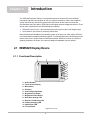
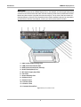
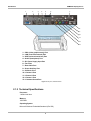

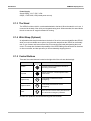


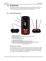
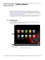
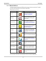
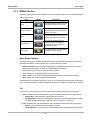
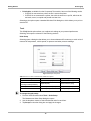

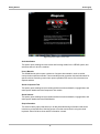


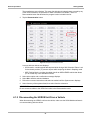
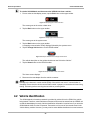

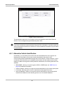
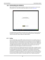

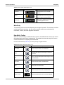


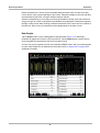

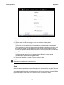
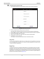

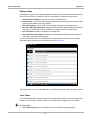


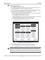

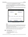
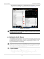

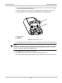
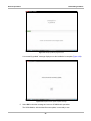
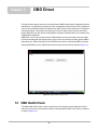
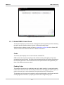
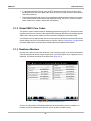


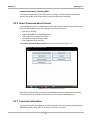
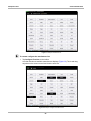
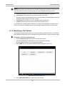
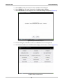
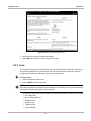

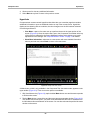

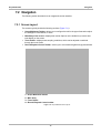
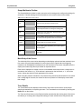
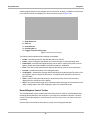


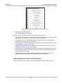

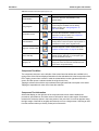
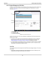
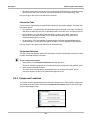
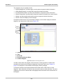


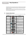
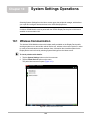


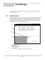
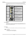


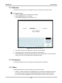

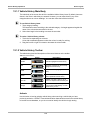
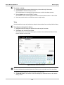
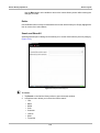


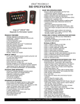


![VERUS PRO User Manual [3980kb PDF File] - Snap](http://vs1.manualzilla.com/store/data/005690474_1-9ff68923f14d7698ce72469cabae3990-150x150.png)