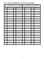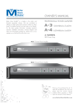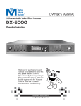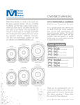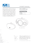
1
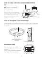
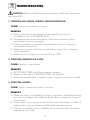
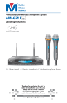
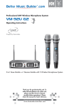
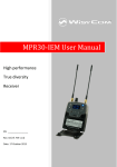
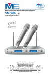
®
®
Unlike any others ... that’s cost & value for you
Professional UHF Wireless Microphone System
VM-82U G3
Operating Instructions
G3 SERIES
Generation 3
UHF
Frequency Selectable
U
HF
W
LE
835.
500
IRE
BA
T
SS
SY
ST
EM
VM
-8
2U
G3
MICROPHONE 1
IR
PEAK
UHF
VOLUME
MIN
MAX
RF
µV
100
PEAK
%
100
60
60
25
25
5
5
DEV
®
FREQUENCY SYNC MUTE
835.500
CH:01 SQ:6
ANT
A
GHz
MHz
ANT
B
FREQUENCY
CHANNEL
SQUELCH
BOOSTER FREQ
STANDBY
REMOTE
MICROPHONE 2
Better Music Builder
®
Passionate about Music
PEAK
FREQ
VOLUME
SET
VM-82U G3
2-IN-1 BASE RECEIVER MODULE
MIN
MAX
RF
µV
100
PEAK
%
100
60
60
25
25
5
5
DEV
FREQUENCY SYNC MUTE
850.700
CH:03 SQ:3
ANT
A
GHz
MHz
ANT
B
FREQUENCY
CHANNEL
SQUELCH
BOOSTER FREQ
STANDBY
REMOTE
FREQ
POWER
SET
ESC
2-in-1 Base Module ***1 Receive Module with 2 Wireless Microphones System
Thank you for purchasing this unit. To
make full and effective use of this unit,
please read this Owner's Manual
carefully before operating it. Please
retain this manual for future reference.
Passionate about Music
www.BetterMusicBuilder.com
CONTENTS
INTRODUCTION................................................................................ 1
Intro
SYSTEM FEATURES............................................................................. 1
Features
Package
Base Module
hand-held
Operation
PACKAGE ACCESSORIES................................................................... 2
2-in-1 BASE MODULE........................................................................ 3
• Controls and Functions................................................................. 3~4
• Hardware Setup.............................................................................5~6
HAND-HELD MICROPHONE.............................................................. 7
• Controls and Functions................................................................. 7~8
OPERATION...................................................................................... 9
• How to Set Up Microphone Frequency.......................................... 9
• How to Lock/unlock Receiver’s Settings........................................10
• How to Adjust Microphone Volume...............................................11
• How to Adjust Squelch.....................................................................11
• How to Insert/change Batteries of Microphone.......................... 12
• How to Turn On/Off Microphone................................................. 13
• How to Interchange Microphone Head........................................13
TECHNICAL SPECIFICATION............................................................ 14
Spec
BODY-PACK MICROPHONE (Optional)...................................... 15~16
Body-Pack
TROUBLESHOOTING................................................................. 17~18
Troubleshooting
APPENDIX................................................................................. 19~20
Appendix
WARRANTY..................................................................................... 21
Warranty
CONTACT INFORMATION............................................................... 22
Contact Us
INTRODUCTION
Intro
Better Music Builder VM-82U G3 is a third generation wireless microphone that
uses the latest UHF wireless technology. It is the most advanced and
customizable wireless microphone system we have to offer. Its sleek design
features heavy duty UHF dual-channel microphones, built-in LCD panels,
Wireless Infrared Auto Sync System, 30 unique channels for each microphone,
and ultra long battery life.
Don’t make setting up harder on you! Use the Wireless Infrared Auto Sync
System for a hassle-free setup. Say good bye to having to adjust the
microphone’s frequency. With a touch a button, the microphone automatically
synchronizes with the receiver to create a complete interference free and crystal
clear microphone system. The VM-82U G3 Wireless Microphone also features
the ability to lock on to your personal favorite settings.
Clear Voice delivers crystal clearer sound quality that pro audio engineers trust.
It automatically enhances the sound of the vocal by detecting and eliminating
artifact noises. The result is a sound closer resembles that of a wired
microphone. What you get is a cleaner and clearer sound at all audio levels.
Better Music Builder is committed in always seeking new ways to make our
products better. We are well aware of short battery life among your favorite
microphone systems. Through intensive research we have developed a better
power management system to give our VM-82U G3 a much needed boost in
battery life.
It is simply the best solution for home and professional karaoke performance
Features
SYSTEM FEATURES
1. Equipped with the latest UHF wireless technology and dual-channel in a
2-in-1 Base Module to prevent signal interference.
2. Clear LCD panel displaying Radio Frequency (RF), Audio Frequency (DEV),
Sync, Mute, Lock, Battery, Frequency, Channel, Squelch, and Antenna status.
3. Wireless Infrared Auto Sync System saves you time setting up.
4. Clear Voice technology delivers crystal clearer sound just like a wired
microphone.
5. 60 unique selectable channels!
6. Ability to lock on personal favorite settings.
7. Adjustable antennas for better signal receiving.
8. Up to 8 hours of battery life.
1
PACKAGE ACCESSORIES
Package
The package comes with one 2-in-1 Base Module [Receiver], two handheld
microphones, two antennas, one DC adaptor, one unbalanced audio cable,
and four AA batteries.
MICROPHONE 1
IR
PEAK
UHF
VOLUME
MIN
MAX
RF
µV
100
PEAK
%
100
60
60
25
25
5
5
DEV
®
FREQUENCY SYNC MUTE
835.500
CH:01 SQ:6
ANT
A
GHz
MHz
ANT
B
FREQUENCY
CHANNEL
SQUELCH
BOOSTER FREQ
STANDBY
REMOTE
MICROPHONE 2
Better Music Builder
®
Pa s s i o n a t e a b o u t M u s i c
PEAK
FREQ
VOLUME
SET
VM-82U G3
2-IN-1 BASE RECEIVER MODULE
MIN
MAX
RF
µV
100
PEAK
%
100
60
60
25
25
5
5
DEV
FREQUENCY SYNC MUTE
850.700
CH:03 SQ:3
ANT
A
GHz
MHz
ANT
B
FREQUENCY
CHANNEL
SQUELCH
BOOSTER FREQ
STANDBY
REMOTE
FREQ
POWER
SET
ESC
2-IN-1 BASE MODULE [RECEIVER]: 1 SET
UHF WIRELESS SYSTEM VM-82U G3
BAT
835.500
HANDHELD MICROPHONE: SET of 2
DC POWER ADAPTOR: 1 UNIT
3.54 inches
9 cm
NOTE DC-POWER USAGE: This wireless
microphone system is designed specifically
for the North American market, which use
110V for DC power. If you use this system in
Asia or Europe, you need to change it to
220V by an adaptor with DC-14V output
500mA.
RECEIVING ANTENNA: 2 UNITS
ALKALINE
BATTERY
AUDIO CABLE (FOR MIXED OUT): 1 UNIT
Recommend
ALKALINE
BATTERY
For better quality connections, a XLR
to XLR cable is highly recommended.
AA
ALKALINE
BATTERY
AA
AA
ALKALINE
BATTERY
AA
AA (1.5V) BATTERY: 4 UNITS
2
2-in-1 BASE MODULE [RECEIVER]
Base Module
CONTROLS AND FUNCTIONS
MICROPHONE 1
IR
PEAK
VOLUME
UHF
MAX
MIN
1
RF
µV
100
PEAK
%
100
60
60
25
25
5
5
DEV
2
3
®
FREQUENCY SYNC MUTE
835.500
CH:01 SQ:6
ANT
A
GHz
MHz
ANT
B
FREQUENCY
CHANNEL
SQUELCH
BOOSTER FREQ
STANDBY
REMOTE
MICROPHONE 2
Better Music Builder
®
Pa s s i o n a t e a b o u t M u s i c
PEAK
FREQ
VOLUME
VM-82U G3
SET
2-IN-1 BASE RECEIVER MODULE
4
5
MAX
MIN
RF
6
µV
100
PEAK
%
100
60
60
25
25
5
5
DEV
FREQUENCY SYNC MUTE
850.700
CH:03 SQ:3
ANT
A
GHz
MHz
ANT
B
FREQUENCY
CHANNEL
SQUELCH
BOOSTER FREQ
STANDBY
REMOTE
FREQ
POWER
SET
ESC
7
8
9
10
FRONT PANEL:
1. IR PORT: Broadcasts signal to microphone to allow communication.
2. MIC 1 VOLUME: Controls audio output level.
3. MIC 1 LCD PANEL: Displays system status.
4. MIC 1 SET: Synchronizes frequencies between receiver and microphone.
5. MIC 1 UP“▲”/DOWN“▼”: Selects frequency and squelch.
6. MIC 2 VOLUME: Controls audio output level.
7. MIC 2 LCD PANEL: Displays system status.
8. MIC 2 UP“▲”/DOWN“▼”: Selects frequency and squelch.
9. MIC 2 SET: Synchronizes frequencies between receiver and microphone.
10. POWER: Turns system On/Off.
3
LCD PANEL:
After turning on the “POWER” button, LCD screen will display the following:
11
PEAK
RF
µV
100
PEAK
%
100
60
60
25
25
5
5
DEV
15
12
13
14
FREQUENCY SYNC MUTE
835.500
CH:01 SQ:6
16
17
18
19
GHz
MHz
ANT
A
ANT
B
20
11. SYNC: Shows that synchronization is in progress.
12. MUTE: Shows that microphone is not set up or Off.
13. LOCK/UNLOCK: Shows whether current settings are locked.
14. BATTERY STATUS: Shows battery level of microphone.
15. RF (Radio Frequency): Shows strength indicator of radio signal.
16. DEV (Audio Frequency): Shows strength indicator of incoming audio signal.
17. CHANNEL: Shows current channel.
18. FREQUENCY: Shows current frequency.
19. SQUELCH: Shows coverage range of microphone. The disadvantage of
using a longer range is the increased chance of interference.
20. ANTENNA A/B: Shows the antenna in use. When one antenna
experiences noise or interference, the other antenna takes over.
ANTENNA-B
21
G3 SERIES
Generation 3
362111109800
SERIAL NO.
RISK OF ELECTRIC SHOCK
DO NOT OPEN
Taking apart or modifying the
receiver may lead to electric shock,
fire, or damage to the receiver and
will void your warranty.
MIXED OUTPUT
AUDIO OUTPUT
®
Better Music Builder®
Model No.: VM-82U G3
(UHF Microphone)
CALIFORNIA, UNITED STATES OF AMERICA
E-MAIL: [email protected]
w w w. B e t t e r M u s i c B u i l d e r. c o m
ENGINEERED AND DESIGN IN U.S.A.
MIC 2
MIC 1 + MIC 2
XLR BALANCED
MIC 1 & 2
¼” UNBALANCED
22
23
DC-POWER
AUDIO OUTPUT
REAR PANEL:
MIC 1
DC 12V/600mA
XLR BALANCED
ANTENNA-A
24
25
26
21. ANTENNA-B: Connect antenna to BNC socket here.
22. MIC 2 BALANCED OUTPUT: XLR balanced audio output.
23. MIC 1 & MIC 2 MIXED OUTPUT: Unbalanced ¼ inch audio output.
24. POWER SUPPLY: Removable adapter with DC 12V 600mA.
25. MIC 1 BALANCED OUTPUT: XLR balanced audio output.
26. ANTENNA-A: Connect antenna to BNC socket here.
4
HARDWARE SETUP
Set Up
HOW TO CONNECT AUDIO OUTPUT:
There are three rear outputs as shown in the below diagram:
ANTENNA-B
362111109800
RISK OF ELECTRIC SHOCK
DO NOT OPEN
Taking apart or modifying the
receiver may lead to electric shock,
fire, or damage to the receiver and
will void your warranty.
MIXED OUTPUT
SERIAL NO.
MIC 2
MIC 1 + MIC 2
MIC 1 & 2
¼” UNBALANCED
XLR BALANCED
1
AUDIO OUTPUT
G3 SERIES
Generation 3
AUDIO OUTPUT
®
Better Music Builder®
Model No.: VM-82U G3
(UHF Microphone)
CALIFORNIA, UNITED STATES OF AMERICA
E-MAIL: [email protected]
w w w. B e t t e r M u s i c B u i l d e r. c o m
ENGINEERED AND DESIGN IN U.S.A.
DC-POWER
XLR BALANCED
DC 12V/600mA
2
MIC 2 BALANCED OUTPUT
(XLR BALANCED)
MIC 1
ANTENNA-A
3
MIXED OUTPUT
(¼” UNBALANCED)
MIC 1 BALANCED
OUTPUT (XLR BALANCED)
1. MIC 2 BALANCED OUTPUT is balanced audio output using XLR connection.
The grounding of the balanced XLR connection delivers better quality signal and
reduces unwanted noise. This output enables adjusting MIC 2 effects
independently without affecting MIC 1 effects.
2. MIC 1 & MIC 2 MIXED UNBALANCED OUTPUT is unbalanced audio output
using ¼” connection. In effect, two channels are sharing one single signal. To
produce different effects on each microphone, MIC 1 and MIC 2 need their own
independent signals by using two separate XLR connections.
3. MIC 1 BALANCED OUTPUT is balanced audio output using XLR connection.
The grounding of the balanced XLR connection delivers better quality signal and
reduces unwanted noise. This output enables adjusting MIC 1 effects
independently without affecting MIC 2 effects.
Recommend
We highly recommend using balanced XLR connections if the distance between the
microphone receiver and the amplifier/mixer is more than 10 feet. The grounding of the
balanced XLR connection delivers better quality signal and reduces unwanted noise.
UHF WIRELESS SYSTEM DIAGRAM:
835.500
BAT
UHF WIRELESS SYSTEM VM-82U G3
MIC 1 HANDHELD MICROPHONE
MICROPHONE 2 AUDIO OUT
®
Better Music Builder®
MIC 2 HANDHELD MICROPHONE
MICROPHONE 1 AUDIO OUT
G2 SERIES
Generation 2
Model No.: VM-93C G2
(UHF Microphone)
ANTENNA-A
XLR BALANCED
REAR VIEW
XLR
Balanced Input
CALIFORNIA, UNITED STATES OF AMERICA
E-MAIL: [email protected]
w w w . B e t t e r M u s i c B u i l d e r. c o m
ENGINEERED AND DESIGN IN U.S.A.
ANTENNA-B
360110810500
SERIAL NO.
¼” UNBALANCED
XLR BALANCED
¼” UNBALANCED
RISK OF ELECTRIC SHOCK
DO NOT OPEN
Taking apart or modifying the
receiver may lead to electric shock,
fire, or damage to the receiver and
will void your warranty.
AC-POWER
120V / 60Hz
BALANCED CONNECTION
XLR
Balanced Input
XLR
Balanced Input
XLR
Balanced Input
1/4"
1/4"
1/4"
1/4"
Unbalanced Input Unbalanced Input Unbalanced Input Unbalanced Input
AUDIO MIXER AMPLIFIER OR A KARAOKE UNIT INPUT TERMINAL
5
ANTENNA-B
G3 SERIES
Generation 3
362111109800
RISK OF ELECTRIC SHOCK
DO NOT OPEN
Taking apart or modifying the
receiver may lead to electric shock,
fire, or damage to the receiver and
will void your warranty.
MIXED OUTPUT
AUDIO OUTPUT
®
Better Music Builder®
Model No.: VM-82U G3
(UHF Microphone)
CALIFORNIA, UNITED STATES OF AMERICA
E-MAIL: [email protected]
w w w. B e t t e r M u s i c B u i l d e r. c o m
ENGINEERED AND DESIGN IN U.S.A.
SERIAL NO.
MIC 2
MIC 1 + MIC 2
DC-POWER
MIC 1 & 2
¼” UNBALANCED
XLR BALANCED
AUDIO OUTPUT
HOW TO CONNECT DC-POWER:
MIC 1
XLR BALANCED
DC 12V/600mA
ANTENNA-A
REAR VIEW
For North America Market, use 120V, DC 12V 600mA adaptor. For market
outside North America, use 220V~ 240V DC adaptor with a maximum battery
capacity of 600mA.
NOTE
Please make sure to use the right DC adaptor. Otherwise, it may damage the 2-in-1 Base
Module because the maximum battery capacity is different. The product warranty will be void if
there is damage caused by using the wrong DC adaptor.
OPTIONAL 19” RACK MOUNT KIT:
To put the system onto a mount-kit, please follow the diagram below. Our
special design feature allows it to be mounted on a DJ rack.
ANTENNA IS ADJUSTABLE.
7 inches
MICROPHONE 1
IR
PEAK
UHF
VOLUME
MIN
MAX
RF
µV
100
PEAK
%
100
60
60
25
25
5
5
DEV
®
FREQUENCY SYNC MUTE
835.500
CH:01 SQ:6
ANT
A
GHz
MHz
ANT
B
FREQUENCY
CHANNEL
SQUELCH
BOOSTER FREQ
STANDBY
REMOTE
MICROPHONE 2
Better Music Builder
®
Passionate about Music
PEAK
FREQ
VOLUME
µV
100
PEAK
60
25
25
5
SET
VM-82U G3
2-IN-1 BASE RECEIVER MODULE
MIN
MAX
RF
%
100
60
5
DEV
FREQUENCY SYNC MUTE
850.700
CH:03 SQ:3
16.6 inches
19 inches
RACK MOUNT KIT IS NOT INCLUDED.
6
ANT
A
GHz
MHz
ANT
B
FREQUENCY
CHANNEL
SQUELCH
BOOSTER FREQ
STANDBY
REMOTE
FREQ
POWER
SET
ESC
HANDHELD MICROPHONE
Hand-held
CONTROLS AND FUNCTIONS
BAT
835.500
1
2
835.500
BAT
SYNC
3
UHF WIRELESS SYSTEM VM-82U G3
ALKALINE
BATTERY
ALKALINE
BATTERY
AA
I
AA
4
0
5
I
0
1. INTERCHANGEABLE MICROPHONE HEAD
2. LCD PANEL: Displays system status.
3. IR PORT: Broadcasts signal to receiver to allow communication.
4. BATTERY COMPARTMENT: Insert two AA batteries.
5. POWER: Turns microphone On/Off.
7
LCD PANEL:
After turning on the “POWER”, the LCD panel will light up as below:
BAT
835.500
1
2
3
1. FREQUENCY: Shows current frequency.
2. LED (BATTERY POWER INDICATOR): If green light is on, indicates battery
power is at normal status. If red light is flashing, indicates low battery. No
light means power off or no power.
3. BATTERY STATUS: Shows battery level of microphone.
BATTERY STATUS:
Full Battery
BAT
835.500
Indicates full battery on the microphone. The
engineering team of Better Music Builder uses
the latest technology to indicate the battery
status, so you can see the battery strength.
Low Battery
BAT
835.500
Indicates low battery on the microphone.
When the microphone LCD panel is blinking or
fading, its time to replace the batteries.
BAT
835.500
LCD panel will blink
constantly when battery is
extremely low and about
to die.
NOTE
If the microphone cannot be turn on, please check the battery. It may be very low.
Typical new full battery life is 8 hours with our system, otherwise, the batteries might be defective
or near expiration date.
Batteries are not covered under our product warranty.
8
OPERATION
Operation
HOW TO SET UP MICROPHONE FREQUENCY
Setting up the microphone is quick and easy. Please follow these simple steps:
STEP 1: Press UP “▲”/DOWN “▼” on the receiver to select desired frequency.
MICROPHONE 2
PEAK
VOLUME
MIN
µV
100
%
100
60
60
25
25
5
5
RF
MAX
PEAK
DEV
FREQUENCY SYNC MUTE
850.700
CH:03 SQ:3
ANT
A
FREQUENCY
CHANNEL
SQUELCH
BOOSTER FREQ
STANDBY
REMOTE
GHz
MHz
ANT
B
FREQ
POWER
SET
ESC
STEP 2: Open battery compartment on the microphone. Point MIC’s IR PORT
directly at the receiver’s IR PORT that is located on the upper-left-hand corner.
SYNC
MICROPHONE 1
IR
PEAK
VOLUME
UHF
µV
100
PEAK
60
25
5
MIN
MAX
%
100
60
25
RF
5
DEV
®
FREQUENCY SYNC MUTE
835.500
CH:01 SQ:6
ANT
A
GHz
MHz
ANT
B
FREQUENCY
CHANNEL
SQUELCH
BOOSTER FREQ
STANDBY
REMOTE
MICROPHONE 2
Better Music Builder
®
Pa s s i o n a t e a b o u t M u s i c
PEAK
FREQ
VOLUME
µV
100
PEAK
60
25
5
VM-82U G3
2-IN-1 BASE RECEIVER MODULE
MIN
MAX
RF
%
100
60
25
SET
850.700
BAT
IR
5
DEV
FREQUENCY SYNC MUTE
850.700
CH:03 SQ:3
GHz
MHz
ANT
A
ANT
B
FREQUENCY
CHANNEL
SQUELCH
BOOSTER FREQ
STANDBY
REMOTE
FREQ
POWER
SET
ESC
SYNCING PROCESS
UHF WIRELESS SYSTEM VM-82U G3
STEP 3: Press SET to initiate the synchronization process. The IR PORT will show
red light if it is sync correctly.
MICROPHONE 2
PEAK
VOLUME
MIN
MAX
RF
µV
100
PEAK
%
100
60
60
25
25
5
5
DEV
FREQUENCY SYNC MUTE
850.700
CH:03 SQ:3
ANT
A
GHz
MHz
ANT
B
FREQUENCY
CHANNEL
SQUELCH
BOOSTER FREQ
STANDBY
REMOTE
FREQ
POWER
SET
ESC
NOTE
Each unit is fully tested and qualified by the manufacturer. However, due to the nature of
wireless connection, interference may occur because of local environments and/or radio signals
emitted by other wireless devices within the household.
If MIC 1 or MIC 2 is actively picking up RADIO FREQUENCY (RF) signal when the microphone is
turned off, this is an indication that the frequency is being used by some other active device within
a 200 feet radius. Therefore, selecting a different frequency is highly recommended.
9
HOW TO LOCK/UNLOCK RECEIVER’S SETTINGS
Do the following when the receiver is POWERED OFF.
STEP 1: Press and hold SET on the receiver. Do not release it.
MICROPHONE 2
FREQUENCY
CHANNEL
SQUELCH
BOOSTER FREQ
STANDBY
REMOTE
VOLUME
MIN
FREQ
POWER
SET
MAX
ESC
STEP 2: Then Press POWER on the receiver.
MICROPHONE 2
FREQUENCY
CHANNEL
SQUELCH
BOOSTER FREQ
STANDBY
REMOTE
VOLUME
MIN
FREQ
POWER
SET
MAX
ESC
STEP 3: After the receiver is on, release both buttons to LOCK/UNLOCK
settings.
The LCD panel will show as below:
LOCK
PEAK
µV
100
PEAK
%
100
60
60
25
25
5
5
RF
NOTE
DEV
UNLOCK
FREQUENCY SYNC MUTE
850.700
CH:03 SQ:3
ANT
A
PEAK
GHz
MHz
ANT
B
RF
µV
100
PEAK
%
100
60
60
25
25
5
5
DEV
FREQUENCY SYNC MUTE
850.700
CH:03 SQ:3
ANT
A
GHz
MHz
ANT
B
While the settings are locked, the frequency and the squelch level cannot be changed.
10
HOW TO ADJUST MICROPHONE VOLUME
Turn VOLUME left to decrease the volume and right to increase the volume on
the receiver.
MICROPHONE 2
PEAK
VOLUME
MIN
RF
MAX
Recommend
µV
100
PEAK
%
100
60
60
25
25
5
5
DEV
FREQUENCY SYNC MUTE
850.700
CH:03 SQ:3
ANT
A
GHz
MHz
ANT
B
FREQUENCY
CHANNEL
SQUELCH
BOOSTER FREQ
STANDBY
REMOTE
FREQ
POWER
SET
ESC
We recommend setting the microphone volume to a medium
position, then control the overall volume from the amplifier/mixer.
If the user does any damage to the receiver either accidentally or
intentionally, we have the right to void the warranty.
HOW TO ADJUST SQUELCH
STEP 1: Press
and hold SET on
the receiver. Do
not release it.
STEP 2: Press UP
“▲”/DOWN “▼”
on the receiver to
select the desired
squelch level.
STEP 3: Release
both buttons to
set the squelch
level.
MICROPHONE 2
PEAK
µV
100
PEAK
%
100
60
60
25
25
5
5
RF
DEV
FREQUENCY SYNC MUTE
850.700
CH:03 SQ:0
ANT
A
GHz
MHz
ANT
B
FREQUENCY
CHANNEL
SQUELCH
BOOSTER FREQ
STANDBY
REMOTE
FREQ
POWER
SET
ESC
MICROPHONE 2
PEAK
µV
100
PEAK
%
100
60
60
25
25
5
5
RF
DEV
FREQUENCY SYNC MUTE
850.700
CH:03 SQ:2
ANT
A
GHz
MHz
ANT
B
FREQUENCY
CHANNEL
SQUELCH
BOOSTER FREQ
STANDBY
REMOTE
FREQ
POWER
SET
ESC
MICROPHONE 2
PEAK
RF
µV
100
PEAK
%
100
60
60
25
25
5
5
DEV
FREQUENCY SYNC MUTE
850.700
CH:03 SQ:2
ANT
A
GHz
MHz
ANT
B
FREQUENCY
CHANNEL
SQUELCH
BOOSTER FREQ
STANDBY
REMOTE
FREQ
POWER
SET
ESC
NOTE
SQUELCH (SQ) is used to avoid reproducing noise when the microphone does not
receive enough signals. A value of 0 turns the squelch level off, resulting in more noise and
interference. In contrast, a value of 9 turns the squelch level to the maximum, providing the most
anti-interference ability. However, the drawback of using a higher level of squelch is the reduced
range of the microphone.
11
HOW TO INSERT/CHANGE BATTERIES OF MICROPHONE
STEP 1: Twist and slide open the battery cover.
UHF WIRELESS SYSTEM VM-82U G3
STEP 2: Hold the top of the microphone with one hand and with the other hand
slide two AA batteries into the battery compartment.
ALKALINE
UHF WIRELESS SYSTEM VM-82U G3
BATTERY
AA
Be careful not to drop the microphone while inserting batteries and to follow the polarity
of the battery according to the diagram.
No Good
Good
ALKALINE
BATTERY
AA
ALKALINE
BATTERY
AA
AA
ALKALINE
BATTERY
STEP 3: Slide and twist back the battery cover.
UHF WIRELESS SYSTEM VM-82U G3
12
ALKALINE
BATTERY
AA
HOW TO TURN ON/OFF MICROPHONE
TURN ON: Press the power button and release it immediately to turn ON the
microphone. Microphone’s LCD panel will display frequency, and battery
status.
TURN OFF: Press and hold the power button for 3 seconds to turn OFF the
microphone. Microphone’s LCD panel will turn off.
3 SECONDS
I
I
ON/OFF
0
0
NOTE
If the microphone cannot be powered ON, battery may be low and should be
replaced. Typical battery life is up to 8 hours. Battery life may vary depending on usage.
HOW TO INTERCHANGE MICROPHONE HEAD
NOTE
1
Replacement parts such as the
INTERCHANGEABLE MICROPHONE
HEAD can be purchased from any of
our authorized dealers.
2
INTERCHANGEABLE
MICROPHONE HEAD
850.700
BAT
13
TECHNICAL SPECIFICATION
Spec
A. TECHNICAL FEATURE OF THE 2-IN-1 BASE MODULE:
1.
2.
3.
4.
5.
6.
7.
8.
9.
10.
11.
12.
13.
14.
15.
Frequency Range: UHF 820~990 MHz
Channels: 60
Signal to Noise Ratio: > 90dB
Total Harmonic Distortion: ≤ 1%
Frequency Response: 80Hz ~ 15KHz (±3dB)
Spurious Emission: ≥ 75dB
Receiver Sensitivity: 80dB (12dBuV)
Audio Output Level: Balanced Out: 0~0.5V/600MA
Unbalanced Out: 0~0.5V/5K
Power Supply: 12~16V DC
Current: 300mA
Effective Distance: 100 feet
Operating Temperature: -20°C ~ 40°C
Receiver Dimensions (WxHxD):16.5 x 1.8 x 7.5 (in)/42 x 4.5 x 19 (cm)
Package Dimensions (WxHxD):21.7 x 15.9 x 2.6 (in)/55 x 40.3 x 6.5 (cm)
Shipping Weight: 8.6 lbs / 3.9 kg
B. TECHNICAL FEATURE OF THE MICROPHONE:
1.
2.
3.
4.
5.
6.
Transmitter Power: ≤ 20mV
Max Deviation: ±45kHz
Spurious Emission: -50dB
Battery: 2 x AA 1.5V Alkaline Batteries
Continuous Usage: Up to 8 Hours
Microphone Dimensions (WxH): 9.5 x 2.1 (inches) / 24 x 5.4 (cm)
C. THIS SYSTEM INCLUDES THE FOLLOW:
•
•
•
•
•
•
•
2-in-1 Base Module (receiver): 1 Set
Handheld Microphone: Set of 2
DC-Power Adaptor: 1 Unit
Audio Cable: 1 Unit
Antenna: 2 Units
AA 1.5V Battery: 4 Units
Instructional Manual: 1 Unit
14
Body-Pack
BODY-PACK MICROPHONE SYSTEM
SPECIFICATION (Optional)
NAMES & FUNCTION:
Body-Pack Microphone System (including Lavalier Mic. and Headset Mic.)
Outside Picture
1. Antenna
2. 4-pin Microphone Input Jack
3. LCD Digital Display
4. IR Port: Receives infrared beam
to synchronize frequencies. IR
when using multiple systems,
only one microphone port should
be exposed at a time
5. Battery Cover
6. Tie-Clip
7. Microphone Extension Jack
1
Side-face
Picture
2
3
4
Optional
5
6
7
Optional
Inside Picture
1. Power/Mute indicator
Lavalier Mic.
• Green: Ready
• Amber: Mute Open
• Flashing Red: IR is transmission in
process
• Glowing Red: Low battery power
• Pulsing Red: Battery dead
(microphone cannot be turned off
until batteries are changed)
1
(Accessories)
1/4” to mini 3-pin lavalier cable
2
2. Power ON/OFF/mute switch
Button: Press and hold the
microphone for 3 seconds to turn
power ON/OFF. Press and
release to mute or un-mute the
microphone.
3. Adjustment switch
4. Battery Slot
3
Optional
4
Headset Mic.
Optional
(Accessories)
1/4” to mini 3-pin lavalier cable
Body-pack Microphone Top View
Apical Panel
1. Antenna Jack
2. Power/Mute indicator
3. Power Switch
4. Microphone Input Jack
1
2
3
15
4
Optional
HOW TO INSERT BODY-PACK MICROPHONE BATTERIES
STEP 1: Open battery cover.
Good
STEP 2: Insert 2 AA batteries. 2
alkaline batteries are expected to
use for about 8 hours.
Make sure that you insert batteries
correctly, as shown in picture. When
the microphone body-pack light
glows red, the batteries should be
changed immediately.
AA
ALKALINE
BATTERY
1
ALKALINE
BATTERY
AA
2
CLOSE
AA
ALKALINE
BATTERY
OPEN
HOW TO WEAR BODY-PACK MICROPHONE
The microphone can be buckled to the belt or the guitar band. For best result,
the microphone should be pushed down until the belt is close to the base of
microphone.
B
A
MICROPHONE BODY-PACK
REAR VIEW
ADJUSTMENT GAIN
Three gain settings are available.
Choose the appropriate setting for your
instrument.
• MIC: for the microphone adjustment
• 0: Guitar with passive pickups
• -10: Guitar with active pickups
16
MICROPHONE BODY-PACK
REAR VIEW
TROUBLESHOOTING
Troubleshooting
CAUTION: Before troubleshooting any symptoms, make sure equipments
are turned OFF.
1. SYMPTOM: NO SOUND COMING FROM MICROPHONE
CAUSE: There is no indication of signal.
REMEDIES:
A. Battery may be low and should be recharged by placing the
microphone onto the CHARGER BASE.
B. Microphone and receiver should be in the same channel to allow
transmitting and receiving signal.
C. Volume is turned to a low level and should be turned to a high but
comfortable volume level.
D. Make sure no wires inside the microphone are loose. If so, reconnect
wires if possible.
E. Make sure the microphone is turned ON; not OFF.
2. SYMPTOM: RECEIVER LCD IS OFF.
CAUSE: Receiver is unpowered.
REMEDIES:
A. AC POWER CORD should be connected properly.
B. Make sure the right AC POWER CORD is being used.
C. Determine whether there is indeed current coming from the power outlet.
3. SYMPTOM: NOISES.
CAUSE: There is interference within your area.
REMEDIES:
A. Make sure user is not standing too close to speakers. Microphone being
too close to speakers will create feedback unless microphone volume is
turned down.
B. Audio cable of poor quality should not be used. Switching to a cable of
higher quality such as a balanced XLR cable can reduce noise.
C. Switch to a model that uses a different set of channels when the above
remedies do not work.
17
4. SYMPTOM: DISTORTION IS INCREASING GRADUALLY.
CAUSE: Battery is running low.
REMEDIES:
A. Recharge battery as soon as possible.
B. Make sure to fully charge battery before use.
5. SYMPTOM: POOR SIGNAL.
CAUSE: Objects can be disrupting communication between receiver and
microphone.
REMEDIES:
A. Make sure no objects are between receiver and microphone, such as
walls and shelves.
B. Make sure microphone usage is not in perimeter of police, fire or radio
stations.
C. Devices that send out radio signals can be disruptive, such as cell
phones, radios, computers, etc.
D. Switch to a model that uses a different set of channels when the above
remedies do not work.
18
Appendix
APPENDIX
VM-82U G3 FCC FREQUENCY: 820.000~990.000 MHz
UHF Frequencies Available for Use for Home Electronics in North America
The RF radio frequencies used in the transmission of wireless information are
closely regulated in most countries including North America. A lot of countries
strictly enforce their regulations stating which RF frequencies are available for
use for certain device, so it can help limit the amount of radio frequency
interference in all wireless communications.
Please refer to the following table for MIC 1 and MIC 2 with available RF
frequencies. If the RF frequencies indicated in the following table are in conflicts
with the local wireless information law in your country, please switch to a
different product model or contact our technicians for advice.
FCC Information to User for Reference
This equipment is designed in compliance with the limits for a Class A digital
device pursuant to part 15 of the FCC Rules from the United States of America.
These limits are designed to provide protection against harmful interference
when the equipment is operated in public environment. This equipment
generates, uses, and can radiates radio frequency energy and, if not installed
and used in accordance with the instruction manual, may cause harmful
interference to radio communications. Operation of this equipment in a
residential area may cause harmful interference, so the user will have to correct
the interference at his/her own expense.
19
MIC 1 & MIC 2 FREQUENCY: 820.000~990.000 MHz
MIC 1 FREQUENCY 835~850MHz
MIC 2 FREQUENCY 850~865MHz
CH
FREQUENCY
CH
FREQUENCY
CH
FREQUENCY
CH
FREQUENCY
1
835.500
16
842.525
1
849.950
16
857.300
2
836.300
17
842.850
2
850.425
17
857.875
3
836.650
18
843.450
3
850.700
18
858.225
4
837.250
19
843.825
4
8511.00
19
858.650
5
837.700
20
844.300
5
851.500
20
859.100
6
838.250
21
844.800
6
852.225
21
859.500
7
838.475
22
845.100
7
852.725
22
859.950
8
838.850
23
845.900
8
853.200
23
860.350
9
839.300
24
846.500
9
853.900
24
860.750
10
839.800
25
847.300
10
854.300
25
861.000
11
840.175
26
847.750
11
854.900
26
861.650
12
840.525
27
848.225
12
855.275
27
863.125
13
840.850
28
848.750
13
855.750
28
863.500
14
841.200
29
849.300
14
856.175
29
864.100
15
841.825
30
849.650
15
856.725
30
864.900
20
WARRANTY
Warranty
One-Year Limited Warranty for Home Use Equipment
Our one-year warranty applies to speakers, amplifiers, mixers and microphones for
home use only. It covers both parts and labors. The warranty becomes effective on
the date of your purchase.
Our warranty only covers defects due to product defectiveness with free of defects
in materials or workmanship. However, our warranty does not cover defects due to
normal wears, damage in transit, improper use, abuse or failure to follow the proper
instructions for maintenance. This warranty is void in the event of unauthorized
repairs, alternations, modifications and removing of the product label.
Please also note that our warranty does not cover any shipping cost for the return of
defective products to us for inspection, repair and maintenance. Our warranty for
Better Music Builder products can only be executed in North America.
NOTE
Our warranty does not cover the battery for wireless microphone products.
90-Day Limited Warranty for Public and Commercial Use Equipment
Our 90-day warranty applies to speakers, amplifiers, mixers and microphones for
both public and commercial use such as restaurant, coffee shop, KTV nightclub,
church and school, etc. It covers both parts and labors. The warranty becomes
effective on the date of your purchase.
To Register Your Warranty
Please submit the warranty card that cames with your unit; it is also download on
our website . However, we need the invoice for your purchase in order to process
this warranty. You may also register your warranty online.
Please visit our website at w w w.B et terM usic B uil d er.com.
PRECAUTION
1. If using more than one microphone system, please select the operating
frequency or signal channel carefully so as to avoid disturbing.
2. The input power voltage of the 2-in-1 Base Module is 110V/120V (±10%). If it is
too low or too high, it will affect the work of the machine.
3. When installing batteries, reversing the electrode will damage the machine.
RISK OF ELECTRIC SHOCK
DO NOT OPEN
Caution: To reduce the risk of electrical shock, do not
remove the cover (or back). No user serviceable parts
inside: refer servicing to qualified personnel.
Warning: To reduce the risk of fire or electrical shock,
do not expose this appliance to rain or moisture.
21
This symbol, wherever it appears, alerts
you to the presence of uninsulated
dangerous voltage inside the enclosure
voltage that may be sufficient to
constitute a risk of shock.
This symbol, wherever it appears, alerts
you to important operating and
maintenance instructions in the
accompanying literature. Read the
manual.
CONTACT INFORMATION
Contact Us
MAILING ADDRESS
BETTER MUSIC BUILDER
29300 Kohoutek Way #150
Union City, CA 94587
U.S.A.
TELEPHONE NUMBERS
USA Region
USA Toll Free: 1-800-318-2218
Sales & Marketing: 510-477-9955
Customer Service: 510-477-9955
FAX NUMBERS
USA Region
Sales & Marketing: 510-477-9922
Customer Service: 510-477-9922
WORLD WIDE WEB
E-mail: [email protected]
Website: www.bettermusicbuilder.com
22
MAINTENANCE
NOTE
23
Better Music Builder is a leader in the Audio and
Karaoke equipment industry. We are committed
to offering you high quality audio products. We
may update our manual, so we highly
recommend you to download the free update
from our website at www.BetterMusicBuilder.com.
®
®
Unlike any others ... that’s cost & value for you
Passionate about Music
www.BetterMusicBuilder.com
364110609200
362111109800
Code: 20111122
Printed on 100% Recycled Paper Comments E-mail to [email protected] Copyright © 2012 Better Music Builder. All rights reserved. Legal trademark.