1
53-1003126-02
15 August 2014
Access Gateway
Administrator's Guide
Supporting Fabric OS v7.3.0
© 2014, Brocade Communications Systems, Inc. All Rights Reserved.
Brocade, the B-wing symbol, Brocade Assurance, ADX, AnyIO, DCX, Fabric OS, FastIron, HyperEdge, ICX, MLX, MyBrocade, NetIron,
OpenScript, VCS, VDX, and Vyatta are registered trademarks, and The Effortless Network and the On-Demand Data Center are trademarks
of Brocade Communications Systems, Inc., in the United States and in other countries. Other brands and product names mentioned may be
trademarks of others.
Notice: This document is for informational purposes only and does not set forth any warranty, expressed or implied, concerning any
equipment, equipment feature, or service offered or to be offered by Brocade. Brocade reserves the right to make changes to this document
at any time, without notice, and assumes no responsibility for its use. This informational document describes features that may not be
currently available. Contact a Brocade sales office for information on feature and product availability. Export of technical data contained in
this document may require an export license from the United States government.
The authors and Brocade Communications Systems, Inc. assume no liability or responsibility to any person or entity with respect to the
accuracy of this document or any loss, cost, liability, or damages arising from the information contained herein or the computer programs that
accompany it.
The product described by this document may contain open source software covered by the GNU General Public License or other open
source license agreements. To find out which open source software is included in Brocade products, view the licensing terms applicable to
the open source software, and obtain a copy of the programming source code, please visit http://www.brocade.com/support/oscd.
Contents
Preface..................................................................................................................................... 7
Document conventions......................................................................................7
Text formatting conventions.................................................................. 7
Command syntax conventions.............................................................. 7
Notes, cautions, and warnings.............................................................. 8
Brocade resources............................................................................................ 9
Contacting Brocade Technical Support.............................................................9
Document feedback........................................................................................ 10
About This Document.............................................................................................................. 11
Supported hardware and software.................................................................. 11
What’s new in this document.......................................................................... 11
Key terms for Access Gateway....................................................................... 12
Access Gateway Basic Concepts..............................................................................................15
Brocade Access Gateway overview ...............................................................15
Comparing Native Fabric and Access Gateway modes......................15
Fabric OS features in Access Gateway mode................................................ 17
Buffer credit recovery support............................................................. 20
Forward error correction support.........................................................20
Virtual Fabrics support........................................................................ 21
Device authentication support.............................................................21
AG mode without all POD licenses..................................................... 23
Password distribution support............................................................. 23
FDMI support...................................................................................... 24
Access Gateway port types.............................................................................24
Comparison of Access Gateway ports to standard switch ports ........ 24
Access Gateway hardware considerations..................................................... 26
Configuring Ports in Access Gateway Mode..............................................................................27
Enabling and disabling Access Gateway mode.............................................. 27
Port state description.......................................................................... 28
Access Gateway mapping...............................................................................29
Port mapping.......................................................................................29
F_Port Static Mapping.........................................................................36
Device mapping.................................................................................. 37
Considerations for Access Gateway mapping.................................... 44
N_Port configurations......................................................................................46
Displaying N_Port configurations........................................................ 47
Unlocking N_Ports ............................................................................. 47
Persisting port online state .................................................................47
D_Port support................................................................................................ 48
Limitations and considerations............................................................48
Saving port mappings ........................................................................ 49
Managing Policies and Features in Access Gateway Mode....................................................... 51
Access Gateway Administrator's Guide
53-1003126-02
3
Access Gateway policies overview............................................................... 51
Displaying current policies ............................................................... 51
Access Gateway policy enforcement matrix .................................... 51
Advanced Device Security policy ................................................................. 52
How the ADS policy works................................................................ 52
Enabling and disabling the ADS policy............................................. 52
Allow lists.......................................................................................... 53
ADS policy considerations................................................................ 55
Upgrade and downgrade considerations for the ADS policy............ 55
Automatic Port Configuration policy ............................................................. 55
How the APC policy works................................................................ 55
Enabling and disabling the APC policy............................................. 55
APC policy considerations................................................................ 56
Upgrade and downgrade considerations for the APC policy............ 56
Port Grouping policy......................................................................................56
How port groups work....................................................................... 57
Adding an N_Port to a port group..................................................... 58
Deleting an N_Port from a port group............................................... 58
Removing a port group .....................................................................58
Renaming a port group..................................................................... 59
Disabling the Port Grouping policy....................................................59
Port Grouping policy modes..............................................................59
Creating a port group and enabling Automatic Login Balancing
mode............................................................................................60
Enabling MFNM mode...................................................................... 61
Disabling MFNM mode......................................................................61
Displaying the current MFNM mode timeout value........................... 61
Setting the current MFNM mode timeout value.................................61
Port Grouping policy considerations................................................. 61
Upgrade and downgrade considerations for the Port Grouping
policy........................................................................................... 62
Device Load Balancing policy....................................................................... 62
Enabling the Device Load Balancing policy...................................... 62
Disabling the Device Load Balancing policy..................................... 63
Device Load Balancing policy considerations................................... 63
Persistent ALPA policy..................................................................................63
Enabling the Persistent ALPA policy.................................................64
Disabling the Persistent ALPA policy................................................ 64
Persistent ALPA device data.............................................................64
Clearing ALPA values....................................................................... 65
Persistent ALPA policy considerations..............................................65
Failover policy............................................................................................... 65
Failover with port mapping................................................................ 66
Failover with device mapping ...........................................................69
Enabling and disabling the Failover policy on an N_Port..................70
Enabling and disabling the Failover policy for a port group.............. 71
Upgrade and downgrade considerations for the Failover policy....... 71
Failback policy...............................................................................................71
Failback policy configurations in Access Gateway............................72
Enabling and disabling the Failback policy on an N_Port ................ 73
Enabling and disabling the Failback policy for a port group..............74
Upgrade and downgrade considerations for the Failback policy...... 74
Failback policy disabled on unreliable links (N_Port monitoring)...... 74
Trunking in Access Gateway mode...............................................................75
How trunking works...........................................................................75
Configuring trunking on the Edge switch.......................................... 75
Configuration management for trunk areas...................................... 76
Enabling trunking ............................................................................. 77
4
Access Gateway Administrator's Guide
53-1003126-02
Disabling F_Port trunking....................................................................78
Monitoring trunking .............................................................................78
AG trunking considerations for the Edge switch................................. 78
Trunking considerations for Access Gateway mode........................... 81
Upgrade and downgrade considerations for trunking in Access
Gateway mode.............................................................................. 81
Adaptive Networking on Access Gateway...................................................... 82
QoS: Ingress rate limiting ...................................................................82
QoS: SID/DID traffic prioritization .......................................................82
Upgrade and downgrade considerations for Adaptive Networking
in AG mode....................................................................................83
Adaptive Networking on Access Gateway considerations.................. 83
Per-Port NPIV login limit................................................................................. 84
Setting the login limit........................................................................... 84
Duplicate PWWN handling during device login...............................................84
Performance Monitoring..................................................................................85
Flow Monitor........................................................................................85
Legacy performance monitoring features............................................86
Considerations for the Brocade 6505 and 6510..............................................88
SAN Configuration with Access Gateway.................................................................................. 89
Connectivity of multiple devices overview.......................................................89
Considerations for connecting multiple devices.................................. 89
Direct target attachment..................................................................................89
Considerations for direct target attachment........................................ 90
Target aggregation..........................................................................................91
Access Gateway cascading............................................................................ 92
Access Gateway cascading considerations........................................ 92
Fabric and Edge switch configuration............................................................. 93
Verifying the switch mode................................................................... 93
Enabling NPIV on M-EOS switches.................................................... 94
Connectivity to Cisco fabrics........................................................................... 94
Enabling NPIV on a Cisco switch........................................................94
Rejoining Fabric OS switches to a fabric........................................................ 95
Reverting to a previous configuration..................................................95
Troubleshooting......................................................................................................................97
Index...................................................................................................................................... 99
Access Gateway Administrator's Guide
53-1003126-02
5
6
Access Gateway Administrator's Guide
53-1003126-02
Preface
● Document conventions......................................................................................................7
● Brocade resources............................................................................................................ 9
● Contacting Brocade Technical Support.............................................................................9
● Document feedback........................................................................................................ 10
Document conventions
The document conventions describe text formatting conventions, command syntax conventions, and
important notice formats used in Brocade technical documentation.
Text formatting conventions
Text formatting conventions such as boldface, italic, or Courier font may be used in the flow of the text
to highlight specific words or phrases.
Format
Description
bold text
Identifies command names
Identifies keywords and operands
Identifies the names of user-manipulated GUI elements
Identifies text to enter at the GUI
italic text
Identifies emphasis
Identifies variables and modifiers
Identifies paths and Internet addresses
Identifies document titles
Courier font
Identifies CLI output
Identifies command syntax examples
Command syntax conventions
Bold and italic text identify command syntax components. Delimiters and operators define groupings of
parameters and their logical relationships.
Convention
Description
bold text
Identifies command names, keywords, and command options.
italic text
Identifies a variable.
Access Gateway Administrator's Guide
53-1003126-02
7
Notes, cautions, and warnings
Convention
Description
value
In Fibre Channel products, a fixed value provided as input to a command
option is printed in plain text, for example, --show WWN.
[]
Syntax components displayed within square brackets are optional.
Default responses to system prompts are enclosed in square brackets.
{x|y|z}
A choice of required parameters is enclosed in curly brackets separated by
vertical bars. You must select one of the options.
In Fibre Channel products, square brackets may be used instead for this
purpose.
x|y
A vertical bar separates mutually exclusive elements.
<>
Nonprinting characters, for example, passwords, are enclosed in angle
brackets.
...
Repeat the previous element, for example, member[member...].
\
Indicates a “soft” line break in command examples. If a backslash separates
two lines of a command input, enter the entire command at the prompt without
the backslash.
Notes, cautions, and warnings
Notes, cautions, and warning statements may be used in this document. They are listed in the order of
increasing severity of potential hazards.
NOTE
A Note provides a tip, guidance, or advice, emphasizes important information, or provides a reference
to related information.
ATTENTION
An Attention statement indicates a stronger note, for example, to alert you when traffic might be
interrupted or the device might reboot.
CAUTION
A Caution statement alerts you to situations that can be potentially hazardous to you or cause
damage to hardware, firmware, software, or data.
DANGER
A Danger statement indicates conditions or situations that can be potentially lethal or
extremely hazardous to you. Safety labels are also attached directly to products to warn of
these conditions or situations.
8
Access Gateway Administrator's Guide
53-1003126-02
Brocade resources
Brocade resources
Visit the Brocade website to locate related documentation for your product and additional Brocade
resources.
You can download additional publications supporting your product at www.brocade.com. Select the
Brocade Products tab to locate your product, then click the Brocade product name or image to open the
individual product page. The user manuals are available in the resources module at the bottom of the
page under the Documentation category.
To get up-to-the-minute information on Brocade products and resources, go to MyBrocade. You can
register at no cost to obtain a user ID and password.
Release notes are available on MyBrocade under Product Downloads.
White papers, online demonstrations, and data sheets are available through the Brocade website.
Contacting Brocade Technical Support
As a Brocade customer, you can contact Brocade Technical Support 24x7 online, by telephone, or by email. Brocade OEM customers contact their OEM/Solutions provider.
Brocade customers
For product support information and the latest information on contacting the Technical Assistance
Center, go to http://www.brocade.com/services-support/index.html.
If you have purchased Brocade product support directly from Brocade, use one of the following methods
to contact the Brocade Technical Assistance Center 24x7.
Online
Telephone
E-mail
Preferred method of contact for nonurgent issues:
Required for Sev 1-Critical and Sev
2-High issues:
[email protected]
• My Cases through MyBrocade
•
Continental US: 1-800-752-8061
• Software downloads and licensing •
tools
Europe, Middle East, Africa, and
Asia Pacific: +800-AT FIBREE
(+800 28 34 27 33)
• Knowledge Base
•
For areas unable to access toll
free number: +1-408-333-6061
•
Toll-free numbers are available in
many countries.
Please include:
•
Problem summary
•
Serial number
•
Installation details
•
Environment description
Brocade OEM customers
If you have purchased Brocade product support from a Brocade OEM/Solution Provider, contact your
OEM/Solution Provider for all of your product support needs.
• OEM/Solution Providers are trained and certified by Brocade to support Brocade® products.
• Brocade provides backline support for issues that cannot be resolved by the OEM/Solution Provider.
Access Gateway Administrator's Guide
53-1003126-02
9
Document feedback
• Brocade Supplemental Support augments your existing OEM support contract, providing direct
access to Brocade expertise. For more information, contact Brocade or your OEM.
• For questions regarding service levels and response times, contact your OEM/Solution Provider.
Document feedback
To send feedback and report errors in the documentation you can use the feedback form posted with
the document or you can e-mail the documentation team.
Quality is our first concern at Brocade and we have made every effort to ensure the accuracy and
completeness of this document. However, if you find an error or an omission, or you think that a topic
needs further development, we want to hear from you. You can provide feedback in two ways:
• Through the online feedback form in the HTML documents posted on www.brocade.com.
• By sending your feedback to [email protected].
Provide the publication title, part number, and as much detail as possible, including the topic heading
and page number if applicable, as well as your suggestions for improvement.
10
Access Gateway Administrator's Guide
53-1003126-02
About This Document
● Supported hardware and software.................................................................................. 11
● What’s new in this document.......................................................................................... 11
● Key terms for Access Gateway....................................................................................... 12
Supported hardware and software
In those instances in which procedures or parts of procedures documented here apply to some switches
but not to others, this guide identifies which switches are supported and which are not.
Although many different software and hardware configurations are tested and supported by Brocade
Communications Systems, Inc., for Fabric OS, documenting all possible configurations and scenarios is
beyond the scope of this document.
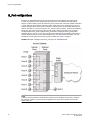
All Fabric OS switches must be running Fabric OS v7.0.0 or later; all M-EOS switches must be running
M-EOSc 9.1 or later, M-EOSn must be running 9.6.2 or later, and Cisco switches with NX OS must be
running 5.x or later.
Fabric OS version 7.3.0 supports the following Brocade hardware platforms for Access Gateway:
•
•
•
•
•
•
•
•
•
•
•
•
•
•
Brocade 300
Brocade 5100
Brocade M5424
Brocade 5430
Brocade 5431
Brocade 5450
Brocade 5460
Brocade 5470
Brocade 5480
Brocade 6505
Brocade M6505
Brocade 6510
Brocade 6547
Brocade VA-40FC
What’s new in this document
The following information has been added since this document was last released:
•
•
•
•
AG mode is supported without all POD licenses.
Password distribution is supported.
Dynamic D_Port is supported.
FDMI is supported.
Access Gateway Administrator's Guide
53-1003126-02
11
Key terms for Access Gateway
Changes made for Fabric OS 7.3.0a
The following content is new or significantly revised from 53-1003126-01 for this release of this
document:
• Updated Key terms for Access Gateway on page 12.
Key terms for Access Gateway
For definitions of SAN-specific terms, visit the Storage Networking Industry Association online
dictionary at:
http://www.snia.org/education/dictionary
For definitions specific to Brocade and Fibre Channel, refer to the Brocade Glossary .
The following terms are used in this manual to describe Access Gateway mode and its components.
12
Access
Gateway
(AG)
Advanced
Device
Security
(ADS) policy
Device
Fabric OS mode for switches that reduces storage area network (SAN)
deployment complexity by leveraging N_Port ID Virtualization (NPIV).
D_Port
A port configured as a diagnostic port on an AG switch, connected fabric
switch, or connected cascaded AG switch to run diagnostic tests between
the ports and test the link.
E_Port
An interswitch link (ISL) port. A switch port that connects switches together
to form a fabric.
Edge switch
A fabric switch that connects host, storage, or other devices, such as
Brocade Access Gateway, to the fabric.
Fabric
system
A fabric system consists of interconnected nodes that look like a single
logical unit when viewed collectively. This refers to a consolidated highperformance network system consisting of coupled storage devices,
networking devices and parallel processing high bandwidth interconnects
such as 4-Gbps, 8-Gbps, 10-Gbps, and 16-Gbps Fibre channel ports.
F_Port
A fabric port. A switch port that connects a host, host bus adapter (HBA), or
storage device to the SAN. On Brocade Access Gateway, the F_Port
connects to a host or a target.
FCoE
Fibre Channel over Ethernet (FCoE) refers to a network technology that
encapsulates Fibre Channel frames over Ethernet networks. This allows
Fibre Channel to use 10-Gigabit Ethernet or higher speed networks while
preserving the Fibre Channel protocol.
Mapping
In Access Gateway, mapping defines the routes between devices or
F_Ports to the fabric facing ports (N_Ports).
N_Port
A node port. A Fibre Channel host or storage port in a fabric or point-to-point
connection. On Brocade Access Gateway, the N_Port connects to the Edge
switch.
Advanced Device Security (ADS) is a security policy that restricts access to
the fabric at the AG level to a set of authorized devices.
Any host or target device with a distinct WWN. Devices may be physical or
virtual.
Access Gateway Administrator's Guide
53-1003126-02
About This Document
NPIV
N_Port ID Virtualization. This is a Fibre Channel facility allowing multiple
N_Port IDs to share a single physical N_Port. This allows multiple Fibre
Channel initiators to occupy a single physical port, easing hardware
requirements in storage area network design, especially for virtual SANs.
Port
Grouping
(PG) policy
Port Grouping (PG) policy is used to partition the fabric, host, or target ports
within an AG-enabled module into independently operated groups.
Access Gateway Administrator's Guide
53-1003126-02
13
Key terms for Access Gateway
14
Access Gateway Administrator's Guide
53-1003126-02
Access Gateway Basic Concepts
● Brocade Access Gateway overview ...............................................................................15
● Fabric OS features in Access Gateway mode................................................................ 17
● Access Gateway port types.............................................................................................24
● Access Gateway hardware considerations..................................................................... 26
Brocade Access Gateway overview
Brocade Access Gateway (AG) is a Fabric OS feature that you can use to configure your Enterprise
fabric to handle additional devices instead of domains. You do this by configuring F_Ports to connect to
the fabric as N_Ports, which increases the number of device ports you can connect to a single fabric.
Multiple AGs can connect to the DCX enterprise-class platform, directors, and switches.
Access Gateway is compatible with M-EOS v9.1 or v9.6 or later, and Cisco-based fabrics that support
standards-based NPIV. You can use the command line interface (CLI), Web Tools, or Brocade Network
Advisor (BNA) to enable and disable AG mode and configure AG features on a switch. This document
describes configurations using the CLI commands. Refer to the Fabric OS Command Reference , the
Web Tools Administrator’s Guide, or the Brocade Network Advisor User Guide for more information
about AG support in those tools.
After you set a Fabric OS switch to AG mode, the F_Ports connect to the Enterprise fabric as N_Ports
rather than as E_Ports.
Comparing Native Fabric and Access Gateway modes on page 15 shows a comparison of a
configuration that connects eight hosts to a fabric using AG to the same configuration with Fabric OS
switches in Native mode.
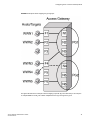
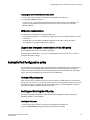
Switches in AG mode are logically transparent to the host and the fabric. Therefore, you can increase
the number of hosts that have access to the fabric without increasing the number of switch domains.
This simplifies configuration and management in a large fabric by reducing the number of domain IDs
and ports.
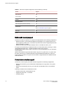
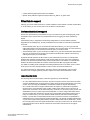
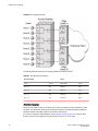
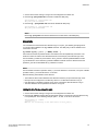
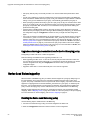
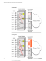
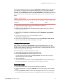
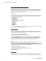
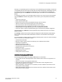
Comparing Native Fabric and Access Gateway modes
The following points summarize the differences between a Fabric OS switch functioning in Native
operating mode and a Fabric OS switch functioning in AG operating mode:
• The Fabric OS switch in Native mode is a part of the fabric; it requires two to four times as many
physical ports, consumes fabric resources, and can connect to a Fabric OS fabric only.
• A switch in AG mode is outside of the fabric; it reduces the number of switches in the fabric and the
number of required physical ports. You can connect an AG switch to a Fabric OS, M-EOS, or Ciscobased fabric.
Refer to the figures below for a comparison between switch function in Native mode and switch function
in AG mode.
Access Gateway Administrator's Guide
53-1003126-02
15
Access Gateway Basic Concepts
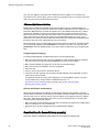
FIGURE 1 Switch function in Native mode
16
Access Gateway Administrator's Guide
53-1003126-02
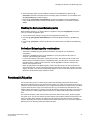
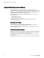
Fabric OS features in Access Gateway mode
FIGURE 2 Switch function in Access Gateway mode
Fabric OS features in Access Gateway mode
In the table below, "Yes" indicates that the feature is supported in Access Gateway mode. "No"
indicates that the feature is not provided in AG mode. "NA" indicates the feature is not applicable in
Access Gateway mode. A single asterisk (*) indicates the feature is transparent to AG; that is, AG
forwards the request to the Enterprise fabric. Two asterisks (**) indicates that the feature may not be
available if the Enterprise fabric is not a Brocade fabric. For more information on these features, refer to
the Fabric OS Administrator's Guide and Fabric OS Command Reference.
TABLE 1 Fabric OS components supported on Access Gateway
1
Feature
Support
Access Control
Yes (limited roles)
Adaptive Networking
Yes
When a switch is behaving as an AG, RBAC features in Fabric OS are available, but there are some limitations. For more information
on the limitations, refer to Access Gateway hardware considerations on page 26.
Access Gateway Administrator's Guide
53-1003126-02
17
Access Gateway Basic Concepts
TABLE 1 Fabric OS components supported on Access Gateway (Continued)
Feature
Support
Admin Domains
No
Audit
Yes
Beaconing
Yes
Bottleneck Detection
Yes
Buffer Credit Recovery (CR)
Yes Refer to Buffer credit recovery support on page 20 .
Config Download/Upload
Yes
Device Authentication
Yes
Refer to Device authentication support on page 21.
DHCP
Yes
Diagnostic Port (D_Port)
Yes
Refer to D_Port support on page 48.
Duplicate PWWN handling during device login
Yes
Refer to Duplicate PWWN handling during device login on
page 84.
Encryption Configuration and Management
No
Environmental Monitor
Yes
Error Event Management
Yes
Extended Fabrics
No
Fabric Assigned PWWN (FA-PWWN)
Yes
Fabric Device Management Interface (FDMI)
Yes*
Fabric Manager
Yes**
Fabric Provisioning
No
Fabric Services
No
Fabric Watch
Yes
Refer to the Fabric Watch Administrator's Guide for
applicable support details.
Fibre Channel Routing (FCR) services
18
No
Access Gateway Administrator's Guide
53-1003126-02
Access Gateway Basic Concepts
TABLE 1 Fabric OS components supported on Access Gateway (Continued)
Feature
Support
FICON (includes CUP)
No
Forward Error Correction (FEC)
Yes
Refer to Forward error correction support on page 20.
High Availability
Yes
Hot Code Load
Yes
License
Yes**
Lightweight Directory Access Protocol (LDAP)
Yes
Log Tracking
Yes
Management Server
NA
Manufacturing Diagnostics
Yes
N_Port ID Virtualization (NPIV)
Yes
Name Server
NA
Native Interoperability Mode
NA
Network Time Protocol (NTP)
No (no relevance from fabric perspective)
Open E_Port
NA
Performance Monitor
Yes
Persistent ALPA
Yes
Port Decommission
No
Port Mirroring
No
QuickLoop, QuickLoop Fabric Assist
No
Remote Authentication Dial-In User Service (RADIUS) Yes
2
Resource Monitor
Yes
Security
Yes (ADS/DCC Policy)
SNMP
Yes
Speed Negotiation
Yes
In embedded switches, time should be updated by the server management utility.
Access Gateway Administrator's Guide
53-1003126-02
19
Buffer credit recovery support
TABLE 1 Fabric OS components supported on Access Gateway (Continued)
Feature
Support
Syslog Daemon
Yes
Track Changes
Yes
Trunking
Yes**
User-Defined Roles
Yes
Value Line Options (Static POD, DPOD)
Yes
Virtual Fabrics
No
Refer to Virtual Fabrics support on page 21 .
Web Tools
Yes
Zoning
NA
Buffer credit recovery support
This Fabric OS feature is supported on 8 Gbps and 16 Gbps platforms in the following configurations:
• Between AG switch F_Port and Brocade HBA port using Adapter v3.2 or greater firmware or any
device supporting credit recovery, This feature only works at the maximum supported speed of the
HBA port (8 Gbps or 16 Gbps).
• Between AG switch N_Port and Brocade fabric switch or cascaded AG switch F_Port.
It is highly recommended that you disable this feature on the AG switch before connecting to a switch
running Fabric OS earlier than 7.1. Enable and disable credit recovery using the
portcfgcreditrecovery command. Refer to the Fabric OS Command Reference for more information
on this command.
Specific switch platforms support this feature either in R_RDY or VC_RDY mode. In VC_RDY mode,
the buffer credit recovery is supported with fabric assigned PWWN (FA-PWWN), FEC, QoS, and
trunking Fabric OS features. In R_RDY mode, this feature is supported without FA-PWWN and QoS
Fabric OS features.
Forward error correction support
Forward error correction (FEC) is a Fabric OS feature supported in the following configurations:
• Between the AG switch F_Port and a Brocade 16 Gbps HBA port running version 3.2 or greater
firmware.
• Between the AG switch N_Port and F_Port on Brocade 16 Gbps fabric switch or cascaded AG
switch.
Following are limitations and considerations for FEC:
• Supported on Brocade 16 Gbps platforms only.
• Supported by Fabric OS 7.1.0 and later.
• Enabled by default.
20
Access Gateway Administrator's Guide
53-1003126-02
Virtual Fabrics support
• A Fabric OS downgrade requires FEC to be disabled.
• Specific switch platforms support this feature either in R_RDY or VC_RDY mode.
Virtual Fabrics support
Although you cannot enable AG mode on a switch enabled for Virtual Fabrics or enable Virtual Fabrics
on an AG switch, you can connect ports on an AG switch to Virtual Fabrics.
Device authentication support
Devices use authentication as a mechanism to log in into switches only after exchanging DH_CHAP
authorization keys. This prevents any unauthorized device from logging into switch and fabric by
default.
Authentication policy is supported in the following configurations for Access Gateway switches.
Regardless of the enabled policy, the AG port disables if the DH-CHAP or FCAP fails to authenticate
each other.
• Access Gateway switch N_Port connected to Brocade fabric switch F_Port. The N_Port should
enable authentication when authentication is enabled on the connected switch. This can be done by
enabling switch policy on the AG switch and device policy on the fabric switch.
• Access Gateway switch F_Port connected to an HBA. The F_Port also should enable authentication
when the connected device is sending login request with authentication enabled. This is done by
enabling device policy on the AG switch.
By default, Brocade switches use DH-CHAP or FCAP authentication protocols. For authentication
between fabric switches and AG switches, FCAP and DH-CHAP are used. If an FCAP certificate is
present on the AG switch and fabric switch, FCAP has precedence over DHCAP. For authentication
between AG switches and HBAs, DH-CHAP is used because the HBA only supports DH-CHAP.
For details on installing FCAP certificates and creating DHCAP secrets on the switch in AG or native
mode, refer to the Fabric OS Administrator’s Guide or Fabric OS Command Reference.
For general information on authentication, refer to the section on authentication policy for fabric
elements in the "Configuring Security Policies" chapter of the Fabric OS Administrator’s Guide.
Supported policy modes
The following switch and device policy modes are supported by Access Gateway:
• On - Strict authentication will be enforced on all ports. The ports on the AG connected to the switch
or device will disable if the connecting switch or device does not support authentication or the policy
mode is set to off. During AG initialization, authentication initiates on all ports automatically.
• Off - The AG switch does not support authentication and rejects any authentication negotiation
request from the connected fabric switch or HBA. A fabric switch with the policy mode set to off
should not be connected to an AG switch with policy mode set to on since the on policy is strict. This
will disable the port if any switch rejects the authentication. You must configure DH-CHAP shared
secrets or install FCAP certificates on the AG and connected fabric switch before switching from a
policy "off" mode to policy "on" mode. Off is the default mode for both switch and device policy.
• Passive - The AG does not initiate authentication when connected to a device, but participates in
authentication if the connecting device initiates authentication. The AG will not initiate authentication
on ports, but accepts incoming authentication requests. Authentication will not disable AG F_Ports if
the connecting device does not support authentication or the policy mode is set to off. Passive mode
is the safest mode to use for devices connected to an AG switch if the devices do not support
authentication.
Access Gateway Administrator's Guide
53-1003126-02
21
Supported Fabric OS commands
To perform authentication with switch policy, the on and off policy modes are supported on the AG
switch. To perform authentication with device policy, the on, off, and passive modes are supported on
the AG switch.
TABLE 2 Behavior of sending AG switch and receiving fabric switch with different policies configured
AG switch with
switch policy
mode on
AG switch with
switch policy off
Fabric switch with device
policy mode ON
Fabric switch with device
policy mode PASSIVE
Fabric switch with device
policy mode OFF
Authorization negotiation accept
Authorization negotiation accept
Authorization negotiation reject
DH-CHAP/FCAP:
DH-CHAP/FCAP:
Success - N_Port
Success - N_Port
N_Port without
authentication
Failure - disable
Failure - disable
No negotiation
No Negotiation
No negotiation
No light
N_Port without authenctication.
N_Port without
authentication
TABLE 3 Behavior of sending device (HBA) and receiving AG switch with different policies
configured
AG switch with device
policy mode ON
AG switch with device
policy mode PASSIVE
AG switch with device
policy mode OFF
Authorization negotiation accept
Authorization negotiation
- reject
DH-CHAP
DH-CHAP
Success - F_Port
Success - F_Port
F_Port without
authentication
Failure - disable
Failure - disable
HBA authentication enabled Authorization negotiation
- accept
HBA authenticationdisabled No negotiation
No light
No negotiation
No negotiation
F_Port without
authentication
F_Port without
authentication
Supported Fabric OS commands
All Fabric OS commands for authentication policy apply to AG switches, including the following:
•
•
•
•
•
authutil -- policy
authutil --show
authutil --set
secauthsecret --set
secauthsecret --show
NOTE
Although authutil --authinit is not supported in AG mode, it is supported in native mode.
22
Access Gateway Administrator's Guide
53-1003126-02
Limitations and considerations
For more information, refer to the Fabric OS Command Reference .
Limitations and considerations
• Authentication policy is not supported on cascaded AG switch configurations.
• Authentication is not supported between an AG switch running Fabric OS v7.1.0 or later and a fabric
running Fabric OS earlier than v7.1.0. If the AG switch is connected to fabric switch running Fabric
OS earlier than v7.1.0, the AG switch N_Ports will disable if authentication is enabled on both
switches. Devices mapped to N_Ports connected to fabrics operating with Fabric OS before v7.1.0
will also disable.
• If authentication is disabled on the Fabric Switch, the AG switch N_Port will come online without
authentication policy.
• Device and switch policies must be disabled on the AG before converting the switch to Native mode.
• Device and switch policies must be disabled on the switch in Native mode before converting it to AG
mode.
• Authentication policy is disabled by default on all ports in AG mode.
• High availability (HA) reboots are supported.
AG mode without all POD licenses
Prior to Fabric OS 7.3.0, the Brocade non-embedded switches (Brocade 300, 5100, 6505, and 6510)
require all POD licenses to run in Access Gateway mode. However, starting with Fabric OS release
7.3.0, all POD licenses are not required to run these switches in AG mode.
The following points need to be considered while running the switches in AG mode without all POD
licenses:
• By default, configured N_Ports will come up as disabled because a POD license is not installed for
those ports.
• All F_Ports mapped to the default N-port will come up as disabled with the following reason N-Port
Offline for F-Port
• You must manually configure N_Ports in the switch using the portcfgnport command, and move the
cable connections accordingly.
• You can update the N_Port-to-F_Port mapping using the mapdel and mapadd commands.
• You must install all POD licenses to downgrade from Fabric OS 7.3.0 to any previous release.
Password distribution support
Prior to Fabric OS 7.3.0, user account and password database can only be managed locally on the
switches in AG mode. You had to either manually populate the password database in the AG mode or
change the switch to native mode and then back to AG mode to populate the password database.
Starting with Fabric OS 7.3.0, running the distribute command on any of the switches in native mode,
will distribute the password database to all AGs and switches connected to the same fabric. You can
distribute using the AG name or use *.* to distribute to all switches and AGs.
Consider the following points regarding password distribution:
• The fddCfg command in the AG can only be used to configure to either accept or reject the
password database coming from any of the switches in the same fabric.
• To accept the password database from any switch, the AG must be loaded with Fabric OS 7.3.0, and
at least one of the switches in native mode within the same fabric must be loaded with Fabric OS
7.3.0.
• Other databases supported by fddCfg are not supported on AGs.
Access Gateway Administrator's Guide
53-1003126-02
23
FDMI support
• VF mode distribution is not applicable to an AG.
• The distribute command is not supported in AG mode. Hence, an AG cannot distribute its
password database to any of the switches in native mode.
FDMI support
Starting with Fabric OS 7.3.0, AG can register its N_Port with FDMI devices, and the fdmishow
command is supported to display the device details in AG as well. The fdmishow command in an AG
will display only the local devices, and the remote device details are blocked.
Access Gateway port types
Access Gateway differs from a typical fabric switch because it is not a switch; instead, it is a mode that
you enable on a switch using the ag command. After a switch is set in Access Gateway mode, it can
connect to the fabric using node ports (N_Ports). Typically, fabric switches connect to the Enterprise
fabric using interswitch link (ISL) ports, such as E_Ports.
AG uses the following Fibre Channel (FC) ports:
• F_Port - Fabric port that connects a host, HBA, or storage device to a switch in AG mode.
• N_Port - Node port that connects a switch in AG mode to the F_Port of the fabric switch.
• D_Port - Port configured in diagnostic mode so that various tests can run between it and connected
D_Port on another switch or HBA across a link.
NOTE
Initiate the portcfgpersisentenable command on all external or outward facing ports to ensure that
these ports come back online after a switch reboot or power failure. For an embedded switch, execute
this command through the chassis management console and not the switch CLI or the command may
not persist. Refer to Persisting port online state on page 47 for more information.
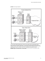
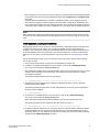
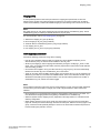
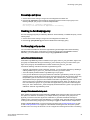
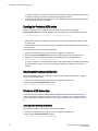
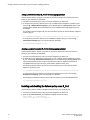
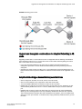
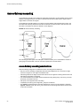
Comparison of Access Gateway ports to standard switch ports
Access Gateway multiplexes host connections to the fabric. It presents an F_Port to the host and an
N_Port to an Edge fabric switch. Using N_Port ID Virtualization (NPIV), AG allows multiple FC
initiators to access the SAN on the same physical port. This reduces the hardware requirements and
management overhead of hosts to the SAN connections.
A fabric switch presents F_Ports (or FL_Ports) and storage devices to the host and presents E_Ports,
VE_Ports, or EX_Ports to other switches in the fabric. A fabric switch consumes SAN resources, such
as domain IDs, and participates in fabric management and zoning distribution. A fabric switch requires
more physical ports than AG to connect the same number of hosts.
The figure below shows a comparison of the types of ports a switch in AG mode uses to the type of
ports that a switch uses in standard mode.
24
Access Gateway Administrator's Guide
53-1003126-02
Access Gateway Basic Concepts
FIGURE 3 Port usage comparison
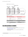
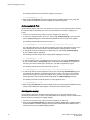
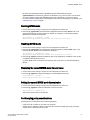
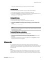
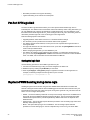
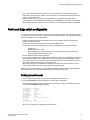
You can convert a Fibre Channel port into a D_Port on AG switch and a connected fabric switch,
another AG switch (cascaded configuration), or an HBA to test the link between the ports. When you
configure the ports on each end of the link as D_Ports, diagnostic tests automatically initiate on the link
when the D_Ports go online. Results can be viewed using Fabric OS commands, such as
portDPortTest, during or after testing. Once in D_Port mode, the port does not participate in fabric
operations, login to a remote device, or run data traffic.
Access Gateway Administrator's Guide
53-1003126-02
25
Access Gateway hardware considerations
FIGURE 4 Diagnostic port configurations
The table below shows a comparison of port configurations between AG and a standard fabric switch.
TABLE 4 Port configurations
Port type Available on Access Gateway?
Available on Fabric switch?
F_Port
Yes Connects hosts and targets to Access
Gateway.
Yes Connects devices, such as hosts, HBAs, and
storage to the fabric.
N_Port
Yes Connects Access Gateway to a fabric
switch.
N/A N_Ports are not supported.
E_Port
N/A ISL is not supported.
Yes Connects the switch to other switches to
form a fabric.
D_Port
Yes Allows diagnostic testing across link to
connected AG switch, fabric switch, or
HBA.
Yes Allows diagnostic testing across link to
connected AG switch.
Access Gateway hardware considerations
Hardware considerations for Access Gateway are as follows:
• Access Gateway is supported on the switch platforms and embedded switch platforms listed in
Supported hardware and software on page 11.
• Loop devices are not supported.
• Direct connections to SAN target devices are only supported if the AG-enabled module is
connected to a fabric.
3
26
The switch is logically transparent to the fabric, therefore it does not participate in the SAN as a fabric switch.
Access Gateway Administrator's Guide
53-1003126-02
Configuring Ports in Access Gateway Mode
● Enabling and disabling Access Gateway mode.............................................................. 27
● Access Gateway mapping...............................................................................................29
● N_Port configurations......................................................................................................46
● D_Port support................................................................................................................ 48
Enabling and disabling Access Gateway mode
Use the following steps to enable and disable Access Gateway mode. After you enable AG mode, some
fabric information is erased, such as the zone and security databases. Enabling AG mode is disruptive
because the switch is disabled and rebooted. For more information on the ag commands used in these
steps, refer to the Fabric OS Command Reference.
1. Connect to the switch and log in using an account assigned to the admin role.
2. Before enabling or disabling a switch to AG mode, save the current configuration file using the
configUpload command in case you might need this configuration again.
3. Ensure that no zoning or Admin Domain (AD) transaction buffers are active. If any transaction buffer
is active, enabling AG mode will fail with the error, "Failed to clear Zoning/Admin Domain
configuration".
4. Verify that the switch is set to Native mode.
a)
b)
Issue the switchShow command to verify the switch mode.
If the switch mode is anything other than 0, issue the interopmode 0 command to set the
switch to Native mode.
For more information on setting switches to Native mode, refer to the Fabric OS
Administrator’s Guide.
5. Enter the switchDisable command.
switch:admin> switchdisable
This command disables all user ports on a switch. All Fibre Channel ports are taken offline. If the
switch is part of a fabric, the remaining switches reconfigure. You must disable the switch before
making configuration changes.
6. Enter the ag - -modeenable command.
switch:admin> ag --modeenable
The switch automatically reboots and comes back online in AG mode using a factory default port
mapping. For more information on AG default port mapping, refer to Table 7 on page 31.
7. Enter the ag --modeshow command to verify that AG mode is enabled.
switch:admin> ag --modeshow
Access Gateway mode is enabled.
You can display the port mappings and status of the host connections to the fabric on Access
Gateway.
8. Enter the ag --mapshow command to display all the mapped ports.
The ag --mapshow command shows all enabled N_Ports, even if those N_Ports are not connected.
Access Gateway Administrator's Guide
53-1003126-02
27
Port state description
9. Enter the switchShow command to display the status and port state of all ports. Refer to the Fabric
OS Command Reference for examples of output. For a description of the port state, refer to Table 5
on page 28.
When you disable AG mode, the switch automatically reboots and comes back online using the
fabric switch configuration; the AG parameters, such as port mapping, and Failover and Failback,
are automatically removed. When the switch reboots, it starts in Fabric OS Native mode. To rejoin
the switch to the core fabric, refer to Rejoining Fabric OS switches to a fabric on page 95.
10.Enter the switchDisable command to disable the switch.
switch:admin> switchdisable
11.Enter the ag command with the --modedisable option to disable AG mode.
switch:admin> ag --modedisable
12.Enter the ag --modeshow command to verify that AG mode is disabled.
switch:admin> ag --modeshow
Access Gateway mode is NOT enabled
Port state description
Refer to the following table to know the port state.
TABLE 5 Port state description
28
State
Description
No _Card
No interface card present
No _Module
No module (GBIC or other) present
Mod_Val
Module validation in process
Mod_Inv
Invalid module
No_Light
Module is not receiving light
No_Sync
Receiving light but out of sync
In_Sync
Receiving light and in sync
Laser_Flt
Module is signaling a laser fault
Port_Flt
Port marked faulty
Diag_Flt
Port failed diagnostics
Lock_Ref
Locking to the reference signal
Testing
Running diagnostics
Offline
Connection not established (only for virtual ports)
Online
Port is up and running
Access Gateway Administrator's Guide
53-1003126-02
Access Gateway mapping
Access Gateway mapping
When operating in AG mode, you must specify pre-provisioned routes that AG will use to direct traffic
from the devices (hosts or targets) on its F_Ports to the ports connected to the fabric using its N_Ports.
This is unlike Native switch mode where the switch itself determines the best path between its F_Ports.
This process of pre-provisioning routes in AG mode is called "mapping."
During mapping, device World Wide Names (WWNs) or F_Ports are assigned to N_Ports and N_Port
groups on the switch running in AG mode. Mapping ensures that a device logging in to the switch will
always connect to the fabric through a specific N_Port or N_Port group. Two types of mapping are
available:
• Port mapping
A specific F_Port is mapped to a specific N_Port. This ensures that all traffic from a specific F_Port
always goes through the same N_Port. To map an F_Port to an N_Port group, simply map the port to
an N_Port that belongs to that port group. All F_Ports mapped to that N_Port will be part of that
N_Port group.
• Device mapping (optional)
A specific device WWN is mapped to N_Port groups (preferred method) or to specific N_Ports.
Device mapping allows a virtual port to access its destination device regardless of the F_Port where
the device resides. Device mapping also allows multiple virtual ports on a single physical machine to
access multiple destinations residing in different fabrics.
Device mapping is optional and should be added on top of existing port maps. Port mapping must
exist at all times.
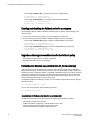
Port mapping
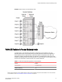
F_Ports must be mapped to N_Ports before the F_Ports can come online. The figure below shows an
example in which eight F_Ports are mapped evenly to four N_Ports on a switch in AG mode. The
N_Ports connect to the same fabric through different Edge switches.
Access Gateway Administrator's Guide
53-1003126-02
29
Default port mapping
FIGURE 5 Port mapping example
The following table describes the port mapping details for the above example.
TABLE 6 Description of port mapping
Access Gateway
Fabric
F_Port
N_Port
Edge switch
F_Port
F_1, F_2
N_1
Switch_A
F_A1
F_3, F_4
N_2
Switch_A
F_A2
F_5, F_6
N_3
Switch_B
F_B1
F_7, F_8
N_4
Switch_B
F_B2
Default port mapping
When you first enable a switch for AG mode, the F_Ports are mapped to a set of predefined N_Ports
by default. The table below describes the default port mapping for all supported hardware platforms.
By default, Failover and Failback policies are enabled on all N_Ports.
If you want to change the default mapping, refer to Adding F_Ports to an N_Port on page 35. Note
that all F_Ports must be mapped to an N_Port before the F_Port can come online.
30
Access Gateway Administrator's Guide
53-1003126-02
Configuring Ports in Access Gateway Mode
NOTE
Prior to Fabric OS 7.3.0, all POD licenses must be present to use the Brocade 300, 5100, 6505, and
6510 as an Access Gateway. However, Fabric OS 7.3.0 does not require all POD licenses to run in AG
mode.
TABLE 7 Access Gateway default port mapping
Brocade Model
Total Ports
F_Ports
N_Ports
Default port mapping
VA-40FC
40
0–31
32–39
0–3 mapped to 32
4–7 mapped to 33
8–11 mapped to 34
12–15 mapped to 35
16–19 mapped to 36
20–23 mapped to 37
24–27 mapped to 38
28–31 mapped to 39
300
24
0–15
16–23
0, 1 mapped to 16
2, 3 mapped to 17
4, 5 mapped to 18
6, 7 mapped to 19
8, 9 mapped to 20
10, 11 mapped to 21
12, 13 mapped to 22
14, 15 mapped to 23
5100
40
0–31
32–39
0, 1, 2, 3 mapped to 32
4, 5, 6, 7 mapped to 33
8, 9, 10, 11 mapped to 34
12, 13, 14, 15 mapped to 35
16, 17, 18, 19 mapped to 36
20, 21, 22, 23 mapped to 37
24, 25, 26, 27 mapped to 28
28, 29, 30, 31 mapped to 39
Access Gateway Administrator's Guide
53-1003126-02
31
Configuring Ports in Access Gateway Mode
TABLE 7 Access Gateway default port mapping (Continued)
Brocade Model
Total Ports
F_Ports
N_Ports
Default port mapping
M5424
24
1–16
0, 17–23
1, 2 mapped to 17
3, 4 mapped to 18
5, 6 mapped to 19
7, 8 mapped to 20
9, 10 mapped to 21
11, 12 mapped to 22
13, 14 mapped to 23
15, 16 mapped to 0
5430
16
1–10
0, 11–15
10 mapped to 0
1, 5 mapped to 11
2, 6 mapped to 12
3, 7 mapped to 13
4, 8 mapped to 14
9 mapped to 15
5431
16
4–15
0–3
4, 5, 12 mapped to 0
6, 7, 13 mapped to 1
8, 9, 14 mapped to 2
10, 11, 15 mapped to 3
5432
24
0, 9–23
1–8
9, 17 mapped to 1
10, 18 mapped to 2
11, 19 mapped to 3
12, 20 mapped to 4
13, 21 mapped to 5
14, 22 mapped to 6
15, 23 mapped to 7
16, 0 mapped to 8
5450
26
1–25
Not all ports may be present.
0, 19–25
1, 2, 17 mapped to 19
3, 4, 18 mapped to 20
5, 6 mapped to 21
7, 8 mapped to 22
9, 10 mapped to 23
11, 12 mapped to 24
13, 14 mapped to 25
15, 16 mapped to 0
32
Access Gateway Administrator's Guide
53-1003126-02
Configuring Ports in Access Gateway Mode
TABLE 7 Access Gateway default port mapping (Continued)
Brocade Model
Total Ports
F_Ports
N_Ports
Default port mapping
5460
26
6–25
0–5
6, 16 mapped to 0
7, 17 mapped to 1
8, 12, 18, and 22 mapped to 2
9, 13, 19, and 23 mapped to 3
10, 14, 20, and 24 mapped to 4
11, 15, 21, and 25 mapped to 5
5470
20
1–14
0, 15–19
1, 2 mapped to 0
3, 4 mapped to 15
5, 6, 7 mapped to 16
8, 9 mapped to 17
10, 11 mapped to 18
12, 13, 14 mapped to 19
5480
24
1–16
0, 17–23
1, 2 mapped to 17
9, 10 mapped to 18
3, 4 mapped to 19
11, 12 mapped to 20
15, 16 mapped to 0
5, 6 mapped to 21
13, 14 mapped to 22
7, 8 mapped to 23
6505
24
1–15
16–23
0, 1 mapped to 16
2, 3 mapped to 17
4, 5 mapped to 18
6, 7 mapped to 19
8, 9 mapped to 20
10, 11 mapped to 21
12, 13 mapped to 22
14, 15 mapped to 23
Access Gateway Administrator's Guide
53-1003126-02
33
Configuring Ports in Access Gateway Mode
TABLE 7 Access Gateway default port mapping (Continued)
Brocade Model
Total Ports
F_Ports
N_Ports
Default port mapping
M6505
24
1–16
0, 17–23
1, 2 mapped to 17
3, 4 mapped to 18
5, 6 mapped to 19
7, 8 mapped to 20
9, 10 mapped to 21
11, 12 mapped to 22
13, 14 mapped to 23
15, 16 mapped to 0
6510
48
0–39
40–47
0-4 mapped to 40
5–9 mapped to 41
10–14 mapped to 42
15–19 mapped to 43
20–24 mapped to 44
25–29 mapped to 45
30–34 mapped to 46
35–39 mapped to 47
6547
48
1–28
0, 29–47
1, 21 mapped to 0
2, 22 mapped to 29
3, 23 mapped to 30
4, 24 mapped to 31
5, 25 mapped to 32
6, 26 mapped to 33
7, 27 mapped to 34
8, 28 mapped to 35
9 mapped to 36
10 mapped to 37
11 mapped to 38
12 mapped to 39
13 mapped to 40
14 mapped to 41
15 mapped to 42
16 mapped to 43
17 mapped to 44
18 mapped to 45
19 mapped to 46
20 mapped to 47
34
Access Gateway Administrator's Guide
53-1003126-02
Considerations for initiator and target ports
TABLE 7 Access Gateway default port mapping (Continued)
Brocade Model
Total Ports
F_Ports
N_Ports
Default port mapping
6548
28
1–16
0, 17–27
1, 13 mapped to 0
2, 14 mapped to 17
3, 15 mapped to 18
4, 16 mapped to 19
5 mapped to 20
6 mapped to 21
7 mapped to 22
8 mapped to 23
9 mapped to 24
10 mapped to 25
11 mapped to 26
12 mapped to 27
Considerations for initiator and target ports
The following connections are possible for the Fibre Channel Protocol (FCP) initiator (host) and target
ports through AG:
• All F_Ports connect to all initiator ports.
• All F_Ports connect to all target ports.
• Some F_Ports connect to initiator ports and some F_Ports connect to target ports.
For the last case, communication between initiator and target ports is not supported if both are mapped
to the same N_Port. Therefore, follow these recommendations for initiator and target port mapping:
• If connecting a host and target port to the same AG, you should map them to separate N_Ports and
connect those N_Ports to the same fabric.
• Use separate port groups for initiator and target ports.
• When configuring secondary port mapping for failover and failback situations, make sure that initiator
and target F_Ports will not fail over or fail back to the same N_Port.
Adding F_Ports to an N_Port
You can modify the default port mapping by adding F_Ports to an N_Port. Adding an F_Port to an
N_Port routes that traffic to and from the fabric through the specified N_Port.
You can assign an F_Port to only one primary N_Port at a time. If the F_Port is already assigned to an
N_Port, you must first remove it from the N_Port before you can add it to a different N_Port.
Use the following steps to add an F_Port to an N_Port.
1. Connect to the switch and log in using an account assigned to the admin role.
2. Enter the ag command with the --mapadd n_portnumber f_port1;f_port2;... option to add the list of
F_Ports to the N_Port.
Access Gateway Administrator's Guide
53-1003126-02
35
Removing F_Ports from an N_Port
The F_Port list can contain multiple F_Port numbers separated by semicolons. In the following
example, F_Ports 6 and 7 are mapped to N_Port 13.
switch:admin> ag --mapadd 13 "6;7"
F-Port to N-Port mapping has been updated successfully
3. Enter the ag --mapshow command and specify the port number to display the list of mapped
F_Ports. Verify that the added F_Ports appear in the list.
Removing F_Ports from an N_Port
1. Connect to the switch and log in using an account assigned to the admin role.
2. Remove any preferred secondary N_Port settings for the F_Port. Refer to Deleting F_Ports from a
preferred secondary N_Port on page 69 for instructions.
3. Enter the ag --mapdel N_Port command with the f_port1;f_port;... option to remove F_Ports from
an N_Port.
The F_Port list can contain multiple F_Port numbers separated by semicolons. In the following
example, F_Ports 17 and 18 are removed from the N_Port where they were mapped.
switch:admin> ag --mapdel 17;18
F-Port to N-Port mapping has been updated successfully
4. Enter the switchShow command to verify that the F_Port is free (unassigned).
In output for this command, the unassigned F_Port status "Disabled (No mapping for F_Port)." will
display under the "Proto" column.
F_Port Static Mapping
The F_Port Static Mapping feature allows you to change mapping of an F_Port to a different N_Port
using a single Fabric OS command (staticadd or staticdel ), rather than using the ag --mapdel
command to delete the existing N_Port port mapping to an F_Port, and then the ag --mapadd
command to map a different N_Port to the F_Port. Using two commands can be slow and can cause
some time-critical applications to malfunction.
Use the following steps to change F_Port to N_Port mapping.
1. Connect to the switch and log in using an account assigned to the admin role.
2. Enter the following command:
ag --staticadd "N-Port" "F-Port(s)"
Once F_Port Static Mapping is enabled, the F_Port and all attached devices log out of the
previously mapped N_Port and log in to the new N_Port.
Use the following steps to remove the static mapping:
1. Connect to the switch and log in using an account assigned to the admin
role.
2. Perform one of the following steps to remove mapping:
• Map the F_Port to a different N_Port using the ag --staticadd
• Enter the following command to remove F_Port mapping entirely:
ag --staticdel “N-Port” “F-Port(s)”
36
Access Gateway Administrator's Guide
53-1003126-02
Considerations for using F_Port Static Mapping with other AG features and policies
Considerations for using F_Port Static Mapping with other AG features and policies
Consider the following when using F_Port Static Mapping with Access Gateway features and policies:
• F_Port Static Mapping functions with cascaded Access Gateway configurations.
• Failover, failback, and preferred secondary N_Port settings are disabled for F_Ports that are statically
mapped.
• Statically mapped ports are blocked from using the Automatic Port Configuration (APC) and
Advanced Device Security (ADS) policies. You cannot enable the APC policy until all static mappings
are deleted using the ag --staticdel command.
• F_Port Static Mapping works with the Port Grouping (PG) policy with some modifications to policy
behavior. If static mapping is applied to an F_Port already mapped to an N_Port, the F_Port will lose
its mapping to the N_Port applied through the Port Grouping policy. Therefore, the F_Port will not
have the failover, failback, or preferred N_Port settings that other F_Ports have when mapped to an
N_Port in that port group. To remap to an N_Port with PG policy attributes, use the ag --staticdel
command to remove the static mapping, and then remap to another N_Port using the ag --mapadd
command.
• F_Port Static Mapping will not work with Device Load Balancing. Because F_Port Static Mapping
forces the F_Port to stick with a specific N_Port, NPIV devices that log in to the F_Port cannot
redistribute themselves among N_Ports in the port group.
• F_Port Static Mapping will not work with port trunking. If an F_Port is statically mapped to an N_Port
and trunking is enabled, the F_Port goes offline. If port trunking is enabled for an F_Port already, you
will be blocked from configuring static mapping for the F_Port.
Upgrade and downgrade considerations
• All static mappings will be maintained when upgrading to the latest Fabric OS version.
• When downgrading, you must remove all static mappings or downgrade will not be allowed.
Device mapping
Device mapping allows you to map individual N_Port ID Virtualization (NPIV) devices to N_Ports. By
mapping device WWNs directly to an N_Port group (recommended) or specific N_Ports, traffic from the
device will always go to the same N_Port or N_Port group, regardless of the F_Port where the device
logs in. When the Port Grouping and Device Load Balancing policies are enabled for a port group,
WWNs mapped to that port group are automatically balanced among the online N_Ports in that group
(refer to Port Grouping policy modes on page 59).
NOTE
Port Grouping policy is not supported when both Automatic Login Balancing and Device Load Balancing
are enabled.
Device mapping does not affect or replace the traditional port mapping. Device mapping is an optional
mapping that will exist on top of existing port mapping. In general, mapping devices to N_Port groups is
recommended over mapping devices to individual N_Ports within a port group. This ensures maximum
device "up-time," especially during failover conditions and system power up. This is especially true
when a reasonably large number of devices must connect to the same fabric through a single port
group.
The following aspects of device mapping are important to note:
Access Gateway Administrator's Guide
53-1003126-02
37
Configuring Ports in Access Gateway Mode
• Logins from a device mapped to a specific N_Port or N_Port group (device mapping) always have
priority over unmapped devices that log in to an F_Port that has been mapped to the same N_Port
or N_Port group (port mapping).
• Current device routing (dynamic mapping) may turn out different than your intended mapping (static
mapping), depending on which N_Ports are online and which policies are enabled (for example,
Automatic Port Configuration, Device Load Balancing, Failover, or Failback). Therefore, it is
recommended to map devices to N_Port groups instead of specific N_Ports within a port group
when using device mapping.
NOTE
Automatic Port Configuration and Device Load Balancing cannot be enabled at the same time.
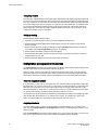
The figure below illustrates an example of device mapping to port groups. In the example, WWNs 1, 2,
and 3 can connect to any N_Port in Port Group 1 (PG1), while WWNs 4 and 5 can connect with any
N_Port in Port Group 2 (PG2).
38
Access Gateway Administrator's Guide
53-1003126-02
Configuring Ports in Access Gateway Mode
FIGURE 6 Example of device mapping to N_Port groups
The figure below shows an example of device mapping to specific N_Ports. Note that you can map one
or multiple WWNs to one N_Port to allow multiple devices to log in through one N_Port.
Access Gateway Administrator's Guide
53-1003126-02
39
Static versus dynamic mapping
FIGURE 7 Example device mapping to an N_Port
Static versus dynamic mapping
Device mapping can be classified as either "static" or "dynamic" as follows:
40
Access Gateway Administrator's Guide
53-1003126-02
Device mapping to port groups (recommended)
• Device mapping to an N_Port and to an N_Port group are considered static. Static mappings persists
across reboots and can be saved and restored with Fabric OS configUpload and configDownload
commands.
• Automatic Device Load Balancing, if enabled, is considered dynamic. These mappings exist only
while a device is logged in. Dynamic mappings cannot be saved or edited by the administrator and
do not persist across reboots. Dynamic mapping shows the current mapping for devices as opposed
to the original static mapping. If a device is mapped to an N_Port group, then all mapping is dynamic.
NOTE
Static and dynamic mapping only applies to NPIV devices and cannot redirect devices that are directly
attached to Access Gateway because physically-attached devices use the port maps to connect to the
fabric.
Device mapping to port groups (recommended)
Mapping NPIV devices to a port group is an ideal choice when a reasonably sized set of devices must
connect to the same group of N_Ports, and you want the flexibility of moving the devices to any
available F_Port. This type of mapping is recommended because the device will automatically connect
to the least-loaded N_Port in the group if the N_Port to which the device is currently connected goes
offline or is not yet online. For more information on port groups, refer to Port Grouping policy on page
56.
Use the following steps to map one or more devices to an N_Port group or remove device mapping
from an N_Port group.
1. Connect to the switch and log in using an account assigned to the admin role.
2. To add one or multiple device WWNs to an N_Port group , enter the ag --addwwnpgmapping
Port_Group command with the [WWN];[WWN] option.
All the listed device WWNs will use the least-loaded N_Port in the port group when they log in, unless
a specific device mapping can be used instead. This command can only map devices currently
connecting through NPIV.
The following example adds two devices to port group 3.
ag --addwwnpgmapping 3 "10:00:00:06:2b:0f:71:0c;10:00:00:05:1e:5e:2c:11"
3. To change all currently existing device mappings to a different port group, use the -- all option
instead of listing all the WWNs.
The following example changes all the currently mapped devices to use port group 3 instead of the
current port group mappings.
ag --addwwnpgmapping 3 --all
4. To remove one or multiple devices to an N_Port group , enter the ag --delwwnpgmapping
Port_Group command with the [WWN];[WWN] option.
All the listed devices will stop using the least-loaded N_Port in the group when they log in.
The following example removes mapping for two devices from port group 3.
ag --delwwnpgmapping 3 "10:00:00:06:2b:0f:71:0c;10:00:00:05:1e:5e:2c:11"
5. To remove all devices mapped to an N_Port group, enter the command with the --all option instead
of listing all WWNs. All of the devices will cease automatic use of the least-loaded port in the port
group when they log in. The --all option is a shortcut for specifying all of the devices that are already
mapped with the addwwnpgmapping command.
Access Gateway Administrator's Guide
53-1003126-02
41
Device mapping to N_Ports
The following example removes all devices mapped to port group 3.
ag --delwwnpgmapping 3 --all
6. Enter the ag --wwnmapshow command to display the list of WWNs mapped to port groups and
verify that the correct devices have been mapped to the desired port group.
Device mapping to N_Ports
Use the following steps to add one or more devices to an N_Port to route all device traffic to and from
the device through the specified N_Port. Also use these steps to remove device mapping to an
N_Port.
1. Connect to the switch and log in using an account assigned to the admin role.
2. To add one or multiple devices to an N_Port , enter the ag --addwwnmapping N_Port command
with the [WWN];[WWN] option. All the listed device WWNs will use the N_Port if it is available.
The following example adds two devices to N_Port 17.
ag --addwwnmapping 17 "10:00:00:06:2b:0f:71:0c;10:00:00:05:1e:5e:2c:11"
The --all option edits all the currently existing mappings. None of the --all options have any way to
detect what devices are using the switch. This option edits the mappings that are in the list.
3. To change all current device mappings to a different N_Port, enter the ag --addwwnmapping
N_Port command with the --all option.
The following command changes all the existing device mappings to use port 17.
ag --addwwnmapping 17 --all
4. To remove mapping for one or multiple devices from an N_Port, enter the ag --delwwnmapping
N_Port command with the [WWN];[WWN] option. All the listed device WWNs will no longer try to
use the N_Port unless a device logs in through an F_Port that is mapped to the N_Port.
The following example removes two devices from N_Port 17.
ag --delwwnmapping 17 "10:00:00:06:2b:0f:71:0c;10:00:00:05:1e:5e:2c:11"
5. To remove all devices currently mapped from an N_Port, enter the ag --delwwnmapping N_Port
command with the --all option. All the listed devices will no longer try to use the N_Port unless a
device logs in through an F_Port that is mapped to the N_Port. The --all option is a shortcut for
specifying all of the devices that are already mapped with the addwwnmapping command.
The following command removes all devices currently mapped to port 17.
ag --delwwnmapping 17 --all
6. Enter the ag --wwnmapshow command to display the list of N_Ports mapped to WWNs and verify
that the correct WWNs have been mapped or removed from the desired N_Ports.
Disabling device mapping
Use the following procedures to disable device mapping for all or only specific devices. These
procedures are useful when you want to temporarily disable device mapping, and then enable this at a
later time without reconfiguring your original mapping.
1. Connect to the switch and log in using an account assigned to the admin role.
2. Enter the ag --wwnmappingdisable command with the [WWN]; [WWN] option to disable mapping
for specific WWNs. The device mappings will be ignored for all the listed device WWNs without
removing the entry from the WWN mapping database.
42
Access Gateway Administrator's Guide
53-1003126-02
Enabling device mapping
The following example disables device mapping for two WWNs.
switch:admin> ag --wwnmappingdisable "10:00:00:06:2b:0f:71:0c; 10:00:00:05:1e:5e:
2c:11"
3. Enter the ag--wwnmappingdisable command with the --all option to disable mapping for all
available WWNs. The --all option will not affect mappings made in the future. Disabled mappings can
be modified without automatically enabling them.
The following example removes device mapping for all available WWNs.
switch:admin> ag --wwnmappingdisable --all
Enabling device mapping
Use the following steps to enable device mapping for all or specific devices that were previously
disabled.
1. Connect to the switch and log in using an account assigned to the admin role.
2. Enter the ag --wwnmappingenable command with the [WWN]; [WWN] option to enable mapping for
specific WWNs.
The following example enables two device WWNs.
switch:admin> ag --wwnmappingenable "10:00:00:06:2b:0f:71:0c; 10:00:00:05:1e:5e:2c:
11"
3. Enter the ag --wwnmappingenable command with the --all option to enable mapping for all currently
available WWNs. The --all option will not affect mappings made in the future. Any mapping added for
a new device (a device for which mapping is not disabled) will be enabled by default. Disabled
mappings can be modified without automatically enabling them.
The following command enables all previously disabled device mappings.
switch:admin> ag --wwnmappingenable --all
Displaying device mapping information
The ag --wwnmapshow command displays static and dynamic mapping information about all device
WWNs that have been mapped to N_Ports or N_Port groups. For each WWN, this command displays
the following:
•
•
•
•
•
•
WWN - Device WWNs that are mapped to N_Ports
1st N_Port - First or primary mapped N_Port (optional)
2nd N_Port - Secondary or failover N_Port (optional)
PG_ID - Port Group ID where the device is mapped
Current - The N_Port that the device is using (none displays if the device is not logged in)
Enabled - Indicates whether device mapping is enabled or disabled
Note that new device mappings will only be enabled and display the next time the device logs in to the
switch.
To display device mapping information, enter the ag -- wwnmapshow command.
Pre-provisioning
You can use Fabric OS commands, Web Tools, and Fabric Manager to map devices that do not yet
exist. This allows applicable management programs to push configuration changes without worrying
about the order in which they are received. For example, if system administrators need to push a set of
port group changes and a set of device mapping changes, they could push them in either order without
Access Gateway Administrator's Guide
53-1003126-02
43
VMware configuration considerations
error. This also applies to using Fabric OS commands for device mapping. You could also map
several devices to a new port group and then create the group without error. You can also remove one
device, and then remove another device without error.
VMware configuration considerations
Enabling device mapping for individual virtual machines (VMs) running on a VMware ESX server
connected to an F_Port can redirect I/O traffic for these VMs, provided the server is configured to use
Raw Device Mapped storage. All traffic will originate from a VM’s WWN and will follow any mapping
configured for the WWN. If anything interrupts the virtual port’s connection for the VM, such as a
failover port being used because a port goes offline, traffic will originate from the ESX server’s base
device port ID and not the VM’s port ID. If there are any additional disruptions, the server will not
switch back to the virtual port, and the VM’s traffic will not follow the configured device mapping. Note
that this can also occur when a VM first boots, prior to any failover.
When this behavior occurs, the VM’s WWN will be properly logged in to the fabric. The WWN appears
in the output of ag --show and ag --wwnmapshow , as well as on the switch. The output from the
portperfshow command displays all traffic on the port to which the ESX server port is mapped (base
PID).
Configuring device mapping
To configure WWN mapping on VMware ESX systems, use the following steps.
1. Make sure that virtual world wide port names (VWWPN) of virtual machines (VMs) are mapped to
the correct port group (or N_Port). Map all VWWPNs to N_Ports to avoid confusion.
2. Make sure all VWWPNs are mapped for LUN access for array-based targets.
3. Make sure to include all VWWPNs in the zone configuration.
4. Reboot the VM.
5. Zone the server’s physical port to the storage device.
6. Check the traffic that originates from the virtual node PID (VN PID). If the configuration is correct,
traffic will flow from the VN PID.
For additional information on using device mapping for connecting VMware systems, refer to the
Technical Brief How to Configure NPIV on VMware ESX Server 3.5 :
http://www.brocade.com/downloads/documents/brocade_vmware_technical_briefs/
Brocade_NPIV_ESX3.5_WP.pdf.
Failover and failback considerations
When using device mapping with VMware, the base device initiates PLOGI and PRLI to the target,
and then discovers the LUN. The virtual device also initiates a PLOGI and PRLI to the target, but LUN
discovery does not occur. Therefore, when the device-mapped port is toggled and failover or failback
takes place, traffic will resume from the base device. One of the following actions is recommended
when using device mapping with VMware:
• Make sure targets can be reached by the base device so that I/Os can resume if the mapped device
fails over and I/Os move over to the base PID.
• Reboot the server so that it initializes and uses configured device mapping.
Considerations for Access Gateway mapping
This section outlines considerations and limitations for Access Gateway mapping types.
44
Access Gateway Administrator's Guide
53-1003126-02
Mapping priority
Mapping priority
To avoid potential problems when both port and device mapping are implemented, AG uses the
following priority system when verifying policies to select the N_Port where a fabric login (FLOGI) is
routed. Access Gateway considers all available mappings in the following order until one can be used.
NOTE
Only NPIV devices can use device mapping and the automatic Device Load Balancing policy. Device
Load Balancing policy is enabled per module rather than per port group.
For more information, refer to Port Grouping policy on page 56.
1. Static device mapping to N_Port (if defined)
2. Device mapping to N_Port group (if defined)
3. Automatic Device Load Balancing within a port group (if enabled)
4. Port mapping to an N_Port
5. Port mapping to an N_Port in a port group (if defined)
Device mapping considerations
Consider the following points when using device mapping:
• If the N_Port is disabled, all devices that are mapped to it will be disabled. Depending on the
effective failover policy, the devices will be enabled on other N_Ports.
• Similar to port mappings, device mappings are affected by changes to underlying F_Ports. In other
words, if an F_Port needs to be taken offline, both the physical device and all virtual nodes behind it
will momentarily go offline.
• Once devices are mapped to an N_Port rather than an N_Port group, they cannot be automatically
rebalanced to another N_Port if an additional N_Port comes online.
• There can be cases where two NPIV devices logging in through the same F_Port are mapped to two
different N_Ports that are connected to two different fabrics. In this case, both NPIV devices may be
allocated the same PID by their respective fabrics. Once Access Gateway detects this condition, it
will disable that F_Port, and the event will be logged.
NOTE
Access Gateway algorithms reduce the chances of PID collisions, but they cannot be totally eliminated.
In some cases, you may be able to configure your virtual or physical fabrics to further reduce PID
collisions.
• Device mapping is not supported when firmware is downgraded to Fabric OS v6.3.x or earlier. You
must delete device mappings before downgrading or disable Device Load Balancing.
• Static and dynamic device mapping are only supported on the edge module in a cascaded Access
Gateway configuration.
• When mapping devices to a port group, make sure that all ports in the group have the same NPIV
login limit. If some ports have a lower login limit than the other ports, and there are many logins to the
group, some devices will repeatedly attempt to connect to the device with the lower limit (because it
has the fewest logins) and fail to connect.
Access Gateway Administrator's Guide
53-1003126-02
45
N_Port configurations
N_Port configurations
By default, on embedded switches, only the internal ports of Access Gateway are configured as
F_Ports. All external ports are configured (locked) as N_Ports. On standalone switches with AG
support, a preset number of ports are locked as N_Ports, and the rest of the ports operate as standard
F_Ports. Although some ports are locked as N_Ports, these ports can be converted to F_Ports. For
example, the figure below shows a host connected to external ports of an embedded switch with the
switch in AG mode. To convert an N_Port to an F_Port, first remove all the F_Ports that are mapped to
that N_Port, then unlock the port from N_Port state. Finally, define a map for the port. It is highly
recommended that all F_Ports mapped to the N_Port first be remapped to other N_Ports before
converting the N_Port to an F_Port. Also note that if the Automatic Port Configuration (APC) policy is
enabled, the port conversion is done automatically and no user intervention is necessary. For more
information on which ports are locked as N_Ports by default, see Table 7 on page 31.
FIGURE 8 Example of adding an external F_Port (F9) on an embedded switch
NOTE
A switch in Access Gateway mode must have at least one port configured as an N_Port. Therefore,
the maximum number of F_Ports that can be mapped to an N_Port is the number of ports on the
switch minus one.
46
Access Gateway Administrator's Guide
53-1003126-02
Displaying N_Port configurations
Displaying N_Port configurations
Use the following steps to determine which ports on a switch are locked as N_Ports.
1. Connect to the switch and log in using an account assigned to the admin role.
2. Enter the portcfgnport command. Command output will display "ON" for locked N_Ports.
Unlocking N_Ports
By default, on embedded switches, all external ports are configured in N_Port lock mode when you
enable Access Gateway. Access Gateway connects only FCP initiators and targets to the fabric. It does
not support other types of ports, such as ISL (interswitch link) ports.
By default, on fabric switches, the port types are not locked. Fabric OS Native mode dynamically
assigns the port type based on the connected device: F_Ports and FL_Ports for hosts, HBAs, and
storage devices; and E_Ports, EX_Ports, and VE_Ports for connections to other switches.
Unlocking the N_Port configuration automatically changes the port to an F_Port. When you unlock an
N_Port, the F_Ports are automatically unmapped and disabled.
Following are procedures for unlocking N_Ports that are in locked mode.
1. Connect to the switch and log in using an account assigned to the admin role.
2. Enter the portcfgnport command to display which ports on the switch are locked as N_Ports.
Command output will display "ON" for locked N_Ports.
NOTE
The portcfgnport command only works when the Port Grouping policy is enabled.
3. Enter the portcfgnport command and specify the port number and 0 (zero) to unlock N_Port mode.
switch:admin> portcfgnport 10 0
Alternatively, to lock a port in N_Port mode, enter the portcfgnport and specify the port number and
1.
switch:admin> portcfgnport 10 1
Persisting port online state
Initiate the portcfgpersisentenable command on all external or outward facing ports to ensure that
these ports come back online after a switch reboot or power failure. For an embedded switch, execute
this command through the chassis management console and not the switch CLI or the command may
not persist.
If the port is connected to another switch when this command is issued, the fabric may reconfigure.
After the port is persistently enabled, devices connected to the port can again communicate with the
fabric. Identify a single port to be configured by its port number or by its port index number. Port ranges
are supported with index numbers or by specifying a slot or a slot range. Issue the switchShow
command for a list of valid ports, slots, and port index numbers.
As an example, to persistently enable a port or range of ports, enter the following:
portcfgpersistentenable [slot
/]port1
[-port2
] [...]
Access Gateway Administrator's Guide
53-1003126-02
47
D_Port support
D_Port support
The Diagnostic (D_Port) feature is supported on 16-Gbps ports in the following configurations:
• An AG switch connected to an AG switch in cascaded configuration (supports only static D_Port).
• An AG switch connected to a Brocade fabric switch (supports only static D_Port).
• An AG switch connected to a Brocade HBA (supports static D_Port starting with Fabric OS 7.2.0;
dynamic D_Port starting with Fabric OS 7.3.0 and HBA v3.2.0).
The following types of D_Ports are supported:
• Static D_Port -- You can convert a Fibre Channel port into a D_Port on an AG switch, Brocade
HBA, fabric switch, or another AG switch (cascaded configuration) to test the link between the ports.
When you configure the ports on each end of the link as a D_Port, diagnostic tests automatically
initiate on the link when the D_Ports go online. Once in D_Port mode, the port does not participate
in fabric operations, log in to a remote device, or run data traffic. Comparison of Access Gateway
ports to standard switch ports on page 24 illustrates the supported D_Port configurations.
• Dynamic D_Port-- An AG switch supports dynamic D_Port mode starting with Fabric OS 7.3.0. If
the port on the connected Brocade HBA v3.2.0 is configured as a static D_Port, the AG port
automatically goes into D_Port mode. Once the AG port goes into dynamic D_Port mode, the switch
runs all the diagnostic tests automatically from the AG switch to connected HBA. Once the tests are
complete, the AG port will automatically revert back to an F_Port mode, if the HBA or device port
reverts back to be a normal port. However, dynamic D_Port mode is not supported in AG-to-AG and
AG-to-Switch connections; you need to configure and remove the D_Port statically in these cases.
To enable dynamic D_Port support on the AG switch, you can use the following switch-wide
configuration option available in the configure command:
Dynamic D-Port (on, off): [on] on
By default, the dynamic D_Port is on (enabled).
NOTE
N_Port-to-F_Port mappings must be removed from an AG F_Port before configuring it as a D_Port.
Refer to Saving port mappings on page 49.
Results from D_Port testing can be viewed using Fabric OS commands, such as portDPortTest -show, during or after testing. The adapter, fabric switch, or AG switch will be the initiator and the other
will be the responder. You can view detailed results from the initiator.
The following tests automatically run on the link between configured D_Ports:
•
•
•
•
Electrical loopback in SFP
Optical loopback in SFP
Link traffic test to test frame flow to ASIC or CPU
Link latency and distance measurement
For details on configuring D_Ports, using D_Ports, and D_Port limitations and considerations, refer to
the Fabric OS Administrator's Guide. For details on D_Port-related commands, refer to the Fabric OS
Command Reference.
Limitations and considerations
Following are specific limitations and considerations for using D_Ports in AG switch configurations. For
a complete list of D_Port limitations and considerations, refer to the Fabric OS Administrator's Guide.
48
Access Gateway Administrator's Guide
53-1003126-02
Saving port mappings
• D__Port must be configured on the AG, fabric switch, cascaded AG switch, or HBA before enabling
D_Ports on both sides of the link. Otherwise, the port will be persistently disabled.
• After configuring D_Port for an AG switch port, mapping will be not be retained. Static D_Port
configuration cannot be made unless mappings are removed from the port. This includes F_Port-toN_Port, static, preferred, and device (WWN) mapping. Therefore, all mappings must be manually
removed on the Access Gateway port before configuring the port as a D_Port.
Saving port mappings
Before configuring static D_Ports, you must remove all mappings between the subject ports and
devices as they will not be retained. This includes port (N_Port-to-F_Port), device (WWN), static, and
dynamic mapping. You can save N_Port mappings using Fabric OS commands. Once you save the
mappings, you can display them so that you can manually reconfigure them after the D_Port is
disabled. A command is also available to delete saved N_Port mappings. The following are available
backup mapping commands. For more details, refer to the Fabric OS Command Reference .
• To save configured N_Port mappings, enter the following command:
ag --backupmappingsave N_Port
• To display saved N__Port mappings so that you can reconfigure them on the switch, enter the
following command:
ag --backupmappingshow N_Port
Following is an example of command output:
sw0:root>ag --backupmappingshow 44
Configured static and prefered mappings haved been saved for the N_port
successfully
N_Port
44
Backed-up Configured F_Ports
20:21:22
Backed-up Static F_Ports
23:24
Backed-up Preferred F_Ports
26:27:28:29
• To delete configured N_Port mappings, enter the following command:
ag --backupmappingdel N_Port
Access Gateway Administrator's Guide
53-1003126-02
49
Saving port mappings
50
Access Gateway Administrator's Guide
53-1003126-02
Managing Policies and Features in Access Gateway Mode
● Access Gateway policies overview................................................................................. 51
● Advanced Device Security policy ................................................................................... 52
● Automatic Port Configuration policy ............................................................................... 55
● Port Grouping policy........................................................................................................56
● Device Load Balancing policy......................................................................................... 62
● Persistent ALPA policy....................................................................................................63
● Failover policy................................................................................................................. 65
● Failback policy.................................................................................................................71
● Trunking in Access Gateway mode.................................................................................75
● Adaptive Networking on Access Gateway...................................................................... 82
● Per-Port NPIV login limit................................................................................................. 84
● Duplicate PWWN handling during device login...............................................................84
● Performance Monitoring..................................................................................................85
● Considerations for the Brocade 6505 and 6510..............................................................88
Access Gateway policies overview
This chapter provides detailed information on all Access Gateway policies. These policies can be used
to control various advanced features, such as failover, failback, and trunking, when used in Access
Gateway mode.
Displaying current policies
You can run the following command to display policies that are currently enabled or disabled on a
switch.
1. Connect to the switch and log in using an account assigned to the admin role.
2. Enter the ag --policyshow command.
Access Gateway policy enforcement matrix
The table below shows which policies can be enabled at the same time. For example, in the Auto Port
Configuration policy row, only N_Port Trunking and Advanced Device Security can be enabled with this
policy.
TABLE 8 Policy enforcement matrix
Policies
Auto Port
Configuration
N_Port Grouping N_Port Trunking Advanced Device
Security
Auto Port Configuration
N/A
No
Access Gateway Administrator's Guide
53-1003126-02
Yes
Yes
51
Advanced Device Security policy
TABLE 8 Policy enforcement matrix (Continued)
Policies
Auto Port
Configuration
N_Port Grouping N_Port Trunking Advanced Device
Security
N_Port Grouping
Mutually exclusive
N/A
Yes
Yes
N_Port Trunking
Yes
Yes
N/A
Yes
Advanced Device Security Yes
Yes
Yes
N/A
Device Load Balancing
Yes
Yes
Yes
No
Advanced Device Security policy
Advanced Device Security (ADS) is a security policy that restricts access to the fabric at the AG level
to a set of authorized devices. Unauthorized access is rejected and the system logs a RASLOG
message. You can configure the list of allowed devices for each F_Port by specifying their Port WWN
(PWWN). The ADS policy secures virtual and physical connections to the SAN.
How the ADS policy works
When you enable the ADS policy, it applies to all F_Ports on the AG-enabled module. By default, all
devices have access to the fabric on all ports. You can restrict the fabric connectivity to a particular set
of devices where AG maintains a per-port allow list for the set of devices whose PWWN you define to
log in through an F_Port. You can view the devices with active connections to an F_Port using the ag
--show command.
NOTE
The ag --show command only displays F_Ports on Core AGs, such as the AGs that are directly
connected to fabric. Use the agshow --name command on the fabric switch to display the F_Ports of
both the Core and Edge AGs.
Alternatively, the security policy can be established in the Enterprise fabric using the Device
Connection Control (DCC) policy. For information on configuring the DCC policy, refer to Enabling the
DCC policy on a trunk on page 77. The DCC policy in the Enterprise fabric takes precedence over
the ADS policy. It is generally recommended to implement the security policy in the AG module rather
than in the main fabric, especially if the Failover and Failback policies are enabled.
Enabling and disabling the ADS policy
By default, the ADS policy is disabled. When you manually disable the ADS policy, all of the allow lists
(global and per-port) are cleared. Before disabling the ADS policy, you should save the configuration
using the configUpload command in case you need this configuration again.
4
5
52
The ADS policy is not supported when using device mapping.
Device Load Balancing and Automatic Login Balancing cannot be enabled for the same port group.
Access Gateway Administrator's Guide
53-1003126-02
Allow lists
1. Connect to the switch and log in using an account assigned to the admin role.
2. Enter the ag --policyenable ads command to enable the ADS policy.
switch:admin> ag --policyenable ads
The policy ADS is enabled
3. Enter the ag - - policydisable ads command to disable the ADS policy.
switch:admin> ag --policydisable ads
The policy ADS is disabled
NOTE
Use the ag --policyshow command to determine the current status of the ADS policy.
Allow lists
You can determine which devices are allowed to log in on a per-F_Port basis by specifying lists of
F_Ports and device WWNs in the ag --adsset command. The ADS policy must be enabled for this
command to succeed.
ag --adsset "F_Port [ ;F_Port2;... ] " " WWN [ ;WWN2;... ]"
Lists must be enclosed in quotation marks. List members must be separated by semicolons. The
maximum number of entries in the allowed device list is twice the per-port maximum login count.
Use an asterisk (*) instead of port numbers in the F_Port list to add the specified WWNs to all the
F_Ports allow lists. Use an asterisk (*) instead of WWNs to indicate access to all devices from the
specified F_Port list. A blank WWN list ("") indicates no access.
NOTE
Use an asterisk enclosed in quotation marks ("*") to set the allow list to "all access"; use a pair of double
quotation marks ("") to set the allow list to "no access".
Note the following characteristics of the allow list:
•
•
•
•
The maximum device entries allowed in the allow list is twice the per-port maximum login count.
Each port can be configured to "not allow any device" or "to allow all the devices" to log in.
If the ADS policy is enabled, by default, every port is configured to allow all devices to log in.
The same allow list can be specified for more than one F_Port.
Setting the list of devices allowed to log in
1. Connect to the switch and log in using an account assigned to the admin role.
2. Enter the ag --adsset command with the appropriate options to set the list of devices allowed to log
in to specific ports. In the following example, ports 1, 10, and, 13 are set to "all access."
switch:admin> ag --adsset
"1;10;13" "*"
WWN list set successfully as the Allow Lists of the F_Port[s]
Access Gateway Administrator's Guide
53-1003126-02
53
Setting the list of devices not allowed to log in
Setting the list of devices not allowed to log in
1. Connect to the switch and log in using an account assigned to the admin role.
2. Enter the ag --adsset command with the appropriate options to set the list of devices not allowed to
log in to specific ports. In the following example, ports 11 and 12 are set to "no access."
switch:admin > ag --adsset
"11;12" ""
WWN list set successfully as the Allow Lists of the F_Port[s]
Removing devices from the list of allowed devices
Remove specified WWNs from the list of devices allowed to log in to the specified F_Ports using the
ag --adsdel command.
ag--adsdel " F_Port [; F_Port2; ...] " " WWN [ ;WWN2;.. .] "
For more details on this command and its operands, refer to the Fabric OS Command Reference
Manual .
Lists must be enclosed in quotation marks. List members must be separated by semicolons. Replace
the F_Port list with an asterisk (*) to remove the specified WWNs from all the F_Ports allow lists. The
ADS policy must be enabled for this command to succeed.
1. Connect to the switch and log in using an account assigned to the admin role.
2. Enter the ag--adsdel command to remove one or more devices from the list of allowed devices.
In the following example, two devices are removed from the list of allowed devices (ports 3 and 9).
switch:admin> ag --adsdel
"3;9"
"22:03:08:00:88:35:a0:12;22:00:00:e0:8b:88:01:8b"
WWNs removed successfully from Allow Lists of the F_Port[s]Viewing F_Ports
allowed to login
Adding new devices to the list of allowed devices
Add specified WWNs to the list of devices allowed to log in to the specified F_Ports using the ag -adsadd command.
ag--adsadd " F_Port [;F_Port2;...] " " WWN [;WWN2;...] "
For more details on this command and its operands, refer to the Fabric OS Command Reference
Manual .
Lists must be enclosed in quotation marks. List members must be separated by semicolons. Replace
the F_Port list with an asterisk (*) to add the specified WWNs to all the F_Ports allow lists. The ADS
policy must be enabled for this command to succeed.
1. Connect to the switch and log in using an account assigned to the admin role.
2. Enter the ag --adsadd command with the appropriate options to add one or more new devices to
the list of allowed devices.
In the following example, two devices are added to the list of allowed devices (for ports 3 and 9).
switch:admin> ag --adsadd "3;9"
"20:03:08:00:88:35:a0:12;21:00:00:e0:8b:88:01:8b"
WWNs added successfully to Allow Lists of the F_Port[s]
54
Access Gateway Administrator's Guide
53-1003126-02
Displaying the list of allowed devices on the switch
Displaying the list of allowed devices on the switch
1. Connect to the switch and log in using an account assigned to the admin role.
2. Enter the ag --adsshow command.
For each F_Port, command output will show access for all devices, a list of device WWNs, or no
access. For more details on this command and its output, refer to the Fabric OS Command
Reference Manual .
ADS policy considerations
The following are considerations for setting the ADS policy:
• In cascading configurations, you should set the ADS policy on the AG module that directly connects
to the servers.
• The ADS policy can be enabled or disabled independent of the status of other AG policies.
• The ADS policy is not supported with device mapping.
Upgrade and downgrade considerations for the ADS policy
Downgrading to Fabric OS v6.4.0 or earlier is supported.
Downgrading from Fabric OS v7.1.0 to v6.4.0 or upgrading from Fabric OS v6.4.0 to v7.1.0 will not
change the ADS policy settings.
Automatic Port Configuration policy
The Automatic Port Configuration (APC) provides the ability to automatically discover port types (host,
target, or fabric) and dynamically update the port maps when a change in port-type connection is
detected. This policy is intended for a fully hands-off operation of Access Gateway. APC dynamically
maps F_Ports across available N_Ports so they are evenly distributed.
How the APC policy works
When the APC policy is enabled and a port on AG is connected to a Fabric switch, AG configures the
port as an N_Port. If a host is connected to a port on AG, then AG configures the port as an F_Port and
automatically maps it to an existing N_Port with the least number of F_Ports mapped to it. When the
APC policy is enabled, it applies to all ports on the switch.
Enabling and disabling the APC policy
Use the following steps to enable and disable Automatic Port Configuration policy. This policy is
disabled by default in Access Gateway.
Enabling the APC policy
1. Connect to the switch and log in using an account assigned to the admin role.
2. Enter the switchDisable command to ensure that the switch is disabled.
Access Gateway Administrator's Guide
53-1003126-02
55
Disabling the APC policy
3. Enter the configUpload command to save the switch’s current configuration.
4. Enter the ag --policydisable pg command to disable the Port Grouping (PG) policy.
5. Enter the ag --policyenable auto command to enable the APC policy.
6. At the command prompt, type Y to enable the policy.
The switch is ready; a reboot is not required.
Disabling the APC policy
1. Connect to the switch and log in using an account assigned to the admin role.
2. Enter the switchDisable command to ensure that the switch is disabled.
3. Enter the configUpload command to save the switch’s current configuration.
4. Enter the ag --policyDisable auto command to disable the APC policy.
5. At the command prompt, type Y to disable the policy.
6. Enter the switchEnable command to enable the switch.
APC policy considerations
Following are the considerations for the Automatic Port Configuration (APC) policy:
• The APC and the PG policies cannot be enabled at the same time. You can still benefit from the
automatic port mapping feature of the APC policy when the Port Grouping policy is enabled by
enabling the auto distribution feature for each port group.
• You cannot manually configure port mapping when the APC policy is enabled.
• The APC policy applies to all ports on the switch. Enabling the APC policy is disruptive and erases
all existing port mappings. Therefore, before enabling the APC policy, you should disable the AG
module. When you disable the APC policy, the N_Port configuration and the port mapping revert
back to the default factory configurations for that platform. It is recommended that before you either
disable or enable APC policy, you save the current configuration file using the configUpload
command in case you need this configuration again.
Upgrade and downgrade considerations for the APC policy
You can downgrade to a Fabric OS level that supports the APC policy. You can upgrade from Fabric
OS v6.4.0 to Fabric OS v7.1.0, and the policy that was enabled in Fabric OS v6.4.0 will be maintained.
Upgrade to Fabric OS v7.1.0 from Fabric OS releases prior to v6.4.0 is not supported.
Port Grouping policy
Use the Port Grouping (PG) policy to partition the fabric, host, or target ports within an AG-enabled
module into independently operated groups. Use the PG policy in the following situations:
• When connecting the AG module to multiple physical or virtual fabrics.
• When you want to isolate specific hosts to specific fabric ports for performance, security, or other
reasons.
56
Access Gateway Administrator's Guide
53-1003126-02
How port groups work
How port groups work
Create port groups using the ag --pgcreate command. This command groups N_Ports together as "port
groups." By default, any F_Ports mapped to the N_Ports belonging to a port group will become
members of that port group. Port grouping fundamentally restricts failover of F_Ports to the N_Ports that
belong to that group. For this reason, an N_Port cannot be member of two port groups. The default PG0
group contains all N_Ports that do not belong to any other port groups.
The figure below shows that if you have created port groups and then an N_Port goes offline, the
F_Ports being routed through that port will fail over to any of the N_Ports that are part of that port group
and are currently online. For example, if N_Port 4 goes offline, then F_Ports 7 and 8 are routed through
to N_Port 3 as long as N_Port 3 is online because both N_Ports 3 and 4 belong to the same port group,
PG2. If no active N_Ports are available, the F_Ports are disabled. The F_Ports belonging to a port
group do not fail over to N_Ports belonging to another port group.
FIGURE 9 Port grouping behavior
When a dual redundant fabric configuration is used, F_Ports connected to a switch in AG mode can
access the same target devices from both of the fabrics. In this case, you must group the N_Ports
connected to the redundant fabric into a single port group. It is recommended to have paths fail over to
the redundant fabric when the primary fabric goes down.
Access Gateway Administrator's Guide
53-1003126-02
57
Adding an N_Port to a port group
FIGURE 10 Port group 1 (PG1) setup
Adding an N_Port to a port group
1. Connect to the switch and log in using an account assigned to the admin role.
2. Enter the ag --pgadd command with the appropriate options to add an N_Port to a specific port
group. In the following example, N_Port 14 is added to port group 3.
Note that if you add more than one N_Port, you must separate them with a semicolon.
switch:admin> ag --pgadd 3 14
N_Port[s] are added to the port group 3
Deleting an N_Port from a port group
Before deleting an N_Port, all F_Ports mapped to the N_Port should be remapped before the N_Port
is deleted from a port group.
1. Connect to the switch and log in using an account assigned to the admin role.
2. Enter the ag --pgdel command with the appropriate options to delete an N_Port from a specific port
group. In the following example, N_Port 13 is removed from port group 3.
switch:admin> ag --pgdel 3 13
N_Port[s] are deleted from port group 3
3. Enter the ag --pgshow command to verify the N_Port was deleted from the specified port group.
Removing a port group
1. Connect to the switch and log in using an account assigned to the admin role.
2. Enter the ag --pgremove command with the appropriate options to remove a port group. In the
following example, port group 3 is removed.
switch:admin> ag --pgremove 3
58
Access Gateway Administrator's Guide
53-1003126-02
Renaming a port group
Renaming a port group
1. Connect to the switch and log in using an account assigned to the admin role.
2. Enter the ag --pgrename command with the appropriate options to rename a port group. In the
following example, port group 2 is renamed to MyEvenFabric.
switch:admin> ag --pgrename 2 MyEvenFabric
Port Group 2 has been renamed as MyEvenFabric successfully
Disabling the Port Grouping policy
The Port Grouping (PG) policy is enabled by default for Access Gateway. To disable this policy, use the
following steps.
1. Connect to the switch and log in using an account assigned to the admin role.
2. Enter the ag --policydisable pg command to disable the Port Grouping policy.
Port Grouping policy modes
You can enable and disable the Automatic Login Balancing and Managed Fabric Name Monitoring
(MFNM) Port Grouping policy modes when you create port groups using the pgcreate command.
Alternately, you can enable these modes using the ag --pgsetmodes command.
Automatic Login Balancing mode
If Automatic Login Balancing mode is enabled for a port group and an F_Port goes offline, logins in the
port group are redistributed among the remaining F_Ports. Similarly, if an N_Port comes online, port
logins in the port group are redistributed to maintain a balanced N_Port-to-F_Port ratio.
Consider the following notes about Automatic Login Balancing mode:
• Automatic Login Balancing mode is disruptive. However, you can minimize disruption by disabling or
enabling rebalancing of F_Ports on F_Port offline events or N_Port online events.
• You must explicitly enable Automatic Login Balancing on a port group.
• If an N_Port is deleted from a port group enabled for Automatic Login Balancing mode, the F_Ports
mapped to that N_Port stay with the port group as long as there are other N_Ports in the group. Only
the specified N_Port is removed from the port group. This is because the F_Ports are logically
associated with the port groups that are enabled for Automatic Login Balancing mode. This is not the
case for port groups not enabled for Automatic Login Balancing mode. When you delete an N_Port
from one of these port groups, the F_Ports that are mapped to the N_Port move to PG0 along with
the N_Port. This is because the F_Ports are logically associated with the N_Ports in port groups not
enabled for Automatic Login Balancing mode.
Managed Fabric Name Monitoring mode
When enabled, Managed Fabric Name Monitoring (MFNM) mode queries the fabric name at a specific
time period. If it detects an inconsistency, for example all the N_Ports within a port group are not
physically connected to the same physical or virtual fabric, it generates a RASLOG message. In
"default" mode, a message is logged into RASLOG. In "managed" mode, automatic failover is disabled
for all N_Ports within the N_Port group, and a message is logged into RASLOG about multiple fabrics.
Enable or disable MFNM mode on a port group using the steps under Enabling MFNM mode on page
61 and Disabling MFNM mode on page 61. In both default and managed mode, the system queries
the fabric name once every 120 seconds. You can configure the monitoring timeout value to something
Access Gateway Administrator's Guide
53-1003126-02
59
Creating a port group and enabling Automatic Login Balancing mode
other than 120 seconds using the steps under Setting the current MFNM mode timeout value on page
61.
Creating a port group and enabling Automatic Login Balancing mode
1. Connect to the switch and log in using an account assigned to the admin role.
2. Enter the ag --pgcreate command with the appropriate options to create a port group. In the
following example, a port group named "FirstFabric" is created that includes N_Ports 1 and 3 and
has Automatic Login Balancing (lb) enabled.
switch:admin> ag --pgcreate 3 "1;3" -n FirstFabric1 -m "lb"
Port Group 3 created successfully
3. Enter the ag --pgshow command to verify the port group was created. A table containing a port
group with ID 3 and ports 1 and 3 should display.
Rebalancing F_Ports
To minimize disruption that could occur once F_Ports go offline or when additional N_Ports are
brought online, you can modify the default behavior of Automatic Login Balancing mode by disabling
or enabling rebalancing of F_Ports when F_Port offline or N_Port online events occur.
1. Connect to the switch and log in using an account assigned to the admin role.
2. Enter the agautomapbalance --enable command with the appropriate options to enable automatic
login redistribution of F_Ports. In the following example, rebalancing of F_Ports in port group 1 in
Access Gateway is enabled when an F_Port online event occurs.
switch:admin> agautomapbalance --enable -fport -pg 1
3. Enter the agautomapbalance --disable - all command with the appropriate options to disable
automatic login distribution of N_Ports for all port groups in the Access Gateway when an N_Port
online event occurs.
switch:admin> agautomapbalance --disable -nport -all
4. Enter the agautomapbalance --disable - all command with the appropriate options to disable
automatic login distribution of F_Ports for all port groups in the Access Gateway when an F_Port
online event occurs.
switch:admin> agautomapbalance --disable -fport -all
5. Enter the agautomapbalance --show command to display the automatic login redistribution
settings for port groups. In the following example, there are two port groups, 0 and 1.
switch:admin> agautomapbalance --show
AG Policy: pg
-------------------------------------------PG_ID LB mode nport fport
-------------------------------------------0 Enabled
Enabled
1 Disabled
-
Disabled
-
This command also displays the automatic login redistribution settings for N_Ports and F_Ports. For
more details on this command and its output, refer to the Fabric OS Command Reference Manual .
Considerations when disabling Automatic Login Balancing mode
Consider the following when disabling Automatic Login Balancing mode:
60
Access Gateway Administrator's Guide
53-1003126-02
Enabling MFNM mode
• Be aware that modifying Automatic Login Balancing mode default settings using the
agautomapbalance command may yield uneven distribution of F_Ports to N_Ports. In such cases,
you might consider a manual login distribution that forces a rebalancing of F_Ports to N_Ports.
• To control automatic rebalancing to avoid disruptions when the Port Grouping policy is enabled, refer
to Rebalancing F_Ports on page 60.
Enabling MFNM mode
1. Connect to the switch and log in using an account assigned to the admin role.
2. Enter the ag --pgsetmodes command with the appropriate options to enable MFNM mode. This
command changes the monitoring mode from "default" to "managed." In the following example,
MFNM mode is enabled for port group 3.
switch:admin> ag --pgsetmodes 3 "mfnm"
Managed Fabric Name Monitoring mode has been enabled for Port Group 3
Disabling MFNM mode
1. Connect to the switch and log in using an account assigned to the admin role.
2. Enter the ag --pgdelmodes command with the appropriate options to disable MFNM mode. In the
following example, MFNM mode is disabled for port group 3.
switch:admin> ag --pgdelmodes 3 "mfnm"
Managed Fabric Name Monitoring mode has been disabled for Port Group 3
3. Enter the ag --pgshow command to display the port group configuration. If disabled, "mfnm" should
not display under PG_Mode for port 3.
For more details on this command and its operands, refer to the Fabric OS Command Reference
Manual .
Displaying the current MFNM mode timeout value
1. Connect to the switch and log in using an account assigned to the admin role.
2. Enter the ag --pgfnmtov command to display the current MFNM timeout value.
switch:admin> ag --pgfnmtov
Fabric Name Monitoring TOV: 120 seconds
Setting the current MFNM mode timeout value
1. Connect to the switch and log in using an account assigned to the admin role.
2. Enter the ag --pgfnmtov command, followed by a value in seconds.
switch:admin> ag --pgfnmtov 100
This sets the timeout value to 100 seconds.
Port Grouping policy considerations
Following are the considerations for the Port Grouping policy:
• A port cannot be a member of more than one port group.
• The PG policy is enabled by default in Fabric OS v6.0 and later. A default port group "0" (PG0) is
created, which contains all ports on the AG.
Access Gateway Administrator's Guide
53-1003126-02
61
Upgrade and downgrade considerations for the Port Grouping policy
• APC policy and PG policy are mutually exclusive. You cannot enable these policies at the same
time.
• If an N_Port is added to a port group or deleted from a port group and Automatic Login Balancing
mode is enabled or disabled for the port group, the N_Port maintains its original failover or failback
setting. If an N_Port is deleted from a port group, it automatically gets added to port group 0.
• When specifying a preferred secondary N_Port for a port group, the N_Port must be from the same
group. If you specify an N_Port as a preferred secondary N_Port and it already belongs to another
port group, the operation fails. Therefore, it is recommended to form groups before defining the
preferred secondary path.
• If the PG policy is disabled while a switch in AG mode is online, all the defined port groups are
deleted, but the port mapping remains unchanged. Before disabling the PG policy, you should save
the configuration using the configUpload command in case you might need this configuration
again.
• If N_Ports connected to unrelated fabrics are grouped together, N_Port failover within a port group
can cause the F_Ports to connect to a different fabric. The F_Ports may lose connectivity to the
targets to which they were connected before the failover, thus causing I/O disruption, as shown in
How port groups work on page 57. Ensure that the port group mode is set to MFNM mode (refer to
Enabling MFNM mode on page 61). This monitors the port group to detect connection to multiple
fabrics and disables failover of the N-ports in the port group. For more information on MFNM, refer
to Managed Fabric Name Monitoring mode on page 59.
Upgrade and downgrade considerations for the Port Grouping policy
Downgrading to Fabric OS v6.4.0 or earlier is supported.
Note the following considerations when upgrading to Fabric OS 7.1.0:
• When upgrading to Fabric OS v7.1.0 from v6.4.0, the PG policy that was enforced in Fabric OS
v6.4.0 continues to be enforced in Fabric OS v7.1.0 and the port groups are retained. You should
save the configuration file using the configUpload command in case you might need this
configuration again.
• Upgrade to Fabric OS v7.1.0 from Fabric OS prior to v6.4.0 is not supported.
Device Load Balancing policy
When the Device Load Balancing policy is enabled, devices mapped to a port group always log in to
the least-loaded N_Port in that port group. This helps to distribute the login load on each of the
N_Ports. This policy is intended for use in conjunction with device mapping. It provides an automatic
approach to mapping devices to the least-loaded N_Port within an N_Port group. To effectively use
this policy, it is recommended that you map devices to desired N_Port groups before enabling this
policy. The Port Grouping policy must be enabled before you can enable Device Load Balancing.
Manually created mappings from devices to N_Ports take precedence over automatically created
mappings. Refer to Mapping priority on page 45 for details on connection priority for AG port mapping.
For more information on device mapping, refer to Device mapping on page 37.
Enabling the Device Load Balancing policy
Use the following steps to enable Device Load Balancing.
1. Connect to the switch and log in using an account assigned to the admin role.
2. Enter the configUpload command to save the switch’s current configuration.
62
Access Gateway Administrator's Guide
53-1003126-02
Disabling the Device Load Balancing policy
3. The Port Grouping policy must be enabled to enable Device Load Balancing. Enter the ag -policyshow command to determine if the Port Grouping policy is enabled. If it is not enabled, enter
ag --policyenable pg to enable this policy.
4. Enter the ag --policyenable wwnloadbalance command to enable the Device Load Balancing
policy. Because Fibre Channel devices are identified by their WWNs, CLI commands use device
WWNs.
Disabling the Device Load Balancing policy
Before disabling this policy, you should save the configuration using the configUpload command in
case you need this configuration again.
1. Connect to the switch and log in using an account assigned to the admin role.
2. Enter the ag --policydisable wwnloadbalance command to disable the Device Load Balancing
policy.
3. Enter the ag --policyshow command to determine the current status of the Device Load Balancing
policy.
Device Load Balancing policy considerations
• The Device Load Balancing policy should be enabled on the edge AG of a cascaded AG
configuration.
• The Device Load Balancing policy is not applicable on a port group when the APC policy or
Automatic Login Balancing are enabled.
• If a device is mapped to a port that is currently part of a trunk, then the device will use that trunk.
When trunking is used with the Device Load Balancing policy, then the load on each trunk will be
proportional to the number of ports in that trunk. Use the ag -show command to determine the
devices using a particular trunk.
• When using the Device Load Balancing policy, make sure that all ports in the port group have the
same NPIV login limit. If some ports have a lower login limit than the other ports, and there are many
logins to the group, some devices will repeatedly attempt to connect to the device with the lower limit
(because it has the fewest logins) and fail to connect.
Persistent ALPA policy
The Persistent ALPA policy is meant for host systems with operating systems that cannot handle
different PID addresses across login sessions when booting over a SAN. The Persistent ALPA policy for
switches in Access Gateway mode allows you to configure the AG module so that the host is more likely
to get the same PID when it logs out of and into the same F_Port. Because the Arbitrated Port Loop
Address (ALPA) field makes up a portion of the PID, the PID may change across switch or server power
cycles. This policy, if enabled, helps reduce the chances of a different PID being issued for the same
host.
The benefit of this policy is that it ensures that a host has the same ALPA on the F_Ports through the
host power cycle. You can also achieve the same behavior and benefit by setting the same policy in the
main (core) fabric. When this policy is enabled, AG will request the same ALPA from the core fabric.
However, depending on the fabric, this request may be denied. When this occurs, the host is assigned a
different ALPA. The following modes deal with this situation:
Access Gateway Administrator's Guide
53-1003126-02
63
Enabling the Persistent ALPA policy
• In "Flexible" mode, the AG logs an event that it did not receive the same (requested) ALPA from the
core fabric and brings up the device with the ALPA assigned by the fabric.
• In the "Stringent" mode, if the requested ALPA is not available, the server login will be rejected and
the server port cannot log in to the fabric.
Enabling the Persistent ALPA policy
By default, Persistent ALPA is disabled. You can enable Persistent ALPA using the ag -persistentalpaenable command with the following syntax and with one of the following value types:
ag -persistentalpaenable 1/0[On/Off] -s/-f[Stringent/Flexible]
• Flexible ALPA assigns an unassigned ALPA value when the ALPA assigned to the device is taken
by another host.
• Stringent ALPA causes the host login request to be rejected by AG if assignment of the same ALPA
is not possible.
To enable Persistent ALPA, use the following steps.
1. Connect to the switch and log in using an account assigned to the admin role.
2. Enter the ag --persistentalpaenable command to enable persistent ALPA in flexible (-f ) or
stringent (-s ) mode. The following example shows enabling the policy in flexible mode.
switch:admin> ag --persistentalpaenable 1 -f
To ensure consistency among the different devices, after Persistent ALPA is enabled, all the ALPAs
become persistent, whether or not they were logged in before the Persistent ALPA policy was
enabled.
Disabling the Persistent ALPA policy
When you disable this policy, do not specify the value type (for example, flexible ALPA or stringent
ALPA). Use the following steps.
1. Connect to the switch and log in using an account assigned to the admin role.
2. Enter the ag --persistentalpadisable command.
switch:admin> ag --persistentalpaenable 0
Persistent ALPA device data
Access Gateway uses a table to maintain a list of available and used ALPAs. When the number of
entries in this table is exhausted, the host receives an error message. You can remove some of the
entries to make space using the instructions in Removing device data from the database on page
64.
Removing device data from the database
Use the following steps to remove device data from the database.
1. Connect to the switch and log in using an account assigned to the admin role.
2. Enter the ag --deletepwwnfromdb command.
switch:admin> ag --deletepwwnfromdb PWWN
64
Access Gateway Administrator's Guide
53-1003126-02
Displaying device data
In the example, PWWN is the port that you want to remove from the database.
Displaying device data
You can view the ALPA of the host related to any ports you delete from the database.
1. Connect to the switch and log in using an account assigned to the admin role.
2. Enter the ag --printalpamap command with the appropriate option to display a database entry for a
specific F_Port. The following example will display an entry for F_Port 2.
switch:admin> ag --printalpamap 2
Clearing ALPA values
You can clear the ALPA values for a specific port.
1. Connect to the switch and log in using an account assigned to the admin role.
2. Enter the ag --clearalpamap command with the appropriate option to remove the PWW-to-ALPA
mapping for a specific port. In the following example, the mapping for port 2 is cleared from the
database.
switch:admin> ag --clearalpamap 2
NOTE
All the device data must be persistent in case of a reboot. During a reboot, the tables will be dumped
to the persistent_NPIV_config file.
Persistent ALPA policy considerations
The Persistent ALPA policy is not supported in the following situations:
• When AG N_Ports are connected to the shared ports of 48-port Director blades.
• Cisco fabrics. Enable Persistent FCID mode on the connecting Cisco switch to achieve the same
functionality.
• Persistent ALPA configuration will not change to the default when the configDefault command is
used, but will retain the previous configuration.
Failover policy
The Access Gateway Failover policy ensures maximum uptime for the servers. When a port is
configured as an N_Port, the Failover policy is enabled by default and is enforced during power-up. The
Failover policy allows hosts and targets to automatically remap to another online N_Port if the primary
N-Port goes offline.
NOTE
For port mapping, the Failover policy must be enabled on an N_Port for failover to occur. For device
mapping, if a device is mapped to an N_Port in a port group, the device will always reconnect to the
least-loaded online N_Port in the group (or secondary N_Port in the group if configured) if the primary
Access Gateway Administrator's Guide
53-1003126-02
65
Failover with port mapping
N_Port goes offline. This occurs regardless of whether the Failover policy is enabled or disabled for
the primary N_Port.
Failover with port mapping
The Failover policy allows F_Ports to automatically remap to an online N_Port if the primary N_Port
goes offline. If multiple N_Ports are available for failover, the Failover policy evenly distributes the
F_Ports to available N_Ports belonging to the same N_Port group. If no other N_Port is available,
failover does not occur and the F_Ports mapped to the primary N_Port go offline as well.
AG provides an option to specify a secondary failover N_Port for an F_Port.
NOTE
If failover and failback policy are disabled, an F_Port mapped to an N_Port will go offline when the
N_Port goes offline and it will go online when the N_Port comes online.
Failover configurations in Access Gateway
The following sequence describes how a failover event occurs:
• An N_Port goes offline.
• All F_Ports mapped to that N_Port are temporarily disabled.
• If the Failover policy is enabled on an offline N_Port, the F_Ports mapped to it will be distributed
among available online N_Ports. If a secondary N_Port is defined for any of these F_Ports, these
F_Ports will be mapped to those N_Ports. If the Port Grouping policy is enabled, then the F_Ports
only fail over to N_Ports that belong to the same port group as the originally offline N_Port.
Failover example
The following example shows the failover sequence of events in a scenario where two fabric ports go
offline, one after the other. Note that this example assumes that no preferred secondary N_Port is set
for any of the F_Ports.
• First, the Edge switch F_A1 port goes offline, as shown in Example 1 below, causing the
corresponding Access Gateway N_1 port to be disabled.
The ports mapped to N_1 fail over; F_1 fails over to N_2 and F_2 fails over to N_3.
• Next, the F_A2 port goes offline, as shown in Example 2 below, causing the corresponding Access
Gateway N_2 port to be disabled.
The ports mapped to N_2 (F_1, F_3, and F_4) fail over to N_3 and N_4. Note that the F_Ports are
evenly distributed to the remaining online N_Ports and that the F_2 port did not participate in the
failover event.
66
Access Gateway Administrator's Guide
53-1003126-02
Managing Policies and Features in Access Gateway Mode
FIGURE 11 Failover behavior
Access Gateway Administrator's Guide
53-1003126-02
67
Managing Policies and Features in Access Gateway Mode
68
Access Gateway Administrator's Guide
53-1003126-02
Adding a preferred secondary N_Port (optional)
Adding a preferred secondary N_Port (optional)
F_Ports automatically fail over to any available N_Port. Alternatively, you can specify a preferred
secondary N_Port in case the primary N_Port fails. If the primary N_Port goes offline, the F_Ports fail
over to the preferred secondary N_Port (if it is online), then re-enable. If the secondary N_Port is offline,
the F_Ports will disable. Define the preferred secondary N_Ports per F_Port. For example, if two
F_Ports are mapped to a primary N_Port, you can define a secondary N_Port for one of those F_Ports
and not define a secondary N_Port for the other F_Port. F_Ports must have a primary N_Port mapped
before a secondary N_Port can be configured.
1. Connect to the switch and log in using an account assigned to the admin role.
2. Enter the ag --prefset command with the "F_Port1;F_Port2; ..." N_Port options to add the preferred
secondary F_Ports to the specified N_Port.
The F_Ports must be enclosed in quotation marks and the port numbers must be separated by a
semicolon, as shown in the following example.
switch:admin> ag --prefset "3;9" 4
Preferred N_Port is set successfully for the F_Port[s]
NOTE
Preferred mapping is not allowed when Automatic Login Balancing mode is enabled for a port group.
All N_Ports are the same when Automatic Login Balancing mode is enabled.
Deleting F_Ports from a preferred secondary N_Port
1. Connect to the switch and log in using an account assigned to the admin role.
2. Enter the ag --prefdel command with the "F_Port1 ;F_Port2 ;... " N_Port options to delete F_Ports
from an N_Port.
The list of F_Ports must be enclosed in quotation marks. Port numbers must be separated by a
semicolon. In the following example, F_Ports 3 and 9 are deleted from preferred secondary N_Port 4.
switch:admin> ag --prefdel "3;9" 4
Preferred N_Port is deleted successfully for the F_Port[s]
Failover with device mapping
Failover is handled similarly for port mapping and device mapping if devices are mapped to N_Port
groups. If a device is mapped to an N_Port in a group, and an N_Port goes offline, the devices mapped
to that N_Port will reconnect on the least-loaded online N_Ports in the group.
Enabling or disabling the Failover or Failback policies for N_Ports has no effect on device mapping. A
device will always fail over to an online N_Port in the port group, regardless of whether the Failback
policy is enabled for an N_Port or not. Whereas, with port mapping, if you disable the Failover or
Failback policy on an N_Port, the F_Port will not fail over or fail back to other N_Ports.
Failover behavior is different if a device is mapped to a specific N_Port instead of to an N_Port group. If
mapping a device to a specific N_Port, you can define a secondary N_Port that will be used if the
primary N_Port is offline. To maximize the device uptime, it is recommended to map the device to a port
group rather than to specific N_Ports.
Access Gateway Administrator's Guide
53-1003126-02
69
Adding a preferred secondary N_Port for device mapping (optional)
Adding a preferred secondary N_Port for device mapping (optional)
Use the following steps to configure a secondary N_Port where devices will connect if their first or
primary N_Port, if defined, is unavailable.
1. Connect to the switch and log in using an account assigned to the admin role.
2. To configure an N_Port as a failover port for one or multiple devices mapped to a specific N_Port ,
enter the ag --addwwnfailovermapping N_Port command with the "[WWN];[WWN]" option. All of
the listed device WWNs will use the listed N_Port if it is available and the first mapped N_Port is
unavailable.
The following example configures N_Port 32 as the failover port for two devices already mapped to
a primary N_Port.
ag --addwwnfailovermapping 32 "10:00:00:06:2b:0f:71:0c;10:00:00:05:1e:5e:2c:11"
To configure N_Port 32 as a failover port for all WWNs mapped to the N_Port, enter the ag -addwwnfailovermapping N_Port command with the --all option.
ag --addwwnfailovermapping 32--all
Deleting a preferred secondary N_Port for device mapping (optional)
Use the following steps to remove a secondary N_Port where devices will connect if their first or
primary N_Port, if defined, is unavailable.
1. Connect to the switch and log in using an account assigned to the admin role.
2. To delete an N_Port configured as a failover port for one or multiple devices mapped to a specific
N_Port, enter the ag --delwwnfailovermapping N_Port command with the "[WWN];[WWN]" option.
All of the listed devices will stop using the N_Port if the first N_Port mapped to the devices is
unavailable unless they log in through F_Ports that are mapped to the N_Port.
The following example removes N_Port 32 as the secondary N_Port for two devices already
mapped to a primary N_Port.
ag --delwwnfailovermapping 32 "10:00:00:06:2b:0f:71:0c;10:00:00:05:1e:5e:2c:11"
To remove an N_Port as a failover port for all devices mapped to the N_Port, enter the ag -delwwnfailovermapping N_Port command with the --all option.
The following command removes N_Port 32 as the secondary N_Port for all available devices.
ag --delwwnfailovermapping 32--all
Enabling and disabling the Failover policy on an N_Port
Use the following steps to enable or disable the Failover policy on a specific N_Port.
1. Connect to the switch and log in using an account assigned to the admin role.
2. Enter the ag --failovershow N_Port command to display the failover setting.
switch:admin> ag --failovershow 13
Failover on N_Port 13 is not supported
70
Access Gateway Administrator's Guide
53-1003126-02
Enabling and disabling the Failover policy for a port group
3. Enter the ag --failoverenable N_Port command to enable failover.
switch:admin> ag --failoverenable 13
Failover policy is enabled for port 13
4. Enter the ag --failoverdisable N_Port command to disable failover.
switch:admin> ag --failoverdisable 13
Failover policy is disabled for port 13
Enabling and disabling the Failover policy for a port group
The Failover policy can be enabled on a port group. Use the following steps to enable or disable the
failover on all the N_Ports belonging to the same port group.
1. Connect to the switch and log in using an account assigned to the admin role.
2. Enter the ag --failoverenable -pg pgid command to enable failover.
switch:admin> ag --failoverenable -pg 3
Failover policy is enabled for port group 3
3. Enter the ag --failoverdisable -pg pgid command to disable failover.
switch:admin> ag --failoverdisable -pg 3
Failover policy is disabled for port group 3
Upgrade and downgrade considerations for the Failover policy
Consider the following when upgrading or downgrading Fabric OS versions:
• Downgrading to Fabric OS v6.4.0 or earlier is supported.
• Upgrading from Fabric OS v6.4.0 to v7.1.0 or downgrading from Fabric OS v7.1.0 to v6.4.0 will not
change failover settings.
Failback policy
The Failback policy provides a means for hosts that have failed over to automatically reroute back to
their intended mapped N_Ports when these N_Ports come back online. The Failback policy is an
attribute of an N_Port and is enabled by default when a port is locked to the N_Port.
Only the originally mapped F_Ports fail back. In the case of multiple N_Port failures, only F_Ports that
were mapped to a recovered N_Port experience failback. The remaining F_Ports are not redistributed.
NOTE
For port mapping, the Failback policy must be enabled on an N_Port for failback to occur. For device
mapping, the Failback policy has no effect. If a device is mapped to a port group, it will always fail over
to an online N_Port in the port group (or secondary N_Port if configured) and will remain connected to
this failover N_Port when the original N_Port comes back online.
NOTE
If failover and failback policy are disabled, an F_Port mapped to an N_Port will go offline when the
N_Port goes offline and it will go online when the N_Port comes online.
Access Gateway Administrator's Guide
53-1003126-02
71
Failback policy configurations in Access Gateway
Failback policy configurations in Access Gateway
The following sequence describes how a failback event occurs:
• When an N_Port comes back online, with the Failback policy enabled, the F_Ports that were
originally mapped to it are temporarily disabled.
• The F_Port is rerouted to the primary mapped N_Port, and then re-enabled.
• The host establishes a new connection with the fabric.
NOTE
The failback period is quite fast and rarely causes an I/O error at the application level.
Failback example
In Example 3, described below, the Access Gateway N_1 remains disabled because the
corresponding F_A1 port is offline. However, N_2 comes back online. See Failover example on page
66 for the original failover scenario.
Ports F_1 and F_2 are mapped to N_1 and continue routing to N_3. Ports F_3 and F_4, which were
originally mapped to N_2, are disabled and rerouted to N_2, and then enabled.
72
Access Gateway Administrator's Guide
53-1003126-02
Enabling and disabling the Failback policy on an N_Port
FIGURE 12 Failback behavior
Enabling and disabling the Failback policy on an N_Port
Use the following steps to enable or disable the Failback policy on N_Ports.
1. Connect to the switch and log in using an account assigned to the admin role.
2. Enter the ag --failbackshow n_portnumber command to display the failback setting.
switch:admin> ag --failbackshow 13
Failback on N_Port 13 is not supported
3. Use the following commands to enable or disable the Failback policy:
Access Gateway Administrator's Guide
53-1003126-02
73
Enabling and disabling the Failback policy for a port group
• Enter the ag --failbackenable n_portnumber command to enable failback.
switch:admin> ag --failbackenable 13
Failback policy is enabled for port 13
• Enter the ag --failbackdisable n_portnumber command to disable failback.
switch:admin> ag --failbackdisable 13
Failback policy is disabled for port 13
Enabling and disabling the Failback policy for a port group
Use the following steps to enable or disable the Failback policy on all the N_Ports belonging to the
same port group.
1. Connect to the switch and log in using an account assigned to the admin role.
2. Use the following commands to enable or disable the Failback policy for a port group:
• Enter the ag --failbackenable pg pgid command to enable failback on a port group.
switch:admin> ag --failbackenable -pg 3
Failback policy is enabled for port group 3
• Enter the ag --failbackdisable pg pgid command to disable failback on a port group.
switch:admin> ag --failbackdisable -pg 3
Failback policy is disabled for port group 3
Upgrade and downgrade considerations for the Failback policy
• Downgrading to Fabric OS v6.3.0 or earlier is supported.
• Upgrading from Fabric OS v6.4.0 is supported.
Failback policy disabled on unreliable links (N_Port monitoring)
Links from all N_Ports are monitored for the number of online and offline static change notifications
(SCNs) that occur during a set time period (5 minutes). If the number of SCNs on a link exceeds a set
threshold, the link is considered unreliable , and failback is disabled for that N_Port. Failover continues
for the port as needed. Once the number of SCNs drops below the set threshold, the port is deemed
reliable again and failback is re-enabled. If the link from a preferred secondary N_Port for an F_Port
becomes unreliable, failover will not occur to that N_Port.
The default threshold is 25 SCNs per 5 minutes. You can modify the SCN threshold counter using the
following command.
ag --reliabilitycounterset "count"
You can view counter settings using the following command.
ag --reliabilitycountershow
Considerations for Failback policy disabled on unreliable links
Consider the following when an N_Port link becomes reliable again after being unreliable:
•
•
•
•
74
Preferred N_Port settings are enforced.
If failback is enabled, configured F_Ports will fail back to the N_Port.
If the configured F_Ports are offline, they will go back online.
If Device Load Balancing is enabled, rebalancing occurs.
Access Gateway Administrator's Guide
53-1003126-02
Trunking in Access Gateway mode
Trunking in Access Gateway mode
The hardware-based Port Trunking feature enhances management, performance, and reliability of
Access Gateway N_Ports when they are connected to Brocade fabrics. Port trunking combines multiple
links between the switch and AG module to form a single, logical port. This enables fewer individual
links, thereby simplifying management. This also improves system reliability by maintaining in-order
delivery of data and avoiding I/O retries if one link within the trunk fails. Equally important is that framedbased trunking provides maximum utilization of links between the AG module and the core fabric.
Trunking allows transparent failover and failback within the trunk group. Trunked links are more efficient
because of the trunking algorithm implemented in the switching ASICs that distributes the I/O more
evenly across all the links in the trunk group.
Trunking in Access Gateway is mostly configured on the Edge switch. To enable this feature, you must
install the Brocade ISL license on both the Edge switch and the module running in AG mode and ensure
that both modules are running the same Fabric OS version. If a module already has an ISL trunking
license, no new license is required. After the trunking license is installed on a switch in AG mode and
you change the switch to standard mode, you can keep the same license.
NOTE
N_Port trunking is not supported to HBAs connected to switches running in Access Gateway mode.
N_Port trunking is only supported for HBAs connected to switches running in Native mode.
NOTE
You can also enable F_Ports on the Access Gateway switch for trunking using the portcfgtrunkport
command.
How trunking works
Trunking in Access Gateway mode provides a trunk group between N_Ports on the AG module and
F_Ports on the Edge switch module. With trunking, any link within a trunk group can go offline or
become disabled, but the trunk remains fully functional and no reconfiguration is required. Trunking
prevents reassignments of the port ID when N_Ports go offline.
Configuring trunking on the Edge switch
Because AG trunking configuration is mostly on the Edge switch, information in this section is applicable
to the Edge switch module and not the AG module. On the AG module, you only need to ensure that the
trunking license is applied and enabled. On the Edge switch, you must first configure an F_Port trunk
group and statically assign an Area_ID to the trunk group. Assigning a Trunk Area (TA) to a port or
trunk group enables F_Port masterless trunking on that port or trunk group. On switches running in
Access Gateway mode, the masterless trunking feature trunks N_Ports because these are the only
ports that connect to the Enterprise fabric. When a TA is assigned to a port or trunk group, the ports will
immediately acquire the TA as the area of its port IDs (PIDs). When a TA is removed from a port or
trunk group, the port reverts to the default area as its PID.
NOTE
By default, trunking is enabled on all N_Ports of the AG; ensure that this feature is enabled on N_Ports
that are part of a port trunk group.
Access Gateway Administrator's Guide
53-1003126-02
75
Trunk group creation
Trunk group creation
Port trunking is enabled between two separate Fabric OS switches that support trunking and where all
the ports on each switch reside in the same quad and are running the same speed. Trunk groups form
when you connect two or more cables on one Fabric OS switch to another Fabric OS switch with ports
in the same port group or quad. A port group or a quad is a set of sequential ports; for example, ports
0-3. The Brocade 300 switch supports a trunk group with up to eight ports. The trunking groups are
based on the user port number, with eight contiguous ports as one group, such as 0-7, 8-15, 16-23
and up to the number of ports on the switch.
Setting up trunking
Use the following steps to set up trunking.
1. Connect to the switch and log in using an account assigned to the admin role.
2. Ensure that both modules (Edge switch and the switch running in AG mode) have the trunking
licenses enabled.
3. Ensure that the ports have trunking enabled by issuing the portcfgshow command. If trunking is
not enabled, issue the portcfgtrunkport [slot/] port, 1 command.
4. Ensure that the ports within a trunk have the same speed.
5. Ensure that the ports within an ASIC trunk group are used to group the ports as part of a trunk on
the Edge switch or on an AG.
6. Ensure that both modules are running the same Fabric OS versions.
Configuration management for trunk areas
The porttrunkarea command does not allow ports from different admin domains (ADs) and ports from
different logical switches to join the same trunk area (TA) group.
When you assign a TA, the ports within the TA group will have the same Index. The Index that was
assigned to the ports is no longer part of the switch. Any Domain,Index (D,I) AD that was assumed to
be part of the domain may no longer exist for that domain because it was removed from the switch.
Trunk area assignment example
If you have AD1: 3,7; 3,8; 4,13; 4,14 and AD2: 3,9; 3,10, and then create a TA with Index 8 with ports
that have index 7, 8, 9, and 10. Then index 7, 9, and 10 are no longer with domain 3. This means that
AD2 does not have access to any ports because index 9 and 10 no longer exist on domain 3. This
also means that AD1 no longer has 3,7 in effect because Index 7 no longer exists for domain 3. AD1's
3,8, which is the TA group, can still be seen by AD1 along with 4,13 and 4,14.
A port within a TA can be removed, but this adds the Index back to the switch. For example, the same
AD1 and AD2 with TA 8 holds true. If you remove port 7 from the TA, it adds Index 7 back to the
switch. That means AD1's 3,7 can be seen by AD1 along with 3,8; 4,13 and 4,14.
Assigning a trunk area
You must enable trunking on all ports to be included in a trunk area before you can create a trunk
area. Use the portCfgTrunkPort or switchCfgTrunk command to enable trunking on a port or on all
ports of a switch.
Issue the porttrunkarea command to assign a static TA on a port or port trunk group, to remove a TA
from a port or group of ports in a trunk, and to display masterless trunking information.
76
Access Gateway Administrator's Guide
53-1003126-02
Enabling the DCC policy on a trunk
You can remove specified ports from a TA using the porttrunkarea --disable command, however, this
command does not unassign a TA if its previously assigned Area_ID is the same address identifier
(Area_ID) of the TA unless all the ports in the trunk group are specified to be unassigned. For more
information on the porttrunkarea command, enter help porttrunkarea or see the Fabric OS Command
Reference Manual. F_Port trunking will not support shared area ports 16-47 on the Brocade FC8-48
blades.
TABLE 9 Address identifier
23
22
21
20
19
18
17
16
Domain ID
15
14
13
12
11
10
9
Area_ID
8
7
6
5
4
3
2
1
0
Port ID
1. Connect to the switch and log in using an account assigned to the admin role.
2. Disable the ports to be included in the TA.
3. Enable a TA for the appropriate ports. The following example enables a TA for ports 13 and 14 on
slot 10 with port index of 125.
switch:admin> porttrunkarea --enable 10/13-14 -index 125
4. Display the TA port configuration (ports still disabled) using the porttrunkarea --show enabled
command.
5. Enable the ports specified in step 3 using the portenable command.
switch:admin> portenable 10/13
switch:admin> portenable 10/14
6. Show the TA port configuration after enabling the ports using the porttrunkarea --show enabled
command. The ports that you enabled should appear in the output.
Enabling the DCC policy on a trunk
After you assign a Trunk Area, the porttrunkarea command checks whether there are any active
Device Connection Control (DCC) policies on the port with the index TA, and then issues a warning to
add all the device WWNs to the existing DCC policy with index as TA. All DCC policies that refer to an
Index that no longer exist will not be in effect.
Use the following steps to enable the DCC policy on a trunk.
1. Add the WWN of all the devices to the DCC policy against the TA.
2. Enter the secpolicyactivate command to activate the DCC policy.
You must enable the TA before issuing the secpolicyactivate command in order for security to
enforce the DCC policy on the trunk ports.
3. Turn on the trunk ports.
Trunk ports should be turned on after issuing the secpolicyactivate command to prevent the ports
from becoming disabled in the case where there is a DCC security policy violation.
Enabling trunking
1. Connect to the switch and log in using an account assigned to the admin role.
2. Disable the desired ports by entering the portdisable port command for each port to be included in
the TA.
3. Enter the porttrunkarea--enable 3 command with the appropriate options to form a trunk group for
the desired ports. For example, if ports 36-39 were disabled in step 2, then the following example
Access Gateway Administrator's Guide
53-1003126-02
77
Disabling F_Port trunking
command forms a trunk group for ports 36-39 with index 37. These will be connected to N_Ports on
an AG module.
switch:admin> porttrunkarea --enable 36-39 -index 37
Trunk area 37 enabled for ports 36, 37, 38 and 39.
4. Enter the portenable port command for each port in the TA to re-enable the desired ports, such as
ports 36-39.
5. Enter the switchshow command to display the switch or port information, including created trunks.
Disabling F_Port trunking
Use the following steps to disable F_Port trunking.
1. Connect to the switch and log in using an account assigned to the admin role.
2. Enter the porttrunkarea --disable command.
switch:admin> porttrunkarea --disable 36-39
ERROR: port 36 has to be disabled
If an error occurs as in the previous example, disable each port using the portdisable port
command, and then reissue the command.
switch:admin> porttrunkarea --disable 36-39
trunk area 37 disabled for ports 36, 37, 38 and 39.
Monitoring trunking
For F_Port masterless trunking, you must install Filter, EE, or TT monitors on the F_Port trunk port.
Whenever the master port changes, it is required to move the monitor to the new master port. For
example, if a master port goes down, a new master is selected from the remaining slave ports. The
Advanced Performance Monitor (APM) must delete the monitor from the old master and install the
monitor on the new master port. If you attempt to add a monitor to a slave port, it is automatically
added to the master port.
AG trunking considerations for the Edge switch
TABLE 10 Access Gateway trunking considerations for the Edge switch
Category
Description
Area assignment
You statically assign the area within the trunk group on the Edge switch. That group is
the F_Port masterless trunk. The static trunk area you assign must fall within the
F_Port trunk group starting from port 0 on an Edge switch or blade.The static trunk
area you assign must be one of the port’s default areas of the trunk group.
Authentication
Authentication occurs only on the F_Port trunk master port and only once per the entire
trunk. This behavior is the same as E_Port trunk master authentication. Because only
one port in the trunk does FLOGI to the switch, and authentication follows FLOGI on
that port, only that port displays the authentication details when you issue the
portshow command.
NOTE
Authentication is also supported on switches configured in AG mode.
78
Access Gateway Administrator's Guide
53-1003126-02
Managing Policies and Features in Access Gateway Mode
TABLE 10 Access Gateway trunking considerations for the Edge switch (Continued)
Category
Description
Management Server
Registered Node ID (RNID), Link Incident Record Registration (LIRR), and Query
Security Attributes (QSA) Extended Link Service Requests (ELSs) are not supported
on F_Port trunks.
Trunk area
The port must be disabled before assigning a Trunk Area on the Edge switch to the
port or removing a Trunk Area from a trunk group.You cannot assign a Trunk Area to
ports if the standby CP is running a firmware version earlier than Fabric OS v6.2.0.
PWWN
The entire Trunk Area trunk group shares the same Port WWN within the trunk group.
The PWWN is the same across the F_Port trunk that will have 0x2f or 0x25 as the first
byte of the PWWN. The TA is part of the PWWN in the format listed in Table 11 .
Downgrade
You can have trunking on, but you must disable the trunk ports before performing a
firmware downgrade.
NOTE
Removing a Trunk Area on ports running traffic is disruptive. Use caution before
assigning a Trunk Area if you need to downgrade to a firmware earlier than Fabric OS
v6.1.0.
Upgrade
No limitations on upgrade to Fabric OS 7.1.0 if the F_Port is present on the switch.
Upgrading is not disruptive.
HA Sync
If you plug in a standby CP with a firmware version earlier than Fabric OS v6.1.0 and a
Trunk Area is present on the switch, the CP blades will become out of sync.
Port Types
Only F_Port trunk ports are allowed on a Trunk Area port. All other port types that
include F/FL/E/EX are persistently disabled.
Default Area
Port X is a port that has its Default Area the same as its Trunk Area. The only time you
can remove port X from the trunk group is if the entire trunk group has the Trunk Area
disabled.
portCfgTrunkPort
[slot/] port, 0
portCfgTrunkPort [slot/] port , 0 will fail if a Trunk Area is enabled on a port. The port
must be Trunk Area-disabled first.
switchCfgTrunk 0
switchCfgTrunk 0 will fail if a port has TA enabled. All ports on a switch must be TA
disabled first.
Port Swap
When you assign a Trunk Area to a Trunk group, the Trunk Area cannot be port
swapped; if a port is swapped, then you cannot assign a Trunk Area to that port.
Trunk Master
No more than one trunk master in a trunk group. The second trunk master will be
persistently disabled with reason "Area has been acquired".
Fast Write
When you assign a Trunk Area to a trunk group, the trunk group cannot have fast write
enabled on those ports; if a port is fast- write-enabled, the port cannot be assigned a
Trunk Area.
FICON
FICON is not supported on F_Port trunk ports. However, FICON can still run on ports
that are not F_Port trunked within the same switch.
Access Gateway Administrator's Guide
53-1003126-02
79
Managing Policies and Features in Access Gateway Mode
TABLE 10 Access Gateway trunking considerations for the Edge switch (Continued)
Category
Description
FC8-48 blades
F_Port trunking does not support shared area ports on the Brocade FC8-48 blades in a
48000. F_Port trunking is supported on all ports on the Brocade FC8-48 in the DCX
and DCX-4S.
FC4-32 blade
If an FC4-32 blade has the Trunk Area enabled on ports 16 - 31 and the blade is
swapped with a FC8-48 blade, the Trunk Area ports will be persistently disabled. You
can run the porttrunkarea command to assign a Trunk Area on those ports.
Trunking
You must first enable trunking on the port before the port can have a Trunk Area
assigned to it.
PID format
F_Port masterless trunking is only supported in CORE PID format.
Long Distance
Long distance is not allowed when AG is enabled on a switch. This means you cannot
enable long distance on ports that have a Trunk Area assigned to them.
Port mirroring
Port mirroring is not supported on Trunk Area ports or on the PID of an F_Port trunk
port.
Port speed
Ports within a trunk must have the same port speed for a trunk to successfully be
created.
configDownload and
configUpload
If you issue the configdownload command for a port configuration that is not
compatible with F_Port trunking, and the port is Trunk-Area-enabled, then the port will
be persistently disabled.
Note: Configurations that are not compatible with F_Port trunking are long distance,
port mirroring, non-CORE_PID, and Fast Write.
If you issue the configupload command, consider the following:
•
‐
‐
‐
‐
80
A configuration file uploaded when AG mode is disabled cannot be
downloaded when AG mode is enabled.
A configuration file uploaded when AG mode is enabled cannot be
downloaded when AG mode is disabled.
A configuration file uploaded when the PG policy is enabled cannot be
downloaded when the APC policy is enabled.
A configuration file uploaded when the APC policy is enabled cannot be
downloaded when the PG policy is enabled.
ICL port
F_Port trunks are not allowed on ICL ports. The porttrunkarea command does not
allow it.
AD
You cannot create a Trunk Area on ports with different Admin Domains. You cannot
create a Trunk Area in AD255.
DCC Policy
DCC policy enforcement for the F_Port trunk is based on the Trunk Area; the FDISC
request to a trunk port is accepted only if the WWN of the attached device is part of the
DCC policy against the TA. The PWWN of the FLOGI sent from the AG will be dynamic
for the F_Port trunk master. Because you do not know ahead of time what PWWN AG
will use, the PWWN of the FLOGI will not go through DCC policy check on an F_Port
trunk master. However, the PWWN of the FDISC will continue to go through DCC
policy check.
Access Gateway Administrator's Guide
53-1003126-02
Trunking considerations for Access Gateway mode
TABLE 10 Access Gateway trunking considerations for the Edge switch (Continued)
Category
Description
D,I Zoning (D,I) AD
Creating a Trunk Area may remove the Index ("I") from the switch to be grouped to the
Trunk Area. All ports in a Trunk Area share the same "I". This means that
(D, I) DCC and (PWWN, Domain,Index (D,I), which refers to an "I", that might have been removed, will no longer
I) DCC
be part of the switch.
Note : Ensure to include AD, zoning, and DCC when creating a Trunk Area.
You can remove the port from the Trunk Area to have the "I" back into effect. D,I will
behave as normal, but you may see the effects of grouping ports into a single "I".
Also, D,I continues to work for Trunk Area groups. The "I" can be used in D,I if the "I"
was the "I" for the Trunk Area group.
Note : "I" refers to Index and D,I refers to Domain,Index.
Two masters
Two masters is not supported in the same F_Port trunk group.
QoS
Supported.
TABLE 11 PWWN format for F_Port and N_Port trunk ports
NAA = 2 2f:xx:nn:nn:nn:nn:nn:nn
(1)
Port WWNs for:
switch FX_Ports.
NAA = 2 25:xx:nn:nn:nn:nn:nn:nn Port WWNs for: switch
FX_Ports
(1)
The valid range of xx is [0 - FF], for maximum
of 256.
The valid range of xx is [0 - FF], for maximum
of 256.
Trunking considerations for Access Gateway mode
Consider the following for trunking in Access Gateway mode:
• Access Gateway trunking is not supported on M-EOS or third-party switches.
• Trunk groups cannot span across multiple N_Port groups within an AG module in AG mode. Multiple
trunk groups are allowed within the same N_Port group. All ports within a trunk group must be part of
the same port group; ports outside of a port group cannot form a trunk group.
• The ag -wwnmapshow command will not display trunking for device-mapped ports. If a device is
mapped to a port with device mapping and that port is currently part of a trunk, then the device will
use that trunk. When trunking is used with the Device Load Balancing policy, then the load on each
trunk will be proportional to the number of ports in that trunk. Use the ag -show command to
determine the devices using a particular trunk.
Upgrade and downgrade considerations for trunking in Access Gateway
mode
Upgrading to Fabric OS v7.1.0 and downgrading to Fabric OS v6.4.0 and earlier is supported.
Access Gateway Administrator's Guide
53-1003126-02
81
Adaptive Networking on Access Gateway
Adaptive Networking on Access Gateway
Adaptive Networking (AN) services ensure bandwidth for critical servers, virtual servers, or
applications in addition to reducing latency and minimizing congestion. Adaptive Networking in Access
Gateway works in conjunction with the Quality of Service (QoS) feature on Brocade fabrics. Fabric OS
provides a mechanism to assign traffic priority, (high, medium, or low) for a given source and
destination traffic flow. By default, all flows are marked as medium.
You can configure the ingress rate limiting and SID/DID traffic prioritization levels of QoS for the
following configurations:
• Supported HBA to AG to switch
• Unsupported HBA to AG to switch
• HBA (all) to Edge AG to Core AG to switch
For additional information on the QoS feature for Brocade adapters, refer to the Brocade
AdaptersAdministrator's Guide .
QoS: Ingress rate limiting
Ingress rate limiting restricts the speed of traffic from a particular device to the switch port. On
switches in AG mode, you must configure ingress rate limiting on F_Ports.
For more information and procedures for configuring this feature, refer to "Ingress Limiting" in the
Fabric OS Administrator’s Guide .
QoS: SID/DID traffic prioritization
SID/DID traffic prioritization allows you to categorize the traffic flow between a given host and target as
having a high or low priority; the default is medium. For example, you can assign online transaction
processing (OLTP) to a high priority and the backup traffic to a low priority.
For detailed information on this feature, refer to "QoS: SID/DID traffic prioritization" in the Fabric OS
Administrator’s Guide.
The figure below shows the starting point for QoS in various Brocade and non-Brocade configurations.
82
Access Gateway Administrator's Guide
53-1003126-02
Upgrade and downgrade considerations for Adaptive Networking in AG mode
FIGURE 13 Starting point for QoS
Upgrade and downgrade considerations for Adaptive Networking in AG
mode
Upgrading to Fabric OS v7.1.0 from Fabric OS v6.4.0 is supported. Note the following considerations
when upgrading to Fabric OS v7.1.0 from Fabric OS v6.2.X and earlier and downgrading from Fabric
OS v7.1.0 to Fabric OS v6.2.X and earlier:
• If any of the AG QoS-enabled ports are active and you attempt a firmware downgrade, the
downgrade is prevented. You must disable the QoS-enabled ports before performing a firmware
downgrade.
• Upgrades from earlier versions to Fabric OS v7.1.0 are allowed, but AG QoS-enabled ports do not
become effective until the ports are disabled or enabled so that QoS mode can be negotiated on the
ISLs.
Adaptive Networking on Access Gateway considerations
•
•
•
•
QoS is configured in the fabric, as normal, and not on the AG module.
QoS on Access Gateway is only supported on Fabric OS v6.3 and later.
You should disable HBA QoS if connected to a Fabric OS v6.2 AG switch.
Disable QoS on an AG port if it connects with a switch running Fabric OS v6.2. Otherwise, the port
will automatically disable with an error. To recover, disable QoS on the port, and then enable the
port.
• Disabling QoS on online N_Ports in the same trunk can cause the slave N_Port ID Virtualization
(NPIV) F_Port on the Edge switch to become persistently disabled with "Area has been acquired."
This is expected behavior because after QoS is disabled, the slave NPIV F_Port on the Edge switch
also tries to come up as a master. To avoid this issue, simply persistently enable the slave F_Port on
the switch.
Access Gateway Administrator's Guide
53-1003126-02
83
Per-Port NPIV login limit
• QoS takes precedence over ingress rate limiting
• Ingress rate limiting is not enforced on trunked ports.
Per-Port NPIV login limit
The Per-Port NPIV login limit feature allows you to set a specific maximum NPIV login limit on
individual ports. This feature works in both Native and Access Gateway modes. Using this feature, you
can use additional tools to design and implement a virtual infrastructure. In Access Gateway mode,
this feature allows smaller login limits for F_Ports and larger limits for N_Ports. Note that N_Ports are
restricted by the NPIV login limit of the connecting port on the Edge switch.
Note the following aspects of this feature:
• Upgrading between Fabric OS v6.4.0 and v7.1.0 will retain the NPIV settings.
• The value that you set is persistent across reboots and firmware upgrades.
• This feature supports virtual switches, so each port can have a specific NPIV login limit value in
each logical switch.
• The login limit default is 126. This value will be set for a port when the portCfgDefault command is
used to reset port default values.
• Before changing the login limits, you must disable the port.
• This feature only applies to ports enabled for NPIV operation. To enable NPIV functionality for a
port, you can use the portCfgNPIVPort --enable command when the switch is in Fabric OS Native
mode. For details, refer to the Fabric OS Command Reference Manual .
Setting the login limit
Use the following procedure to set the NPIV login limit for a port.
1. Connect to the switch and log in using an account assigned to the admin role.
2. Disable the port by entering the portdisable port command.
3. Enter the portcfgnpiv --setloginlimit [Slot/]Port loginlimit command to set the login limit. For
example, the following example sets the login limit on port 12 to 200.
portcfgnpivport --setloginlimit 12 200
Duplicate PWWN handling during device login
Handling of logins from two devices using the same PWWN follows standards for all Fabric OS
switches. Having two devices with the same PWWN logged into the fabric at the same time may not
be desirable as there have been cases when ports coming online get stuck in G_Port state in the AG
switch. You can configure three policies:
• Default - The Access Gateway switch will not accept a second login request from a PWWN when a
device with the same PWWN has already logged into the fabric. The second request with similar
PWWN will be rejected and the port will be persistently disabled with reason as "Duplicate Port
WWN detected."
• Enforced login - The second login request will have precedence over the existing login and Access
Gateway will accepts the login.
• Mixed - This option takes port type into consideration. The second login request will have
precedence over the existing login in case of a duplicate entry exit on the F_Port with an NPIV
84
Access Gateway Administrator's Guide
53-1003126-02
Performance Monitoring
device logged in. The first login takes precedence over the second login request in case of a
duplicate entry exit on the F_Port without any NPIV device logged in.
You can configure different handling of duplicate PWWNs other than the default operation using the
configure command through the F_Port login parameters. For more information on configuration and
handling of duplicate PWWNs during device login, refer to the "Duplicate PWWN handling during device
login" section in the Fabric OS Administrator’s Guide .
This feature is supported in the following configurations:
• AG switch connected to AG switch in cascaded configuration.
• AG switch connected to Brocade fabric switch.
• AG switch connected to a Brocade Host Bus Adapter (HBA).
Performance Monitoring
Performance monitoring is available through the Flow Vision "Flow Monitor" for platforms using Fabric
OS 7.2 and later. Legacy Advanced Performance Monitoring features are also an option.
Flow Monitor
Flow Vision is a licensed feature supported on platforms using Fabric OS 7.2 and later. It provides a
unified platform to manage traffic-related applications on Fabric OS devices. Storage administrators can
use this platform to simulate, monitor, and capture the network’s traffic patterns and to make capacityplanning decisions based on the collected statistical data.
To access Flow Vision, the Fabric Vision (FV) license or both the Fabric Watch (FW) and the Advanced
Performance Monitor (APM) licenses must be installed on the hardware platform.
The Flow Monitor component of Flow Vision is supported by Access Gateway. Flow Monitor allows you
to monitor the network’s traffic pattern and provides statistics to make capacity planning decisions
based on the collected data. Flow Monitor provides a single interface to manage flows and unifies
different performance monitoring features such as end-to-end monitors and frame monitors.
Flow Monitor expands on basic performance monitoring by allowing you to monitor any hardwaresupported flow parameters and define your own flows using combinations of source and destination
devices, source and destination IDs, LUN IDs, CSCTL values, and frame types as parameters.
Following are examples of monitors that you can replicate using Flow Monitor:
• End to End Monitor - This measures the traffic in terms of word count between a pair of ports (host
and target). Use this to view end-to end traffic values on an Access Gateway.
• Frame monitoring - Set up an SCSI monitor so that you can view the -frametype frame and byte
count for a flow.
• LUN monitoring - This allows you to view the -frametype frame and byte count for a specific LUN.
• Flow learning monitor - This learns flows going through a specific F_Port in the Access Gateway.
• DST monitor - This provides the legacy support equivalent to a fmmonitor.
Access Gateway switches support flow monitors on F_Ports only, and only the ingress port parameter is
supported. For more information on using Flow Monitor features for Access Gateway in Flow Vision,
refer to the Flow Vision Administrator's Guide .
Access Gateway Administrator's Guide
53-1003126-02
85
Legacy performance monitoring features
Legacy performance monitoring features
Instead of Flow Monitor, you can use the legacy end-to-end and frame monitoring features available
through Advanced Performance Monitoring (APM). These legacy features are available on platforms
using Fabric OS 7.2 and earlier. The following licenses must be appropriately installed on the AG
switch to use the end-to-end and frame monitors:
• APM
• Fabric Watch
Use the following Fabric OS commands used to manage APM in switch mode to manage end to end
and frame monitoring in AG mode. Refer to the Fabric OS Command Reference Manual and Fabric
OS Administrator’s Guide for details.
•
•
•
•
•
•
•
•
perfAddEEMonitor
perfMonitorClear
perfMonitorShow --class EE <port#>
perfResourceShow
perfCfgSave
perfCfgClear
perfCfgRestore
fmmonitor
You can also use Fabric Watch to configure thresholds corresponding to specific frame monitors Refer
to the Fabric Watch Administrator's Guide for details.
End-to-end monitors
End-to-end monitors measure the traffic between a host and target pair by counting the number of
words in Fibre Channel frames for a specified Source ID (SID) and Destination ID (DID) pair. An endto-end performance monitor includes these counts:
• RX_COUNT - Words in frames received at the port
• TX_COUNT - Words in frames transmitted from the port
To enable end-to-end performance monitoring, you must install an end-to-end monitor on an F_Port
using the perfAddEEMonitor command, specifying the SID-DID pair (in hexadecimal). End-to-end
monitoring on N-ports is not supported in AG mode. Complete details of the perfAddEEMonitor
command parameters are provided in the Fabric OS Command Reference Manual .
NOTE
End-to-end monitors are not supported on logical EX, VE, VEX, Mirror, or FCoE ports.
For more information on end-to-end monitoring, including the following topics, refer to the "End-to-end
performance monitoring" section in the Fabric OS Administrator’s Guide :
•
•
•
•
•
General feature information
Fabric OS commands for end-to-end monitors
The maximum number of end-to-end monitors per switch model
Setting a mask for a monitor
Deleting a monitor
Frame monitors
Frame monitors count the number of times a frame with a particular pattern is transmitted by a port
and generate alerts when thresholds are crossed. Frame monitoring is achieved by defining a filter, or
86
Access Gateway Administrator's Guide
53-1003126-02
Limitations for using legacy APM features
frame type, for a particular purpose. The frame type can be a standard type (for example, an SCSI read
command filter that counts the number of SCSI read commands that have been transmitted by the port)
or a frame type that you can customize for a particular use. For a complete list of the standard, predefined frame types, see the fmMonitor command description in the Fabric OS Command Reference
Manual.
To enable frame monitoring, you must install a frame monitor on an F_Port or N_Port in the AG switch
using the fmMonitor command. Using options in this command, you can also perform the following
tasks:
•
•
•
•
•
•
•
•
Create a new frame type.
Delete a specified frame type.
Delete the set of ports on which the specified frame type can be monitored.
Add a set of ports for which a specific frame type can be monitored.
Save a set of ports on which the specified frame type can be monitored.
Show different frame types configured on the switch, as well as frame counters.
Change properties for a particular frame type, such as thresholds and bit pattern.
Clear a set of ports on which the specified frame type is monitored to the persistent configuration.
Complete details of the fmMonitor command parameters are provided in the Fabric OS Command
Reference Manual.
The thConfig command can be used for advanced configuration of filter thresholds corresponding to
frame monitors. See the Fabric Watch Administrator’s Guide for more information about using this
command.
For more information on frame monitoring, including the following topics, refer to the "Frame monitoring"
section in the Fabric OS Administrator’s Guide :
•
•
•
•
•
•
•
•
•
•
General feature information
Maximum number of frame monitors and offsets per port for different switch models
Virtual fabric considerations
Adding frame monitors to a port
Removing frame monitors from a port
Creating custom frame types to be monitored
Deleting frame types
Saving frame monitor configurations
Displaying frame monitors
Clearing frame monitor counters
Limitations for using legacy APM features
The following limitations apply to using legacy APM features on an AG switch:
• The Top Talker and ISL monitoring features used for APM in switch mode are not supported on an
AG switch.
• APM on an AG switch is not supported in Web Tools.
• Configuration file upload and download of end-to-end and filter monitor configurations is not
supported in the Fabric OS v7.0.0 release.
• When downgrading to a pre-Fabric OS v7.0.0 release, the user is notified to remove all the end-toend and frame monitors installed.
• When switching between AG mode and non-AG mode, the user is notified to remove all the end-toend and frame monitors installed.
Access Gateway Administrator's Guide
53-1003126-02
87
Considerations for the Brocade 6505 and 6510
Considerations for the Brocade 6505 and 6510
The Brocade 6505 and 6510 can function in either Fabric OS Native mode or Brocade Access
Gateway mode. These switches are shipped in Fabric OS Native mode. They are also supported in
Access Gateway cascaded configurations. All POD licenses must be present to support Access
Gateway for all releases prior to Fabric OS 7.3.0. However, starting with Fabric OS 7.3.0, all POD
licenses are not required.
88
Access Gateway Administrator's Guide
53-1003126-02
SAN Configuration with Access Gateway
● Connectivity of multiple devices overview.......................................................................89
● Direct target attachment..................................................................................................89
● Target aggregation..........................................................................................................91
● Access Gateway cascading............................................................................................ 92
● Fabric and Edge switch configuration............................................................................. 93
● Connectivity to Cisco fabrics........................................................................................... 94
● Rejoining Fabric OS switches to a fabric........................................................................ 95
Connectivity of multiple devices overview
This chapter describes how to connect multiple devices to a switch in Access Gateway (AG) mode, and
discusses Edge switch compatibility, target aggregation, direct target attachment, port requirements,
NPIV HBA, and interoperability. Switches in AG mode can connect to third-party fabrics with the
following firmware versions:
• Fabrics operating with M-EOSc v9.6.2 or later and M-EOSn v9.6 or later.
• Cisco fabrics that support standards-based NPIV.
Considerations for connecting multiple devices
Consider the following points when connecting multiple devices to a switch in AG mode:
• AG does not support daisy chaining when two AG devices are connected to each other in a loop
configuration.
• Loop devices and FICON channels/control unit connectivity are not supported.
• When a switch is in AG mode, it can be connected to NPIV-enabled HBAs, or F_Ports that are NPIVaware. Access Gateway supports NPIV industry standards per FC-LS-2 v1.4.
Direct target attachment
FCP targets can directly connect to an AG module instead of through a fabric connection, as illustrated
in the figure below.
Access Gateway Administrator's Guide
53-1003126-02
89
Considerations for direct target attachment
FIGURE 14 Direct target attachment to switch operating in AG mode
Although target devices can be connected directly to AG ports, it is recommended that the switch
operating in AG mode be connected to the core fabric.
Considerations for direct target attachment
Consider the following points for direct target attachment:
• Direct target attachment to AG is only supported if the AG module is also connected to a core
fabric. A switch module running in AG mode does not provide Name Services on its own, and
routing to the target devices must be established by the core fabric.
• Hosts and targets cannot be mapped to the same N_Port.
• Redundant configurations should be maintained so that when hosts and targets fail over or fail
back, they do not get mapped to a single N_Port.
• Hosts and targets should be in separate port groups.
• Direct target attachment configurations are not enforced.
90
Access Gateway Administrator's Guide
53-1003126-02
Target aggregation
Target aggregation
Access Gateway mode is normally used as host aggregation. In other words, a switch in AG mode
aggregates traffic from a number of host systems onto a single uplink N_Port. Similarly, many targets
can be aggregated onto to a single uplink N_Port, as shown in the figure below. Target aggregation has
many applications. As one example, you can consolidate targets with various lower Fibre Channel
speeds (such as 1, 2, or 4 Gbps) onto a single high-speed uplink port to the core fabric. This reduces
the number of core fabric ports used by target devices and allows higher scalability.
FIGURE 15 Target aggregation
Access Gateway Administrator's Guide
53-1003126-02
91
Access Gateway cascading
Access Gateway cascading
Access Gateway cascading is an advanced configuration supported in Access Gateway mode. Access
Gateway cascading allows you to further increase the ratio of hosts to fabric ports to beyond what a
single switch in AG mode can support.
Access Gateway cascading allows you to link two Access Gateway (AG) switches back to back. The
AG switch that is directly connected to the fabric is referred to as the Core AG. In this document, the
AG switch connected to the device is referred to as the Edge AG.
FIGURE 16 Access Gateway cascading
AG cascading provides higher over-subscription because it allows you to consolidate the number of
ports going to the main fabric. There is no license requirement to use this feature.
Access Gateway cascading considerations
Note the following configuration considerations when cascading Access Gateways:
• Only one level of cascading is supported. Note that several Edge AGs can connect into a single
Core AG to support an even higher consolidation ratio.
• AG trunking between the Edge and Core AG switches is not supported. Trunking between the Core
AG switch and the fabric is supported.
• It is recommended that you enable Advanced Device Security (ADS) policy on all AG F_Ports that
are directly connected to devices.
• APC policy is not supported when cascading.
• Loopbacks (Core AG N_Port to Edge AG F_Port) are not allowed.
• The agshow command issued on the fabric will discover only the Core AG switches. If issued as
agshow --nameAG name, then the F_Ports of both the Core and Edge AG switches will be shown
for the Core AG switch.
92
Access Gateway Administrator's Guide
53-1003126-02
Fabric and Edge switch configuration
• Due to high subscription ratios that could occur when cascading AGs, ensure there is enough
bandwidth for all servers when creating such configurations. The subscription ratio becomes more
acute in a virtual environment.
• Starting with Fabric OS 7.3.0 and later, the registration and de-registration of FDMI devices
connected to an AG or cascaded AG is supported, and the fdmishow command on AG will display
the local FDMI devices connected to the AG. However, remote FDMI devices will not be displayed.
Fabric and Edge switch configuration
To connect devices to the fabric using Access Gateway, configure the fabric and Edge switches within
the fabric that will connect to the AG module using the following parameters. These parameters apply to
Fabric OS, M-EOS, and Cisco-based fabrics:
• Install and configure the switch as described in the switch’s hardware reference manual before
performing these procedures.
• Verify that the interop mode parameter is set to Brocade Native mode.
• Configure the F_Ports on the Edge switch to which Access Gateway is connected as follows:
‐
‐
‐
Enable NPIV.
Disable long distance mode.
Allow multiple logins for M-EOS switches. The recommended fabric login setting is the
maximum allowed per port and per switch.
• Use only WWN zoning for devices behind AG.
• If DCC security is being used on Edge switches that directly connect to AG, make sure to include the
Access Gateway WWN or the port WWN of the N_Ports. Also include the HBA WWNs that will be
connected to AG F_Ports in the switch’s Access Control List (ACL). It is recommended to use AG
ADS policy instead of the DCC policy on the Edge switch.
• Allow inband queries for forwarded fabric management requests from the hosts. Add the Access
Gateway switch WWN to the access list if inband queries are restricted.
Before connecting Access Gateway to classic Brocade switches, disable the Fabric OS Management
Server Platform Service to get accurate statistical and configuration fabric data.
Verifying the switch mode
1. Connect to the switch and log in using an account assigned to the admin role.
2. Enter the switchShow command to display the current switch configuration.
The following example shows partial output for this command for a switch in the Fabric OS Native
mode where switchMode displays as Native.
switch:admin> switchshow
switchName:
switch
switchType:
76.6
switchState:
Online
switchMode:
Native
switchRole:
Subordinate
switchDomain:
13
switchId:
fffc01
switchWwn:
10:00:00:05:1e:03:4b:e7
zoning:
OFF
switchBeacon:
OFF
----------------------------------------=
See Table 5 on page 28 for a description of the port state.
Access Gateway Administrator's Guide
53-1003126-02
93
Enabling NPIV on M-EOS switches
If the switch is in Native mode, you can enable AG mode; otherwise, set the switch to Native mode,
and then reboot the switch.
Enabling NPIV on M-EOS switches
1. Connect to the switch and log in as admin on the M-EOS switch.
2. Enable Open Systems Management Server (OSMS) services by entering the following commands.
For the Mi10K switch, enter the following command.
fc osmsState vfid state
In the command, vfid is the virtual fabric identification number. The state variable can be enable for
the enabled state or disable for the disabled state.
The osmsState variable can be enable or 1 for the enabled state or disable or 0 for the disabled
state.
3. Enable NPIV functionality on the Edge fabric ports so that multiple logins are allowed for each port.
Enter the following command on the M-EOS switch to enable NPIV on the specified ports.
config NPIV
Your M-EOS switch is now ready to connect.
NOTE
You can run the agshow command to display Access Gateway information registered with the
fabric. When an Access Gateway is exclusively connected to non-Fabric-OS-based switches, it will
not show up in the agshow output on other Brocade switches in the fabric.
Connectivity to Cisco fabrics
When connecting a switch in Access Gateway mode to a Cisco fabric, you need to make sure that
NPIV is enabled on the connecting switch and that Fabric OS v3.1 or later is used.
Enabling NPIV on a Cisco switch
1. Log in as admin on the Cisco MDS switch.
2. Enter the show version command to determine if you are using the correct SAN operating system
version and if NPIV is enabled on the switch.
3. Enter the following commands to enable NPIV:
configure terminal
npiv enable
4. Press Ctrl-Z to exit.
5. Enter the following commands to save the MDS switch connection:
copy
run
start
Your Cisco switch is now ready to connect to a switch in Access Gateway mode.
94
Access Gateway Administrator's Guide
53-1003126-02
Rejoining Fabric OS switches to a fabric
Rejoining Fabric OS switches to a fabric
When a switch reboots after AG mode is disabled, the Default zone is set to no access. Therefore, the
switch does not immediately join the fabric to which it is connected. Use one of the following methods to
rejoin a switch to the fabric:
• If you saved a Fabric OS configuration before enabling AG mode, download the configuration using
the configDownload command.
• If you want to rejoin the switch to the fabric using the fabric configuration, use the following
procedure.
To rejoin the Fabric OS switch to a fabric, perform the following steps:
1. Connect to the switch and log in using an account assigned to the admin role.
2. Enter the switchDisable command to disable the switch.
3. Enter the defZone --allAccess command to allow the switch to merge with the fabric.
4. Enter the cfgSave command to commit the Default zone changes.
5. Enter the switchEnable command to enable the switch and allow it to merge with the fabric.
The switch automatically rejoins the fabric.
Reverting to a previous configuration
1. Connect to the switch and log in using an account assigned to the admin role.
2. Enter the switchDisable command to disable the switch.
3. Enter the configDownload command to revert to the previous configuration.
4. Enter the switchEnable command to bring the switch back online.
The switch automatically joins the fabric.
Access Gateway Administrator's Guide
53-1003126-02
95
Reverting to a previous configuration
96
Access Gateway Administrator's Guide
53-1003126-02
Troubleshooting
The following table provides troubleshooting information for Fabric OS switches in AG mode.
TABLE 12 Troubleshooting
Problem
Cause
Solution
Switch is not in
Access Gateway
mode
Switch is in Native
switch mode
Disable switch using the switchDisable command.
Enable Access Gateway mode using the ag --modeenable
command.
Answer yes when prompted; the switch reboots.
Log in to the switch.
Display the switch settings using the switchShow command.
Verify that the field switchMode displays Access Gateway mode.
NPIV disabled on
Edge switch ports
Inadvertently turned off
On the Edge switch, enter the portCfgShow command.
Verify that NPIV status for the port to which Access Gateway is
connected is ON.
If the status displays as "--" NPIV is disabled. Enter the
portCfgNpivPort port_number command with the enable option to
enable NPIV.
Repeat this step for each port as required.
Need to reconfigure
N_Port and F_Ports
Default port setting not
adequate for customer
environment
Enter the portCfgShow command.
For each port that is to be activated as an N_Port, enter the
portCfgNport port_number command with the 1 option.
All other ports remain as F_Ports.
To reset the port to an F_Port, enter the portCfgNpivPort
port_number command with the disable option.
LUNs are not visible
Zoning on fabric switch
is incorrect.
Port mapping on
Access Gateway mode
switch is incorrect.
Cabling not properly
connected.
Access Gateway Administrator's Guide
53-1003126-02
Verify zoning on the Edge switch.
Verify that F_Ports are mapped to an online N_Port. See Table 7
on page 31.
Perform a visual inspection of the cabling; check for issues such as
wrong ports, twisted cable, or bent cable. Replace the cable and
try again. Ensure the F_Port on AG module is enabled and active.
97
Troubleshooting
TABLE 12 Troubleshooting (Continued)
Problem
Cause
Solution
Failover is not
working
Failover disabled on
N_Port.
Verify that the failover and failback policies are enabled, as follows:
Enter the ag --failoverShow command with the port_number
option.
Enter the ag --failbackShow command with the port_number
option.
Command returns "Failback (or Failover) on N_Port port_number
is supported."
If it returns, "Failback (or Failover) on N_Port port_number is not
supported." Refer to Adding a preferred secondary N_Port
(optional) on page 69.
Access Gateway is
mode not wanted
Access Gateway must
be disabled.
Disable switch using the switchDisable command.
Disable Access Gateway mode using the ag --modeDisable
command.
Answer yes when prompted; the switch reboots.
Log in to the switch.
Display the switch settings using the switchShow command.
Verify that the field switchMode displays Fabric OS Native mode.
"Login Rejected by
FC stack" messages
on console may be
seen during F_Port
and N_Port
disruptions on
Brocade 8470 in AG
mode.
98
The CNA host is
retrying a login before
the switch has finished
precessing a previous
fabric logout (LOGO)
attempt.
Messages display as designed. After the switch has completed
LOGO processing, it will accept another login.
Access Gateway Administrator's Guide
53-1003126-02
Index
B
A
Access Gateway
cascading 92
comparison to standard switches 24
compatible fabrics 15
connecting devices 89
connecting two AGs 92
description 15
displaying information 94
features 17
limitations 26
mapping description 29
port types 24
Access Gateway mode
comparison 15
disabling 27
port types 24
supported firmware versions 89
terms 12
verifying 27
adaptive networking
AG considerations 83
upgrade and downgrade considerations 83
adding devices to fabric 54
address Identifier 76
admin domain 78
ADS Policy
adding devicesADS Policy
displaying devices 54
displaying devices 55
enabling 52
removing devices ADS Policy
adding devices 54
Advanced Performance Monitoring 86
APC Policy
disabling 56
rebalancing F_Ports 60
support for port groups 59
area assignment 78
authentication
considerations 23
device 21
limitations 23
policy modes 21
related commands 22
support 21
authentication, limitations 78
Access Gateway Administrator's Guide
53-1003126-02
behavior, failover policy 72
Brocade 6505 and 6510, AG considerations 88
C
Cisco fabric
connectivity 94
enabling NPIV on Cisco switch 94
commands
ag --failbackEnable 73, 74
ag --failbackShow 73, 97
ag --failoverDisable 70
ag --failoverEnable 70, 71
ag --failoverShow 70, 97
ag --mapAdd 35
ag --mapDel 36
ag --mapShow 27, 35
ag --modeDisable 27, 97
ag --modeEnable 27, 97
ag --modeShow 27
ag --policydisable wwnloadbalance 63
ag --policyenable wwnloadbalance 62
ag --wwnmapping 42, 70
ag --wwnmappingcommands
ag --addwwnfailovermapping 70
ag --addwwnpgmapping 41
ag --delwwnfailovermapping 70
ag --delwwnpgmapping 41
ag --wwnmappingdisablecommands
ag --wwnmappingdisable 42
ag --wwnmappingenable 43
ag --wwnmapshow 41, 42
cfgSave 95
configDownload 95
configUpload 40
defZone --allAccess 95
portCfgNpivPort 97
portCfgNport 47, 97
portCfgShow 97
switchDisable 27, 95, 97
switchEnable 95
switchMode 97
switchShow 27, 36, 93, 97
compatibility, fabric 93
configurations
99
enabling switch 95
limitations with configdownload command 78
merging switch with fabric 95
re-joining switch to fabric 95
saving 95
using configdownload command 95
D
E
Edge switch
FLOGI 93
long distance mode setting 93
NPIV 93
settings 93
end to end monitors 86
ensure port online state 47
D_Port
description 24
descriptionD_Port
configurations supported 48
saving port mappings 49
tests 48
daisy chaining 89
F
F_Port
adding external port on embedded switch 46
description 24
mapping, example 29
maximum number mapped to N_Port 46
settings, Edge switch 93
shared area ports 76
trunking setup 76
DCC policy
adding WWN 77
enabling 77
limitation creating TA 78
default area, removing ports 78
device load balancing 59
device load balancing policy
APC policy 63
considerations 63
disabling 63
enabling 62
trunking 63, 81
device mapping
adding a secondary N_Port 70
considerations 45
disabling 42
enabling 43
failover 69
feature overview 37
pre-provisioning 43
removing secondary N_Port 70
static vs. dynamic mapping 40
to port group 41
to ports 42
VMware configuration 44
VMware considerations 44
devices
attaching multiple devices 89
disabling switch
switchDisable 95
domain,Index 76
downgrading 78
downgrading considerations 55, 56
duplicate PWWWN handling during login 84
dynamic vs. static mapping 40
fabric
compatibility 93
inband queries 93
join 95
logins 93
management server platform 93
zoning scheme 93
Fabric OS features supported 17
Fabric OS management server platform service
settings 93
failback policy
upgrade and downgrade considerations 74
failback policy example 66, 72
failover
device mapping 69
failover example 66
failover policy
behavior 66
configurations for port mapping 66
enabling 71
example 66, 72
port mapping 66
fast write limitation 78
FICON, F_Port trunk ports 78
Flow Monitor 85
Flow Vision 85
frame monitors 86
H
HA sync, TA present 78
100
Access Gateway Administrator's Guide
53-1003126-02
I
configurations 46
description 24
displaying configurations 47
failover in a PG 61
mapping example 29
masterless trunking 75
maximum number supported 46
multiple trunk groups 81
trunk groups 81
unlock 47
unlocking 47
ICL ports, limitations 78
inband queries 93
initiator and target port considerations 35
J
join fabric 95
N_Port configurations
L
displaying 47
limitations
device load balancing 63
direct connections to target devices 26
loop devices not supported 26
login balancing considerations 60
long distance mode, Edge switch 93
N_Ports
unlocking 47
native switchMode 93
non disruptive 78
NPIV
Edge switch 93
enabling on Cisco switch 94
enabling on M-EOS switch 94
login limit 84
support 89
M
managed fabric name monitoring
disabling 61
displaying current timeout value 61
enabling 61
setting timeout values 61
management server 78
mapping
considerations 44
device 29
P
performance monitoring
Flow Monitor 85
legacy monitoring features 86
per port NPIV login limit 84
persistent ALPA
clearing ALPA values 65
considerations 65
deleting hash table data 64
disabling 64
enabling 64
flexible ALPA value 64
reboot 65
stringent ALPA value 64
tables 64
value types 64
devices to ports device mapping
adding devices to N_Ports 42
device to port groups 41
example 29
port 29
ports 29
mapping priority 29
masterless trunking 78
M-EOS switch, enabling NPIV 94
monitors
end to end 86
frame 86
N
Persistent ALPA
support 63
persisting port online state 47
policies
advance device security 52
enabling DCC policy 77
enforcement matrix 51
port grouping 56
showing current policies 51
using policyshow command 51
N_Port
port
Access Gateway Administrator's Guide
53-1003126-02
101
comparison 24
mapping 29
requirements 89
types 24
portcfgpersistentenable command 47
port group
add N_Port 58
createport group
add N_Port 60
delete N_Port 58
disabling 59
enabling logging balancing mode 60
login balancing mode 59
managed fabric name monitoring mode 59
remove port group 58
rename 59
port grouping policy
considerations 61
downgrading considerations 62
Port Grouping policy
using portcfgnport command 47
port mapping
adding F_Ports to N_Ports 35
adding ports 35
adding secondary N_Port 69
considerations for initiator and target ports 35
deleting secondary N_Port 69
maximum number of F_Ports 46
removing F_Ports from N_Ports 36
Port mirroring, not supported 78
port state, description 28
port swap, not swapping TA 78
port types, limitations 78
preferred secondary N_Port
login balancing mode 69
online 66
PWWN
duplicate handling during login 84
format 78
sharing TA trunk group 78
Q
R
removing devices from switch 54
removing trunk ports 78
requirements, ports 89
S
settings
FLOGI 93
inband queries 93
management server platform 93
zone, no access 95
static vs. dynamic mapping 40
supported hardware and software 11
switch mode, verify 93
T
terms 12
trunk area
assign 76
configuration management 76
disabling 78
remove ports 76
standby CP 78
using the porttrunkarea command 78
trunk groups, create 76
trunking
configuring on edge switch 75
considerations in AG module 81
considerations on edge switch 78
disabling 78
enabling 77, 78
license 75
trunk master, limitation 78
U
unlock N_Port 47
upgrading 78
QoS
firmware downgrade 83
ingress rate limiting 82
SID/DID traffic prioritization 82
V
VMware configuration for device mapping 44
Z
zoning
102
Access Gateway Administrator's Guide
53-1003126-02
schemes 93
setting 95
Access Gateway Administrator's Guide
53-1003126-02
103
104
Access Gateway Administrator's Guide
53-1003126-02