1
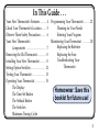
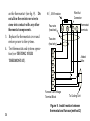
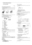
INSTALLATION &
OPERATING MANUAL
1F60-22
SETBACK
THERMOSTAT
PHOTO --POSITION ONLY!
(For use on 24 Volt AC Heat/Cool and Heat-Only Systems)
Homeowner: Save this booklet for future use!
Congratulations!
You have selected the 1F60-22 Setback thermostat. This state-of-the-art thermostat
enables you to enjoy maximum comfort and convenience. This thermostat automatically changes temperature settings, which keeps your home comfortable and increases your system’s efficiency while you save time.
Your new thermostat is....
• easy to install. You only need one regular screwdriver — all other hardware is
included.
• easy to operate.
• equipped with built-in minimum timing cycles, which increase system efficiency
and life.
Please read this manual thoroughly before beginning thermostat installation. If you
have questions you may call our technical service department at 1-314-577-1300 or
toll free at 1-800-876-TECH (8:00 AM to 4:30 PM CST).
2
In This Guide . . .
Your New Thermostat's Features . . . . . . 4
Check Your Thermostat's Location. . . . . 5
Observe These Safety Precautions . . . . . 6
Your New Thermostat's
Components . . . . . . . . . . . . . . . . . . 7
Removing the Old Thermostat . . . . . . . . 8
Installing Your New Thermostat . . . . . . 8
Setting Option Switches . . . . . . . . . . . . . 12
Testing Your Thermostat . . . . . . . . . . . . 13
Operating Your Thermostat . . . . . . . . . 15
The Display
The Time Set Button
The Setback Button
The Switches
Minimum Timing Cycles
Programming Your Thermostat . . . . . . 21
Planning for Your Needs
Entering Your Program
Maintaining Your Thermostat . . . . . . . 28
Replacing the Batteries
Replacing the Fuse
Troubleshooting Your
Thermostat
Homeowner: Save this
booklet for future use!
3
YOUR NEW THERMOSTAT’S FEATURES
4
• This thermostat incorporates easy
one-finger operation.
• The thermostat has a liquid crystal
display (LCD) that alternately
displays time and temperature and
shows system status. Celsius
temperature display is optional.
• The thermostat has indicators for
AM/PM mode, “setback on”, “cool
on”, and “heat on”.
• The thermostat divides the time of
day into 15-minute blocks, providing 48 possible setbacks over a 24hour period.
• To provide higher efficiency and
better temperature control, and to
help increase the life of your system,
this thermostat has automatic
minimum cycle on and off timing.
• During power outages, the thermostat is powered by two standard
1.5V watch batteries. One set of
batteries is included with your
thermostat. Thermostat programming and clock operation are not
affected by power outages when
batteries are installed.
• The thermostat has a temperature
differential switch for controlling
temperature within either 1° F or 3°F
of the set temperature.
• This thermostat controls heat/cool,
heat-only, and electric heat systems.
• This thermostat is capable of meeting HUD requirements (may be
field-disabled). This thermostat
also meets all state and federal
energy efficiency requirements.
CHECK YOUR THERMOSTAT’S LOCATION
You should install your thermostat about
five feet (1.5 meters) above the floor in an
area with good air circulation and
average temperature. Normally, you can
simply replace your old thermostat with
your new one.
However, you may consider changing
the thermostat’s location if the thermostat is affected by:
• drafts or dead air spots behind doors
and in corners.
• direct exposure to hot or cold air
blowing from ducts.
• direct exposure to sunlight or heat
from appliances.
• pipes or chimneys located behind
the wall where the thermostat is
located.
• unheated areas behind the thermostat, such as an outside wall.
5
OBSERVE THESE SAFETY PRECAUTIONS
WARNING
• DO NOT USE on circuits exceeding
specified voltage -- higher voltage
will damage thermostat, and may
cause shock or fire hazard.
• DO NOT SHORT OUT TERMINALS on gas valve or primary
control to test. Shorts or incorrect
wiring will burn out heat anticipator, and may cause personal injury
and/or property damage.
• DISCONNECT POWER at the main
fuse or circuit breaker box before
beginning thermostat removal/
installation. This will prevent
electrical shock and/or damage to
the heating/cooling system or
thermostat.
6
CAUTION
• If in doubt about whether you
wiring is millivolt, line, or low
voltage, have it inspected by a
qualified heating/air conditioning
contractor.
• Do not exceed specification ratings
(24 v AC -- 30v AC max., 1 amp.)
• Wiring must conform to local and
national codes and ordinances.
• This thermostat is a precision
instrument and should be handled
carefully. Rough handling or
distorting components could cause
the thermostat to malfunction.
YOUR NEW THERMOSTAT’S COMPONENTS
Your thermostat consists of two parts:
the base and the cover. To remove the
cover, grasp it and pull it out from the
base. Take a few minutes to become
familiar with the location of switches and
buttons on the thermostat. You will use
them during installation and operation of
your new thermostat. To replace the
cover, align the cover with the base and
push until it snaps into place. Do not
force the cover onto the base, as this may
damage the thermostat.
8.
9.
10.
11.
12.
13.
14.
Fan Switch (used on heat/cool systems only)
Setback Switch
System (Cool-Off-Heat) Switch
Batteries
SET BACK Button
TIME SET Button
F°/C° Switch
2
3
4
1
3° 1°
W Y G R
°F
14
5
°C
6
1. Liquid Crystal Display (LCD)
2. 1°/3° Differential Switch
3. Fuse
4. Terminal Screws
5. Temperature-Set Sliding Switch
6. Gas/Electric Heat Switch
7. Reset Button
12
13
11
10
9
8
7
Figure 1. Thermostat base
7
REMOVING THE OLD THERMOSTAT
1.
2.
Disconnect 120v AC power.
Remove the cover from the old
thermostat.
3. Remove terminal wires one at a time.
As you remove each wire, tag the
wire with the terminal identification
(such as Y, W, R) as shown on the old
thermostat base.
4. When all wires are removed, remove
the old thermostat base from the wall.
INSTALLING YOUR NEW THERMOSTAT
1.
2.
Disconnect120v AC power.
Remove the thermostat cover from
the base.
3. Pull the wires through the opening
above the terminal screws on the
thermostat base. Check the wire
ends; they should be stripped and
corrosion-free.
8
STOP!
If your system has five or six wires, read
the following cautionary statements. If
your system has two or four wires, go
directly to step 4.
CAUTION
NOTE
For systems where neither or
only one of the transformers is
grounded, you may use this
thermostat only if the transformers are properly phased. Use fig.
4 to wire the thermostat. If you
are not sure of your particular
application, contact a qualified
service person or call the technical service number found
elsewhere in this booklet.
If you have a two-transformer
(5-wire) system and both heat
and cool transformer secondaries are grounded, you cannot
use this thermostat, even if the
transformers are properly
phased.
Never connect the common
(neutral) wire on the 24v AC
side of the transformer to the
thermostat.
4.
Connect wires to the appropriate
terminals on the base. See table 1 and
figs. 2, 3, and 4 to match the tagged
wires with the correct terminals.
9
TYPICAL SYSTEM WIRING DIAGRAMS
Thermostat Terminals
Thermostat Terminals
W Y G R
W Y
G
R
Fan Relay
Cooling System
Hot
Hot
Heating
System
24v
Heating
System
120v AC
Neutral
Transformer
Figure 2. 2-Wire Heat-only
Thermostat Terminals
W Y
G
Fan Relay
24v
Cooling
System
24v
120v AC
Neutral
Transformer
Hot
120v AC
Neutral
Transformer
10
120v AC
Neutral
Transformer
Figure 3. 4-Wire Heat/Cool
Table 1. THERMOSTAT WIRING
R
Hot
Heating
System
24v
Figure 4. 5-Wire
(2-transformer) Heat/Cool
OLD THERMOSTAT
W-R
MARKINGS
MARKINGS
R, RC and/or
R
RH*, or V
G or F
G
Y, C, or Y6
Y
W, H, or 4
W
* On systems that have both RC
and RH wires, see cautionary
statements for 5-wire system
5.
6.
7.
8.
9.
When connections are complete,
push excess wire back into the wall’s
opening. Plug the opening with a
fire-resistant insulating material, such
as fiberglass insulation, to prevent
drafts that could affect thermostat
operation.
Attach the thermostat base to the wall
using the two screws provided.
Check the wires on the thermostat
base terminals; they should not be
touching one another or any other
part of the thermostat.
Set the option switches to desired
positions (see SETTING OPTION
SWITCHES).
Reconnect 120v AC power to system.
The thermostat display should now
be operating.
NOTE
If 120v AC power is to be
disconnected immediately after
thermostat installation, omit
step 10 (to conserve battery
power). Perform step 10 when
power is restored to the system.
10. Pull battery insulation tab down
firmly and remove. This will engage
the batteries.
11. Replace the thermostat cover.
Ensure that the system switch is in
the Off position before you begin
testing (see TESTING YOUR
THERMOSTAT).
11
SETTING OPTION SWITCHES
The 1°/3° DIFFERENTIAL SWITCH is
located to the right of the display on the
base. The thermostat is preset at 1°F. At
this setting, the thermostat will maintain
the room temperature within 1°F of the
set temperature (this results in more
frequent system on/off cycles). If you
move the switch to the left, the thermostat will maintain the room temperature
within 3°F of the set temperature (resulting in longer on/off cycles). Normally,
the 1°F setting is used.
The F°/C° SWITCH is located below the
display on the base. When you move the
switch up, the temperature will be
12
displayed in degrees Fahrenheit. When
you move the switch down, the temperature will be displayed in degrees Celsius.
The GAS/ELECTRIC SWITCH is located
above the setback switch on the base.
When you move the switch right, the fan
will turn on immediately when the
furnace turns on (for electric heaters).
When you move the switch to the left,
the fan will come on after the furnace
warms up (for gas furnaces).
TESTING YOUR THERMOSTAT
Follow these steps to ensure that your
thermostat is correctly installed. You
may want to refer to YOUR NEW
THERMOSTAT’S COMPONENTS to
help you locate switches you will use
during testing. If at any time during
testing your system does not work as
indicated, stop testing immediately,
disconnect the batteries and the 120v
AC power, and check thermostat
wiring. If wiring is correct, see TROUBLESHOOTING YOUR THERMOSTAT.
1.
Move the system (Cool-Off-Heat)
switch to the Off position.
NOTE
If you have a heat only system,
omit steps 2 and 3. Go directly
to step 4.
2.
(For heat/cool systems only). Move
the fan switch to the Cont. position.
The system fan should come on.
Move the fan switch to the Auto
position. The system fan should turn
off.
13
CAUTION
If the outside temperature is
below 40°F, OMIT STEP 3.
Running the air conditioner
when the temperature is below
40°F can damage the compressor.
3.
14
(For heat/cool systems only). Move
the system switch to Cool. Move the
temperature-set switch until it is set
to a temperature that is approximately 5°F below the displayed room
temperature. The air conditioner
should come on within two minutes.
Move the temperature-set switch at
least 5°F above the displayed room
temperature. The air conditioner
should shut off within two minutes.
4. Move the system switch to Heat.
Move the temperature-set switch
until it is set to a temperature that is
approximately 5°F above the displayed room temperature. The
furnace should come on within two
minutes. Move the temperature-set
switch at least 5°F below the displayed room temperature. The
furnace should turn off within two
minutes (although the fan may
continue to run for several more
minutes).
OPERATING YOUR THERMOSTAT
Use this section to learn about the
operation of the display, buttons, and
switches on your new thermostat. You
will also find information about the
thermostat’s built-in minimum timing
cycles. If you installed your thermostat,
you are already familiar with the display
and switch locations. If someone else
installed your thermostat for you, you
may want to refer to YOUR NEW
THERMOSTAT’S COMPONENTS to
help you locate buttons and switches on
the thermostat. After you are familiar
with the operation of your thermostat,
refer to PROGRAMMING YOUR
THERMOSTAT to set your thermostat
for your needs.
Before you begin this section, move the
system switch to the Off position. This
will prevent the system from cycling and
causing possible damage while you
experiment with the buttons and
switches.
15
THE DISPLAY
The display indicates system status in
three ways (see fig. 5).
A
P
Figure 5. LCD Display
1.
AM/PM display: When the A is
displayed, the time indicated is AM.
When the P is displayed, the time
indicated is PM.
2. Time/temperature display: The time
display is a 12-hour clock. The
16
temperature is displayed either in
degrees Fahrenheit or degrees
Celsius, depending on which option
you choose (see SETTING OPTION
SWITCHES). The time and temperature are alternately displayed.
3. Indicator arrows: These arrows
indicate which part of the system is
currently operating. The top arrow
indicates that the setback mode is
activated. The middle arrow indicates that the heating system is
activated. The bottom arrow indicates that the cooling system is
activated (if applicable). If you
currently have the system switch in
the Off position, there may not be
any arrows displayed.
THE TIME SET BUTTON
TIME
SET
Press and release the time set button.
The time setting will advance one
minute. Press and hold down the time
set button. The time setting will advance
one minute per second for four seconds.
Then it will advance rapidly through the
24-hour time period.
THE SETBACK BUTTON
SET
BACK
You will use the setback button to
program the temperature setback time
periods you want. Press and release the
setback button. The top arrow on the
display should now be visible. Press and
release the setback button again. The
setback indicator on the display should
now be off. You will find more information about using the setback button in
PROGRAMMING YOUR THERMOSTAT.
THE SWITCHES
You use the temperature-set sliding
switch to set the desired room temperature. The actual room temperature may
vary from the temperature you set,
depending on setback switch and
differential option switch settings.
You use the system (Cool-Off-Heat)
switch to activate (or deactivate) your
system. When the switch is in the Off
17
position, all systems will be off. When
the switch is in the Heat position, the
thermostat will cycle only the heating
system. If you have a heating/cooling
system, when the switch is in the Cool
position, the thermostat will cycle only
the cooling system.
The setback switch allows you to
determine how much the temperature
will change during setback periods. The
switch settings (0°F, 5°F, 10°F, and 15°F)
indicate how much the temperature will
be adjusted during setback periods. You
will find more information about using
the setback switch in PROGRAMMING
YOUR THERMOSTAT.
18
You use the fan switch only if you have
a heat/cool system. When the switch is
in the Auto position, the fan will cycle
automatically when the heat/cool system
turns on. When the switch is in the Cont.
position, the fan will run continuously.
The option switches allow you to adjust
your thermostat to meet your needs.
You will find more information about the
option switches in SETTING OPTION
SWITCHES.
You use the reset button if you want to
cancel any thermostat programming.
You also use this button to override
minimum cycle times.
MINIMUM TIMING CYCLES
The thermostat has built-in timing cycle
controls. These controls increase the
efficiency of your system and protect the
system from turning on and off excessively (excessive cycling may damage the
system or shorten its life).
In the heating mode, once the furnace
has turned on, it will continue to run for
at least four minutes, even if the set (or
setback) temperature is reached in less
than four minutes. If the room temperature does not reach the set/setback
temperature during the minimum
period, the furnace will continue to run
until the set/setback temperature is
reached. After the furnace turns off, it
will not turn on again for at least six
minutes. After six minutes, the furnace
will turn on if the room temperature is
below the set/setback temperature
range. The heat indicator arrow on the
display will flash if the furnace is waiting
to turn on after the six-minute minimum
cycle time has expired.
In the cooling mode, once the cooling
unit has turned on, it will continue to run
for at least six minutes, even if the set (or
setback) temperature is reached in less
than six minutes. If the room temperature does not reach the set/setback
temperature during the minimum
period, the cooling unit will continue to
19
run until the set/setback temperature is
reached. After the cooling unit turns off,
it will not turn on again for at least six
minutes. After six minutes, the cooling
unit will turn on if the room temperature
is above the set/setback temperature
range. The cool indicator arrow on the
display will flash if the cooling unit is
waiting to turn on after the six-minute
minimum cycle time has expired.
You may temporarily override the
minimum timing cycle in three ways:
• Move the temperature-set sliding
switch at least 5°F from its current
position.
20
• Move the system switch from its
current position and back (for
example, moving the system switch
from Heat to Cool and back to Heat
again will override the minimum
cycle time).
• Press the reset button to reset
programming and override minimum timing cycle. Pressing the
reset button will also cancel any
thermostat programming you have
done and reset the time of day to
12:00 PM.
PROGRAMMING YOUR THERMOSTAT
Programming your new thermostat is
easy. Follow these procedures for
planning and programming, then you
will be ready to enjoy complete comfort
and efficiency.
NOTE
Please save these instructions!
You may want to change your
thermostat programming at a
future date.
PLANNING FOR YOUR NEEDS
This thermostat is designed to provide
comfort and efficiency by allowing you
to program setback time periods. A
setback is a time period during which the
thermostat will automatically raise the
temperature (during the cooling season)
or lower the temperature (during the
heating season). Most users program
setbacks for times when they will be
sleeping or out of the house. When the
setback time period ends, the thermostat
automatically resets the temperature.
The thermostat allows you to program
setbacks in blocks as small as 15 minutes,
21
on the quarter hour (6:00 AM to 6:15 AM
or 10:30 PM to 10:45 PM are examples of
the smallest blocks of time you can
program for a setback).
Look at the sample programming table to
get an idea of how you can program your
thermostat. Table 2 shows programming
plans for a household where the home is
unoccupied during the day, and for a
household where the home is occupied
during the day.
Table 2. Samples of Typical Program Plans
Sample program when home is unoccupied during day
BEGIN
END
Setback
Setback
TypicalSchedule
Time
Time
Go to bed at 10:00 PM
10:00 PM
Wake up at 6:00 AM
Last person leaves for
work at 8:15 AM
5:45 AM
8:00 AM
First person arrives home
from work at 5:15 PM
5:00 PM
Sample program when home is occupied during day
Use table 3 (or make your own) to plan
the programmed setbacks you will need.
If you refer to your table while programming your thermostat, programming will
be much easier for you. Remember that
22
Go to bed at 10:00 PM
Wake up at 6:00 AM
10:00 PM
5:45 AM
Table 3. Your Programming Plan
Your Schedule
BEGIN
Setback
Time
END
Setback
Time
you can program up to 48 setbacks in a
24-hour period. This may be useful if
people in your household work different
shifts, or if your home is unoccupied for
short periods during the day or evening
(for example, you may want to use the
setback feature while you attend an
evening class).
ENTERING YOUR PROGRAM
Follow these steps to program your
thermostat. Before you begin programming, press the reset button to erase any
programs that you may have entered
while experimenting with your thermostat.
23
NOTE
You must complete steps 2
through 4 within one minute. If
you do not complete these steps
within one minute, start again at
step 1.
1.
Look at your programming plan
table 3 to determine your first
planned “begin setback” time, then
press and hold the time set button
until this time is displayed (also
check the display for the correct AM
or PM mode).
2. Press the setback button.
3. Check the display. The setback
indicator arrow should be on.
24
4.
Look at your programming plan
table 3 to determine your first
planned “end setback “time, then
press and hold the time set button
until this time is displayed.
5. Press the setback button.
6. Check the display. The setback
indicator arrow should be off.
Your first setback time is programmed!
To program all the setbacks you want,
just repeat steps 1 through 6 for each
begin/end setback time period. After
you have programmed all desired
setback time periods , you may want to
review your programmed setback
periods. If so, proceed to step 7. If you
don’t want to review your programming,
omit step 7 and proceed to step 8.
7.
Press and hold the time set button.
Watch the display. When a programmed “begin setback” time is
displayed, the setback indicator
arrow will turn on. You may check
the programmed “begin setback”
time by releasing the time set button
when the indicator arrow turns on
(keep in mind that the time displayed
will probably not be the exact time
you programmed, since it may take
you a moment to release the button
after the indicator arrow turns on).
Press and hold the time set button
again. When a programmed “end
setback” time is displayed, the
setback indicator arrow will turn off.
You may check the programmed
“end setback” time by releasing the
time set button when the indicator
arrow goes off. You may keep
pressing, holding, and releasing the
time set button until you have
checked all your programmed
setback time periods.
8. Set the time of day by pressing the
time set button until the correct time
is displayed (also check the AM/PM
mode).
9. Move the temperature-set sliding
switch (see fig. 6) to the temperature
you want maintained when the house
is occupied.
50
•
•
10
60 70 80 90 °F
• • • •
•
21
•
32 °C
Figure 6. Temperature-Set
Sliding Switch
25
10. Move the setback switch to the
desired position. The setback switch
has four settings (0°F, 5°F, 10°F, and
15°F). This switch tells the thermostat how much to adjust the temperature during setback periods. For
example, if (in the winter) you want
to maintain the temperature at 68°F
when the house is occupied, but you
want the temperature to be 63°F
when you are sleeping or the house is
unoccupied, you should move the
setback switch to 5°F. The thermostat
will then maintain the temperature at
5°F below the set temperature during
26
setback periods. Table 4 shows
examples of possible set temperatures
and setback switch combinations you
might use.
11. Move the system switch to Heat or
Cool as desired.
Your thermostat is now programmed
and will adjust the temperature when
setback program times are displayed.
To reprogram your thermostat, press the
reset button to cancel previous programming. Then you may reprogram by
following the above steps.
Table 4. Set/Setback Temperature Examples
SAMPLE TEMPERATURE/SETBACK
TEMPERATURES FOR HEATING SEASON
If set
temperature
....during setback
when home is ....and setback periods, the
occupied is... switch is set to.... temperature will be....
68°F
0°F
68°F
63°F
5°F
58°F
10°F
53°F
15°F
72°F
0°F
72°F
67°F
5°F
62°F
10°F
57°F
15°F
75°F
0°F
75°F
70°F
5°F
65°F
10°F
60°F
15°F
SAMPLE TEMPERATURE/SETBACK
TEMPERATURES FOR COOLING SEASON
If set
....during setback
temperature
when home is ....and setback periods, the
occupied is... switch is set to.... temperature will be....
72°F
0°F
72°F
77°F
5°F
82°F
10°F
87°F
15°F
75°F
0°F
75°F
80°F
5°F
85°F
10°F
90°F
15°F
79°F
0°F
79°F
84°F
5°F
89°F
10°F
94°F
15°F
27
MAINTAINING YOUR THERMOSTAT
When properly installed and maintained,
your new thermostat is designed to
provide years of service. This section
contains information about replacing
batteries and troubleshooting the
thermostat and system. This information
is provided to help ensure that your
thermostat will continue to provide
complete comfort control.
REPLACING THE BATTERIES
Two batteries have been included with
your thermostat. These batteries provide
power to the thermostat during any
power interruptions. The thermostat is
28
not designed to run on battery power
alone, but the batteries will maintain
your programming and the time of day
in the event of a power interruption.
Battery life is dependent on system
switch position and frequency and
duration of power interruptions. To
maintain full battery power at all times,
you should replace the batteries once a
year.
The thermostat’s batteries are the same
type used in many watches and digital
clocks. These batteries are available in
most stores that carry watch batteries,
and the dealer where your thermostat
was purchased should also carry replacement batteries.
You may use the following battery types
as replacements: 303BP, WS14,
RW22,Type A, 8002, ANSI No. S-15, IEC
No. SR44, NEDA No. 1107SO, or equivalent.
Follow these steps to replace batteries.
1.
2.
Remove the thermostat cover.
Locate the batteries (they are above
the time set button).
3. Gently remove the old batteries. Be
careful not to damage the thermostat.
4.
Insert the new batteries with the flat
(+) side up.
5. Replace the cover.
If you are experiencing short battery life,
it may be due to the type or condition of
your heating/cooling system. To extend
battery life, you should follow one of
these two procedures.
PROCEDURE 1. Short battery life may
be caused by the opening of the furnace’s
high temperature limit switch during the
heating cycle. Limit switch opening may
be related to airflow reduction in the
system. Airflow reduction is often
caused by dirty filters, a loose fan belt,
blocked cold air returns, or having too
29
many registers closed. Check your
system to ensure that there are no airflow
problems.
If you continue to experience short
battery life after fixing airflow problems,
your furnace has a limit switch that
functions even when airflow is adequate.
In this case, a 24 V single-pole , normallyopen (SPNO) relay must be added to the
system using the following procedure.
CAUTION
A qualified service person
should perform this installation.
30
1.
Disconnect 120v AC power from the
system.
2. Obtain a 24v SPNO relay (No. 8A041).
3. Connect the limit switch to the
contact side of the relay (see fig. 7,
part B ).
4. Reconnect power to the system. Test
the system and thermostat (see
TESTING YOUR THERMOSTAT).
Thermostat
R W
Thermostat
R W
Limit
Transformer
Limit
Gas
Valve
Limit
Limit
Relay
Transformer
24 v
Neutral
Hot
120 v
Gas
Valve
24 v
Neutral
Hot
120 v
Limit
A
B
Typical wiring of gas furnace
Typical wiring method using SPNO
showing possible limit switch location
relay and limit in gas furnace
Figure 7. Relay Installation
PROCEDURE 2. Short
battery life may also be
caused by repeated power
interruptions. These furnaces
cause power interruptions
during normal operation:
Bryant, Payne, Day & Night,
and Carrier Series
579
580
585
48KLA
If you own one of these
systems, you should install
the resistor that was included
with your thermostat using
one of the three following
methods (depending on
system type).
31
CAUTION
1KΩ, 0.5W resistor
A qualified service person
should perform the resistor
installation.
D7
Method 1. (For heat/cool systems only.)
W
Disconnect 120v AC power from
system.
2. Install the resistor between the W
and Y terminals on the thermostat
(see fig. 8). Do not allow the resistor
to come into contact with any other
thermostat components.
Y
G
R
D6
1.
32
Figure 8. Install resistor
at thermostat (method 1)
CAUTION
Method 2. (For heat-only or heat/cool
systems.)
Do not connect the resistor to the
R terminal at the thermostat or
the furnace. System damage
will occur.
Replace thermostat cover and restore
power to the system.
4. Test thermostat and system operation (see TESTING YOUR
THERMOSTAT).
NOTE
This installation requires an
additional wire that will run
from the furnace low voltage
terminal block to the thermostat.
3.
1.
Disconnect 120v AC power from
system.
2. Attach a wire to terminal C on the
furnace low voltage terminal block.
Attach the wire’s other end to the
resistor using a wire nut connector.
Attach the resistor to the W terminal
33
on the thermostat (see fig. 9). Do
not allow the resistor or wire to
come into contact with any other
thermostat components.
3. Replace the thermostat cover and
restore power to the system.
4. Test thermostat and system operation (see TESTING YOUR
THERMOSTAT).
Wire Nut
Connector
1KΩ, 0.5W resistor
Four-wire
(heat/cool)
W
R
G
Y
Thermostat
Terminals
Two-wire
(heat only)
W
Added
Wire
R
Gh
Gc
C
Y
Furnace Low Voltage
Terminal Block
34
To Cooling Unit
Figure 9. Install resistor between
thermostat and furnace (method 2)
Method 3. (For heat-only or heat/cool
systems.)
NOTE
This installation requires an
additional wire that will run
between the W and C terminals
on the furnace low voltage
terminal block.
resistor using a wire nut connector.
Attach the resistor to the W terminal
on the furnace low voltage terminal
block (see fig. 10). Do not allow the
resistor or wire to come into contact
with any other furnace components.
3. Restore power to the system.
4. Test thermostat and system operation (see TESTING YOUR
THERMOSTAT).
1.
Disconnect 120v AC power from
system.
2. Attach a wire to terminal C on the
furnace low voltage terminal block.
Attach the wire’s other end to the
35
Four-wire
(heat/cool)
Two-wire
(heat only)
W
W
R
G
Thermostat
Terminals
Y
1 KΩ, 0.5W
Resistor
Wire Nut
Connector
R
Gh
If the thermostat has been incorrectly
wired, or if the thermostat’s specifications were exceeded, you must replace
the fuse. Check and correct the wiring
and/or the load, then follow these steps
to replace the fuse.
Added wire
1.
2.
Gc
C
Y
Furnace Low Voltage
Terminal Block
To Cooling Unit
Figure 10. Install resistor
at furnace (method 3)
36
REPLACING THE FUSE
Disconnect the 120v AC power.
Obtain a 1 amp., 250v, AGC type
Normal-Blo fuse.
3. Locate the old fuse above the
thermostat wire terminals. Remove
the old fuse.
4. Install the new fuse.
5. Replace the thermostat cover and
restore power to the system.
6. Test thermostat and system operation
(see TESTING YOUR THERMOSTAT).
TROUBLESHOOTING YOUR
THERMOSTAT
If you or your service person cannot
solve the problem using this manual as a
guide, you may call our technical service
line at 1-314-577-1300 or toll free 1-800876-TECH (8:00 AM to 4:30 PM CST).
If you suspect that your thermostat is not
working correctly, use table 5 to help you
isolate the problem. You may be able to
solve the problem yourself, but some
procedures should be performed only by
a qualified service person (this is noted
in the “Action” column).
37
Table 5. Troubleshooting Table
PROBLEM
No display
POSSIBLE
CAUSE
ACTION TO TAKE
1. Miswired
• Check thermostat wiring.
2. No voltage to
thermostat
• Remove batteries. Check for 20-24v AC between R
& W terminals with system switch in OFF position.
If no voltage, check for limit switch operation.
3. Switch in Cool
position on heat
only system
• Move system switch to Heat position and replace
batteries.
OPERATING YOUR THERMOSTAT;
MAINTAINING YOUR THERMOSTAT
4. Blown fuse
• Check wiring. Replace fuse.
MAINTAINING YOUR THERMOSTAT
Heat will not turn 1. Not in Heat mode • Move system switch to Heat position.
on
2. Not calling for heat • Check heat indicator arrow on display. If off, move
temperature slide to the right and ensure thermostat
is not in setback mode.
INSTALLING YOUR THERMOSTAT
------
OPERATING YOUR THERMOSTAT
OPERATING YOUR THERMOSTAT
3. Bad gas valve, no
pilot, bad relay
open limit
• Ensure heat indicator arrow is on. Check for voltage
at gas valve. Call 800 number for assistance.
OPERATING YOUR THERMOSTAT
4. Blown fuse
• Check wiring. Replace fuse.
MAINTAINING YOUR THERMOSTAT
(Table continued on next page)
38
IN MANUAL,
REFERENCE SECTION ...
PROBLEM
Cooling system
will not turn on
POSSIBLE
CAUSE
ACTION TO TAKE
IN MANUAL,
REFERENCE SECTION ...
• Move system switch to Cool
OPERATING YOUR THERMOSTAT
2. Not calling for cool • Check cool indicator arrow on display. If off, move
temperature slide to the left and ensure thermostat
is not in setback mode.
OPERATING YOUR THERMOSTAT
1. Not in Cool mode
3. Bad compressor
contactor
• Check for voltage at compressor contactor - call
service person for repair.
------
4. Blown fuse
• Check wiring. Replace fuse.
MAINTAINING YOUR THERMOSTAT
Large
temperature
swing
1. Thermostat
location
• Relocate thermostat.
CHECK YOUR THERMOSTAT'S
LOCATION
2. Differential switch
set to 3°F
• Move differential switch to 1°F.
SETTING OPTION SWITCHES
On/off cycles
too short
1. Thermostat
location
• Relocate thermostat.
CHECK YOUR THERMOSTAT'S
LOCATION
2. Differential switch
set to 1°F
3. Miscalibrated
• Move differential switch to 3°F.
SETTING OPTION SWITCHES
Frozen display
1. Static electricity
• Thermostat is calibrated at factory at 70°F and should
need no further calibration - if calibration is needed,
call 800 number for assistance.
• Push reset button.
-----OPERATING YOUR THERMOSTAT
39
If you need further information on installation or programming
instructions, you may call our technical service department (8:00 AM
to 4:30 PM CST) at 1-314-577-1300 or toll free at 1-800-876-TECH.
37-4693A
8946