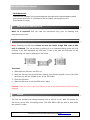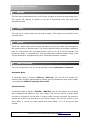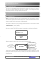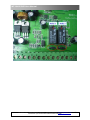
1
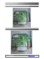
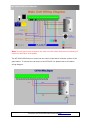
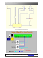
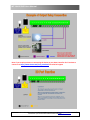
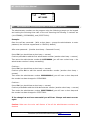
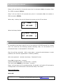
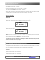
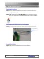
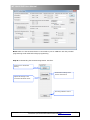
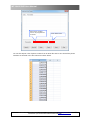
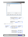
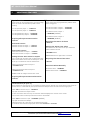
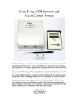
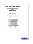
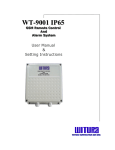
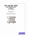
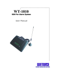
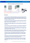
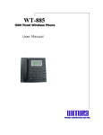
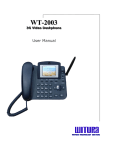
WT-9002 IP65 G GS SM M IIn ntte errcco om m A An nd d A em m Acccce essss C Co on nttrro oll S Sy ysstte User Manual W R R R W T U A C O P O A T O N S D N B H D WIIIT TU UR RA AC CO OR RP PO OR RA AT TIIIO ON NS SD DN NB BH HD D WT-9002 IP65 User Manual WT-9002 GSM INTERCOM AND ACCESS CONTROL SYSTEM INSTALLATION & WIRING DIAGRAM WT-9002 IP65 – USER MANUAL – Rev.2.0 – Technical Support: [email protected] COPYRIGHT ©2010 WITURA CORPORATION SDN BHD 2 WT-9002 IP65 User Manual Note: The call point must connect to the main unit with cables that are not exceeding 15 meters to avoid poor voice quality. The WT-9002 GSM Intercom works with any other single button intercom system of the gate station. To connect the call point to the WT-9002 unit please refer to the below wiring diagram. WT-9002 IP65 – USER MANUAL – Rev.2.0 – Technical Support: [email protected] COPYRIGHT ©2010 WITURA CORPORATION SDN BHD 3 WT-9002 IP65 User Manual GND Inputs and Outputs Wiring Connections WT-9002 IP65 – USER MANUAL – Rev.2.0 – Technical Support: [email protected] COPYRIGHT ©2010 WITURA CORPORATION SDN BHD 4 WT-9002 IP65 User Manual Note: If you require assistant on connecting the device to your Gate Controller don’t hesitate to contact us at http://www.witura.com/chat_room.html for technical support WT-9002 IP65 – USER MANUAL – Rev.2.0 – Technical Support: [email protected] COPYRIGHT ©2010 WITURA CORPORATION SDN BHD 5 WT-9002 IP65 User Manual CONTENTS 1. Introduction…………………………………………………………………………………………………………………………….7 2. WT-9002 IP65 Features………………………………………………………………………………………………………….7 3. Installation Instruction……………………………………………………………………………………………………………9 4. WT-9002 IP65 Programming Instructions…………………………………………………………………………….11 4.1 Description………………………………………………………………………………………………………………………………11 4.2 Programming the Administrator Numbers via Phone Call…………………………………………………….13 4.3 Programming the Administrator Numbers via SMS……………………………………………………………….14 4.4 Read the Programmed Administrator Numbers via SMS……………………………………………………….15 4.5 Changing the Password via Phone Call…………………………………………………………………………………..15 4.6 Changing the Password via SMS…………………………………………………………………………………………….16 4.7 Changing the Administrator Numbers via Phone Call……………………………………………………………16 4.8 Changing the Administrator Numbers via SMS …………………………………………………………………….17 4.9 Disconnecting the call via the handset…………………………………………………………………………………..18 4.10 Programming the Guest List via Phone Call……………………………………………………………………………18 4.11 Programming the Guest List via SMS……………………………………………………………………………………….19 4.12 Programming the Guest List via Learning Mode………………………………………………………………………20 4.13 Remove Guest Number from the List……………………………………………………………………………………….21 4.14 Restore deleted Guest Number…………………………………………………………………………………………………23 4.15 Relay Function……………………………………………………………………………………………………………………………23 4.16 Activate relays via SMS……………………………………………….……………………………………………………………24 4.17 Extending latching time of relays via SMS………………………………….……………………………………………24 4.18 Temporary latches the relays via Phone Call……………………………………………………………………………25 4.19 Temporary latches the relays via SMS…………………………………………………………………………………….26 4.20 Latches the Relays to Stay ON…………………………………………………………………………………………………27 4.21 Displays Programmed Administrator Number………………………….………………………………………………28 4.22 Access Control for Administrator and User………………………………………………………………………………28 4.23 Turn ON/OFF SMS Report from the Unit………………………………………………………………………………….28 4.24 Checking Signal Strength…………………………………………………………………………………………………………29 4.25 AC Power ON/OFF Alert Messaging………………………………………………………………………………………….30 4.26 Adjusting the Speaker volume of Intercom…………………………………………………………………………….30 4.27 Adjusting the Microphone volume of Intercom……………………………………………………………………….30 4.28 Adjusting the Ringing time when the system making a call……………………………………………………31 4.29 Turn ON/OFF the Sound of Alarm when Main Power Off…………………………………………………………31 4.30 Setting the Alarm Time Value……………………………..……………………………………………………………………32 4.31 Checking the system is operating correctly…………………………………………………………………………….32 4.32 Resetting the Unit……………………………………………………………………………………………………………………..32 4.33 Setting the Output Relays for Voltage Output or Dry Contact ……………………………………………….33 5. WT-9002 Programming Via PC…………………………………………………………………………………………………35 6. Function Summary……………………………………………………………………………………………………………………44 WT-9002 IP65 – USER MANUAL – Rev.2.0 – Technical Support: [email protected] COPYRIGHT ©2010 WITURA CORPORATION SDN BHD 6 WT-9002 IP65 User Manual 7. Additional Features…………………………………………………………………………………………………………………..45 8. Technical Specifications……………………………………………………………………………………………………………47 PACKAGE CONTENTS 1) 2) 3) 4) 5) 6) 7) 1. 1 1 1 1 1 1 1 pc pc pc pc pc pc pc IP65 Enclosure WT-9002 Main Board with GSM Module mounted Stainless Steel Call Point Power Adapter Battery Backup GSM Antenna LCD Display for Assisting in Programming INTRODUCTION GSM Intercom - The WT 9002 is the GSM Intercom in front of your gate that includes a speaker, microphone and “call” push button. When visitor at the gate presses the doorbell, the system will call to the house owner mobile phone if he is not at home. The owner can speak to the visitor and open the gate by simply pressing the passwords on his mobile phone GSM Access Control - The WT 9002 also is the access control system. You can register up to 1,000 users in the system if any of the users call to the gate automation system, it allows to open your gate with your mobile phone without any cost. – Absolutely Free Of Charges. You can just simply dial the mobile phone number in the WT 9002 from any phone and the WT 9002 will reject the call and open the gate without any cost. Of course, if not the register user, the door will never open. GSM Alarm System – The system can connect to motion sensor, Smoke detector, door and window sensors and if any intruder, the alarm system will triggered and it will send the SMS up to 3 mobile phone numbers, instantly alerting you unauthorized entry into the building. 2. WT-9002 IP65 FEATURES Remote Monitoring Your House & Gate While You Not At Home WT 9002 is work with 4 wire intercom which will be installed outside the premises or next to the gate as intercom system. When the bell button is pressed, the WT 9002 will dial the number preset inside and inform the owner that visitor at the gate. The owner can answer the call and speak to the visitor and open the gate by entering a pin code from his phone if he wishes to let the guest come in. The system can continue to call 2 consecutive numbers if the first number failed. WT-9002 IP65 – USER MANUAL – Rev.2.0 – Technical Support: [email protected] COPYRIGHT ©2010 WITURA CORPORATION SDN BHD 7 WT-9002 IP65 User Manual Only Register User Can Open the Gate – Up to 1,000 authorized users When one of the 1,000 register users call to the WT 9002, the system will recognized the caller ID number (phone number) and open the gate automatically. Put Up A Simple Alarm System While You Not At Home The system have 2 input can connect to the motion sensor, magnetic door sensor or smoke, gas & glass break sensors. If any intruder or emergency happen, the WT 9002 units will SMS up to 3 telephone number. Open The Gate Use Your Mobile Phone While You Not At Home If any visitor in front of your gate and you still not at home, you can open the gate to the visitor by pressing the 6 digit password at your mobile phone and the gate will open to allow the visitor come into the house. Remote Control to Switch On/Off Lighting, Air Conditional and Any Electrical Appliances The System has 2 Outputs and you can call in to switch on / off the electrical appliances. For example to switch on the Air Conditional before you enter into the house. Backup battery to Prevent Power Failure - You House Will Keep Monitoring When Power failure WT 9002 has a rechargeable battery that powers the system for minimum of 8 hours in the even of a power failure. The battery system will continue to use your utility power until power failure is detected. Once power failure is detected, the battery backup will instantaneously begin to supply and once utility power is restored, the backup will automatically switch off. Use With Any door bell or Intercom System WT 9002 will supply together with doorbell. If you prefer other design, you can choose to let the WT 9002 to work with any other Intercom system or doorbell. Just simply connect the 4 wires from WT 9002 to the other manufacturer doorbell system, it will work well. PC Programming WT 9002 has a DB9 connector that can be used for PC programming. Just simply plug in the provided RS232 cable to the DB9 port and the other end to your computer. By using the provided setting software, you are now able to program the unit easily. WT-9002 IP65 – USER MANUAL – Rev.2.0 – Technical Support: [email protected] COPYRIGHT ©2010 WITURA CORPORATION SDN BHD 8 WT-9002 IP65 User Manual IP 65 Enclosure The GSM unit is design fully protected against dust tight and protected against water jets from all directions. It is suitable to use at outdoor and complied to the International IP rating. 3. INSTALLATION INSTRUCTION Note: It is essential that you read the instructions fully prior to installing and programming the unit i) INSTALLING THE SIM CARD Note: Installing the SIM Card. Please be sure the initial 4 digit PIN code of SIM card is disabled. This can be done by placing it in an unlocked Mobile phone and first checking if the SIM requested any PIN code. If this is the case the PIN code can be disabled using the security settings on the phone. Procedure 1. Slide back the SIM door and lift it up 2. Slide the SIM card into the SIM door making sure that the clipped corner of the SIM card lines up with the clipped corner of the SIM holder 3. Close the SIM door 4. Slide the SIM door to lock the SIM card in place Caution: Make sure the voice mail feature of the all the administrators SIM Card are disabled ii) POWER The unit can operate with voltage between 12V to 24V AC or DC. Wait 15 seconds for the unit to set up after connecting power. The GSM Status LED will start to flash when the system is ready. WT-9002 IP65 – USER MANUAL – Rev.2.0 – Technical Support: [email protected] COPYRIGHT ©2010 WITURA CORPORATION SDN BHD 9 WT-9002 IP65 User Manual iii) MEMORY The unit can be programmed up to 1000 phone numbers to become as authorized users. The system will respond or answer to the call of authorized users only and reject unauthorized calls. iv) OUTPUT The unit has 2 outputs which can be used as output. The outputs are connected to an on-board relay v) RELAYS There are 2 output relays which can be activated by the person called via the keypad on the mobile phone or landline phone. The output relays are both set at factory default to latch for 1 second but can be programmed to latch on for up to 65,535 seconds. The function for Relay 1 is accessible by 1000 programmable authorized users. Relay 2 can only be activated or programmed by the 3 chosen administrator numbers. vi) OPERATION MODE The unit can operate in one out of two operation modes: Automatic or Password Automatic Mode If Automatic Mode is chosen (*TEL?#1, *ANY?#1), the unit will not answer any incoming calls including administrators number and will operate the relay output (Relay 1) automatically Without Incurring Cost of Call Password Mode If Password Mode is chosen (*TEL?#0, *ANY?#0), the unit will answer any incoming call immediately and indicate it by a short “Beep”. The unit will wait for a valid 6 digits pin code to be keyed in by the caller. If the pin code is correct, the caller can access to operate the output relay according to the function chosen. The unit will confirm by one short “Beep” a correct pin code entered and three “Beep” if it is a wrong pin code number. WT-9002 IP65 – USER MANUAL – Rev.2.0 – Technical Support: [email protected] COPYRIGHT ©2010 WITURA CORPORATION SDN BHD 10 WT-9002 IP65 User Manual vii) BACKUP BATTERY The unit has a rechargeable battery that powers the system for minimum of 8 hours in the event of a power outage. When the power is restored, it will recharge the battery automatically whenever the usage capacity fall below 9V. 4. WT-9002 IP65 PROGRAMMING INSTRUCTIONS 4.1 DESCRIPTION Note: As the WT-9002 IP65 can only be programmed by the 3 administrator numbers, you must first program those numbers into the unit. Anytime the administrators want to access the system, he/she must enter a 6 digit password. The system is initially set up using a 6 digit password and this is in the format as follows. *PAWO#123456 (Factory default) Once turn on the WT-9002 IP65, the system is setup and you shall see the following Settings: >>>> Search Wait… When the system is ready to use, you can see the following screen Working Indicator Signal Strength Indicator WT-9002 Power Indicator Battery Indicator If the system is working normally, the working indicator will keep on blinking. If it stops blinking this means the system is busy or freezes, you may want to restart the unit if it freezes too long. WT-9002 IP65 – USER MANUAL – Rev.2.0 – Technical Support: [email protected] COPYRIGHT ©2010 WITURA CORPORATION SDN BHD 11 WT-9002 IP65 User Manual When the system receives the programming message from the administrator, it will display a message icon on the top right corner of the screen as shown below… WT-9002 Message received After the programming message has been processed, the message icon will disappear and the system will shows “OK” indicate the setting has changed. OK WT-9002 When the system receives a phone call from the administrator, it will display “Admin” on the top and will prompt the administrator to enter password as shown below. Admin WT-9002 PW: After the administrator enters the correct password, then it will display “Menu”. At this state, the administrator is able to access the functions. MENU When the system receives a phone call, it will display the user numbers and if it is the number from the guest list, it will display “Guest” on the top of the screen. Otherwise, if it is an unknown number the system will display “No Guest” and the call is rejected. 3333333331 WT-9002 WT-9002 IP65 – USER MANUAL – Rev.2.0 – Technical Support: [email protected] COPYRIGHT ©2010 WITURA CORPORATION SDN BHD 12 WT-9002 IP65 User Manual Guest WT-9002 4.2 PROGRAMMING THE ADMINISTRATOR NUMBERS VIA VOICE The administrator numbers can be program using the following prompts on the keypad and making the following three calls to the unit assuming the following 3 numbers are (1111558888), (2222669999), and (3333770000). Example: Once the call has connected… (With a short beep ~ prompt the administrator to enter password, the initial set up password is 123456 by default) After enter password… (Another short beep ~ Password Correct) Press *3# (you should hear a short beep ~ success) Continue press 1# to add the first administrator number (another short beep ~ success) Then enter the administrator number 1111558888# (you will hear a short beep ~ the administrator number is setup successfully) Continue... Press *3# (you should hear a short beep ~ success) Continue press 2# to add the second administrator number (another short beep ~ success) Then enter the administrator number 2222669999# (you will hear a short beep and the number has been changed to 2222669999 Continue... Press *3# (you should hear a short beep ~ success) Continue press 3# to add the third administrator number (another short beep ~ success) Then enter the administrator number 3333770000# (you will hear a short beep and the number has been changed to 3333770000 If the change has not been successful you will hear 3 beeps and must re-enter again. Caution: Make sure the voice mail feature of the all the administrators numbers are disabled WT-9002 IP65 – USER MANUAL – Rev.2.0 – Technical Support: [email protected] COPYRIGHT ©2010 WITURA CORPORATION SDN BHD 13 WT-9002 IP65 User Manual TEL: 1#, 2#, 3# TEL: 1# TEL: 1111558888 1# TEL: 4.3 OK PROGRAMMING THE ADMINISTRATOR NUMBER VIA SMS The first 3 SMS messages sent to the unit would be as the following assuming the 3 Administration numbers are (1111558888), (2222669999), and (3333770000). Send the following 3 SMS Commands: 1) *TEL1#1111558888 2) *TEL2#2222669999 3) *TEL3#3333770000 As the first 2 numbers will be the customers own numbers you would program in the Installers number in *TEL3# This number can be changed once the system has been installed. When the system received the message and the number is programmed successfully, it will display “OK” on the screen and the administrator will receive a reply message from the unit. WT-9002 IP65 – USER MANUAL – Rev.2.0 – Technical Support: [email protected] COPYRIGHT ©2010 WITURA CORPORATION SDN BHD 14 WT-9002 IP65 User Manual Example of Return Message: TEL1=1111558888 TEL2=2222669999 TEL3=3333770000 4.4 READ THE PROGRAMMED ADMINISTRATOR NUMBERS VIA SMS It is possible to read all the programmed Administrator numbers by sending the following SMS to the unit. Send the following SMS Commands: *ADM?# Example of Return Message: TEL1: 1111558888 TEL2: 2222669999 TEL3: 3333770000 END 4.5 CHANGING THE PASSWORD VIA VOICE The system only allows the 3 administrator numbers as authorized user to change the 6 digits password. To change the password from the factory default 123456 to 654321 (Example) you can just call the unit and when the unit replies, you can use the following commands using the keypad prompts on your telephone. Once the call has connected … (With a short beep ~ prompt the administrator to enter password, the initial set up password is 123456 by default) After enter password… (Another short beep ~Password Correct) Press *2# (A short beep ~ success) WT-9002 IP65 – USER MANUAL – Rev.2.0 – Technical Support: [email protected] COPYRIGHT ©2010 WITURA CORPORATION SDN BHD 15 WT-9002 IP65 User Manual Then input the current password 123456# (you should hear a short beep ~success) Continue to enter new password 654321# for 2 times (another short beep if password entered correctly) If the change has not been successful you will hear 3 beeps and must re-enter again. 4.6 CHANGING THE PASSWORD VIA SMS The system only allows the 3 administrators to change the 6 digits password. To change the password from the factory default 123456 to 654321 (Example) you can just send the following SMS to the unit. Example: Sends a SMS Command: *PAWO#654321 If the change is successfully, the system will display “OK” on the screen and the administrator will receive a reply message from the unit. Returned Message: PAWO-OK 4.7 CHANGING THE ADMINISTRATOR NUMBERS VIA VOICE It is possible to change any of the administrator numbers using the following prompts on the keypad and making the following three calls to the unit assuming the following 3 numbers are to be changed as. Example: Change TEL1 to 4444444444 Change TEL2 to 5555555555 Change TEL3 to 6666666666 Once the call has connected… (With a short beep ~ prompt the administrator to enter password, the initial set up password is 123456 by default) WT-9002 IP65 – USER MANUAL – Rev.2.0 – Technical Support: [email protected] COPYRIGHT ©2010 WITURA CORPORATION SDN BHD 16 WT-9002 IP65 User Manual After enter password… (Another short beep ~ Password Correct) Press *3# (you should hear a short beep ~ success) Continue press 1# to change the first administrator number (another short beep ~ success) Then enter the new administrator number 4444444444# (you will hear a short beep and the number has been changed to 4444444444 Continue... Press *3# (you should hear a short beep ~ success) Continue press 2# to change the second administrator number (another short beep ~ success) Then enter the new administrator number 5555555555# (you will hear a short beep and the number has been changed to 5555555555 Continue... Press *3# (you should hear a short beep ~ success) Continue press 3# to change the third administrator number (another short beep ~ success) Then enter the new administrator number 6666666666# (you will hear a short beep and the number has been changed to 6666666666 If at any time the unit responds with 3 beeps then the number change has been unsuccessful and you must recall the unit and try again! 4.8 CHANGING THE ADMINISTRATOR NUMBERS VIA SMS It is possible to change any of the administrator numbers by sending a SMS command to the unit assuming the following 3 numbers are to be changed as. Example: Change TEL1 to 4444444444 Change TEL2 to 5555555555 Change TEL3 to 6666666666 WT-9002 IP65 – USER MANUAL – Rev.2.0 – Technical Support: [email protected] COPYRIGHT ©2010 WITURA CORPORATION SDN BHD 17 WT-9002 IP65 User Manual Simply sends 3 SMS command as below: 1) *TEL1#4444444444 2) *TEL2#5555555555 3) *TEL3#6666666666 The system will replace the current administrator numbers with the new administrator numbers and will reply as follow Example of Returned Message: TEL1=4444444444 TEL2=5555555555 TEL3=6666666666 4.9 DISCONNECTING THE CALL VIA THE HANDSET It is possible to disconnect the call being made from the call point to prevent the network holding the call after hanging up by using the following prompt on the handset whilst the call is active. Press *4# and the call will be disconnected. 4.10 PROGRAMMING THE GUEST LIST VIA VOICE To program numbers in the list via voice you would use the following prompts once you have called the unit and it has answered assuming you are programming in the following. Explanation of how it works: In WT-9002 memory, there are total of 10 lists with list number 0 – 9. The list number also represents the last digit of a phone number and each list can store up to 100 phone numbers. If the guest number is 2222222226, it will automatically store the number into list number 6. If the last digit of the guest number is 8, then it will be stored in list 8. Example: To program 2222222226 into the list: Press *5# (A short beep ~ success) Then you can input the phone number 2222222226# (A short beep ~ success) WT-9002 IP65 – USER MANUAL – Rev.2.0 – Technical Support: [email protected] COPYRIGHT ©2010 WITURA CORPORATION SDN BHD 18 WT-9002 IP65 User Manual And 2222222226 is programmed into list 6 Note: In the display screen of the unit, you should see as below. Guest: Continue input the guest number 2222222226 and ended with # Guest: 2222222226 And 2222222226 is programmed into list 6 4.11 PROGRAMMING THE GUEST LIST VIA SMS It is possible to program up to 1000 phone numbers to be authorized users in the white list of the unit and this can be done by sending SMS to the unit. To program up to the 1000 users at this time you have the option of using SMS text. Example: To program phone number: 3333333331 Sends SMS command *BOOK#3333333331 Hence 33333333331 is programmed into List 1 Returned Message: BOOK<<3333333331 For phone number: 22222222225 Sends SMS command *BOOK#2222222225 Hence 2222222225 is programmed into List 5 Returned Message: BOOK<<2222222225 WT-9002 IP65 – USER MANUAL – Rev.2.0 – Technical Support: [email protected] COPYRIGHT ©2010 WITURA CORPORATION SDN BHD 19 WT-9002 IP65 User Manual 4.12 PROGRAMMING THE GUEST LIST VIA LEARNING MODE It is possible to program the 1000 phone numbers into the Guest List via Learning Mode. To do this, you must first supply a 12VDC at Input 1 and turn on the unit as shown below. Once turn on the WT-9002 IP65, you shall see the following Settings: >>>> Search Wait… Input guest: 119 Timer Now the system is in learning mode. To program a phone number into the list, simply call the WT-9002 unit. When the WT-9002 received the incoming call, it will read the incoming caller ID and automatically program that number into the list. While in learning mode, you have 120 seconds to program a number. Every time the number is read and programmed, the timer will be reset. If there is no programming activity within 120 seconds, the WT-9002 will skip learning mode and proceed to standby mode. WT-9002 IP65 – USER MANUAL – Rev.2.0 – Technical Support: [email protected] COPYRIGHT ©2010 WITURA CORPORATION SDN BHD 20 WT-9002 IP65 User Manual Input guest: 100 13544456666 Input guest: OK 13544456666 The number has programmed successfully. Note: If one of the list for example list 1 is full, the new incoming number with last digit number 1 will not program into the list and shall display as the following. Input guest: FULL 13544456666 4.13 REMOVE GUEST NUMBER FROM THE LIST To remove numbers from the list you would send the following SMS assuming you wish to remove the following number from the list. Example: To remove a phone number: 6666666667 Simply sends a SMS Command *DEL>#6666666667 to the unit and it will search for number 6666666667 in the list and delete it. Returned Message: Delete-OK If repeated guest number is found in the list, it will search and delete the same numbers appear in the list. WT-9002 IP65 – USER MANUAL – Rev.2.0 – Technical Support: [email protected] COPYRIGHT ©2010 WITURA CORPORATION SDN BHD 21 WT-9002 IP65 User Manual 6666666667 WT-9002 >>>>>>>>>> WT-9002 >>>>>>>>>>>>>>>> WT-9002 Number Found Deleting the number Number deleted End WT-9002 To delete all numbers in the Guest List you would send the following SMS to the unit. Simply sends a SMS Command *DELB# to the unit and it will delete all programmed phone numbers in the list. Returned Message: Del-Book To permanently delete all numbers in the Guest List you would send the following SMS to the unit. Simply sends a SMS Command *DARE#1 to the unit and it will permanently delete all programmed phone numbers in the list. Returned Message: Delete-OK Warning: If all the numbers have been permanently deleted, it cannot be recovered. WT-9002 IP65 – USER MANUAL – Rev.2.0 – Technical Support: [email protected] COPYRIGHT ©2010 WITURA CORPORATION SDN BHD 22 WT-9002 IP65 User Manual 4.14 RESTORE DELETED GUEST NUMBER It is possible to restore the deleted phone numbers of Guest List and this can be done by sending the following SMS to the unit. Simply sends a SMS Command *DARE#0 to the unit and it will restore the deleted phone numbers. In the display screen of the unit, you should see as below. In data recovery Wait… In data recovery OK Returned Message: Recovery-OK Note: Phone numbers can be recovered with certain condition which is the number has been deleted with command *DEL># or *DELB# only. Certain phone number in the list cannot be recovered with *DARE#0 if some new numbers were programmed after issuing command *DEL># or *DELB#. All phone numbers cannot be recovered if were permanently deleted with command *DARE#1. 4.15 RELAY FUNCTION The output relays are both set at factory default to latch for 1 second. To activate the 2 output relays during a received call from the Call-Point you would use the following prompts via the telephone hand-set. Press *0# will activate relay 1 for 1 second at factory default. Press *1# will activate relay 2 for 1 second at factory default. Note: The latch time value can be changed via *EXT# command WT-9002 IP65 – USER MANUAL – Rev.2.0 – Technical Support: [email protected] COPYRIGHT ©2010 WITURA CORPORATION SDN BHD 23 WT-9002 IP65 User Manual Relay 1 can also be activated via caller ID from any number that has been programmed in to the authorized user list or the administrators. Relay 2 can only be activated and controlled by the 3 administrator numbers as programmed in to the unit. 4.16 ACTIVATE RELAYS VIA SMS It is possible to activate the relays to latch for 1 second at factory default by sending the below SMS command. Note: The latch time value can be changed via *EXT# command Send the following 2 SMS Command: 1) *ECL1# 2) *ECL2# Returned Message: ECLK1<OK> ECLK2<OK> 4.17 EXTENDING LATCHING TIME OF RELAYS VIA SMS It is possible to extend the latching time of both relays for up to the maximum of 65,535 seconds and to change both relay latching times you would send the following SMS command to the unit assuming relay 1 will be 10 seconds and relay 2 will be 60 seconds every time it activates. Example: Sending the following 2 SMS Command *EXT1#00010 *EXT2#00060 Example of Returned Message: EXT1=00010 EXT2=00060 WT-9002 IP65 – USER MANUAL – Rev.2.0 – Technical Support: [email protected] COPYRIGHT ©2010 WITURA CORPORATION SDN BHD 24 WT-9002 IP65 User Manual Relay 1 will now latch for 10 seconds every time it is activated (*0#) via handset, Caller ID or SMS command (*ECL1#) Relay 2 will now latch for 60 seconds every time it is activated (*1#) via handset or SMS command (*ECL2#) When relay 1 latches, the unit will display the counter on the LCD as shown. 00008 EXT WT-9002 When both relays latched… 00006 EXT 4.18 00058 WT-9002 TEMPORARY LATCHES THE RELAYS VIA PHONE CALL It is possible to latch both relays for up to the maximum of 65,535 seconds for a certain time. You would use the following prompts assuming relay 1 to be latched for 30 seconds and relay 2 to be latched for 120 seconds Once the call has connected… (With a short beep ~ prompt the administrator to enter password, the initial set up password is 123456 by default) After enter password… (Another short beep ~ Password Correct) Press *6# (A short beep ~ success) Continue press 1# for relay 1 (A short beep ~ success) Then input value 00030# (A short beep ~ success) Relay 1 will now latch for 30 seconds and after 30 seconds it will switch off and sends a message back to the administrator informed that Relay 1 has closed. Returned Message: RLY1-OFF WT-9002 IP65 – USER MANUAL – Rev.2.0 – Technical Support: [email protected] COPYRIGHT ©2010 WITURA CORPORATION SDN BHD 25 WT-9002 IP65 User Manual Press *6# (A short beep ~ success) Continue press 2# for relay 2 (A short beep ~ success) Then input value 00120# (A short beep ~ success) Relay 2 will now latch for 120 seconds and after 120 seconds it will switch off and sends a message back to the administrator informed that Relay 2 has closed. Returned Message: RLY2-OFF When relay 1 latches, the unit will display the counter on the LCD. 00008 RLY WT-9002 When both relays latch… 00008 RLY 00118 WT-9002 Note: Anytime if you want to cancel while it latches, you can always call to the unit and set the latching time back to 00000 and it will stops the relay. If at any time you hear 3 beeps the change has been unsuccessful and you will need to recall the unit and try again. 4.19 TEMPORARY LATCHES THE RELAYS VIA SMS It is possible to latch both relays for up to the maximum of 65,535 seconds for a certain time. To change both relay latching times by sending the following SMS. Example: Temporary latch Relay 1 for 60 seconds Temporary latch Relay 2 for 180 seconds WT-9002 IP65 – USER MANUAL – Rev.2.0 – Technical Support: [email protected] COPYRIGHT ©2010 WITURA CORPORATION SDN BHD 26 WT-9002 IP65 User Manual Simply send the 2 SMS command as below: *RLY1#00060 *RLY2#00180 Example of Returned Message: RELAY1=00060 RELAY2=00180 4.20 LATCHES THE RELAYS TO STAY ON It is possible to activate the relays to stay on by sending the below SMS command. The relays will stay ON until the switch OFF command is issued. Send the following 2 SMS Command: 1) *FRL1#1 – Latch Relay1 to stay ON 2) *FRL2#1 – Latch Relay2 to stay ON Returned Message: FRL1<ON> FRL2<ON> Send the following 2 SMS Command to turn OFF: 1) *FRL1#0 – Switch OFF Relay1 2) *FRL2#0 – Switch OFF Relay2 Returned Message: FRL1<OFF> FRL2<OFF> WT-9002 IP65 – USER MANUAL – Rev.2.0 – Technical Support: [email protected] COPYRIGHT ©2010 WITURA CORPORATION SDN BHD 27 WT-9002 IP65 User Manual 4.21 DISPLAY PROGRAMMED ADMINISTRATOR NUMBER To view the actual admin numbers programmed in you would just call the unit and prompt the following to view all 3 numbers. Once the call has connected… (With a short beep ~ prompt the administrator to enter password, the initial set up password is 123456 by default) After enter password… (Another short beep ~Password Correct) Press *7# (beep) and press 1# and the display will show you number 1 for 10 seconds Press *7# (beep) and press 2# and the display will show you number 2 for 10 seconds Press *7# (beep) and press 3# and the display will show you number 3 for 10 seconds 4.22 ACCESS CONTROL FOR ADMINISTRATOR AND USER It is possible to control the access of administrator or user to the system by sending the following SMS command to the unit. Sending SMS Command *ANY?#1, the system will allow only the administrators to gain access to the system and the authorized users in this case will not allow to access the system. (Factory Default: *ANY?#0 ~ Any person can gain access to the system) Note: It is advised that the owner should set the system to allow access only for administrators after programmed the Administrator numbers. Only the Administrator numbers in the list can send this command. Sending SMS Command *TEL?#1, the system will Not receive phone call from both administrators and users but will activate relay 1 immediately. (Factory Default: *TEL?#0 ~ able to receive phone call only from administrator but will not activate relay 1 immediately) 4.23 TURN ON/OFF SMS REPORT FROM THE UNIT It is possible to turn ON/OFF the request of report message when inputs triggered from the unit by sending the following SMS command to the unit. WT-9002 IP65 – USER MANUAL – Rev.2.0 – Technical Support: [email protected] COPYRIGHT ©2010 WITURA CORPORATION SDN BHD 28 WT-9002 IP65 User Manual Example of sending the below command: *RERN#100 (Factory Default) Only Administrator number 1# will receive a report message after setup Returned Message: RERN:<100> *RERN#110 Administrator number 1# and 2# will receive a report message after setup Returned Message: RERN:<110> *RERN#111 All the Administrators will receive a report message after setup Returned Message: RERN:<111> Sending the below command will turn Off this feature: *RERN#000 4.24 CHECKING SIGNAL STRENGTH To check the signal strength (0-31), you would send the following SMS command to the unit. *CSQ?# Example of Returned Message: CSQ=<27> WT-9002 IP65 – USER MANUAL – Rev.2.0 – Technical Support: [email protected] COPYRIGHT ©2010 WITURA CORPORATION SDN BHD 29 WT-9002 IP65 User Manual 4.25 AC POWER ON/OFF ALERT MESSAGING The unit is able to send alert message to the administrator in the event the main power is out / turned off. When the main power is restored it can notify the administrator again the main power is on. When main power OFF The unit will send a message: ACP-OFF Note: At the same time, it will send an ALWAYS high pulse out from I/O port. Alarm will sound. When main power restored The unit will send a message: ACP-ON 4.26 ADJUSTING THE SPEAKER VOLUME OF INTERCOM It is possible to adjust the speaker volume (from level 0 to 6) of the intercom by sending the following SMS command. Factory Default: 4 Example: Sending the following SMS Command *SOUD#5 – Adjust the volume to 5 Example of Returned Message: SOUND:<5> 4.27 ADJUSTING THE MICROPHONE VOLUME OF INTERCOM It is possible to adjust the microphone volume (from level 0 to 9) of the intercom by sending the following SMS command. Factory Default: 2 Example: Sending the following SMS Command *MIC0#5 – Adjust the volume to 5 Note: “0” Zero WT-9002 IP65 – USER MANUAL – Rev.2.0 – Technical Support: [email protected] COPYRIGHT ©2010 WITURA CORPORATION SDN BHD 30 WT-9002 IP65 User Manual Example of Returned Message: MIC0:<5> 4.28 ADJUSTING THE RINGING TIME WHEN THE SYSTEM MAKING A CALL This is the function that determines how many rings the unit will allow before the system will move on to the next number. This command will then apply for all 3 numbers. (Default: 20 seconds, maximum 60 seconds) Example: Adjust the ringing time to 15 seconds Example: Sending the following SMS Command: *TETI#15 Example of Returned Message: TETI:<15> 4.29 TURN ON/OFF THE SOUND OF ALARM WHEN MAIN POWER OFF It is possible to turn on/off the sound of alarm when main powers off by sending the following SMS command to the unit. Sending the below command will turn On the function: *ALAC#1 Returned Message: ALAC-ON Sending the below command will turn Off the function: *ALAC#0 WT-9002 IP65 – USER MANUAL – Rev.2.0 – Technical Support: [email protected] COPYRIGHT ©2010 WITURA CORPORATION SDN BHD 31 WT-9002 IP65 User Manual Returned Message: ALAC-OFF 4.30 SETTING THE ALARM TIME VALUE It is possible to set the alarm time up to maximum value of 65535 seconds by sending the following SMS command to the unit. (Default Value: 600) Example sending the following SMS Command: *ALTM#00060 – The alarm will sound for 60 seconds every time it triggered Example of Returned Message: ALTM:<00060> 4.31 CHECKING THE SYSTEM IS OPERATING CORRECTLY It is possible to check the system is operating correctly by sending the following SMS command to the unit. Send the following SMS Command: *TEST# When the unit replies TEST-OK indicate the unit is operating correctly. Note: If you receive no reply then unit is not working 4.32 RESET THE UNIT To reset the unit, you can send the following SMS command to the unit. Text Command: *REST#XXXXXX XXXXXX stands for 6 digits password based on *PAWO# (Default: 123456) and it can be changed anytime. WT-9002 IP65 – USER MANUAL – Rev.2.0 – Technical Support: [email protected] COPYRIGHT ©2010 WITURA CORPORATION SDN BHD 32 WT-9002 IP65 User Manual Warning: User can use their preset password to reset the unit and it must be noted down or remembered. In case if the password is forgotten or cannot be accessed, please consult our technical department. To manually reset the unit, you can press and hold on the “Call” button and turn on the unit for 10 seconds. The unit will displays Wait… and then OK, the unit is reset. 4.33 SETTING THE OUTPUT RELAYS FOR VOLTAGE OUTPUT OR DRY CONTACT To set the output relays to supply DC voltage (Based on the power adapter used) when activated, please adjust the jumper according to the below diagram. To set the output relays to dry contact when activated, please adjust the jumper according to the below diagram WT-9002 IP65 – USER MANUAL – Rev.2.0 – Technical Support: [email protected] COPYRIGHT ©2010 WITURA CORPORATION SDN BHD 33 WT-9002 IP65 User Manual WT-9002 IP65 – USER MANUAL – Rev.2.0 – Technical Support: [email protected] COPYRIGHT ©2010 WITURA CORPORATION SDN BHD 34 WT-9002 IP65 User Manual 5. WT-9002 Programming Via PC Installing the Software Step 1: Insert the provided WT-9002 CD into your computer. You will find a folder named “WT-9002 Programmer”. Step 2: Inside this folder you will find “WT-9002 Setting” file, you might want to copy this file into your computer. It is an executable program that does not require installation. Connecting the WT-9002 Device to Your Computer Step 3: Connect the WT-9002 device to your computer with a serial cable as shown below To your computer Launch the Software Step 4: Double click on the WT-9002 Setting.exe to launch the software. WT-9002 IP65 – USER MANUAL – Rev.2.0 – Technical Support: [email protected] COPYRIGHT ©2010 WITURA CORPORATION SDN BHD 35 WT-9002 IP65 User Manual Note: Make sure the WT-9002 device is connected to your PC COM Port with the provided programming serial cable before begin programming. Step 5: Understanding the WT-9002 Programmer interface. Press here for Serial Port Setting Download all settings from the WT-9002 device Upload all settings to the connected WT-9002 device Checking software version WT-9002 IP65 – USER MANUAL – Rev.2.0 – Technical Support: [email protected] COPYRIGHT ©2010 WITURA CORPORATION SDN BHD 36 WT-9002 IP65 User Manual Select the COM Port that WT9002 device has connected to Leave this section unchanged Establish connection with the WT-9002 device. Press this button when COM Port is selected. Programming the Administrator Numbers 1 – 3 *TEL[N]# Note: It is possible to program up to maximum of 16 digits for each administrator number. Programming the Guest list - *BOOK# WT-9002 IP65 – USER MANUAL – Rev.2.0 – Technical Support: [email protected] COPYRIGHT ©2010 WITURA CORPORATION SDN BHD 37 WT-9002 IP65 User Manual Enter phone number here to be programmed as Guest Press Add to save You can also import a list of phone number from an Excel file. But be sure that all the phone numbers are entered in the first column as shown below. WT-9002 IP65 – USER MANUAL – Rev.2.0 – Technical Support: [email protected] COPYRIGHT ©2010 WITURA CORPORATION SDN BHD 38 WT-9002 IP65 User Manual Access Control for Administrators *ANY?# Adjust the ringing time *TETI# Default: 20 seconds, maximum 60 seconds Turn ON/OFF the function of Input 1 *CTR1# Turn ON/OFF the function of Input 2 *CTR2# Setting the feature of Input 1 - *CTC1# Setting the feature of Input 2 - *CTC2# WT-9002 IP65 – USER MANUAL – Rev.2.0 – Technical Support: [email protected] COPYRIGHT ©2010 WITURA CORPORATION SDN BHD 39 WT-9002 IP65 User Manual Setting the Counter Alert Value of Input 1 *COA1# Setting the Counter Alert Value of Input 2 *COA2# Note: You are able to program the Counter Alert Value up to a maximum of 65535 only Turn ON/OFF Audible Siren function when Input 1 triggered *ALM1# Turn ON/OFF Audible Siren function when Input 2 triggered *ALM2# Setting the 6-digits Password for Reset Command - *PAWO# Setting Automatic Mode or Password Mode Turn ON/OFF Power Failure Alarm function *ALAC# Setting the Alarm Time for Audible Alarm *ALTM# Note: You are able to program the value of Alarm Time for Audible Alarm up to a maximum of 65535 only WT-9002 IP65 – USER MANUAL – Rev.2.0 – Technical Support: [email protected] COPYRIGHT ©2010 WITURA CORPORATION SDN BHD 40 WT-9002 IP65 User Manual Reset Input 1 SubCounter *CLC1# These values will be read from the WT-9002 device when pressed the upload button Reset Input 2 SubCounter *CLC2# Reset Input 1 Total-Counter *CLA1# Reset Input 2 Total-Counter *CLA2# Adjust the Microphone volume *MIC0# Adjust the Speaker volume *SOUD# Extending the latching time of relay 1 *EXT1# Extending the latching time of relay 2 *EXT2# Download all the Settings from the WT-9002 Device Step 6: Download all the settings from the WT-9002 device. To download all the settings, first you need to select the COM port number from the “Option” where the WT-9002 device has connected and press the “Open” button to establish a connection. WT-9002 IP65 – USER MANUAL – Rev.2.0 – Technical Support: [email protected] COPYRIGHT ©2010 WITURA CORPORATION SDN BHD 41 WT-9002 IP65 User Manual On the WT-9002 programmer software, you may notice that the “Upload” and “Download” button become visible. Now you may click on the “Download” button to download all the settings from WT-9002 device. Upload all the Settings to the WT-9002 Device Step 6: Upload all the settings to the WT-9002. To start programming all the settings, simply press the “Upload” button. WT-9002 IP65 – USER MANUAL – Rev.2.0 – Technical Support: [email protected] COPYRIGHT ©2010 WITURA CORPORATION SDN BHD 42 WT-9002 IP65 User Manual To logout the programmer software, simply click the X button on the top right. WT-9002 IP65 – USER MANUAL – Rev.2.0 – Technical Support: [email protected] COPYRIGHT ©2010 WITURA CORPORATION SDN BHD 43 WT-9002 IP65 User Manual 6. FUNCTIONS SUMMARY Functions of WT-9002 IP65 (Via Phone Call) 1) Activates Relay 1 *0# 5) Disconnecting the call via the handset *4# 2) Activates Relay 2 *1# 6) Programming the Authorized User List *5# 3) Changing the Password *2# 7) Temporary latch the relays *6# 4) Programming the Administrator Numbers *3# 8) Displays Programmed Administrator Numbers *7# Functions of WT-9002 IP65 (Via SMS) 1) Programming the Administrator Numbers via SMS *TEL1# *TEL2# *TEL3# 11) Access Control for Administrator and 2) Read the Programmed Administrator Numbers via SMS *ADM?# 12) Turn ON/OFF SMS Report from the 3) Changing the Password via SMS *PAWO# 4) Programming the Guest List via SMS *BOOK# 5) Remove Guest Number from the List *DEL># *DELB# *DARE#1 6) Restore Deleted Guest Number *DARE#0 7) Activate relays via SMS *ECL1# *ECL2# 8) Extending latching time of relays via SMS *EXT1# *EXT2# 9) Temporary latch the relays via SMS *RLY1# *RLY2# 10) Latches the Relays to Stay ON *FRL1# *FRL2# User *ANY?# *TEL?# Unit *RERN# 13) Checking Signal Strength *CSQ?# 14) Adjusting the Speaker volume of Intercom *SOUD# 15) Adjusting the Microphone volume of Intercom *MIC0# 16) Adjusting the Ringing Time when the System making a Call *TETI# 17) Turn ON/OFF the Sound of Alarm when Main Power Off *ALAC# 18) Setting the Alarm Time Value *ALTM# 19) Checking the system is operating correctly *TEST# 20) Resetting the Unit *REST# WT-9002 IP65 – USER MANUAL – Rev.2.0 – Technical Support: [email protected] COPYRIGHT ©2010 WITURA CORPORATION SDN BHD 44 WT-9002 IP65 User Manual 7. ADDITIONAL FEATURES: Input Counters Inputs Alarm These inputs can be programmed to count active high pulses. It needs to be activated by SMS to start counting. These inputs can be programmed by SMS to alarm when it triggered. Turn On (Activate) Input 1 - *CTR1#1 Turn On (Activate) Input 2 - *CTR2#1 Turn Off (Deactivate) Input 1 - *CTR1#0 Turn Off (Deactivate) Input 2 - *CTR2#0 Acquiring All Input Counters Value *COU?# Reset Sub Counter Reset Sub Counter for Input 1 - *CLC1# Reset Sub Counter for Input 2 - *CLC2# Reset Total Counter Reset Total Counter for Input 1 - *CLA1# Reset Total Counter for Input 2 - *CLA2# Setting Counter Alert Value for Inputs Every counter will increment until it reaches the alert value, and an alarm will be sent for that input. It can be set up to a maximum value of 65535 times. Setting Counter Alert Value for Input 1 - *COA1#XXXXX Setting Counter Alert Value for Input 2 - *COA2#XXXXX Turn On the Alarm of Input 1 - *ALM1#1 Turn On the Alarm of Input 2 - *ALM2#1 Turn Off the Alarm of Input 1 - *ALM1#0 (Default) Turn Off the Alarm of Input 2 - *ALM2#0 (Default) Acquiring the Status of Alarm *ALA?# Setting the Alarm Time Value The alarm time value can be set up to maximum value of 65535 seconds *ALTM#XXXXX XXXXX stands for 5 digits value in seconds Acquiring the Alarm Time Value *ALT?# Sound the Alarm Manually Sound the Alarm - *ALNF#1 Switch off the Alarm - *ALNF#0 XXXXX stands for 5 digits counter alert value. Acquiring All Input Counters Alert Value *COA?# Functions of I/O (Pin 1) When switched on, this I/O (Pin 1) can function as Input Counter and will only counts when it short circuit to ground. When it is switched off, this I/O will function as Output and it can send out active high pulse. Switch ON the function of I/O - *CODI#1 - I/O port will function as Input counter. - It can count when short circuit up to maximum 999 and displays the counter on the screen. - The counter value will be kept until this function is turned OFF. Switch OFF the function of I/O - *CODI#0 (Default) - I/O port will function as Output. - When AC power off, it can send out an ALWAYS high pulse. - It is able to send out active high pulse when used *CTC1#5 or *CTC2#5 WT-9002 IP65 – USER MANUAL – Rev.2.0 – Technical Support: [email protected] COPYRIGHT ©2010 WITURA CORPORATION SDN BHD 45 WT-9002 IP65 User Manual Multi-features Inputs These inputs can be programmed to behave differently, it can count input active high pulses, generate an alarm or activate relays. It needs to be activated first by SMS to start using the commands. Function Command for Input 1 - *CTC1#X Function Command for Input 2 - *CTC2#X X stands for Functions No. 1 – 8 Function No. 1 (Default) - Count whenever it receives active high pulses Function No. 2 - Count whenever it receives active high pulses - Activates Relay 1 (When Function No. 2 is apply on Input 1) or Activates Relay 2 (When Function No. 2 is apply on Input 2) Function No. 3 - Count whenever it receives active high pulses - Activates Relay 1 (When Function No. 3 is apply on Input 1) or Activates Relay 2 (When Function No. 3 is apply on Input 2) - Return a SMS: ECLK1<OK> - Alarm will sound Function No. 4 - Count whenever it receives active high pulses - When received an active high pulse, it will send an active high pulse for 1 second out from I/O port Function No. 5 - Count whenever it receives active high pulses - When received an active high pulse, it will send an active high pulse for 1 second out from I/O port - Return a SMS: OUT3<ON> - Alarm will sound Function No. 6 - Count whenever it receives active high pulses - Activates Relay 2 (When Function No. 6 is apply on Input 1) or Activates Relay 1 (When Function No. 6 is apply on Input 2) - Sends a SMS when counter reaches the alert value - Alarm will sound when the counter reaches the alert value Function No. 7 - Count whenever it receives active high pulses - Activates Relay 1 and Relay 2 - Sends a SMS when counter reaches the alert value - Alarm will sound when the counter reaches the alert value Function No. 8 - Count whenever it receives active high pulses - Activates Relay 1 to stay ON (When Function No. 8 is apply on Input 1) or Activates Relay 2 to stay ON (When Function No. 8 is apply on Input 2) - Return a SMS: ECLK1: ALWAYS-ON - Alarm will sound Note: It can be turned off by simply sends a SMS command *RLY1#00000 or *RLY2#00000 WT-9002 IP65 – USER MANUAL – Rev.2.0 – Technical Support: [email protected] COPYRIGHT ©2010 WITURA CORPORATION SDN BHD 46 WT-9002 IP65 User Manual 8. TECHNICAL SPECIFICATIONS Built in power supply 15 Volts 1 Amps and fused 2 amps. Dual Band (900/1800Mhz) or Quad Band Module (850/900/1800/1900Mhz) Power Supply: 100VAC ~ 250VAC Operating Temperature - 25 to 55°C Humidity Less than 95% RH. Lightning Protector: 3-5W 2 Output relays normally open 240 volts 1 amp. Can call up to 3 numbers outbound. Battery back-up for up to 8 hours. Caller ID for up to 1000 users. Connections for manual operation of both output relays. Programmable via SMS or Voice. Optional LCD for site programming and diagnostic status of system. Facility to switch off modem and retain hard wired Intercom if applicable. Comes in IP 65 enclosure with external flange mounting. C.E Approval WARRANTY Witura Corporation Sdn Bhd warrantees all WT-9002 GSM Access Control System against defective parts and workmanship for 1 year. Witura Corporation Sdn Bhd shall, at its option, repair or replace the defective equipment upon the return of such equipment to any Witura branch. This warranty applies ONLY to defects in components and workman-ship and NOT to damage due to causes beyond the control of Witura, such as incorrect voltage, lightning damage, mechanical shock, water damage, fire damage, or damage arising out of abuse and improper application of the equipment. Note: Wherever possible, return only the PCB to Witura Service Centres. DO NOT return the enclosure. The WT-9002 IP65 is a product of Witura Corporation Sdn Bhd And is Manufactured by Shenzhen Witura Telecommunications Co., Ltd. WARNING For safety reasons, only connect equipment with a telecommunications compliance label. This includes customer equipment previously labelled permitted or certified. WT-9002 IP65 – USER MANUAL – Rev.2.0 – Technical Support: [email protected] COPYRIGHT ©2010 WITURA CORPORATION SDN BHD 47