1
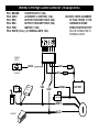
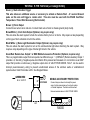
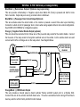
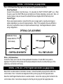
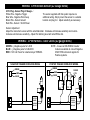
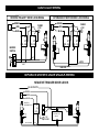
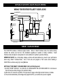
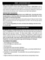
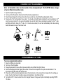
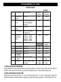
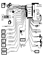
CS-2011RS
Super Rage™
Remote Control Alarm System & Remote Engine Starting System
INSTALLATION INSTRUCTIONS
INSTALLATION CAUTIONS & WARNINGS
To ease and reduce installation time, we suggest you consider the following points before starting:
BEFORE BEGINNING, check all vehicle manufacturer cautions and warnings regarding electrical service (AIR
BAGS, ABS BRAKES, AND BATTERY).
USE A VOLT/OHM METER to test and locate all connections. Test Lights can damage a vehicle’s computer
systems.
ADDITIONAL PARTS, which are not included with this unit, may be needed for your particular vehicle. These
items may include extra relays, Anti-Theft System Bypass modules, or Transponder Bypass modules.
TECHNICAL SUPPORT (800)-998-6880
Monday - Friday 8:00am - 4:30pm Pacific
Website: www.crimestopper.com
E-mail: [email protected]
CRIMESTOPPER
SECURITY PRODUCTS, INC.
1770 S. TAPO STREET
SIMI VALLEY, CA. 93063
This device complies with FCC Rules part 15. Operation is subject
to the following two conditions: 1) This device may not cause
interference, and (2) this device must accept any interference that
may be received, including interference that may cause undesired
operation. The manufacturer is not responsible for any radio or TV
interference caused by unauthorized modification to this
equipment. Such modification could void the user's authority to
operate the equipment.
INSTALLATION CAUTIONS & WARNINGS
DO NOT remote start the vehicle in a closed garage. Make sure that the garage door is open or there is
adequate ventilation. Failure to observe this rule could result in injury or death from poisonous Carbon
Monoxide fumes.
DO NOT ROUTE ANY WIRING THAT MAY BECOME ENTANGLED with brake, and gas pedals, steering
column, or any other moving parts in the vehicle.
ALLOW ENOUGH WIRE to create a service loop with strain relief, should servicing be required. This will also
allow easier access and mounting.
REMOVE MAIN SYSTEM FUSE(S) before jump-starting the vehicle or charging the battery at high boost.
DAMAGE MAY OCCUR TO SYSTEM IF PROPER PRECAUTIONS ARE NOT OBSERVED.
DO NOT exceed the rated output current of any circuit on the Remote start module. Failure to observe this
warning will result in damage to the unit.
DO NOT extend the CS2011RS Remote start ignition harness length. Mount the module so that main harness
reaches all ignition switch wiring. Extending these wires could result in poor performance.
COMPONENT MOUNTING
CONTROL MODULE: The alarm control module should be mounted in a concealed location. DO NOT mount
the control unit in the engine compartment.
ANTENNA / RECEIVER MODULE: For optimum range and performance, the antenna/receiver module should
be located high up on the front windshield glass. For example: behind the rearview mirror. Note: Window
tints or Films may adversely affect the range of the system. Mounting surface should be clean and dry.
SIREN MOUNTING: Mount the siren under the hood to fender-well or other body surface with the open end facing
downward. Run the red siren wire through the firewall using a rubber grommet. Ground the black wire to the body
metal near the siren.
LED: Mount the red LED in a visible location on the dashboard or console.
SHOCK SENSOR: Mount the included shock sensor with wire ties to an under dash wire harness or fasten with
screws to firewall or side paneling.
OVERRIDE/PROGRAM BUTTON: Mount the Override/Program push-button in a hidden but accessible location. It is
used for emergency disarm without the use of the transmitter and for programming purposes.
WIRING: 6-PIN High Current Connector (14 Gauge wires)
PIN 1: BROWN:
STARTER OUTPUT (30A)
PIN 2: GRAY:
ACCESSORY or IGNITION 2 (30A)
PIN 3: RED:
BATTERY CONSTANT FUSED (30A)
PIN 4: RED:
BATTERY CONSTANT FUSED (30A)
PIN 5: PINK:
IGNITION 1 (30A)
PIN 6: WHITE (18 Ga.): (+) PARKING LIGHTS (10A)
CAUTION!: CHECK ALIGNMENT
OF PLUG TO PINS. IF THE
HARNESS IS UPSIDE
DOWN, STARTER OUTPUT
WILL BE CONNECTED TO
PARKING LIGHTS!
PARKING
LIGHTS
RED
WHITE
FUSE
30A
RED
+10A MAX.
FUSE
30A
+
FUEL
PUMP
+
-
ENGINE
ECU
PINK
BROWN
GRAY
STARTER
COIL
IGN 1
HEAT/AC
ACC
BATTERY
-
WIRING: 9-PIN Harness (22 Gauge wires)
Green: (-) Start Activation Trigger
This wire allows an additional source or accessory to activate a Remote Start. A 1-second Ground
pulse on this wire will trigger a remote start. This wire must be used with the RS400 CoolTimer
Temperature / Timed Start Accessory (Not included).
Brown: (+) Siren Output
Connect brown wire to siren red wire. Connect black wire of siren to chassis ground (body metal).
Brown/White: (-) Horn Honk Output (Optional, may require relay)
This wire allow the alarm system to honk the vehicles factory horn or air horns. May require a relay depending
on the type of horn activation circuit in the vehicle.
Black/White: (-) Dome Light Illumination Output (Optional, may require relay)
This wire allows the alarm system to turn on the vehicles dome light when disarming the alarm system. May
require a relay depending on the type of dome light circuit in the vehicle.
Green/Red: Remote Aux. Output 1 or MAP-Mobile Accessories Protection (Optional, requires relay)
This is a programmable output that can operate two different ways: 1. (DEFAULT) Remote Auxiliary Output 1
provides a ½ Second (-) Negative pulse when Button #3 is pressed and released or it can function as an MAP
output that provides a continuous (-) Negative output when in VALET PARK MODE. M.A.P. can be used to
interrupt power/accessory wiring to prevent unauthorized access of the vehicle’s audio or entertainment
systems when Valet Park mode is ON. See Diagram Below.
GREEN/RED
M.A.P. OUTPUT
85
86
87
87A 30
+
IGN.
SWITCHED
MOBILE ACCESSORY PROTECTION
Connect relay as shown to interrupt the power
wire of mobile accessories such as Audio system
or Cellular telephone. The Alarm will disconnect
these accessories when in VALET PARK MODE.
OFF
105. 5 FM
ACC
IGN
START
CUT
RADIO
WIRING: 9-PIN Harness (22 Gauge wires)
Blue/Black: (-) Remote Aux. Output 2 (Optional, may require relay)
This wire provides a Momentary<-> Negative output when Button #3 (Trunk) is pressed and held for more
than 2 seconds. Output stays on as long a remote button is held down.
Blue/White: (-) Passenger Door Unlock Output (Optional)
This wire activates when the unlock button on the remote is pressed a second time when upon disarming.
Connects to unlock circuit for passenger door or doors when using separate driver’s door unlock configuration.
See DOOR LOCK WIRING for configuration options.
Orange: (-) Negative Starter Disable Output (optional)
This wire should be connected to the Yellow wire of the pre-wired relay socket for the starter disable. Connect
the blue wire of the relay socket to the Ignition switched wire on the vehicle. Cut the vehicle starter wire and
connect each half to an Orange wire on the relay socket. See Diagram Below.
IGNITION SWITCHED
"ON" & HOT THROUGH
CRANKING
IGN. SWITCHED
STARTER WIRE
CONNECT TO
ORANGE WIRE
OF ALARM
PRE-WIRED
STARTER DISABLE
RELAY & SOCKET
START OUTPUT
FROM ALARM
6-PIN HARNESS
CUT
YELLOW
STARTER
BLUE
ORANGE
ORANGE
BROWN
MAKE CERTAIN TO
CONNECT BROWN
WIRE TO STARTER
MOTOR SIDE.
Orange/Black: (-) OEM Disarm Output
This wire provides a Ground pulse to disarm vehicles' Factory anti-theft system prior to a Remote Start.
Connect this wire to the vehicles' anti-theft disarm wire. This wire is sometimes found coming off the Driver's
door key switch or at the Factory Anti-theft control module.
WIRING: 4-PIN Harness (18/22 gauge wires)
Red/White: Tachometer Input
When installing the CS2011RS in TACH REFERENCE mode, this wire must be connected to a valid source of
AC voltage. This wire allows the unit to sense the engine and control the starter motor.
Black: Chassis Ground
Connect to body metal of the vehicle using a sheet metal screw and a star washer.
Yellow/White: (-) Accessory Output (For Adding Accessory or IGN2 Relays)
Yellow: (-) Ignition 1 Output (For Adding Ignition Relays)
Use these wires when the vehicle requires a second IGNITION 1, IGNITION 2, or ACCESSORY wire to be
activated. This occurs commonly in Toyota, and late model GM cars. See diagram below.
YELLOW
OR
(YELLOW/WHITE)
85
86
30
87
+
BATTERY
2nd IGN 1
OR
(2nd IGN2 /ACC WITH YEL/WHT)
WIRING: 5-PIN Harness (22 gauge wires)
Violet: (+) Door Pin Switch Input
Connect to door switches that read +12 volts when door is opened. A (+) positive door switch wire will read (-)
ground when doors are closed.
Green: (-) Door Pin Switch Input
Connect to door switches that read ground when door is opened. A (-) negative door switch wire will read +12
volts when doors are closed.
Blue: (-) Hood/Trunk Pin Switch Input
Connect to pin switches that read ground when hood and trunk are opened. It may be necessary to install your
own switches. The kit includes a 6” brown wire end for connecting to the supplied hood pin switch terminal.
WIRING: 5-PIN Harness (22 gauge wires)
Pink: (+12V) Diesel Glow Plug Input or Car Jack Input (Programmable Input Wire)
Glow Plug (Diesel):
Connect to the indicator circuit that shows +12 volts while the “WAIT TO START LAMP” is on. When
this wire is used, the CS2011RS will wait until light turns off before attempting a remote start. Note: An
inverter module or relay can be used for vehicles that have a Negative Wait to Start lamp circuit.
Carjack Trigger
When using Carjack protection, connect this Pink wire to a toggle switch, or positive door trigger or
ignition depending on your level of Carjack protection. When +12V is applied to this wire with IGN on
and a door is opened then closed, a Carjack countdown will begin. See Diagram Below for optional
wiring configurations.
OPTIONAL CAR JACK WIRING:
HIDDEN BUTTON or
TOGGLE SWITCH
(Not Included)
PINK
IGN SW
+ IGN
+
CONTROLLED W/SWITCH
12 V
PINK
FULL-TIME CARJACK
White: (+12V) Brake Reset
Connect the Purple wire to the side of brake pedal switch that shows +12 volts ONLY when pedal is
depressed. This will turn off the remote start if someone attempts to drive the car without the keys or if the
Ignition key is not turned on all the way.
WIRING: 2-PIN LED / 2-PIN Program-Valet Button (22 gauge wires)
Mount LED in a visible location in the Dash or Console. Connect the small 2-pin plug from the LED to the
control module. Note: Connectors are designed so that they will only plug into their appropriate slots.
Mount the Valet/Program/Override button in a suitable location. Connect the 2-pin plug from the Switch to the
control module. Note: Connectors are designed so that they will only plug into their appropriate slots.
WIRING: 4-PIN Shock Sensor (22 Gauge wires)
4 Pin Plug - Sensor Plug 22 Gauge -:
White Wire - Negative Trigger
Blue Wire - Negative Warn Away
Black Wire - Sensor Ground
Red Wire - Sensor +12Volt Power
The sensor supplied with this system requires no
additional wiring. Simply mount the sensor in a suitable
location and plug it in. Adjust sensitivity as necessary.
Sensor Adjustment
Adjust the main shock sensor with the small black dial. Clockwise will increase sensitivity and counterclockwise will decrease sensitivity. Adjust Pre-Warning level with small White dial.
WIRING: 3-PIN Harness - Door Locks (22 gauge wires)
GREEN: (-) Negative pulse for LOCK
BLUE: (-) Negative pulse for UNLOCK
RED: +12V Coil Power for external relays TERM 86.
NOTE: A Low-cost CS-6500DLI inverter
module is available to convert Negative
CS2011RS lock/unlock signals for
Positive systems.
NEGATIVE TRIGGER DOORLOCK WIRING
POSITIVE TRIGGER DOORLOCK WIRING
GREEN
GREEN
RED
RED
BLUE
BLUE
FUSED
+12V
+
85
86
87
87A 30
L
UL
FACTORY
POWER
LOCKING
RELAYS
L
UL
85
86
87
87A 30
FACTORY
POWER
LOCKING
RELAYS
DOOR LOCK WIRING
REVERSE POLARITY DOOR LOCK WIRING
AFTERMARKET MOTOR/DOOR LOCK WIRING
GREEN
GREEN
FUSED
+12V
+
RED
BLUE
85
86
85
87
87A 30
FUSED
+12V
+
RED
BLUE
85
86
86
85
87
87A 30
87
87A 30
86
87
87A 30
MASTER
SWITCH
+
L
UL
CUT
LOCK
CUT
UNLOCK
SEPARATE DRIVER’S DOOR UNLOCK WIRING
NEGATIVE TRIGGER DOOR LOCKS
BLUE/WHITE
GREEN
RED
BLUE
DRIVER'S
DOOR MOTOR
85
86
87
30 87A
L
UL
+
UNLOCK WIRE
CUT
L
UL
+12V
FUSED
FACTORY LOCK
RELAYS
SEPARATE DRIVER’S DOOR UNLOCK WIRING
WIRING FOR REVERSE POLARITY DOOR LOCKS
BLUE/WHITE
GREEN
RED
FUSED
+12V
+
BLUE
MASTER
SWITCH
85
85
86
86
87
87A 30
87
30 87A
+
L
86
87
87A 30
CUT
UL
CUT
85
CUT
LOCK WIRE
UNLOCK WIRE
SMART TACHLESS MODE
The CS2011RS includes a Tachless engine monitor. When in Smart Tachless mode, the module actively
monitors the vehicle over the life of the installation regardless of weather or battery conditions. Smart
Tachless mode will adjust to compensate for most conditions for optimum operation efficiency.
IMPORTANT NOTE: Due to fluctuating voltages, vehicles with dual batteries may result in poor performance
when using “Smart” Tachless Mode. Use a Tach wire and program a Tach source when installing a
CS2011RS on vehicles using 2 [or more] Batteries.
SETTING UP THE SMART TACHLESS MODE: (No Tach Wire Required)
1) DO NOT START VEHICLE! Turn IGN ON, turn HEADLIGHTS ON and FAN BLOWER for 3-4 minutes to
drain off excess surface charge on the vehicle’s battery.
2) After drain off, connect the (2) RED +12V input wires or plug-in white High-Current harness on module.
3) The unit will automatically read voltage and program itself for your vehicle when power is applied.
SMART TACHLESS MODE cont.
SMART TACHLESS JUMPERS: (Remove Access Door on top of module)
The purpose of the jumpers is to reduce the starter cranking time [if needed] when in “Smart Tachless” mode only.
To shorten the crank time by one percent remove jumper #P2. Test the unit and see if the decrease is correct. If a
shorter crank time is still required, then remove Jumper #1, which will reduce the cranking time by another percent.
Test the unit and see if the decrease is correct. These are the only two “Smart Tachless” adjustments.
IMPORTANT SMART TACHLESS NOTES:
NOTE (1): Smart Tachless Mode is NOT guaranteed to work on EVERY vehicle. Occasionally older vehicles,
Dual-Battery Systems, or Out-of-Tune vehicles will not operate properly in Smart Tachless Mode. Use a Tach
wire if problems occur with Smart Tachless Mode
NOTE (2): If you have connected the RED power lines before performing steps for “Setting Up the Smart Tachless
Mode”, the CS2011RS will not have the correct voltage reference for your vehicle. If this is the case, power down the
unit and perform those steps.
NOTE (3): If you have changed battery in the vehicle, wait 2 hours before attempting a remote start or follow
the set up steps again.
TACH REFERENCE MODE
The CS2011RS includes a Tach Reference Mode that provides reliable starting performance though engine speed
sensing. The WHITE/RED wire is used for Tach signal input. Most modern engines include various points where the
Engine Speed [Tach] signal may be obtained. Tach Signal examples: Negative (-) side of ignition coil, at the
Distributor or Ignition Control Module, Coil Pack, Engine Computer, or Crankshaft Sensor. Sometimes Fuel injection
solenoids, and Alternator stator pins can be used. These Tach Signal locations mentioned are provided as a
guide, your vehicle may differ. Some locations will NOT be a good location for Tach source due to RF noise or
Computer Data. If you cannot locate a good tach signal, then call Crimestopper for Tech Support.
TACH REFERENCE PROGRAMMING:
1. Open hood (Blue wire must be grounded).
2. Connect WHITE/RED wire to a valid Tach source.
3. Start engine with key.
4. Press program button 5 times, then wait for 5 light flashes.
5. Wait at least one second then push program button slowly (4) times, you should get a light flash after each
button press. This unit is now at option #4-Tach Learning.
6. Press Button #1 on remote transmitter. The unit will read the Tach source and flash the lights twice for
program confirmation.
7. If lights do not flash twice for confirmation, then try another tach source and repeat Steps 1-6 above.
TRANSMITTER PROGRAMMING
Note: All transmitter codes must be learned at time of programming!! The CS2011RS allows storage
of up to 4 different transmitter codes.
1.
2.
3.
4.
Open Hood. (Blue wire grounded.)
Turn key to the ON position. (Doors will lock if Autolock is programmed)
Press Programming button 4 times, then after a few seconds the unit will flash the parking lights 4 times.
Press button #1 of the transmitter to be coded. You should get 2 light flashes indication the unit is waiting for a 2nd
code, then press button #1 of a second transmitter, the unit will flash 3 times indicating its waiting for the 3rd code
and lights will flash 4 times for 4th code. If all 4 codes are learned, the unit will automatically exit code learning
mode, otherwise turn key off and close hood.
IGN
OFF
WAIT FOR
4 FLASHES
PRESS 4X's
START
CRIMESTOPPER
FLASH 2, 3, or 4 X's
PROGRAMMABLE OPTIONS
To access programmable options:
1.
2.
3.
4.
Open hood (Blue wire grounded)
Turn Key to the ON position
Press program button 5 times, after a few seconds the unit will flash the lights 5 times.
Push the valet/program button [again] the number of times that corresponds to the option number desired. You
should get a light flash after each button press.
5. When you reach the desired programming level, Press the button on the remote that corresponds to the setting you
desire. See the chart below for option values and descriptions. See Options Chart.
6. Turn Ignition OFF, Close hood and check for changed features. Change each option individually repeating STEPS
1-5 above.
PROGRAMMABLE OPTIONS
OPTIONS CHART
Option
1
2
3
4
5
6
7
8
9
10
11
12
Description
Option Values
Autolock with
On or Off.
Ignition
Door Lock Pulse 0.75 Sec. (Standard) OR
Time
3.0 Sec. (European
Vacuum)
Double Unlock
ON or OFF
Pulse
Tach Learning
See Tach Reference
Programming
Remote Start
Button #1 = 12 Min.
Engine Run
Button #2 = 24 Min.
Time
Button #3 = 36 Min.
Button #4 = 48 Min.
Option reset
Button #2 Only
Passive Arming
Active Re-Arm
Passive Locks
Parking Lights
on w/Disarm
GREEN/RED
Wire
PINK Wire
ON or OFF
ON or OFF
ON or OFF
ON or OFF
Button #1
(LOCK)
OFF
DEFAULT
Button #2
(UNLOCK)
ON
3 Sec.
0.75 Sec.
ON
OFF
Learn Tach
12 Min.
24 Min.
OFF
ON
OFF
ON
Reset ALL to
Default
ON
OFF
ON
OFF
Trunk POP or MAP
M.A.P.
Carjack Trigger or Glow
Plug Input
Carjack
Trigger
½ Sec. Trunk
Pop
Glow Plug
Input
1. AUTOLOCK/UNLOCK W/IGNITION
Controls whether the doors will automatically lock when the ignition is turned on and will unlock when the ignition is
turned off. Doors will not lock if they are open to prevent locking the keys in. Factory default setting is ON
2. DOOR LOCK/UNLOCK PULSE TIME
Controls the amount of time (0.70 sec. or 3 sec.) for the lock/unlock pulse. The 3 sec. setting may be required for
1980’/90’s European Vehicles that require a long pulse to operate Vacuum pump systems. Factory default is 0.75 sec.
PROGRAMMABLE OPTIONS
3. DOUBLE UNLOCK PULSE
With this option ON, the unit will send 2 unlock pulses when the system is disarmed. This feature may be required for
interfacing this alarm with some existing Factory Unlock systems. Factory Default setting is OFF.
4. TACH LEARNING
This option has no values or default settings. See Tach Reference Programming Section.
5. REMOTE START ENGINE RUN TIME
Set engine run time for remote start for 12, 24, 36 or 48 minutes as needed. Factory Default setting is 24 min.
6. OPTION RESET – RESTORE ALL DEFAULT VALUES
Pressing button #2 at this option will restore all Factory Default option values/Settings.
7. PASSIVE ARMING
With this option ON, the unit will arm itself 30 Seconds after the ignition is turned off and the last door has been closed.
Lights will flash twice when last door is closed indicating passive countdown. If a door is reopened, the system will
wait and begin countdown again when closed. Factory default setting is ON.
8. ACTIVE RE-ARM
Active Re-arming allows the system to re-arm itself 30 seconds after disarmed with the transmitter if a door has not
been opened. This is handy if the vehicle is accidentally disarmed without your knowledge. Default setting is OFF.
9. PASSIVE LOCKS
This option controls whether the doors will lock when Passive Arming occurs. Note: This may increase the risk of
locking keys in the vehicle. Factory default setting is OFF.
10. PARKING LIGHTS ON WITH DISARM
Keeps parking lights on when system is disarmed to assist in locating your vehicle. Default setting is OFF.
11. GREEN/RED WIRE: TRUNK POP (AUX 1) or M.A.P. OUTPUT
This option controls whether the system’s GREEN/RED wire is used for Remote Output 1 or as an Output for Mobile
Accessories Protection that activates when in Valet Park Mode. Factory setting is for Trunk Pop.
12. PINK WIRE: CAR JACK TRIGGER or GLOW PLUG INPUT
This option controls whether the system’s PINK wire is used as a +12V Carjack trigger wire or as a Glow Plug input
wire for Diesel Engines. Factory setting is for +12V Glow Plug input.
REMOTE START TROUBLESHOOTING
UNIT FLASHES LIGHTS ONCE AND WILL NOT ATTEMPT A START:
The unit is in Valet mode. Turn IGN ON, press and hold valet/programming button for about 5 seconds unit LED goes
out. Unit is now out of valet mode and should perform a remote start.
UNIT FLASHES LIGHTS TWICE AND WILL NOT ATTEMPT A START:
The unit sees a fault at the Brake (White wire is active) or the Hood is OPEN (Blue wire grounded). This is a safety
feature of the unit. Check installation for faults and make sure hood is closed and latched.
“SMART” TACHLESS MODE:
UNIT LIGHTS UP, PAUSES, AND ONLY SLIGHTLY ENGAGES STARTER (NOT ENOUGH TO START
VEHICLE)
The unit does not have the correct voltage reference for the vehicle. Unplug remote start module, turn the key on (do
not start car), turn on lights and fan/heater blower for 3-4 minutes. Reconnect remote start module.
UNIT CRANKS VEHICLE BUT ENGINE NEVER STARTS: (2 parts)
1. In some vehicles, there may be a Factory anti-theft system that will not allow the engine to run without the key in the
ignition. These systems may include Factory Security Modules, GM Passkey®/Passlock®, and RF Transponder
systems (Ford P.A.T.S.®). Many late 1990’s and 2000 vehicles include some type of Anti-Theft systems, even on
base or low-level models.
2. The vehicle may have more than one Ignition/or Accessory circuit that requires power for the vehicle to start. This
is common on some GM/Toyota vehicles.
VEHICLE STARTS BUT CHECK ENGINE LIGHT COMES ON OR ENGINE RUNS BADLY: (2 parts)
1. Some 1990’s GM cars/trucks require a secondary ignition circuit for the Transmission computer. If the vehicle is
starter without this wire energized, the vehicle will display a “Check Engine” or “Service Engine” light on the dash.
This may cause transmission damage if the vehicle is driven. Be sure to check for any additional WHITE (or
GREEN) Ignition wires on GM cars and trucks.
2. Some Vehicles (Commonly Nissan) require 2 Start (Cranking) circuits for the vehicle to run properly. If this is the
case, then an additional relay must be installed (triggered off of the BROWN start output wire). Connected to the
Extra start relay output to the extra start wire in the vehicle.
NO RESPONSE FROM EITHER TRANSMITTER: (4 Parts)
1. Check for proper power/ground wiring connections.
2. Check Antenna Module connection. The antenna included with this system must be plugged in and receiving
voltage to allow the unit to send/receive signals.
3. The Remote Transmitters may need to be reprogrammed to operate the system. See Transmitter programming.
4. Remote Transmitters may be damaged or need new batteries.
5. Remote Transmitter may be out of sync with Receiver. Press the lock button 2 or more times when near the vehicle.
BATTERY
30AMP
FUSE
30AMP
FUSE
RED: +12V
RED: +12V
PINK
GRAY
FLASHING
LIGHTS
WHITE
(-) IGN
(-) ACC
ANTENNA / RECEIVER
CS-2011RS
BROWN
ALARM/
YELLOW
DUAL-STAGE
SHOCK SENSOR
REMOTE
YELLOW/WHITE
START
BLACK
IGNITION 1
ACC/IGN 2
(Heat/Air)
IGNITION
SWITCH
STARTER
TACH INPUT
VALET/
OVERRIDE
STATUS
LED
WHITE/RED
ORANGE/BLACK
(-) NEG. PULSE
FOR FACTORY
ALARM DISARM
(-) OEM DISARM
GREEN
RED
BLUE
BROWN
(+) SIREN
ORANGE
CONNECT TO
YELLOW WIRE OF
RELAY SOCKET
(-) AUX. OUTPUT
OR
(-) M.A.P. OUTPUT
+12V FOR RELAYS
(-) NEG. UNLOCK
(-) ARMED OUTPUT
VIOLET
BLUE/WHITE
(+) DOOR SWITCH
(-) PASSENGER UNLOCK
ACTIVATES ON
2ND PRESS OF
UNLOCK BUTTON
(-) NEG. LOCK
(-) START ACTIVATION
INPUT
BLUE/BLACK
GREEN
(-) AUX. OUTPUT #2
GREEN/RED
(-) DOOR SWITCH
WHITE
(+) BRAKE SWITCH
INPUT
BLUE
(-) HOOD /TRUNK SWITCH
BLACK/WHITE
(-) NEG. DOME LIGHT
ILLUMINATION OUTPUT
BROWN/WHITE
(-) NEG. HORN HONK
OUTPUT
PINK
(+) GLOW PLUG OR
(+) CARJACK INPUT