1
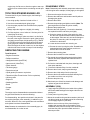
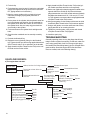
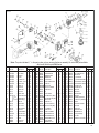
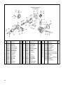
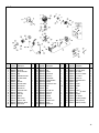
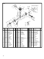
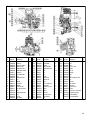
ENGINE
INSTRUCTION
MANUAL
Model:
G-23 Air/Heli/Marine
G-23 Glow
G-38
G-62
G-45
G-445 Twin
VERY IMPORTANT:
FAILURE TO READ AND FOLLOW THESE INSTRUCTIONS
BEFORE YOU PROCEED MAY RESULT IN ENGINE DAMAGE AND THE VOIDING OF YOUR WARRANTY!
INTRODUCTION
Congratulations on purchasing a Zenoah engine. Cared for
properly, these high-quality, finely crafted engines will offer
many years of reliability.
This instruction manual has been developed to ensure optimum performance from the Zenoah engine you have purchased. It’s important that the instructions are read
thoroughly prior to mounting and running the engine.
SAFETY INSTRUCTIONS
This manual describes the engine’s features and functions.
For specific information on mounting, see the instruction
manual included with the model airplane, helicopter, or boat
in which you intend to install the engine.
This model engine will give you considerable pleasure, satisfaction and performance if you strictly follow these safety
instructions and take heed of the warnings as to the engine’s
safe and proper use. Remember at all times, this engine has
more than enough power to cause harm if misused or if the
safety precautions are not observed.
YOU SHOULD ALWAYS:
1. Use genuine parts for replacement.
2. Check the propeller, rotor (helicopter) or screw propeller
(boat) prior to each time the engine is used. If nicked,
scratched, cracked, or damaged in any way, replace it
with a new one.
3. Use the correct size and pitch of propeller for your
engine; refer to the propeller chart in this manual.
4. It is extremely important to balance the propeller prior to
installation of the engine. Failure to do so may cause
damage to the Zenoah engine and/or the airframe.
Securely tighten the propeller nut against the washer
and propeller.
5. Inspect the tightness of the propeller nut prior to each flight.
6. Keep your face and body away from the path of the propeller blades when starting or running your engine.
7. Use a thickly padded glove when hand starting the
engine.
8. Make all carburetor adjustments from behind the propeller.
9. To stop the engine, the black lead wire from the coil
should be grounded to the engine body, or use the
throttle linkage to shut off the air by closing the throttle
valve completely.
DO NOT USE HANDS, FINGERS OR ANY OTHER
PART OF THE BODY TO STOP THE PROPELLER. DO
NOT THROW ANY OBJECT INTO A PROPELLER TO
STOP IT!
2
10. Ensure that all spectators, especially children, are at
least 20 feet away when you start running the engine.
11. Make sure your fuel is kept in a safe place well away
from sparks, heat or anything that could ignite the fuel.
IT IS HIGHLY RECOMMENDED THAT:
1. Safety glasses or goggles be used when starting and
running your engine.
2. You do not run the engine in the vicinity of loose gravel
or sand. The propeller may throw such materials into
your eyes. The engine could also ingest these harmful
materials.
3. Loose clothing should be avoided when operating your
model engine, as it could become entangled in the propeller, creating the possibility of bodily harm. Also, all
loose objects (screwdrivers, pencils, nickel cadmium
glow drivers, etc.) should be removed from your pockets
so that they do not fall into the propeller.
CAUTION:
1. Model engines get very hot while running. Do not
attempt to handle them until they have cooled.
2. Always run your model engines in a well-ventilated
area. Similar to automotive engines, model engines produce harmful carbon monoxide fumes.
3. Never modify the flywheel.
4. Check the flywheel. If it’s damaged, replace it with a
new one.
5. When mixing the fuel or operating the engine, do so in a
well-ventilated area
6. Remember that model engines produce a substantial
amount of power, more than enough to seriously injure
people and/or do considerable damage to property.
Always use common sense, skill and constant observation of safety precautions.
DISASSEMBLY
The Zenoah engine can be disassembled or reassembled without any specific difficulties. Refer to the Engine Maintenance
Section for specific instructions on these procedures. If you
need service to your Zenoah engine, please send your engine
to the authorized service center at the following address:
Horizon Hobby Distributors
Attention: Zenoah Service
4105 Fieldstone Road
Champaign, IL 61822
Phone: (217) 355-9511
ENGINE PARTS IDENTIFICATION
It’s important to be able to identify the parts of your Zenoah
engines. Attached you will find an exploded view of Zenoah
engines, as well as a chart including part numbers and
descriptions. This will assist you in easily and rapidly identifying the respective parts of your Zenoah engine.
SUPPORT EQUIPMENT
The following items, which are not included with your
Zenoah engine, are necessary in order to operate the
model engine.
Fuel—Mix gasoline and 2-stroke oil at a mixing ratio of
25-40:1. Note: Be sure to use a gasoline-resistant fuel tubing
(do not use any silicone rubber tube). Never use any alcohol
fuel or alcohol-added fuel as this will damage the rubber part
of the carburetor. Note: An exception to this is the G-23 Glow
engine, which uses a different carburetor. This engine should
be operated with any high quality two-stroke model airplane
fuel with a Nitro content of between 10-15%.
Propeller—Refer to the Propeller Selection Chart located
on page 8 to determine the best initial propeller for your
particular application.
Manual or Electric Starter—For manual starts, a “chicken
stick” is highly recommended. Never use your fingers to
start any model engine as you could get injured. If you must
hand start a gasoline engine, be sure to protect your hand
with a heavily padded glove. There are a variety of heavyduty electric starters on the market that can be used.
MOUNTING THE ENGINE
Make sure the engine is mounted on the aircraft using aircraft grade plywood that’s at least 6mm in thickness for the
G-23 engine, and 10mm in thickness for the G-38 through
G-445 twin, or a mount of equivalent strength. Make sure
it’s firmly mounted with 4 bolts.
vibration, check the hardness of the rubber, making
sure it’s not too soft, in order to avoid excessive vibration during engine operating rpms. It’s suggested you
note carefully if the engine is vibrating at idle as excessive vibration can result in erratic engine operation due
to overflow at the carburetor.
4. It is suggested you coat the bolts for the muffler with
thread lock (e.g., Blue Thread Locker Z-42 or equivalent) when mounting the muffler to the engine.
BREAK-IN
No specific break-in is required. The engine is gradually
broken-in as it is used, and the output power increases
gradually as the engine breaks in.
OPERATION
STARTING THE ENGINE—AIRCRAFT
Before attempting to start the engine, be sure to read
through all the steps for starting the engine as outlined
below:
Zenoah engines are equipped with the ultra compact C.D.I.
type flywheel magneto ignition system and should be started according to the following procedure:
Note: The magneto system is timed in such a way that
when the compression stroke starts (refer to Figure 1-A)
sparks are never produced on the spark plug, no matter
how fast the propeller is flipped. The correct starting procedure is to quickly flip the propeller when the edge of the
magnet on the rotor is approaching the coil (Figure 1-B).
This means that the propeller should be quickly flipped at
about 90 degrees in crank angle before the compression
stroke is about to start.
Coil
Magnet
Fig 1-A
Note:
1. Be sure to set flat washers or a metal plate on the
reverse side of the mount to prevent the bolts from sinking into the mount. Periodically check the engine mount
for loose bolts.
2. Since the engine is equipped with a float-less carburetor
with a diaphragm pump, the direction of the cylinder
and position of the fuel tank can be freely selected.
3. If the engine is mounted on a shock (rubber) mount
placed between the engine and the firewall for anti-
Fig 1-B
1. Make sure the spark (glow) plug(s) are installed and
tightened. Check the condition of the plug cap for cracks
or breaks.
2. Be sure the propeller is properly secured.
3. Make sure the fuel tank line(s) are properly connected.
The main line should be connected to the carburetor
spray bar.
4. Be certain the mufflers are installed properly.
5. Fill the fuel tank.
6. Choke the engine and turn the propeller through a few
times until the fuel appears at the carburetor.
3
7. Set the throttle valve at the idle position or at the position slightly open from idle.
Red Lead
8. Quickly flip the propeller in a counterclockwise direction
according to the procedure described in the note above.
Black Lead
9. The engine should start after a few flips of the propeller.
10. Be sure to open the choke when the initial firing of the
engine is heard.
11. When the choke is opened, be sure to close the throttle
valve to a position near the idle position before the next
flipping of the propeller is attempted. CAUTION: If the
engine is started when the throttle is wide open, a great
thrusting force will be generated, which can be very
dangerous.
12. If you do not use a chicken stick to start the engine, be
sure to wear a thick glove when flipping the propeller
and use all fingers, except the thumb, for the flipping
operation.
13. Do not over-rev the engine. These engines are designed
to develop maximum output with the standard muffler and
the recommended propeller size. Please refer to the propeller chart on page 8 to confirm the proper propeller for
the applicable Zenoah engine.
Kill Switch
Engine
Body
Ground
CARBURETOR ADJUSTMENT
The carburetor is provided with three adjustment screws,
which are factory set to the best (approximate) positions.
They may need minor adjustment, depending upon the
temperature, humidity, atmospheric pressure (altitude), etc.,
of the area where the engine is being used.
High Speed Needle
Low Speed Needle
STARTING THE ENGINE—HELICOPTER AND
BOAT
1. Fill the tank with fuel
Idle Screw
2. Push the priming bulb located on the carburetor until
fuel appears in the priming bulb (for helicopter).
1. Start the engine without making any adjustments.
3. Choke the engine and open the throttle valve approximately 1/3–1/2 of the full open position.
2. Make adjustments only when the engine shows signs of
inefficient operation.
4. Quickly pull the starter cord until the initial firing of the
engine is heard.
3. Standard settings of each needle is as follows:
a. Low Speed Needle: 11/8 plus/minus 1/4
5. When the initial firing is heard, open the choke, set the
throttle valve at the idle position or at the position slightly open from the idle position and quickly pull the starter
cord a few more times until the engine starts.
Idle Screw: Turning this screw clockwise increases the idling
RPM. Turning it counterclockwise decreases the idling RPM.
6. For helicopter operation, you should adjust the rotorpitch to obtain a 9,000 to 10,000 rpm of the engine at
full throttle operation.
Low Speed Needle: This is the fuel adjust screw (not the air
screw). Turning this needle clockwise makes the gas mixture
leaner, and turning it counterclockwise makes it richer.
HOW TO STOP THE ENGINE
The ability to shut down the engine in an emergency is
extremely important. For stopping the engine, the black
lead wire from the coil should be grounded to the engine
body, or the throttle valve should be closed completely.
Installation of a “stop” or “kill” switch is recommended. Refer
to the example shown in the following diagram.
b. High Speed Needle: 13/8 plus/minus 1/4
High Speed Needle: Turning this needle clockwise makes
the gas mixture leaner, and turning it counterclockwise makes
it richer. Set this needle at a position which is 1/4 open from the
maximum rpm position while the aircraft is on the ground.
Note:
1. Do not tighten the high and low speed needles too
tightly.
2. When the engine has just started and is not warm
enough, there may be insufficient acceleration and the
4
engine may die. Be sure to allow the engine to warm up
at idle for a few minutes before conducting normal operation.
TIPS FOR EXTENDED ENGINE LIFE
To extend the life of your Zenoah engine, the following is
recommended:
DISASSEMBLY STEPS
Note: Disassembly and assembly steps were written using
a G-38 engine as an example, but they apply to all engines.
1. Dismount the engine from the model.
2. Remove the carburetor and insulator carefully without
damaging the gasket.
1. Use a high quality 2-stroke oil mixed at 32 to 1.
3. Remove the muffler.
2. Use the recommended spark (glow) plugs.
4. Remove the spark plug and ignition module. (Note: The
glow engine does not have an ignition module.)
3. Use the proper propeller size and balance the propeller
prior to use.
4. Always adjust the engine to a slightly rich setting.
5. For Glow engines, use an “after-run” oil when you’re finished flying for the day.
6. For long-term storage, make sure there is no fuel left in
the tank or the engine. Remove the spark (glow) plug(s)
and apply several drops of high-quality oil (e.g., Marvel
Air Tool Oil) to the top of the engine and into the spark
(glow) plug hole. Rotate the crankshaft several times.
Store the engine in the box it came in or on the airplane
with the nose down in order to keep oil in the bearings.
SERVICING THE ENGINE
Tools Required:
5. Remove the propeller hub.
6. Remove the rotor (flywheel). If it cannot be detached,
use a plastic hammer and hit the part lightly.
a. Screw the stopper in place of the spark plug, then
turn the rotor counterclockwise until the piston touches the stopper. Take care as it can cause damage to
the piston or connecting rod if the stopper is not
screwed in to the bottom.
b. Loosen and remove the rotor securing nut.
c. Remove the rotor by using the puller. Do not hit the
crankshaft with the plastic hammer, as this can
increase the runout of the shaft.
7. Remove the mounting plate.
8. Remove the four bolts from the crankcase.
• Regular screwdriver
• Phillips screwdriver
/
• Hexagonal wrench (4mm 5/32”)
/
• Open wrench (19mm 3/4”)
9. Tap around the case fitting side gently with the plastic
hammer and slowly separate the crankcase from the
cylinder block.
• Plastic hammer
10. Pull out the crankshaft with the piston, bearings, and
other parts attached.
• Thickness gauge
11. Remove the Woodruff key from the crankshaft.
• Tapered round rod
12. Remove the oil seal, snap ring and bearings.
• Liquid gasket (Permatex or equivalent
13. Remove the circlip and pull out the piston pin.
• Thread lock (Blue Thread Locker Z-42 or equivalent)
14. Remove the thrust washers and needle bearing from
the smaller end of the con rod (G-38).
• Lithium grease
• Engine oil
• Washing gasoline
• Brush
• Scraper
• Cloth
The engine can be disassembled or reassembled without
any specific difficulties, but note the following:
For disassembling, the special tools shown in the parts list
are required (stopper, puller assembly), in addition to general tools. Be sure to use a new gasket when the crankcase
and cylinder have been disassembled.
Note: Because the crankshaft is of the assembly type, do
not disassemble, hit or twist its end.
15. Remove the piston ring.
16. Wash each part. Check for abrasion and damage, and
replace any part that is defective.
ASSEMBLY (G-38)
1. Apply engine oil (SAE #30) to the inside of the cylinder
and to the needle bearings on the larger end of the connecting rod.
2. Fit the piston ring to the piston.
3. Mount the needle bearing and thrust washer (with its oil
slot facing inside) to the smaller end of the connecting
rod and apply engine oil (SAE #30).
4. With the arrow on the top of the piston facing the
straight side (opposite side to the propeller) of the
crankshaft, fit the piston to the top of the connecting rod
and insert the piston pin with its blank end to the
exhaust port side.
5
5. Fit the circlip.
6. Fit the bearings, snap ring and oil seal to the crankshaft.
(Apply lithium grease to the lip area of the oil seal and
fit it, paying attention to its direction.)
7. Wipe the contact surfaces of the cylinder block and
crankcase, and apply liquid gasket (Permatex or
equivalent).
8. Put the piston in the cylinder, with the piston’s arrow facing in the exhaust port direction. Set the crankshaft to
the cylinder block. When this is done, fit the oil seal to
the cylinder block. Also, the snap ring joint should be
set vertically to the cylinder.
9. Fit the crankcase to the cylinder block and tighten the
bolts.
10. Check that the crankshaft can be smoothly turned by
hand.
11. Put back the Woodruff key.
12. Replace the rotor (flywheel), fitting it to the Woodruff
key. Tighten the hub nut after having applied thread lock
(Blue Thread Locker Z-42 or equivalent) to the threads.
13. Apply thread lock (Blue Thread Locker Z-42) to the muffler bolts and mount the muffler.
14. Apply thread lock (Blue Thread Locker Z-42) to the ignition module set screws and fix the coil temporarily.
15. Set the rotor (flywheel) so that the magnet is located on the
opposite side of the module (G-38). Place a thickness
gauge between the core of the module and rotor (flywheel)
and adjust the clearance to 0.25 ^ 0.35 mm (0.01 ^ 0.014
in). Then tighten the set screws after having applied thread
lock (Blue Thread Locker Z-42) to them.
16. Using a new gasket, fix the insulator with screws to which
thread lock (Blue Thread Locker Z-42) has been applied.
17. Using a new gasket, mount the carburetor with screws,
paying attention to its mounting direction.
18. Tighten the mounting plate, using screws with thread
lock (Blue Thread Locker Z-42) applied.
19. Install the spark plug.
TROUBLESHOOTING
Generally speaking, there are very few things that will keep
today’s modern engines from starting. To that end, make sure
you’re using good quality “fresh” fuel, that good glow plugs
are installed, and the starting battery (glow) is charged and in
good condition. Should the engine fail to start after these
items are verified, refer to the following chart(s):
GASOLINE ENGINES:
a) The engine does not start.
The crankshaft
does not rotate
Seizure, intrusion of a foreign substance
The crankshaft
rotates
The fuel has not been fed to the
carburetor
Disassemble and repair
Clogging inside the
carburetor
Disassemble and clean
Clogging of the fuel
piping
Clean
The fuel has been fed to the
carburetor
No compression
(normally 7 kg/cm2
99.5 psi or more)
Compression adequate
The spark plug does not spark
The STOP switch has
Turn ON
been turned OFF
Wiring is disconnected
Repair
The spark plug is defective
Replace
The ignition module is defective Replace
The air gap is too large
Adjust
The spark plug gap is too large
Adjust
6
Loosened
Tighten further
spark plug
Replace
Abrasion or damage of
the cylinder, piston, or
piston ring
The spark plug does spark
Remove the spark
plug and dry it
The carburetor has
not been properly
Readjust
adjusted
The fuel is not
Replace
suitable
Wet plug
b) The engine stops by itself
The crankshaft does not rotate
or is abnormally heavy
It suddenly stops
The crankshaft
rotates
It slows down and stops
c) Lower power output
Out of fuel
Not out of fuel
See a)
Put back
The plug cap has come off
Wiring disconnection
Spark plug bridge
Repair
Use a standard plug
Use clean fuel
The STOP switch has
been turned off
Turn ON
Refuel
The fuel is not fed to the carburetor
Water is mixed in the fuel
See a)
Replace
The carburetor has not beeen properly adjusted
Air suction from a carburetor joint or oil seal
Abrasion of the piston ring
The fuel is not suitable
Overheating
Clogging of the muffler or exhaust port due to carbon
The spark plug heat range is not proper
d) The engine does not stop
See c)
Overheating
Repair
The STOP switch is defective
Repair
Switch wiring is disconnected
Readjust
Repair
Replace
Replace
Clean
Replace
GLOW ENGINE:
SYMPTOM
CAUSE
CORRECTIVE ACTION
Engine fails to Start
Low voltage on
starting battery (glow)
Replace/recharge the starting battery (glow)
Bad glow plug(s)
Inspect/replace bad glow plugs
Insufficient priming
Repeat priming procedure
“Flooded” due to
excessive priming
Disconnect battery, remove glow plugs (glow
only) and rotate propeller several times to
“clear” cylinder(s)
Engine fires but
does not run
Over primed
Disconnect battery (glow) and rotate
propeller several times to “clear”
cylinder(s)
Engine starts but slows
down and then stops
Mixture too rich
Close high speed needle valve
1/2 turn and start again. Repeat until
engine is running smoothly.
Engine starts, speeds up,
and then quits
Mixture too lean
Open high speed needle valve
1/2 turn and start again. Repeat until
engine is running smoothly.
Engine quits when starter
battery is removed
Mixture too rich
Close high speed needle valve
1/2 turn and restart.
Incorrect glow plugs
Change glow plugs
Incorrect or bad fuel
Change fuel
7
In the event that none of the above procedures results in
the engine running properly, contact our service department for suggestions at:
PROPELLER CHART
Horizon Hobby Distributors
4105 Fieldstone Road
Champaign, IL 61922
Phone: 217-355-9511 (Mon-Fri 8:00-5:00 CST)
Engine
Note: All recommendations are based on engines using APC
brand props.
G-23A
G-23 Glow
G-23 Heli
PROPELLER SELECTION
In the chart at right you’ll find a propeller selection list. This
chart enables you to select the best propeller for initial setup of your Zenoah engine.
Remember, it’s imperative to balance each propeller prior to
installation onto your Zenoah engine. Failure to do so may
cause unwanted vibration in your aircraft.
G-23 Marine
G-38 Gas
G-45 Gas
G-62 Gas
G-445 Gas
15x8 @ 9,000
17x8 @ 7,200
Adjust pitch of rotor to obtain
9,000–10,000 rpm of the
engine at full throttle
Diameter = 65–75mm
Pitch ratio 1.9–1.4mm*
18x10 @ 7,300
20x10 @ 7,200
22x10 @ 7,200
22x12 @ 7,200
24x10 @ 7,200
CONSUMER WARRANTY AND REPAIR
ENGINE SPECIFICATIONS
OUTSIDE DIMENSIONS (MM)
Items
G-23
G-23 GLOW
G-23 HELI
G-23 MARINE
G-38
G-45
G-62
G-445
Length
139mm
139mm
142mm
142mm
Width
105mm
105mm
105mm
105mm
Height
179mm
179mm
179mm
179mm
170mm
152mm
162.5mm
191.5mm
130mm
130mm
140mm
257mm
215mm
185mm
185mm
190mm
Operating
RPM
Optional
Mufflers
2,000–10,000
2,000–10,000
3,000–11,000
3,500–15,000
2,000–9,000
2,000–10,000
2,000–10,000
1800–10,000
BIS07123
BIS07123
—
—
BIS07138
BIS07145
BIS07163
BIS07445/6
SPECIFICATIONS
8
Displacement
(cu. in.)
G-23
1.4
G-23 Glow
1.4
G-38
2.3
G-45
2.74
G-62
3.8
G-445
4.52
Bore
(cu. in.)
1.3
1.3
1.5
1.69
1.9
1.5x2
Stroke
(cu. in.)
1.1
1.1
1.3
1.22
1.4
1.2x2
Weight
(oz.)
51
37
67
74
73
108
K
(ISO)
M8x1.25/6x1
M8x1.25
M10x1.25
8x1
10x1
—
HP
(H/M)
2.0
2.5
2.2
3.3
4.75
6
Carb
(walboro)
WA197A/WA167A
—
WT338/WTA-6A
HDA-48D
HDA-48D
WJ-64
G-23
Note: The parts indicated “*” in the part number column are supplied as an assembly. No individual part available.
A=Aircraft, H=Helicopter, M=Marine
Index
No. Parts No.
Description
A, H CYLINDER
1 ZEN2301
M CYLINDER
2 ZEN2302M
M JACKET
3 ZEN2303M
M JOINT
4 ZEN2304M
M O RING 3X38
5 ZEN2305M
M O RING 1.5X19.5
6 ZEN2306M
M BOLT M3X8
7 ZEN2307M
8 ZEN2308
GASKET CYL
9 ZEN2309
BOLT M5X20
10 ZEN2310
GASKET INSU
11 ZEN2311
INSULATOR
12 ZEN2312
GASKET CARB
ZEN2314 Note: CRANKCASE COMP
as CRANKCASE (R)
13
* sold
an
14
* assembly CRANKCASE (F)
15 ZEN6213
CASE PIN
16 ZEN2316
GASKET CASE
17 ZEN2317
SEAL 12X22X7
18 ZEN2318
SHAFT BEARING
19 ZEN2319
RING SNAP
20 ZEN2320
SEALED BEARING
21 ZEN2321M
FRONT OIL SEAL
22 ZEN2322
CASE BOLT M5X30
23 ZEN2323
PISTON
24 ZEN2324
PISTON RING
25 ZEN2325
PISTON PIN
}
Q’ty per unit
Q’ty per unit Index
No.
Parts
No.
Description
PU PUH PUM
PU PUH PUM
26 ZEN2326 PIN RETAINER
2 2 2
1 1 0
27 ZEN2327 CONROD BEARING
1 1 1
0 0 1
28 ZEN2328 CONROD SPACER
2 2 2
0 0 1
29 ZEN2329 CRANKSHAFT
1 1 1
0 0 2
30 ZEN2330 PLATE MOUNT
1 1 1
0 0 1
31 ZEN2331 MOUNT SCREW CM5X6 3 3 3
0 0 1
32 ZEN2332 ROTOR NUT
1 0 0
0 0 2
33 ZEN2333M H, M PULLEY
0 1 1
1 1 1
34 ZEN2334M H, M PULL STARTER
0 1 1
4 4 4
35 ZEN2341 SCREW M4X14
0 4 4
1 1 1
36 ZEN6227 KEY
1 1 1
1 1 1
37 ZEN2337 SHAFT SPACER
0~2 0~2 0~2
1 2 1
38 ZEN6236 A SOURCE COIL (GRAY) 1 0 0
1 1 1
39 ZEN2339M H, M SOURCE COIL (RED) 0 1 1
1 1 1
40 ZEN6237 IGNITION COIL
1 1 1
1 1 1
41 ZEN2341 SCREW M4X14
2 2 2
3 3 3
42 ZEN6238 A PLUG CAP (BLACK)
1 0 0
1 1 1
43 ZEN2343M H, M PLUG CAP (RED) 0 1 1
1 1 1
44 ZEN6239 PLUG SPRING
1 1 1
2 2 2
45 ZEN6241 SCREW M4X22
2 2 2
1 1 1
46 ZEN2346 SPARK PLUG BMR74
1 1 1
1 1 0
2 0 2
47 ZEN2347 CARB SCREW M5X50
0 0 1
48 ZEN2348H CARB SCREW M5X55
0 2 0
4 4 4
49 ZEN2349 CARB WASHER 5X10X1.6 2 0 2
1 1 1
50 ZEN2350H H AIR CLEANER
0 1 0
2 2 2
1 0 0
51 ZEN2351 CARBURETOR 197A
1 1 1
Index
No. Parts No. Description
52 ZEN2352M CARBURETOR 167A
53 ZEN2353 INSU SCREW M5X20
54 ZEN2354 NEW ROTOR
55 ZEN2355 A, H MUFFLER
56 ZEN2356 A, H MUFFLER GASKET
57-1 ZEN2357 A MUFFLER BOLT M5X50
57-2 ZEN2357H H MUFFLER BOLT M5X60
58-1 ZEN2358 A SCREW M4X8
58-2 ZEN2358H H SCREW M4X16
59 ZEN2359 PROP HUB
60 ZEN2360 PROP STUD
61 ZEN2361 PROP WASHER
62 ZEN2362 PROP NUT
63 ZEN6252 STOPPER (OPTIONAL)
64 ZEN6251 PULLER ASS’Y (OPTIONAL)
65 ZEN2365 SOCKET
66 ZEN2366 H MUFFLER SPACER
67 ZEN2367 H SPACER
ZEN2370 GASKET SET
ZEN2371 SCREW/NUT SET
ZEN2372 CARB REPAIR KIT
ZEN2384 STUD (MUFFLER)
ZEN2392 TOOL SET
ZEN2395 MARINE CLUTCH ASS’Y
Q’ty per unit
PU PUH PUM
0
2
1
1
1
2
0
1
0
1
1
1
1
1
1
1
0
0
1
1
1
1
1
1
1
2
1
1
2
0
2
0
1
0
0
0
0
1
1
1
1
1
1
1
1
1
1
1
1
2
1
0
0
0
0
0
0
0
0
0
0
1
1
1
0
0
1
1
1
1
1
1
9
G-38
(Standard Accessory
for G380PU)
Index
No.
1
2
3
4
5
6
11
12
13
14
15
16
17
18
19
20
10
Parts No. Description
ZEN3801 CYLINDER
ZEN3802 INSULATOR
ZEN3803 CARB GASKET
ZEN3804 INSULATOR SCREW
ZEN3805 INSULATOR GASKET
ZEN3806 MUFFLER ASS’Y
ZEN3811 MUFFLER GASKET
ZEN3812 MUFFLER BOLT
ZEN3813 CRANKCASE
ZEN3814 CASE BOLT
ZEN3815 CASE WASHER
ZEN3816 CASE PLUG
ZEN3817 PLUG GASKET
ZEN3818 PISTON
ZEN3819 PISTON RING
ZEN3820 PISTON PIN
Q’ty/
unit
1
1
1
2
1
1
1
2
1
4
4
1
1
1
1
1
Index
No.
21
22
23
24
25
26
27
28
29
30
31
32
33
34
35
36
Parts No.
ZEN3821
ZEN3822
ZEN3823
ZEN3824
ZEN3825
ZEN3826
ZEN3827
ZEN3828
ZEN3829
ZEN3830
ZEN3831
ZEN3832
ZEN3833
ZEN3834
ZEN3835
ZEN3836
Description
PIN RETAINER
CONROD SPACER
CONROD BEARING
CRANKSHAFT
CRANKSHAFT BEARING
FRONT OIL SEAL
SNAP RING
REAR OIL SEAL
KEY
ROTOR NUT
LOCK WASHER
ROTOR WASHER
PROP HUB (NEW)
HUB BOLT
PROP WASHER (NEW)
PROP BOLT (NEW)
Q’ty/
unit
2
2
1
1
2
1
1
1
1
1
1
1
1
2
1
2
Index
No.
37
38
39
40
41
42
43
44-1
44-2
45
46
47
Parts No. Description
ZEN3837 MODULE
ZEN3838 ROTOR (NEW)
ZEN3839 SPACER (MODULE)
ZEN6238 PLUG CAP (BLACK)
ZEN6239 CAP SPRING
ZEN6242 SPARK PLUG, C859
ZEN3843 MODULE BOLT
ZEN3844 CARB ASS’Y (HT-338) W/CHOKE
ZEN3850 CARB ASS’Y (WTA-6) W/O CHOKE
ZEN3845 CARB SCREW
ZEN3846 MOUNT
for G380PU
ZEN3847 MOUNTING BOLT
ZEN3870 GASKET SET
ZEN3871 SCREW/NUT SET
}
Q’ty/
unit
1
1
3
1
1
1
3
1
1
2
1
4
1
1
G-45
Index
No.
1
2
3
4
5
6
7
8
9
10
11
13
14
15
16
17
18
19
20
Parts No.
ZEN4501
ZEN4502
ZEN4503
ZEN4504
ZEN6204
ZEN4506
ZEN4504
ZEN6207
ZEN6208
ZEN6209
ZEN6210
ZEN4513
ZEN6213
ZEN6214
ZEN6215
ZEN6216
ZEN6217
ZEN6276
ZEN4520
Description
CYLINDER
INSULATOR
INSULATOR GASKET
BOLT
CARBURETOR GASKET
CYLINDER GASKET
BOLT
MUFFLER
MUFFLER GASKET
MUFFLER BOLT
MUFFLER NUT
CRANKCASE COMP.
CASE PIN
SNAP RING
BEARING
REAR OIL SEAL
FRONT OIL SEAL
ELBOW FUEL NIPPLE
CASE GASKET
Q’ty/
unit
1
1
1
2
1
1
4
1
1
2
2
1
3
1
2
1
1
1
1
Index
No.
21
22
23
24
25
26
27
28
29
30
31
32
33
34
35
36
37
38
39
Parts No. Description
ZEN4504 BOLT
ZEN4522 PIPE
ZEN4523 PISTON
ZEN4524 PISTON RING
ZEN4525 PISTON PIN
ZEN6223 PIN RETAINER
ZEN6224 CONROD BEARING
ZEN4528 WASHER
ZEN4529 CRANKSHAFT COMP.
ZEN6228 SHIM
ZEN6227 KEY
ZEN6229 FLYWHEEL NUT
ZEN6230 PROP HUB
ZEN6232 HUB BOLT
ZEN6233 WASHER
ZEN6234 PROP BOLT
ZEN6257 MAGNETO ASS’Y
ZEN6235 ROTOR
ZEN6236 SOURCE COIL
Q’ty/
unit
4
1
1
2
1
2
1
2
1
0-2
1
1
1
2
1
1
1
1
1
Index
No.
40
41
42
43
44
45
46
47
48
49
50
51
52
53
54
55
56
57
Parts No. Description
ZEN6237 IGNITION COIL
ZEN6238 PLUG CAP (BLACK)
ZEN6239 CAP SPRING
ZEN4543 SOURCE COIL SCREW
ZEN6241 COIL SCREW
ZEN6242 SPARK PLUG
ZEN6243 CARBURETOR ASS’Y
ZEN4547 BOLT
ZEN6245 WASHER
ZEN6246 WASHER
ZEN6247 BOLT
ZEN6248 MOUNT
*for G450PU
ZEN6249 BOLT
ZEN6250 WASHER
ZEN6251 PULLER ASS’Y
ZEN6252 STOPPER (OPTIONAL)
ZEN6253 GUIDE (OPTIONAL)
ZEN4557 WRENCH (OPTIONAL)
}
Q’ty/
unit
1
1
1
2
2
1
1
2
2
2
1
1
4
4
1
1
1
1
11
G-62
* (Accessory for G620PU-1)
Index
No.
1
2
3
4
5
6
7
8
9
10
11,12
13
14
15
16
17
18
19
20
12
Parts No. Description
ZEN6201 CYLINDER
ZEN6202 INSULATOR GASKET
ZEN6203 INSULATOR
ZEN6204 CARBURETOR GASKET
ZEN6205 CYLINDER BASE GASKET
ZEN2309 CYLINDER BOLT
ZEN6207 MUFFLER
ZEN6208 MUFFLER GASKET
ZEN6209 MUFFLER BOLT
ZEN6210 MUFFLER NUT
ZEN6211 CRANKCASE COMP.
ZEN6213 CASE PIN
ZEN6214 SNAP RING
ZEN6215 BEARING
ZEN6216 REAR OIL SEAL
ZEN6217 FRONT OIL SEAL
ZEN6218 CRANKCASE GASKET
ZEN6219 CASE ASS’Y BOLT
ZEN6220 PISTON
Q’ty/
unit
1
1
1
1
1
4
1
1
2
2
1
3
1
2
1
1
1
4
1
Q’ty/
Index
Q’ty/ Index
unit
No. Parts No. Description
unit No. Parts No. Description
21 ZEN6221 PISTON RING
4
40 ZEN6240 IGNITION COIL SCREW
2
22 ZEN6222 PISTON PIN
1
41 ZEN6241 SOURCE COIL SCREW
2
23 ZEN6223 PIN RETAINER
1
42 ZEN6242 SPARK PLUG, C859
1
24 ZEN6224 NEEDLE BEARING
2
43 ZEN6243 CARBURETOR ASS’Y
1
25 ZEN6225 CONROD SPACER
1
44 ZEN6244 CARB MOUNT SCREW
2
26 ZEN6226 CRANKSHAFT COMP.
2
45 ZEN6245 CARB WASHER
2
27 ZEN6227 KEY
1
46 ZEN6246 WASHER
2
28 ZEN6228 SHIM
2
47 ZEN6247 TAP PROP BOLT
1
29 ZEN6229 FLYWHEEL NUT
1
48 ZEN6248 MOUNT
1
*for G62PU
30 ZEN6230 PROPELLER COMP. FOR G620PU-1 HUB 0-2
49 ZEN6249 BOLT
4
31 ZEN44553 PIN FOR G620PU-1
1
50 ZEN6250 WASHER
4
32 ZEN6232 HUB BOLT
1
51 ZEN6251 PULLER ASS’Y
1
33 ZEN6233 PROP WASHER
2
52 ZEN6252 STOPPER (OPTIONAL)
1
34 ZEN6234 PROP BOLT
1
53 ZEN6253 PISTON PIN GUIDE (OPTIONAL) 1
ZEN6200 SPRING STARTER
35 ZEN6235 ROTOR
1
1
ZEN6255 HI-SPEED NEEDLE
36 ZEN6236 SOURCE COIL
1
1
ZEN6256 LO-SPEED NEEDLE
37 ZEN6237 IGNITION COIL
1
1
ZEN6257 MAGNETO ASS’Y
38 ZEN6238 PLUG CAP (BLACK)
1
1
39 ZEN6239 PLUG CAP SPRING
1
}
G-445
Index
No.
1
2
3
4
5
6
7
8
9
10
11
12
13
14
15
16
17
18
19
20
21
Parts No.
ZEN44501
ZEN44502
ZEN44503
ZEN44504
ZEN44505
ZEN44506
ZEN4547
ZEN44508
ZEN44509
ZEN44510
ZEN6213
ZEN6215
ZEN6214
ZEN44514
ZEN6217
ZEN6276
ZEN44517
ZEN44518
ZEN44509
ZEN44520
ZEN44521
Description
CYLINDER
MANIFOLD
MANIFOLD GASKET
MANIFOLD BOLT
CARBURETOR ASS’Y
CARBURETOR GASKET
CARB BOLT
CYLINDER GASKET
BOLT
CRANKCASE ASS’Y
PIN
BEARING
SNAP RING
BEARING
FRONT OIL SEAL
FUEL NIPPLE ELBOW
PIPE
CRANKCASE GASKET
BOLT
PISTON
PISTON RING
Q’ty/
unit
2
1
2
4
1
1
2
2
8
1
4
2
2
1
1
1
1
1
4
2
4
Index
No.
22
23
24
25
26
27
28
29
30
31
32
33
34
35
36
37
38
39
40
41
42
Parts No.
ZEN44522
ZEN44523
ZEN44524
ZEN44525
ZEN44526
ZEN6228
ZEN6227
ZEN6229
ZEN6235
ZEN6236
ZEN6238
ZEN44533
ZEN6238
ZEN6239
ZEN6242
ZEN44537
ZEN44538
ZEN44539
ZEN44540
ZEN6209
ZEN44542
Description
PISTON PIN
PIN RETAINER
BEARING
THRUST WASHER
CRANKSHAFT COMP
SHIM
KEY
NUT
ROTOR
SOURCE COIL
IGNITION COIL
CORD
PLUG CAP (BLACK)
CAP SPRING
SPARK PLUG, C859
SCREW
SCREW
MUFFLER
MUFFLER GASLET
MUFFLER BOLT
NUT
Q’ty/
unit
2
4
2
4
1
0-2
1
1
1
1
2
1
2
2
2
4
2
2
2
4
Index
No.
43
44
45
46
47
48
49
50
51
52
53
54
55
56
57
58
59
60
Parts No. Description
ZEN44543 MOUNT
ZEN44544 BOLT
ZEN44545 BOSS
ZEN44546 CLUTCH COMP
ZEN44547 SPRING
ZEN44548 COLLAR
ZEN44549 WASHER
ZEN44550 BOLT
ZEN44551 PAD
ZEN44552 HUB. PROPELLER COMP
ZEN44553 PIN
ZEN6232 HUB BOLT
ZEN6233 HUB WASHER
ZEN6234 PROP BOLT
ZEN6247 TAP PROP BOLT
ZEN44555 SOCKET
ZEN6251 PULLER ASS’Y (OPTIONAL)
ZEN44554 STOPPER (OPTIONAL)
ZEN44556 HI-SPEED NEEDLE
ZEN44557 LOW-SPEED NEEDLE
Q’ty/
unit
1
3
1
1
1
1
1
1
1
1
2
2
1
1
1
1
1
1
1
1
13
POLICY
Zenoah engines are guaranteed against workmanship and
manufacturing defects for a period of 3 years from the original date of purchase. This warranty is limited to the original
purchaser of the engine and is not transferable.
Warranty repairs will NOT cover:
1. Include complete name and address information inside
the carton, as well as clearly writing it on the outer
label/return address area.
2. Include a note containing a brief summary of the difficulty and include the following information:
• Nitro content and brand of fuel (glow engine only)
• Propeller size and brand used
1. Normal engine wear
• Type of spark (glow) plug used
2. Damage due to insufficient maintenance
• Type of engine mount
3. Damage related to over-revving of the engine due to
small prop size or unreasonable use
• Approximately how much running time the engine had
before difficulty
4. Rusted bearings
5. Crash damage
3. Date your correspondence and be sure your name and
address appear on this enclosure.
6. Damage due to use of improper fuel and/or spark (glow)
plug
4. Include a phone number where you can be reached
during the business day.
7. Damage due to lean runs, such as rusted bearings,
seized connecting rod or piston, etc.
8. Damage caused by foreign objects (dirt or broken glow
plug filaments)
9. Damage caused by unreasonable mounting or running
conditions (dust, insufficient cooling, improper mounting, improper propeller size of lack of balancing, etc.)
10. Damage due to improper disassembly
11. Modifications of any kind
If your engine needs repair, please do the following:
Ship your engine in its original box, freight prepaid to:
Horizon Service Center
Attn: Zenoah Service
4105 Fieldstone Road
Champaign, IL 61822
Phone: (217) 355-9511
Note: Do not use the engine’s original box as the shipping
box. Rather, package this box inside a sturdy shipping box.
14
WARRANTY REPAIRS
To receive warranty service you must include your original
dated sales receipt to verify your proof-of-purchase date.
Providing that warranty conditions have been met, your
engine will be repaired without charge.
NON-WARRANTY REPAIRS
Should your repair cost exceed 50% of the retail purchase
cost, you will be provided with an estimate advising you of
your options. Any return freight for non-warranty repairs will
be billed to the consumer.
We accept both Visa and MasterCard for payment. Please
include your card number and expiration date.
The Consumer Warranty Registration below must be completely filled out and mailed to:
Horizon Service Center
Attn: Zenoah Warranty
4105 Fieldstone Road
Champaign, IL 61822
CONSUMER WARRANTY REGISTRATION
Fill in and mail this form along with your dated sales receipt (send a copy, keep the original for your files) within 10 days of
purchase to:
Horizon Service Center
Attn: Zenoah Warranty Dept.
4105 Fieldstone Road
Champaign, IL 61822
Engine Type: _____________________________________________________________________________________
Date of Purchase: _________________________________________________________________________________
Owner’s Name: ___________________________________________________________________________________
Street Address: ___________________________________________________________________________________
City/State/Zip: ____________________________________________________________________________________
Daytime Phone Number: ____________________________________________________________________________
Purchased From: __________________________________________________________________________________
Dealer’s Name: ___________________________________________________________________________________
Street Address: ___________________________________________________________________________________
City/State/Zip: ____________________________________________________________________________________
Please cut on dotted line.
15
© Copyright 1999, Horizon Hobby Distributors, Inc.
www.horizonhobby.com