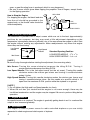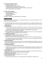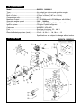
1
848H4893A3 (704) OWNER’S MANUAL MODEL: G620PU G620PU-1 WARNING 警 告 • Do not modify any parts of the engine. • This engine is designed to be used to Radio controlled products. • In case any modification by customer, ZENOAH shall not bear any responsibility from the damage caused by such modification. • Keep ignition system well maintained. ● この製品はラジオコントロール 飛行機用に設計されています。 ● 改造、組み替えされて使用され た場合当社は一切の責任を負い ません。 ● 特に電装品は常に点検、整備し てご使用ください。 April 2007 1. Safety Precautions • This manual describes the engine. For its mounting and control, see the instruction manual for a model plane. • This engine is designed for use on the model plane. If it is used for any other purpose, we cannot be responsible for its reliability or safety. • Use genuine parts for replacement. • Check the propeller every time. If it is damaged replace it with a new one. • If the propeller hits something while the engine is in operation, immediately stop the engine and check it. • Start the engine on flat surface without pebble stones. • Never modify the flywheel. • Check the flywheel. If it is damaged, replace it with a new one. • When mixing the fuel, or operating the engine, carry it out in a well-ventilated place. 2. Mounting Make sure that the engine is mounted on the aircraft grade plywood with more than 10mm of thickness or a mount of equivalent strength and is firmly fixed with 4 bolts. [ NOTE ] 1. Be sure to set flat washers or metal plate on the reverse side of the mount to prevent bolts from sinking into the mount. Before flying the air-plane, be sure to check for loose bolts. 2. The mounting bolts should be screwed into the crankcase within 8 ~ 12 mm of depth. 3. Since this engine is equipped with a float-less carburetor with a diaphragm pump, the direction of cylinder and position of fuel tank can be freely selected. 3. Propeller 1. Recommended prop size. The recommended prop sizes are as shown in the table bellow. Diameter x Pitch (in.) 22 x 6 ~ 8, 20 x 7 ~ 10, 18 x 8 ~ 12 This engine produces the maximum output when the engine is running at about 8,500rpm. Be sure to use a propeller which makes the engine speed approximately 7,000 ~ 9,000rpm while the airplane is flying. When using a propeller of small diameter, a light weight propeller is not suitable. 2. There are two types of propeller mounting bolts; L=45 and L=50. Select the proper type of bolt depending on the thickness of propeller used and the use of the spinner. [ NOTE ] 1. When mounting a thin propeller, cut off the end of bolt or add a flat washer. 2. When mounting the spinner, set a pin on the hub with more than 3 mm of diameter, thus preventing slipping. 4. Fuel Mix gasoline and 2-stroke oil at a mixing ratio of 25 ~ 40 :1. 2 [ NOTE ] 1. Be sure to use a gasoline-resistant fuel piping. (Do not use any silicon rubber tube). 2. Never use any alcohol fuel or alcohol added fuel, or the rubber part in the carburetor will be damaged. 5. Operation Hand flip start Since the engine is equipped with the ultra compact C.D.I. type flywheel magneto ignition system, it should be started according to the following procedure; ✽ The magneto system of the engine is designed in such a way that when the exhaust port is closed by the piston, that is, when the compression stroke starts (Refer to Fig.1-A), sparks are never produced on spark plug no matter how fast the propeller may be flipped. Be sure to quickly flip the propeller when the edge of magnet on the rotor is approaching the coil (Fig.1-B). It means that the propeller should be quickly flipped about 90 degrees in crank angle before the compression is about to start. Coil Fig.1 Magnet A B ✽ Because of the above conditions the propeller should be mounted to the hub as shown in (Fig. 2) and quickly flipped within the range of about 180˚ from the horizontal position. Fig.2 The cut portions of propeller mount and the propeller should be set in the same direction. Cut portion [ NOTE ] When the engine is mounted so the cylinder is kept horizontal, the propeller should be set at a different angle of 90˚. How to Start the Engine 1. Fill the fuel tank with the fuel. 2. Close the choke valve and open the throttle valve approximately 1/3 ~ 1/2 of the full open position. 3. Quickly flip the propeller in the counterclockwise direction according to the procedure described above. When flipped several times, the sound (popping sound) of initial explosion is heard. 4. When the initial explosion is heard, open the choke valve, set the throttle valve at the idle position or at the position slightly open from the idle position and flip the propeller a few more times. Then, the engine starts. [ NOTE ] • Be sure to open the choke when the initial explosion is heard. • When the choke is opened, be sure to close the throttle valve to a position near the idle position before starting the next flipping (If the engine is started while the throttle is wide 3 open, a great thrusting force is produced, which is very dangerous). • Be sure to wear a thick glove when flipping the propeller. Use all fingers, except thumb, for the flipping operation. How to Stop the Engine For stopping the engine, the black lead wire from the coil should be grounded to the engine body, or the throttle valve should be closed completely. RED LEAD BLACK LEAD KILL SWITCH ENGINE BODY EARTH 6. Carburetor Adjustment The carburetor is provided with 3 adjust screws which are set to the best (approximately) positions by our company, but they may need a little adjustment depending on the temperature, atmospheric pressure (altitude), etc. of the area where the engine is used. Start the engine without making any adjustments. Make readjustments only when the engine shows any mal-functioning. Low Speed Needle Idle Screw High Speed Needle Standard Opening Position : LOW SPEED NEEDLE : 11/2 ± 1/4 HIGH SPEED NEEDLE : 11/4 ± 1/4 [ NOTE ] Be sure to stop the engine before starting the adjustment, thus ensuring safety. Idle Screw: Turning this screw clockwise increases the idling R.P.M. Turning it counterclockwise decreases the idling R.P.M. Low Speed Needle: This is the fuel adjust screw (not the air screw). Turning this needle clockwise makes the mixture gas leaner and turning it counterclockwise makes it richer. High Speed Needle: Turning this needle clockwise makes the mixture gas leaner and turning it counterclockwise richer. Set this needle at a position which is 1/4 open from the maximum R.P.M. position while the airplane is on ground. [ NOTE ] 1. Do not tighten the High and Low Speed needles too firmly. 2. When the unit has just started and the engine is not warm enough, there may be insufficient acceleration and the engine may be stopped. Be sure to perform idling before operation. 7. Engine Break-in No specific break-in is required. The engine is gradually getting break-in as it is used and the output is also increased gradually. 8. Maintenance This engine is used for power source for radio controlled airplane so you are strictly requested to check engine and relative parts of airplane. 4 1) Daily check (before starting) • Leakage, damage, crack • Muffler fixing bolts (torque, crack) • Propeller hub (transformation, fixing bolts/nut) (P/N: 2629-51410 or 2629-91510, 3544-11510 and 1100-43231) • Rotor (transformation, play, airgap) 2) Every 25 hours check • Spark plug (gap, cleaning) • Cylinder (abrasion) • Piston/Ring (abrasion) • Bearing (Gritty) According to the checks, replace any part if necessary. 9. Servicing The engine can be disassembled or reassembled without any specific difficulties, but be careful of the following matters; a. For disassembling, the special tools shown in the parts list are required in addition to the general tools. Be sure to use a new gasket when the crankcase and cylinder have been disassembled. b. Removing rotor 1. Screw in the stopper (P/N:3350-96220) in place of the spark plug. Then turn the rotor counterclockwise until the piston touches the stopper. Take care it can cause damage to the piston or connecting rod if the stopper is not screwed in to the bottom. 2. Loosen and remove the rotor securing nut. 3. Remove the rotor by using the puller (P/N:1490-96101). Do not hit on the crankshaft by a hammer, that can increase the runout of the shaft. c. Assembling crankcase 1. Apply grease on the oil seal lips and oil on the bearing. 2. Assemble the crankshaft with a new gasket. 3. When both front and rear crankcases are tightened, the portion of gasket protruding on the cylinder mounted surface should be cut off with a knife until the gasket becomes flush with the cylinder mounted surface. d. Assembling piston Before assembling the piston, apply the oil on the small end bearing and piston, and set the piston ensuring that the arrow mark on the top of piston is directed toward the direction of exhaust port. e. Assembling cylinder 1. Coat the oil on the inner surface of cylinder. 2. The piston is provided with a knock pin which stops the piston ring from turning. Set the splitted section of piston ring at the knock pin and assemble the cylinder ensuring not to break the piston ring. f. Assembling rotor Make sure to put lock tight (Medium strength type: TreeBond 1322N, LOCTITE 242,243, PACER ZAP Z-42) on the rotor fixing nut (P/N:1100-43231). g. Adjusting air gap of coil. The air gap of coil should be adjusted to 0.3 mm (0.01"). h. Adjusting ignition time. This engine with the point-less C.D.I. type requires no adjustments of ignition time. 5 10. Specifications Model ......................................................G620PU · G620PU-1 Type .........................................................Air cooled two stroke cycle gasoline engine Displacement ...........................................62.0cc (3.78cu. in) Bore x Stroke ...........................................47.5mm x 35mm (1.87 in x 1.38 in) Compression ratio ...................................8.2 : 1 Maximum Output .....................................5.7 PS/9500rpm [4.9 PS/9500rpm with Muffler] Operating engine speed ..........................2000 ~ 10000rpm Weight .....................................................2.0kg (4.4Ibs) [2.3kg (5.1Ibs) with muffler] Ignition system .........................................CDI type Flywheel magneto Carburetor ...............................................WALBRO HDA-48D Fuel ..........................................................Gasoline oil mixture 25 ~ 40 : 1 Spark plug ...............................................CHAMPION RCJ-7Y Recommended prop sizes (inch) .............22 x 6 ~ 8, 20 x 7 ~ 10, 18 x 8 ~ 12 Specifications are subject to change without notice. 11. Parts List 6 G620PU, G620PU-1 G620PU, G620PU-1 Index No. 1 2 3 4 5 6 7 8 9 10 11,12 13 14 15 16 17 18 19 20 21 22 23 24 25 26 27 28 29 30-1 30-2 31 32 33 34 35 36 37 38 39 40 41 42 43 44 45 46 47 48 Parts No. 3366-12116 848C9014B3 2618-14120 848C9014C2 2616-14211 3310-12281 2629-15111 3356-15210 T2100-15220 2850-15230 2629-21100 2629-21130 04065-03515 06030-06202 1520-21220 1400-21220 2629-21311 3350-21320 2618-41112 2618-41210 3366-41310 3350-41320 1400-41410 2616-41510 2629-42002 1000-43240 1300-42410 1100-43231 2628-51101 04025-00312 2629-51111 3544-11510 2629-51310 2629-51410 1490-71110 2629-71210 2629-71311 2850-72110 1400-72121 0263-30416 0260-30422 3699-90032 2629-81004 3306-81380 3350-81130 3350-81140 2629-81150 Description Q' ty /unit Cylinder 1 Gasket,insulator 1 Insulator 1 Gasket,carburetor 1 Gasket,cylinder base 1 Bolt 4 Muffler 1 Gasket,muffler 1 Bolt 2 Nut 2 Crankcase comp. 1 • Pin 3 Snap ring 1 Bearing 2 Oil seal 1 Oil seal 1 Gasket,crankcase 1 Bolt 4 Piston 1 Ring,piston 2 Pin,piston 1 Snap ring 2 Needle bearing 1 Thrust washer 2 Crankshaft comp. 1 Key 1 Shim 0~2 Nut 1 Hub,propeller comp. for G620PU-1 1 • Pin for G620PU-1 2 Hub,propeller comp. for G620PU 1 Bolt 2 Washer,hub 1 Bolt, L45 1 Rotor 1 Source coil 1 Ignition coil 1 Cap,plug 1 Spring,plug cap 1 Screw 2 Screw 2 Spark plug, RCJ-7Y 1 Carburetor assy, HDA-48D 1 • Body assembly 1 • Screen, inlet 1 • Cover, pump 1 • Cover, diaphragm 1 • Shaft assy, throttle 1 Index No. Parts No. Description Q' ty /unit 49 50 51 52 53 54 55 56 57 58 59 60 61 62 63 64 65 66 67 68 69 70 71 72 73 74 75 76 77 78 79 80 81 82 83 84 85 3366-81340 3356-81170 2629-81180 3350-81190 3356-81310 3350-81220 3350-81230 3350-81240 3350-81250 2618-81260 3350-81270 2880-81470 3310-81240 1491-81130 3310-81250 2630-81330 3310-81351 3350-81350 1491-81160 3350-81370 3350-81380 2629-81390 2629-81411 2629-81420 1480-81420 2629-82210 01641-20508 01601-20513 2629-91510 01641-21016 0290-21025 2628-91110 01252-30614 0290-20615 1490-96101 3350-96220 3356-96230 • Valve, throttle • Shaft assy, choke • Valve, choke • Stop, throttle • Valve, inlet • Ball, friction • Gasket, pump • Gasket, diaphragm • Lever, metering • Diaphragm, pump • Diaphragm assy • Screw, valve • Screw, metering lever • Screw, pump cover • Pin, metering lever • Screw, idle speed • Screw assy • Spring, friction • Spring, needle adjust • Spring, metering lever • Spring, idle speed • Spring, throttle return • needle, high speed • needle, idle • plug, welch Bolt Washer Washer Bolt, L50 Washer Washer Mount ✽ Bolt for G620PU-1 Washer Puller assy (Optional) Stopper (Optional) Guide, piston pin (Optional) 1 1 1 1 1 1 1 1 1 1 1 3 1 1 1 1 4 1 2 1 1 1 1 1 1 2 2 2 1 1 1 1 4 4 1 1 1 7 12. Warranty ● Scope of Application This warranty applies only to the engines and parts manufactured by ZENOAH and sold directly or through distributors. ● Limit of Warranty This warranty shall apply only to trouble resulting from material defects and inferior assemblies that ZENOAH acknowledges. ● Method and Limit of Compensation 1) Repair or replacement through the distributor, etc. 2) ZENOAH and its distributors shall not provide compensation for incidental loss to engine purchasers resulting from trouble. ● Term of Warranty The term of warranty shall be three (3) months from the date of purchase, within one year from the date of manufacture. ● The warranty shall not cover the following, even if occurring during the term of warranty: 1) Any faults, failures caused from neglect of this OWNER'S MANUAL for proper operation and maintenance. 2) Dismantled or modified engines and parts. 3) Expendable parts. 4) Trouble resulting from submersion in water, from fire or from other natural disasters and calamities. 5) Engines installed with parts that are not genuine. Head Office : 1-9 Minamidai, Kawagoe-city, Saitama, 350-1165 Japan Phone: (+81)49-243-1115 Fax: (+81)49-243-7197 Printed in Japan