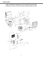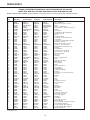
1
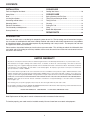
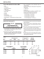
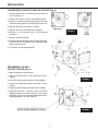
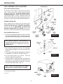
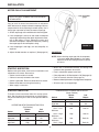
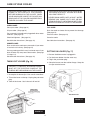
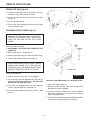
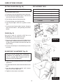
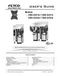
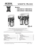
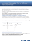
ESSICK
OWNERS
MANUAL
MODEL NO.
ECR 3301
ECR 4000
ECR 4500
ECR 5200
ECR 6600
ECR 7200
CAUTION:
Read All Instructions
Carefully Before Starting
The Installation.
CONVERTIBLE
DOWN/FRONT OUTLET
EVAPORATIVE AIR COOLER
ESSICK AIR PRODUCTS
LITTLE ROCK, ARKANSAS 72209
50209-3
CONTENTS
INSTALLATION
COOLER USE
Tools and Supplies You Need ......................................... 3
Safety Rules ................................................................... 3
Data ................................................................................ 3
Locating Your Cooler ...................................................... 4
Converting to Side Outlet ............................................... 5
Mounting Cooler ............................................................. 6
Electrical Connections ................................................... 7
Final Assembly and Adjustment ..................................... 8
Startup Check List .......................................................... 9
Cooling Your Home ....................................................... 10
COOLER CARE
Spring, Summer and Fall Care ..................................... 11
Taking Off and Putting on Grilles ................................. 11
Taking Off Pad .............................................................. 12
Cleaning ....................................................................... 12
Putting On Pad ............................................................. 13
Oiling ............................................................................ 13
Blower Belt Adjustment ................................................ 13
REPAIR PARTS ...................................................... 38
INTRODUCTION
Your new air cooler uses a new design for evaporating water to cool air. The low energy use of conventional evaporative air coolers is combined with new water handling methods and materials which help overcome most rust problems
of conventional coolers. Your new cooler requires no pad prewetting and is easy to clean. The compact size and modern appearance allow easy installation.
Please read our instructions before you install and use your new cooler. This will help you obtain the full benefits from
your cooler and will also help you avoid any needless service costs that result from causes we cannot control and cannot cover in our warranty.
LIMITED WARRANTY
All products covered by this Instruction Sheet are warranted against defects in workmanship and materials for one year from date of sale.
This warranty does not apply to damage from accident, misuse, or alteration; nor where the connected voltage is more than 5% above the
nameplate voltage; nor to equipment improperly installed or wired or maintained in violation of this Instruction Sheet. This warranty is valid only
in the fifty states of the United States. No other written or oral warranty applies. No employee, agent, dealer or other person is authorized to
give any warranties on behalf of ESSICK.
The customer shall be responsible for all costs incurred in the removal or reinstallation of the product for repairs. Within the limitations of this
warranty, inoperative parts should be returned freight prepaid to ESSICK service center and we will repair or replace, at our option, at no
charge to you with return freight paid by ESSICK. It is agreed that such repair or replacement is the exclusive remedy available from ESSICK AIR
PRODUCTS and that ESSICK IS NOT RESPONSIBLE FOR DAMAGES OF ANY KIND, INCLUDING INCIDENTAL AND CONSEQUENTIAL
DAMAGE. Some states do not allow the exclusion or limitation of incidental or consequential damages, so the above exclusion or limitation
may not apply to you.
This warranty gives you specific legal rights, and you may also have other rights which vary from state to state.
No merchandise should be returned to ESSICK AIR PRODUCTS without return authorization. When requesting a return authorization include
model numbers, part numbers, date and place of purchase.
ESSICK AIR PRODUCTS
5800 MURRAY
LITTLE ROCK, ARKANSAS 72209
Note: Replacement of filter pads is normal maintenance and is not covered in the warranty.
To function properly, your cooler must be installed correctly. You must know how to use tools and equipment.
2
INSTALLATION
TOOLS AND SUPPLIES YOU WILL NEED
•
•
•
•
•
•
•
•
•
•
•
•
• Duct. As Required (a local sheetmetal shop can
supply ducting.)
• Equipment Suitable for installing Duct Through House
Wall or Roof
• 1/4" Water Line
• Saddle Valve
• ECR-7 Wall Switch (7 position). Use ECR-5 (5 position) with existing pump type cooler wiring
• Roof Stand Kit (if cooler is roof mounted)
Pliers
Screwdrivers
Adjustable Wrenches
Tubing Cutter
5
/32 Hex Key Wrench
Electric Drill
Drill Bits
Hammer
Duct Caulking
#10 Sheet Metal Screws
Wiring Supplies, as Required by Local Electrical Code
Level
Cooler ECR 3301 - use ECK-30 kit
Cooler ECR 4000 - use ECK-40 kit
Cooler ECR 4500 - use ECK-40 kit
Cooler ECR 5200 - use ECK-50 kit
Cooler ECR 6600/7200 - use ECK-60 kit
RULES FOR YOUR SAFETY
4. If you mount the cooler on your home roof remember
these safety tips:
1.
WARNING
5. Never install or service a cooler during a storm or
high wind conditions. You could be injured or lose or
damage parts.
TO AVOID FIRE, SHOCK, OR
SERIOUS PERSONAL INJURY
FOLLOWING THESE INSTRUCTIONS.
6. Never wear shoes with slick soles when you work on
a roof. You may slip when you least expect it.
2. The installation must conform to local codes and
utility standards. Use the National Electric Code if
a local code does not exist.
7. Never drain water onto a roof. Water residue may
cause you to slip or may stain your roof. Use a drain
hose to run the drain water to a rain gutter or to a
drain.
3. Disconnect the electric power EVERY TIME you
work on your cooler. When your hands are inside
the cooler you risk injury if the cooler is accidentally
turned on from inside the home.
8. To avoid injury never use the cooler without connecting it to a house duct system or without a sturdy fine
mesh guard over the outlet.
DATA
Cabinet Dimensions
(inches)
Height
Width
Depth
Model
No.
ECR
ECR
ECR
ECR
ECR
ECR
3301
4000
4500
5200
6600
7200
Model
No.
ECR
ECR
ECR
ECR
ECR
ECR
251/4
293/4
293/4
333/4
363/4
363/4
251/4
293/4
293/4
333/4
363/4
363/4
ESSICK EVAPORATIVE
PAD USAGE
Essick
Pad Number
3301
4000
4500
5200
6600
7200
EP-30
EP-40
EP-40
EP-50
EP-60
EP-60
Air Output Opening
(inches)
Height
Width
391/8
353/16
353/16
371/2
4213/16
4213/16
133/4
173/4
173/4
193/4
193/4
193/4
133/4
173/4
173/4
193/4
193/4
193/4
OUTPUT RATINGS
(Cubic Feet per Minute)
Industry Sizing
Rating
3300
4000
4500
5200
6600
7200
3
cfm
cfm
cfm
cfm
cfm
cfm
Operating
Lbs. Weight
(with water)
140
190
195
235
285
290
INSTALLATION
LOCATING YOUR COOLER
The cooler installation must comply with local codes. If
you are not fully qualified to install a cooler, get professional help.
Figure 1 shows some locations for your cooler. Be sure
the intake louvers are clear of obstructions and are
accessible for removal. Do not locate the cooler near vent
pipes, chimneys, or exhausts where odors or fumes
may be drawn into the house. The two drain holes on the
cooler bottom must be clear to allow overflow or drain
access.
This new design Essick cooler may be installed as a bottom or side air outlet cooler. The cooler must be securely
fastened to a frame or pad mount. A roof kit is available
from Essick.
A duct must be attached to the cooler outlet. The duct
must be the same size as the cooler outlet. Sudden duct
size changes will decrease the output of your cooler.
FIGURE 1
WIRING BOX
The wiring box is inside the cooler cabinet. The electrical
supply must be connected to the cooler power leads
inside the box after the cooler is installed. The wiring box
is factory installed for coolers used in the down air outlet
position.
IF YOU INSTALL THE COOLER IN THE SIDE AIR
OUTLET POSITION THE WIRING BOX MUST BE
MOVED. SEE PAGE 5.
FIGURE 2
4
INSTALLATION
CONVERTING COOLER TO SIDE AIR OUTLET (Fig. 4)
1. Remove both louvers and set them where they will
not fall. See pg. 11.
2. Remove four louver clips on side opposite motor.
3. Remove a reservoir by pushing the water crossover
tube from the grommet and lifting out the reservoir.
4. Remove the second reservoir as above.
5. Remove the screw that holds the wiring box.
FIGURE 3
6. Remove 1/8 inch diameter and 7/8 inch diameter
knockouts.
7. Remove two plastic plugs.
8. Loosen screw holding pad motor receptacle bracket,
slide bracket up and detach from cabinet flange.
Repeat on other side.
9. Turn cooler to side outlet position.
REASSEMBLY AS SIDE
OUTLET COOLER (Fig. 5)
1. Move wiring box to new location.
2. Secure wiring box with screw removed at disassembly.
FIGURE 4
3. Install four louver clips removed at disassembly.
4. Install two receptacle brackets removed at disassembly.
5. Install two plastic plugs removed at disassembly.
6. Assemble reservoirs, crossover tube and louvers
after the cooler is installed in location. Use soap or
detergent to lubricate crossover tube before inserting into grommet. DO NOT USE OIL.
FIGURE 5
5
INSTALLATION
LIFTING COOLER
CAUTION: DO NOT LIFT ON THE LOUVERS.
REMOVE THE LOUVERS BEFORE LIFTING.
DO NOT LIFT ON THE CENTER OF THE
CABINET FLANGES.
Lift at cabinet corners.
The cooler may be lifted
by putting a bar or strap
through the panel hole
and lifting by means of
the bar or strap.
FIGURE 6
MOUNTING COOLER
NOTE: THE BOTTOM EDGE NEAREST THE
OUTLET MUST FACE UP THE ROOF.
1. Prepare duct to fit model used. See outlet size specifications on page 3.
2. Cut opening in roof or wall and box in opening.
6. Mount cooler on stand or pad. Cooler must be level
front to back and left to right. Roof stand kits are
available.
3. Install duct and secure to boxed-in opening frame.
Allow two inches to fit into cooler outlet. Allow duct
length for cooler bottom to be 4 inches above roof
at closest point. See figure 7.
7. Be sure to securely fasten four corners of cooler to
stand or pad.
4. Install flashing on roof or wall to prevent water
entry.
8. Caulk duct to the cooler. Caulk the flashing.
5. Measure cooler and lay out mount location.
FIGURE 7
6
INSTALLATION
ELECTRICAL CONNECTIONS
WARNING: TO REDUCE THE RISK OF FIRE OR ELECTRIC SHOCK, DO NOT USE THIS FAN WITH ANY SOLID
STATE SPEED CONTROL DEVICE.
The wiring must comply with local codes. If you are not familiar
with the codes or wiring practices, get professional help.
Use only an Essick ECR-5 or ECR-7 wall mounted switch. This
new cooler does not require prewetting the pads before starting
cooling and does not have a pump. Existing switches with
“pump only” position are not usable.
CAUTION: SHUT OFF THE ELECTRIC POWER AT THE
FUSE BOX BEFORE BEGINNING THE WIRING.
NEW INSTALLATIONS
Use the Essick ECR-7 switch which has four
cooling positions and two vent positions:
Maximum Cool - high and low
Minimum Cool - high and low
Vent - high and low
This switch requires six wires to the cooler (including cooler grounding conductor).
FIGURE 8
COOLER CHANGEOUT
INSTALLATIONS
The Essick ECR-5 switch is suitable for existing
installations where five wires go to the cooler (including cooler grounding conductor). There are
two cool positions and two vent positions.
FIGURE 9
FLOAT VALVE INSTALLATION
INSTRUCTIONS
2. The Water Spout and Water Spout Cover are provided
to prevent water from “spurting” and splashing outside
of the reservoirs. Snap in the Splash Guard Cover as
illustrated below.
It is of the Utmost Importance that the Float Valve, Splash Guard
and Splash Guard Cover be installed exactly as described in
the illustration below.
1. The Float Valve - Must be installed with the narrow side
of the float in the vertical position. If not installed this
way the float will hang up and cause the reservoir drain
pipes to overflow.
7
INSTALLATION
FINAL ASSEMBLY AND ADJUSTMENT
PUT FLOAT VALVE IN COOLER
Put the float valve through the spout hole and cabinet
hole. Tighten the ring nut. Be sure the float moves
straight up and down. TURN THE FLOAT UNTIL A
NARROW SIDE IS UP. Snap the Splash Guard Cover
into the Water Spout as shown. The Water Spout and
Splash Guard Cover are provided to prevent water from
“spurting” and splashing outside the Water Reservoir.
CONNECT WATER LINE
Use a saddle valve to connect 1/4 inch water line to
house cold water pipe or use an outdoor faucet adapter.
Put the line into the valve. Tighten the compression
nut over the ferrule. RUN WATER TO CLEAR LINE
BEFORE CONNECTING TO COOLER. Put line into
float valve. Tighten the compression nut over the ferrule.
PUT IN WATER TRAYS (Fig. 11)
1. Push the drain fitting through the washer and water
tray hole. Tighten the ring nut. Screw the overflow
pipe into the drain fitting. Repeat for the second tray.
FIGURE 10
NOTE: INSTALL DRAIN FITTING INVERTED IF
COOLER IS MOUNTED ON A PAD. CUT OFF THE
OVERFLOW PIPE TOP FLUSH WITH THE HEXAGONAL RING.
2. Put in the float valve side tray first. The crossover
tube & grommet MUST be on the float valve side.
(Fig. 12)
3. Push the crossover tube into the grommet. Use soap
or detergent as a lubricant. DO NOT USE OIL.
FIGURE 11
4. Put the second water tray in place. Push the
crossover tube into the grommet.
5. Turn on the water. Check the water level when the
valve shuts off. If the water level is above the tray
water level mark bend the float rod down. If the level
is too low, bend the rod up. (Fig. 11)
NOTE: CHECK THE CROSSOVER PIPE GROMMETS AND ALL CONNECTIONS FOR LEAKS.
PUT LOUVERS ON COOLER
See page 11.
FIGURE 12
8
INSTALLATION
MOTOR PULLEY ADJUSTMENT
NOTE: ALL DUCT CONNECTED COOLERS MUST
BE ADJUSTED.
Long or small air ducts have excessive air resistance
which decreases air output and motor amperage. You may
compensate for this by adjusting the motor pulley. Use a
clamp type ampmeter to check the motor amperage.
1. Check amperage at the white lead in the wiring box.
2. If the amperage is less than the motor nameplate
amperage, loosen the pulley pitch adjustment screw,
turn in the pulley 1/2 turn, tighten the screw and
recheck the amperes. Repeat as necessary to bring
the amperage to the nameplate rating.
FIGURE 13
3. If the amperage is too high, turn out the pulley as
required.
4. Adjust the belt tension as required. (See page 13)
IMPORTANT
NOTE: When checking amperage with the ampmeter,
all louvers must be in place in the cooler,
otherwise incorrect setting of the drive pulley
will occur.
STARTUP INSPECTION
• Water line is connected securely and fittings and
crossover tube grommets do not leak.
• Float is adjusted for proper water level.
• Pulley alignment is OK. Belt tension is OK (See page 13).
• Pads are correctly installed (See page 13).
• Blower and both pad motors are plugged into receptacles.
• All louver clips are snapped tight.
Before starting the cooler, make sure all installations and
adjustments are correct. Be sure that:
• Cooler is level and duct is sealed.
• Cabinet is securely fastened to the mount.
• Cooler is grounded. Electrical connections are secure.
• Blower wheel does not rub against housing.
• Water supply is turned on.
STARTUP CHECK LIST
OPERATION WITH ESSICK SWITCH ECR-7
(Seven Position)
Blower
Pad
Switch
Motor
Motors
Off
Off
Off
Low Vent
Low
Off
High Vent
High
Off
Minimum
Cool — Low
Low
One On
Minimum
Cool — High
High
One On
Maximum
Cool — Low
Low
Both On
Maximum
Cool — High
High
Both On
To check out the installation follow this startup procedure. Set the control to each position and check operation per the following chart. Be sure to open windows or
vents.
OPERATION WITH ESSICK SWITCH ECR-5
(Five Position)
Blower
Pad
Switch
Motor
Motors
Off
Off
Off
Low Vent
Low
Off
High Vent
High
Off
Low Cool
Low
On
High Cool
High
On
9
HOW TO USE YOUR COOLER
HOW YOUR COOLER WORKS
Your cooler evaporates water to cool air. Evaporative
air cooling is the same natural cooling that happens
when a breeze springs up after a summer shower. You
feel cool because the rain water evaporates and carries
away heat.
Your new cooler has a motor (1) driven blower (2) which
draws outside air through pads (3) which are turned by
drive motors (4). The pads turn through water in trays (5)
filled by the water float valve (6) and water crossover
pipe (7). Air passes through the pads, is cooled by water
evaporation, and is sent into your home.
If the output air is too cool you may switch this cooler
from “Maximum Cool” to “Minimum Cool” (when used
with ESSICK ECR-7 7-position wall switch). Then only
one pad will turn, reducing the cooling effect. You may
also run the cooler in “Vent” when you want fresh air and
no cooling.
FIGURE 14
COOLING YOUR HOME
Your cooler and windows or vents are the two parts of
your air cooling system. Outside air is filtered and
cooled, goes through your home, and carries away heat
and household odors. You control the air cooling flow to
your rooms by opening doors, windows, or vents.
You must have window, door, or vent openings to let
air out when the cooler runs. The total opening
areas you need are shown below:
MODEL
TOTAL OPENING
AREA
ECR 3301
5 Square feet minimum
ECR 4000
8 Square feet minimum
ECR 4500
9 Square feet minimum
ECR 5200
10 Square feet minimum
ECR 6600
12 Square feet minimum
ECR 7200
14 Square feet minimum
FIGURE 15
10
CARE OF YOUR COOLER
CAUTION: ALWAYS SHUT OFF THE ELECTRIC
POWER TO THE COOLER AT THE FUSEBOX
BEFORE WORKING ON THE COOLER. WHEN
YOUR HANDS ARE INSIDE THE COOLER YOU
RISK INJURY IF THE COOLER IS ACCIDENTALLY
TURNED ON INSIDE THE HOUSE.
NEVER WEAR SHOES WITH SLICK SOLES WHEN
YOU WORK ON A ROOF. YOU MAY SLIP WHEN
YOU LEAST EXPECT IT.
NEVER DRAIN WATER ONTO A ROOF. WATER
RESIDUE MAY CAUSE YOU TO SLIP OR MAY
STAIN YOUR ROOF. USE A DRAIN HOSE TO RUN
WATER TO A RAIN GUTTER OR TO THE GROUND.
SPRING CARE:
Clean your cooler. (See page 12)
FALL CARE:
Oil your cooler. (See page 13)
Drain the cooler and water line to prevent frost damage.
(See page 12)
Put a new pad in if the old pad is plugged with dirt or water
hardness. (See page 13)
Clean the cooler. (See page 12)
Check belt tightness. (See page 13)
Cover the cooler.
See lubrication instructions. (See page 13)
See lubrication instructions. (See page 13)
SUMMER CARE:
Drain and clean the cooler every two months if your water
is hard or the air is dusty. (See page 12)
You may prolong pad life in many hard water areas if you
drain the water tray every two to three weeks. (See page
12, steps 1-4).
PUTTING ON LOUVER (Fig. 17)
See lubrication instructions. (See page 13)
2. Put the louver bottom into the water tray.
1. Be sure the blower motor is plugged in.
3. Plug in the pad motor plug.
TAKING OFF LOUVER (Fig. 16)
4. Close the louver over the cabinet flange. Snap the
six clips onto the louver.
CAUTION: TO PREVENT ACCIDENTAL INJURY,
SHUT OFF THE ELECTRIC POWER AT THE
FUSEBOX BEFORE WORKING ON THE COOLER.
1. Unsnap the six louver clips. Use a small screwdriver.
2. Tilt out the louver at the top. Unplug the pad motor
plug.
3. Take off the louver. Set it where it will not fall.
FIGURE 17
FIGURE 16
11
CARE OF YOUR COOLER
TAKING OFF PAD (Fig. 18)
1. Lift up the small roller ends to unsnap the two center rollers. Pull out the two small rollers.
2. Pull out and turn the top roller bearing arm to line
up the slot.
3. Pull out the top roll end.
4. Take out the pad and bottom roller which will slide
out of the bottom slots.
CLEANING YOUR COOLER (Fig. 19)
FIGURE 18
WARNING: NEVER WASH YOUR COOLER INTERIOR WITH A GARDEN HOSE. WATER MAY
HARM THE MOTORS OR GET INTO YOUR
HOUSE.
Clean your cooler as follows:
1. DISCONNECT THE ELECTRIC POWER AT THE
FUSE BOX.
2. Remove the louvers. (See page 11)
3. Connect a garden hose to a water tray drain fitting.
4. Turn out the overflow pipe to drain the tray.
NEVER DRAIN WATER ONTO A ROOF. WATER
RESIDUE MAY CAUSE YOU TO SLIP OR MAY
STAIN YOUR ROOF. USE A DRAIN HOSE TO RUN
WATER TO A RAIN GUTTER OR TO A DRAIN.
5. Drain the other tray.
FIGURE 19
6. Take off the pads if they are dirty or plugged.
7. Use a sponge and mild detergent to wash the dirt
and scale from the trays and louvers. DO NOT GET
WATER ON THE PAD MOTORS.
Operation of Roto Belt Coolers in “Hardwater” Areas.
1. Clean the cooler frequently.
8. If the pads are plugged with hard water deposits
and dirt, replace the pads. See page 13.
2. Remove mineral buildup from water troughs and
Roto Belt to prevent clogging.
9. Put the overflow pipes and grilles in place. (See
page 11)
3. A water analysis will determine: mineral content,
what water treatments can be used, what cleaning
agents should be used.
4. A “bleed-off” kit (Stock No. 8C190) should be installed
to help keep mineral buildup to a minimum.
12
CARE OF YOUR COOLER
PUTTING ON NEW PAD (Fig. 20)
REPLACEMENT PADS
THE PADS NEED NO PREWETTING.
MODEL NUMBER
PAD NUMBER
1. Put the lower roller in pad.
ECR 3301
EP-30
2. Fit the lower roller into the bottom slots in the frame.
ECR 4000
EP-40
3. Push the top roller through the pad. Fit the roll end
over the pad motor shaft drive block.
ECR 4500
EP-40
ECR 5200
EP-50
ECR 6600
EP-60
4. Push the top roller end into the bearing.
5. Turn the bearing arm to hold the roller.
6. Tuck the pad edges under the 2 guides on each
side.
7. Put the two small center rollers in place. Snap the
ends into the holders. (See greasing instructions
below).
OILING (Fig. 21)
Use electric motor oil available or SAE 20 or 30
nondetergent oil. Oil your cooler once a year.
1. Fill the two blower shaft bearing cups.
FIGURE 20
2. Put two or three drops in the two oil fill tubes on the
blower motor. Some motors do not need oil. If motor does not have oil tubes, then the motor does not
require oiling.
3. Put two or three drops in the end bearing on each
pad motor.
BLOWER BELT ADJUSTMENT (Fig. 22)
CAUTION: DO NOT ADJUST BELT TENSION BY
CHANGING THE DIAMETER OF THE MOTOR
PULLEY. ADJUST BELT TENSION ONLY BY
MOVING THE MOTOR BRACKET.
FIGURE 21
1. If you can easily move the belt over 1 inch, it needs
adjustment.
2. To adjust belt tension, loosen the three motor mount
bolts.
3. Push the motor to tighten the belt, until it moves
about 1/2 inch with finger force.
4. Tighten the three motor mount bolts.
FIGURE 22
13
REPAIR PARTS
ESSICK CONVERTIBLE DOWN/FRONT OUTLET EVAPORATIVE AIR COOLER
MODEL NOS. ECR 3301, ECR 4000, ECR 4500, ECR 5200, ECR 6600, ECR 7200
14
REPAIR PARTS
ESSICK CONVERTIBLE DOWN/FRONT OUTLET EVAPORATIVE AIR COOLER
MODEL NOS. ECR 3301, ECR 4000, ECR 4500, ECR 5200, ECR 6600, ECR 7200
NOTICE: Order by PART NUMBER, not by Key Number. Refer to the back cover of this manual for parts ordering information.
KEY
NO.
1
2
3
4
5
6
7
8
9
10
11
12
13
13A
14
15
16
17
18
19
20
23
24
25
26
27
28
29
30
31
32
33
34
35
36
37
38
39
40
41
42
43
44
45
47
48
49
50
51
52
53
54
55
56
57
58
59
*
60
*
*
*
61
ECR 3301
30439
50255
05466-04
581189
30315
586026
582004
30306
05507
05480
30105
30311-00
50294
30550
30347
30433
30551
30549/08133
30287
14864
501244
30347
586026
31086
32013-10
31984
583009
30241
502389
30418-01
30318
30208
30205
30202
27835
14982
29816
30585
32013-20
30552
29996
31985-01
501280
30433
30440
29931-01
31047
30296-01
30248
30234
30236
EP-30
30465
30297-01
30336
29862
586023
50209-3
30339
ECK-30
ECR-5
ECR-7
523122
PART NUMBER
ECR 4000/4500
ECR 5200
30439
30439
50255
50255
05466-04
05466-04
581188/50310
50310
30315
30315
586026
586026
582010/582030
31720
30305-00
30304-00
05507
05507
05480
05480
30105
30105
30311-00
30311-00
50294
50294
30550
30550
30347
30347
30433
30433
30551
30551
30549/08133
30549/08133
30289
30288
14864
14864
501241
501241
30347
30347
586026
586026
31086
31086
32019-10
302025-10
31984
31984
30314/583013
30314
30238-02
30238-01
502389
502389
30418-01
30418-01
30322
30323
30177
30148
30205
30205
30202
30202
27835
27835
14982
14982
29816
29816
30585
30585
32019-20
32025-20
30552
30552
29996
29996
31985-03
31985-02
501243
501243
50485
50489
30878
30440
30214-01
30254-01
31047
31047
30206-01
30250-01
30224-01
30244-01
30211
30235
30212
30237
EP-40
EP-50
30465
30465
30233-01
30256-01
30336
30336
29862
29862
586023
586023
50209-3
50209-3
30338
30337
ECK-40
ECK-50
ECR-5
ECR-5
ECR-7
ECR-7
523122
523122
ECR 6600/7200
30439
50255
05466-04
30491/581191
30315/583054
586026
582088
30304-00
05507
05480
30105
30311-00
50294
30550
30347
30432
30551
30549/08133
30288
14864
501241
30347
586026
31086
32031-10
31984
30314
30238-01
502389
30418-01
30323
30167
30205
30202
27835
14982
29816
30585
32031-20
30552
29996
31985-02
501243
50487
30441
29738-01
31047
29817-01
29861-01
30127
30119
EP-60
30465
29815-01
30336/00061
29862
586023
50209-3
30332
ECK-60
ECR-5
ECR-7
523122
*Unillustrated items
15
PART NAME
Motor Plug
Motor Tail Mount
Machine Screw 5/16 - 18 x 3/4
Motor
Pulley - includes Key 6
Set Screw 5/16 - 18 x .25 Hex. Socket
V-Belt
Motor Mount
Lock Washer 5/16 Helical Spring
Hex Nub 5/16 - 18
Clip
Receptacle Mount
Lock Washer - 5/16 internal tooth
Lock Washer
Screw #8 - 18 x 3/8 Phillips, Type AB
Pad Motor Connector
Machine Screw 5/16 - 18 x 3/8
Screw 1/4 - 14 x 3/8 Type B
Bearing Mount (includes #21, 22)
Bushing
Thrust Washer
Screw #8 - 18 x 1/2, Type B
Set Screw 5/16 - 18 Socket
Overflow Drain Kit
Reservoir
Grommet
Pulley - includes Key 24
Shaft
Float Valve Assembly
Water Shield
Blower Wheel
Baffle
Junction Box Cover
Junction Box
Cupped Washer
Lock Washer #8 Star
Bushing
Screw #8 - 32 x 7/16, Type T, Green
Reservoir
Bushing
Plug
Tube
Collar
Pad Motor Connector
Motor Connector
Louver
Bearing
Side Support
Top Roller
Roller
Bottom Roller
Evaporator Pad (2 Req.)
Screw #10 - 16 x 7/8
Motor Side Support
Pad Motor
Roller Drive
Screw #10 - 32 x 3/8
Owners Manual
Louver Assembly includes Keys 48-59
Roof Stand Kit - Optional
5 Position Switch (Not Supplied)
7 Position Switch (Not Supplied)
Splash Guard Cover
ESSICK
owners
manual
MODEL NO.
ECR
ECR
ECR
ECR
ECR
ECR
3301
4000
4500
5200
6600
7200
HOW TO ORDER
REPAIR PARTS
CONVERTIBLE
DOWN/FRONT OUTLET
EVAPORATIVE AIR COOLER
The model number of your cooler will be found on a label fastened
to the housing.
WHEN ORDERING REPAIR PARTS, ALWAYS GIVE THE FOLLOWING
INFORMATION:
• PART NUMBER
• PART DESCRIPTION
• MODEL NUMBER
• NAME OF ITEM
HOW TO ORDER REPAIR PARTS
All parts listed herein may be ordered through our service center by writing:
ESSICK AIR PRODUCTS
5800 MURRY • LITTLE ROCK, ARKANSAS 72209
501-562-1094