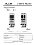
1
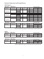
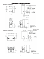
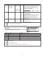
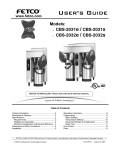
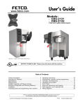
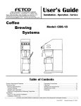
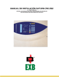
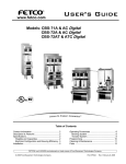
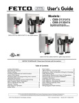
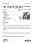
User’s Guide www.fetco.com Models: CBS-2031e / CBS-2031s CBS-2032e / CBS-2032s f f NOTICE TO INSTALLER: Please leave this book with the machine. Table of Contents Contact Information ........................................................2 Description & Features ...................................................2 Specifications..................................................................2 Requirements..............................................................2 Weights and Capacities ..............................................2 Electrical Configuration and Brewing Efficiency .........3 Dimensions & Utility Connections...................................4 Installation.......................................................................5 Operating Instructions ....................................................8 Programming ..................................................................9 Batch Settings .............................................................9 Temperature Settings ...............................................10 Advanced Settings and Diagnostics .........................10 Relay Test .................................................................11 Error Codes ..................................................................12 Service and Support .....................................................13 Cleaning & Maintenance ..............................................13 Parts .............................................................................14 FETCO®, LUXUS®, EXTRACTOR® and Driven To Pioneer Innovation™ are trademarks or trade names of Food Equipment Technologies Company. © 2009 Food Equipment Technologies Company Part # P019 REV. 000 Contact Information Phone: (800) 338-2699 (US & Canada) (847) 719-3000 Fax: (847) 719-3001 FETCO® Food Equipment Technologies Company 600 Rose Road Lake Zurich x IL x 60047-0429 x USA Email: [email protected] [email protected] Internet: www.fetco.com Description & Features The CBS-2030e and CBS-2030s series feature patented intermittent spray over technology, which works like this: The following variables are programmed for each batch size: Brew volume Prewet percent (Percentage of the brew volume) Brew time Prewet delay (The time between prewetting and the brew cycle.) Drip delay (The time between the end of the brew cycle and the unlocking of the brew basket.) Bypass percent (CBS-2031s & 2032s only) (Percentage of the brew volume) Using these variables, the software calculates how much water to use for prewetting and brewing. The total brew time is divided into several 30 second cycles. Within these cycles, the software calculates how long to spray water over the coffee grounds, and how long to pause before the next cycle begins. Features All Models: Two fully programmable batch sizes per side Adjustable prewetting cycle Electronically controlled hot water service Brew temperature protection CBS-2031s & CBS-2032s Only: Magnetic brew basket sensor Brew basket safety locks Adjustable bypass Specifications Requirements Water Requirements: CBS-2031e/2031s: 20-75 psig, ¼ gpm CBS-2032e/2032s: 20-75 psig, ½ gpm Electrical: See electrical configuration chart. Coffee Filters: 13” X 5 ” FETCO Product # F002 Weights and Capacities Brewer Model Weight (empty) Water tank Capacity & Weight. Weight (filled) Dispenser Weight, ea. Dispenser Filled, ea.. Total Weight Brewer & Dispensers, Filled CBS-2031e CBS-2031s CBS-2032e CBS-2032s 35 lbs. 3.0 gal. 25 lbs. 60 lbs. 4.4 lbs. 11 lbs. 71 lbs. 53 lbs. 5.4 gal. 45 lbs. 98 lbs. 4.4 lbs. 11 lbs. 120 lbs. 2 Electrical Configuration and Brewing Efficiency US & Canada CBS-2031e / CBS-2031s Electrical Config. Code E31045 Can be connected Voltage (AC) Phase Wires KW Maximum Amp draw 1 X 1.5 KW 2 X 1.5 KW 120 120/208 120/220 120/240 single single 2 + ground 3 + ground 1.6 2.4 2.6 3.1 13.0 11.3 12.0 13.0 4.9 7.3 8.2 9.7 11.0 11.0 11.0 11.0 1 X 1.7 KW 2 X 1.7 KW 120 120/208 120/220 120/240 single single 2 + ground 3 + ground 1.8 2.7 3.0 3.5 14.7 12.8 13.5 14.7 5.5 8.3 9.2 11.0 11.0 11.0 11.0 11.0 1 X 2.3 KW 2 X 2.3 KW 120 120/208 120/220 120/240 single single 2 + ground 3 + ground 2.4 3.6 4.1 4.7 19.7 17.1 18.1 19.7 7.4 11.0 11.0 11.0 11.0 11.0 11.0 11.0 to 120 VAC or 120/208-240 VAC E31035 Can be connected to 120 VAC or 120/208-240 VAC E31015 Can be connected 3.0 liters per batch Heater Configuration to 120 VAC or 120/208-240 VAC CBS-2032e / CBS-2032s Electrical Config. Code E32015 Batches per Hour* (max 11) Cold Water Hot Water 3.0 liters per batch Heater Configuration Voltage (AC) 2 X 3 KW 120/208 120/220 120/240 Phase Wires KW Maximum Amp draw single 3 + ground 4.6 5.1 6.1 22.4 23.7 25.8 Batches per Hour* (max 22) Cold Water Hot Water 14.6 16.3 19.4 22.0 22.0 22.0 * Based on standard factory settings: 4.0 minute brew time; 0% prewet; 200 F water. Export CBS-2031e / CBS-2031s Electrical Config. Code E31025 3.0 liters per batch Heater Configuration Voltage (AC) 1 X 3 KW 220 240 Phase Wires KW Maximum Amp draw single 2 + ground 2.6 3.1 12.0 13.0 CBS-2032e / CBS-2032s Electrical Config. Code E32025 Batches per Hour* (max 11) Cold Water Hot Water 8.2 9.7 11.0 11.0 3.0 liters per batch Heater Configuration Voltage (AC) 2 X 3 KW 220 240 Phase Wires KW Maximum Amp draw single 2 + ground 5.1 6.1 23.7 25.8 Batches per Hour* (max 22) Cold Water Hot Water 16.3 19.4 22.0 22.0 * Based on standard factory settings: 4.0 minute brew time; 0% prewet; 200 F water. 3 Dimensions & Utility Connections CBS-2031e / CBS-2031s DWG 201108-000 CBS-2032e / CBS-2032s DWG 201109-000 4 Installation (For Qualified Service Technicians Only) Keys To A Successful Installation If not installed correctly by qualified personnel, the brewer will not operate properly and damage may result. Damages resulting from improper installation are not covered by the warranty. Here are the key points to consider before installation: Electrical: All FETCO brewers require NEUTRAL. Ground is not an acceptable substitute. Installation without neutral may cause damage to the electronic components. The electrical diagram is located on the inside of the lower cover. The installation must comply with applicable federal, state, and local codes having jurisdiction at your location. Check with your local inspectors to determine what codes will apply. Plumbing: This equipment is to be installed to comply with the applicable federal, state, or local plumbing codes. The water line must be flushed thoroughly prior to connecting it to the brewer to prevent debris from contaminating the machine. Verify that the water line will provide at least ¼ gallon per minute for the CBS-2031, and ½ gallons per minute for the CBS-2032 before connecting it to the brewer. General: Utilize only qualified beverage equipment service technicians for installation. A Service Company Directory may be found on our web site, http://www.fetco.com. Installation Instructions Brewer Setup 1. Review the Dimensions for the unit you are installing. Verify that the brewer will fit in the space intended for it, and that the counter or table will support the total weight of the brewer and dispensers when filled. 2. The brewer’s legs are shipped inside the brew baskets. Warning: Legs are to be adjusted for Remove the brew basket(s) and the coffee dispenser(s). leveling the brewer only. Do not use Place the brewer on its back and screw in the legs. for height adjustment or extend them 3. Place the brewer on the counter or stand. higher than necessary. 4. When the brewer is in position, level it front to back as well as side to side by adjusting the legs. 5. Remove the lower cover to access the water and electrical connections. Knock-outs are provided in the back and base of the brewer body for the connections. Water Connection 1. Water inlet is a 3/8 inch male flare fitting. 2. The brewer can be connected to a cold or hot water line. Cold water is preferred for best coffee flavor, but hot water will allow for faster recovery times. 3. Install a water shut off valve near the brewer to facilitate service. If an in-line water filter is used, it should be installed after the water shut off valve and in a position to facilitate filter replacement. 4. Flush the water supply line and filter before connecting it to the brewer. 5. Verify that the water line will provide at least ¼ gallon per minute for the CBS-2031, and ½ gallon per minute for the CBS-2032, and that the water pressure is between 20 and 75 psig. 5 Electrical Connection – US & Canada 1. Verify that the actual voltage at the electrical service connection is compatible with the specifications on the brewer’s serial number label. Make sure the electrical service includes neutral. 2. The temperature and water tank fill level are pre-set at the factory. There is no need to turn off the heaters during the installation process. The heaters are disabled by the control board until the tank is full of water. The heating process will start automatically when the tank has filled. 3. The CBS-2031 is factory equipped with a 120 V cord and plug. The CBS-2032 has only a terminal block for connecting the incoming power wires. Consult local codes to determine if a cord and plug can be installed, or if the unit must be hard wired. 4. A fused disconnect switch or circuit breaker on the incoming power line must be conveniently located near the brewer, and its location and markings known to the operators. Warning: To prevent 5. The body of the brewer must be grounded to a suitable building ground. electrical shock, this A ground lug is provided in the brewer next to the power terminal block. unit must be properly Use only 10 gauge copper wire for grounding. grounded. 6. Electrical connections must be secured in-place within the unit to meet national and local standards. 7. Finally, connect the incoming power wires to the terminal block as shown in accordance with applicable codes. CBS-2031e / CBS-2031s Can be connected to 120 VAC or 120/208-240 VAC Factory Configuration 120 VAC, 3 wires Optional Field Conversion* 120/208-240 VAC, 4 wires Step 1: Remove the factory provided 120 V cord & plug from the terminal block. GROUND L1 N Step 2: Connect the incoming wires to the terminal block in accordance with applicable codes. L2 GROUND LUG L2 - NOT USED CORD WITH NEMA 5-20P PLUG L1 N 120V GROUND WIRE L2 120V N 208-240V *This procedure must be performed only by a qualified service technician or electrician. Notice: In order for this product to comply with the requirements of the Underwriters Laboratories listing, the following conditions apply: 1.) This unit must be hard wired for 120/208-240 VAC. 2.) Once the unit is converted to 120/208-240 VAC operation, it cannot be converted back to 120 VAC operation. CBS-2032e / CBS-2032s Can be connected only to 120/208-240 VAC GROUND LUG L1 N 120V L2 120V N GROUND WIRE 208-240V 6 Final Setup 1. Turn on the incoming water supply line and inspect both inside and outside of the brewer for leaks in all fittings and tubes 2. Turn on the incoming power. 3. Press the brewer’s main power switch, which is hidden behind the front leg of the brewer. The control panel on/off switch will begin flashing. Press this switch. 4. Within 6 seconds, the hot water tank will begin filling until the water is sensed by the probe at the top of the tank. The display will read “FIL”. The heaters will be disabled by the control board until the tank is full. 5. While the water is heating, the display will read “LO” and the actual water temperature will be displayed. After the water has reached the set temperature, the display will be blank. There is no “ready” light. 6. Review the Operating Instructions. Brew one full batch (water only) on each side to confirm proper fill levels. The brewer is factory set with water only (no coffee) to dispense the correct amount of water. If the actual volume is slightly different from the programmed volume, fine tuning the brewer may be necessary. See #60 – 61 in the Advanced Settings & Diagnostics section. 7. Re-attach the covers after one final inspection for leaks. Look closely in the top of the brewer at the dispense fittings during this inspection. Operator Training Review the operating procedures with whoever will be using the brewer. Pay particular attention to the following areas: 1. Always pre-heat the dispensers before the first use of each day by filling them half way with hot water, and letting them stand for at least 15 minutes. 2. Don't remove the brew basket until it has stopped dripping. 3. Make sure the dispenser is empty before brewing into it. 4. Show how to attach covers, close, and or secure the thermal dispensers for transporting. 5. Show the location and operation of the water shut off valve as well as the circuit breaker for the brewer. 6. Steam from the tank will form condensation in the vent tubes. This condensation will drip into and then out of the brew baskets. 1/4 cup discharging overnight is possible. Place an appropriate container under each brew basket when not in use. 7. We recommend leaving the power to the brewer on overnight. The water tank is well insulated and will use very little electricity to keep the tank hot. Leaving the brewer in the on position will also avoid delays at the beginning of shifts for the brewer to reach operating temperature. 7 Operating Instructions Control Panel Functions Only switches that are active are illuminated. Switches that are inactive or disabled are invisible. X Main Power Switch Controls all power to brewer Indicator lamp at top of panel. Y Control Panel On/Off Switch Affects only control panel. Does not disconnect main power. Flashing = Off Lit = On Invisible = Main Power Off Z Display ”FILL” = Water tank is filling. ”LO XXX” = Unit is heating, not ready to brew. (XXX = actual temperature.) Blank = Ready to brew. Also displays error messages. [ Stop Switches Stops brew cycle Lit = Brew cycle in progress Invisible = Not brewing, or dripping in progress \ Brew Switches Starts brew cycle Must be held in for 1 second Flashing = Brew cycle in progress Lit = Ready to brew Invisible – Not ready to brew, or batch disabled (See Programming Section) ] Hot Water Switch Dispenses hot water Hold in to dispense from faucet Brewing 1. Turn the main power switch and control panel switch on. 2. Prepare a brew basket with the correct size filter and appropriate amount of coffee. 3. Slide the brew basket completely into the rails. 4. Place a clean, empty, preheated dispenser under the brew basket. 5. Select a batch from the available choices, and hold the corresponding BREW button in for 1 second to start the brew cycle. 6. The STOP button will illuminate, and the selected BREW button will flash, indicating that brewing is in progress. All other BREW buttons will extinguish. 7. When the brew cycle is finished, the STOP button will extinguish and the BREW button will continue flashing, indicating that coffee may still be dripping from the bottom of the brew basket. 8. Before removing the brew basket or dispenser, visually verify that dripping has stopped. Notes: Preheat dispenser by filling at least ½ full with water at brewing temperature. Allow it to sit for at least 15 minutes before draining. 8 Programming Display Batch Settings Turn the brewer off by pressing the main power switch. Press the main power switch again to turn the unit on. The last 2 digits of the model number will display briefly, then S t b. Quickly hold the STOP button for 3 seconds. The display will show the software version. Example: Press STOP to continue. Batches are numbered 1 – 2 (single brewers) or 1 – 4 (dual brewers) 32 Stb PrG 0.0 3.2 MAIN POWER SWITCH IS BEHIND FRONT LEG. PARAMETER SETTING BATCH # 1.1 2.49 Example: Left Side – Large Batch – Volume 2.49 Liters. Next, the first batch parameter is displayed – batch 1, brew volume Use the SCROLL UP and SCROLL DOWN buttons to adjust. Press the STOP button to go to the next parameter – brew time. 1.1 2.49 1.2 4.00 Continue this way until all parameters are programmed for batch #1. (See the chart below for an explanation of each parameter.) Next, batch #2 programming begins. Batches 2 and 4 may be disabled by leaving them set to “OFF”. Change to “ON” to enable. Batches 1 and 3 cannot be disabled. 2.0 OFF After all batches are programmed, go to temperature settings. 7 200 (See next page) Important! After programming, you must press the HOT WATER button to save the settings and exit programming mode, or changes will be lost. You may exit programming at any time. Batch Parameters X=Batch Number (1 - 4) Parameter Name Range On/Off X.1 Batch Enabled or Disabled Brew Volume (Liters) 0.94 – 4.72 X.2 X.3 Brew Time (Min:Sec) Bypass Percent 2:00 – 24:00 0.00 – 40.0% 0:30 1% 4:00 minutes 0% X.0 Increment 0.03 or 0.04 Default Setting Comment Batch 1 & 3 = ON Batch 2 & 4 = OFF 2.49 liters Batch 1 & 3 cannot be disabled. To display gallons, see # 59 in Advanced Settings section. (CBS-2031s / 2032s only) X.4 Prewet Percent 0.00 – 15.0% 1% 0% X.5 Prewet Delay (Min:Sec) 0:10 – 5:00 0:10 1:00 minute X.6 Drip Delay (Min:Sec) 0:30 – 6:00 Minutes 0:10 1:00 minute 9 Percentage of total brew volume Percentage of total brew volume The time between prewetting and start of brew cycle. The time between end of brew cycle and when brew switch stops blinking. Temperature Settings Parameter Name Range 7 Water Temp. (qF) 180qF - 208qF 8 Hot Water Service A (auto) / On / Off 9 Brew at Set Temperature 0-1 Name Range Enter Advanced Settings & Diagnostics 0-1 Parameter 10 Default Setting 200qF A (auto) 1 Default Setting 0 Comment Inside tank. Will be slightly lower at spray head. To display in q Celsius, see # 58 in Advanced Settings. A= Faucet will dispense only when not brewing. On=Faucet always enabled. Off=Faucet always disabled. 0=Will brew at any temperature. 1=Will brew only at set temperature. Note: Changes will not take effect until the next brew cycle is completed. Comment 0 = Skip Advanced Settings & Diagnostics. Loop back to start of batch programming cycle. 1 = Enter Advanced Settings & Diagnostics. Press STOP to continue Important! To save your changes, press to exit programming mode and return to operating mode. Advanced Settings and Diagnostics Address Description Range 50 Water Level in Tank 0-1 Default 52 Brew Basket Sensor State (left / right) 0-1 55 Tank Temperature 180qF - 208qF 56 Brewer Model Number 31 - 52 57 Reload Defaults 0-1 0 58 Temperature Scale F or C F 59 Water Volume Scale LTR or GAL LTR Comment Tests if water is touching probe. 0 = Tank is less than full 1 = Tank is full CBS-2031s / CBS-2032s Only To test, slide the brew basket in and out. Display should toggle between 0 and 1. 0 = Brew basket out. 1 = Brew Basket in. Displays current tank temperature. If temperature is below 175qF, displays “LO”. Must be set for the correct model number of the brewer: 31 for CBS-2031e or 2031s, 32 for CBS2032e or 2032s. Changes all settings to default factory settings. 0 = Do not reload defaults 1 = Reload all default settings If 1 is selected, you must advance to the next address for this change to take effect. Does not change address 56 – model number. F = Displays temp in degrees Fahrenheit C = Displays temp in degrees Celsius LTR = Displays volume in liters GAL = Displays volume in gallons 10 Address 60 and 61 Description Left Brew Valve Flow Rate Right Brew Valve Flow Rate Range 0.35 – 2.24 Default Comment 1.30 Use this to compensate for minor discrepancies in actual volume versus programmed volume. Set lower to increase volume, higher to decrease volume. The following formula can be used to determine the correct setting: If #59 is LTR or 0.09 – 0.59 0.39 ACTUAL VOLUME PROGRAMMED VOLUME If #59 is GAL 64 Keypad Test 0-1 0 65 Relay Test 0-1 0 X CURRENT SETTING = NEW SETTING Tests function of control panel switches. 0 - Skip keypad test 1 - Keypad test active Starting at the top, press each button. Display will read the name of the switch being pressed. Brew switches are named S1, S2, S3, etc. The hot water switch must be pressed last, as this will exit the test. 0 - Skip relay test. Loop back to #50 1 – Relay test active. Press STOP to continue Press to save the settings and exit Diagnostic mode. Press again to exit Programming mode and return to Operating mode. Relay Test Tests the individual relays which control various components. Use either batch button to actuate the relays. Warning: During these tests, hot water may be dispensed from the va lve being tested. To begin, you must first press the blinking Control Panel Power Switch. Address 90 91 92 93 94 95 96 Description Left or Single Brew Valve Right Brew Valve Left or Single Bypass Valve Right Bypass Valve Hot Water Faucet Fill Valve Heater Comment CBS-2031s / CBS-2032s Only CBS-2031s / CBS-2032s Only To protect the heaters, this test will work only if the tank is full. Press to exit Relay Test. Press again to exit Diagnostic mode. Press again to exit Programming mode and return to Operating mode. 11 Error Codes Code Description Possible Cause Corrective Action 001 Internal Error System had to reload default settings. Control board failure. 050 Shorted temperature probe. Probe failure. Clear error. Re-program the brewer to the desired specifications. If error occurs again, replace control board. Replace probe. 051 Open temperature probe. 075 or NO BAS CBS-2031e / 2032e Brew Basket Sensor Bad probe connection, or probe failure. These models do not have brew basket sensors or locks. This error indicates a bad connection on the brown jumper wire on the Molex connector connected to the top of the control board. Brew basket sensor or lock has failed. If the brew basket can be pulled out during the brew cycle, the brew basket lock has failed. Magnet in brew basket handle is missing or loose. Water supply flow rate is too low. 075 CBS-2031s / 2032s Brew basket lock or sensor failure. 100 Initial Fill Error Initial fill time was more than 15 minutes. 101 Error on refill Tank did not refill within 3 minutes. Water supply flow rate is too low. 102 Unwanted Fill When brewer is idle, the fill valve was activated for more than 30 seconds during a 1 hour period. Possible leak in tank, fitting, or valve. 200 201 202 255 Flat Line Temperature (Water is boiling) System is calling for heat, but the temperature does not rise at least 2qF within 10 minutes. Heater Open System is calling for heat, but the temperature does not rise at least 2qF within 10 minutes. This error is disabled during brewing and while using the hot water faucet. Heater Short System is not calling for heat, but temperature rises more than 5qF. Keypad Error A switch was pressed for more than 45 seconds. Check all connections. Replace probe if necessary. Press both ends of the jumper wire into the connector to make better contact. Repair or replace brew basket sensor or lock. Remove brew basket handle. Place magnet in correct position. Watch for short potting during brew cycle. Investigate cause of low flow rate. (Clogged water filter, etc.) Watch for short potting during brew cycle. Investigate cause of low flow rate. (Clogged water filter, etc.) Check inside of machine for leaks. How to Clear Error Codes Turn main power switch off and on. Turn main power switch off and on. Turn main power switch off and on. Press the flashing control panel power switch to resume operation. Press the control panel power switch. Error message is cleared automatically at end of brew cycle. Turn main power switch off and on. Output on control board has failed, causing a dispense valve to open. Triac is stuck closed, bad output on control board, or temperature is set too high for altitude. Replace control board. Check triacs, check control board output, or adjust temperature for altitude. Turn main power switch off and on. Heating element failure. Check and replace heating elements if necessary. Turn main power switch off and on. Possible triac stuck closed, or bad output on control board. Check triac and control board. Enter programming mode, then exit programming mode. Switch was held in too long, or switch is stuck closed. Clear error and try again. If error occurs without switch being pressed, replace input board. Turn main power switch off and on. 12 Service and Support For service and support information, contact the Technical Support department. Our hours are 7:00 AM to 6:00 PM Central Time, Monday through Friday. Phone: (800) 338-2699 or (847) 719-3000 Email: [email protected] Utilize only qualified beverage equipment service technicians for service. A Service Company Directory may be found on our web site, http://www.fetco.com. Cleaning & Maintenance Daily: Wipe the area above the brew basket to remove coffee residue. Daily or Weekly: CSD Versions: Clean the Cascading Spray Dome (CSD) with a soft brush and detergent. It may also be cleaned in a dishwasher – top rack only. The CSD is held in place by four magnets. To remove it, grasp the bottom and pull down. CSD Spray Plate Versions: The spray plate should be removed and cleaned to remove hard water deposits. In areas with extremely hard water, it may be necessary to do this daily. Weekly cleaning may be sufficient in some areas. When cleaning the spray plate, make sure that each hole is completely free of mineral deposits. Use a toothpick to clean out each hole. Never use metal objects or abrasives on the spray plate’s Teflon coating. SPRAY PLATE Quarterly: x Check water temperature, adjust if necessary. x Check brew levels, adjust if necessary. x Inspect all fittings and hoses for leaks. x Inspect inside of tank for lime deposits. De-lime tank and probes if necessary. This procedure should be done by a qualified service technician. 13 Parts Figure 1 – CBS-2031e / CBS-2031s Main Assembly 57 57 DWG 101194-C ITEM # QTY 1 2 2 3 4 5 5 6 7 7 8 9 10 11 12 1 1 1 2 4 1 1 4 1 1 1 1 1 4 1 Old part number 29007 15007 51042 29019 24012 31078 03074 82020 31031 PART # 001051 108001 108037 1029.00006.00 1084.00023.00 1051.00011.00 51055 1029.00012.00 57006 57017 1024.00020.00 1031.00004.00 1003.00019.00 1082.00019.00 1031.00005.00 DESCRIPTION WELDMENT CBS-2031e (For Illustration only, not sold as a commercial part) SWITCHING/CONTROL BOARD, 5 KEYS, S2P (CBS-2031e ONLY) SWITCHING/CONTROL BOARD, 5 KEYS, S2P (CBS-2031s ONLY) NUT, #4-40 KNURLED THUMB STANDOFF, MALE-FEMALE, THREADED HEX 4-40-1/2" BOARD, POWER SUPPLY-120VAC BOARD, POWER SUPPLY-220VAC EXPORT ONLY SPACER, .25" HEX X 1" LG, FEM #4-40 THREAD FILL VALVE, S-53 120VAC FILL VALVE, S-53 220VAC GASKET, S-53 FILL VALVE FITTING, S-53 FILL VALVE INLET BRACKET, S-53 INLET VALVE SCREW, S-53 FILL VALVE FITTING, 90° MALE ELBOW, 3/8 TUBE OD X 3/8 MPT 1 EXPORT ONLY EXPORT ONLY 13 14 15 16 17 17 17 18 19 20 21 22 23 24 25 25 25 26 27 28 29 30 31 32 33 34 35 36 37 38 38 39 40 41 42 44 45 46 47 48 49 50 51 52 53 54 55 57 57 1 1 1 2 1 1 1 7 13 1 1 1 4 2 1 1 2 1 1 1 1 1 1 1 1 1 1 1 1 1 1 1 3 1 1 1 1 1 1 5 1 1 1 1 10 1 1(4 ea) 1(4 ea) 86040 65002 86032 102189 52026 58054 83026 84002 002065 33007 102192 102193 57073 83051 41016 46029 102190 44004 86038 86007 1086.00008.00 52050 1065.00002.00 1086.00004.00 1102.00106.00 1052.00007.00 1058.00014.00 1083.00011.00 1084.00006.00 SEE FIG.5A/5B 1112.00093.00 1013.00030.00 73029 29021 1102.00108.00 1102.00130.00 1057.00014.00 1083.00016.00 104028 22062 22063 45077 1041.00004.00 1046.00019.00 102139 1102.00011.00 1044.00003.00 402025 402035 63019 63018 25056 25058 1086.00002.00 86020 25059 25102 25055 25057 25064 1086.00001.00 01506 01507 401217 102191 82053 101171 1082.00017.00 1084.00011.00 CONNECTOR, CABLE CLAMP, 3/4" TRADE SIZE TERMINAL BLOCK CONNECTOR, COPPER LUG BUSHING, SNAP, 1" MOUNTING HOLE DIA ASSEMBLY, POWER BRACKET, CBS-2000e BREAKER, 5A CIRCUIT (Not sold individually, is sold as part of 1102.00106.00–above) SWITCH, PUSH BUTTON (Not sold individually, is sold as part of 1102.00106.00–above) WASHER, #8 SCREW SIZE, INTERNAL TOOTH LOCK NUT, HEX, #8-32 MACHINE SCREW ASSEMBLY, SMALL SPRAY HEAD WELDMENT, HOT WATER FAUCET LOCKNUT, 7/16 STRAIGHT PIPE THREAD LEG, THERMOPLASTIC, 2.50"(63mm) SPACER, #8 SCREW SIZE, ½ OD X ¼ LG, ROUND UNTH. ASSEMBLY, HOT WATER VALVE, 120VAC ASSY. HOT WATER VALVE , 220VAC (ELBOW FITTING VALVE REBUILD KIT, DSV11 WASHER, #8 SCREW SIZE, FLAT ASSEMBLY TANK CBS-2031e (SEE FIG 2) INSULATION TANK FRONT CBS-2031e INSULATION TANK BACK CBS-2031e OVERLAY CBS-2031e LABEL, EXTRACTOR LABEL, POWER SWITCH ASSEMBLY, WATER LEVEL PROBE, CBS-2030 ASSY, DIGITAL TEMP. PROBE, 5.0" LG (ORDER AS K061) LABEL, GROUND HARNESS, LOW AMP, ELECTRICAL, CBS-2031e, TWO HEATERS HARNESS, HIGH AMP, ELEC. 2 HEATER WIRE SET CBS-2031e CORD, 120 VAC, 12/3 AWG ,20 AMP , W/5-20P NEMA PLUG CORD, 120 VAC, 12/3 AWG ,15 AMP , W/5-15P NEMA PLUG TUBE, 3/4"OD X 1/2"ID X 4"LG, BREW TUBE 5/8"OD X 3/8"ID X 2.5"LG, HOT WATER FAUCET CLAMP, HOSE, 0.665-0.783" DIA RANGE CLAMP, HOSE, .875"-.750" DIA RANGE TUBE, 5/16"OD X 3/16"ID X 9 1/4"LG VENT TUBE, 1/4"OD X 1/8"ID X 20" LG VENT HOT WATER VALVE TUBE, 5/8"OD X 3/8"ID X 12"LG DRAIN TUBE, 5/8"OD X 3/8"ID X 14 1/2"LG, COLD WATER TUBE, 5/8"OD X 3/8"ID X 6.5"LG. HOT WATER CLAMP, HOSE, .590"-.673" DIA RANGE COVER TOP CBS-2031 & 41 COVER BASE UPPER CBS-2031 WIRING DIAGRAM, CBS-2031e, L1, L2, N, + GR ASSEMBLY, RIGHT COVER CBS-2030's SCREW, # 6-32 X 1/2" TRUSS HD PH BREW BASKET ASSY., 13 X 5, DIA HOLE 0.218" (SEE FIG. 6) (4) MACHINE SCREW, # 6-32 X 1/2" TRUSS HD PHIL. (4) “J” Nut for Machine Screw, # 6-32 X 1/2" Truss Hd Phil ADDITIONAL PARTS FOR CBS-2031s, NOT SHOWN ON DRAWING 102207 1 1102.00113.00 ASSEMBLY, REED SWITCH 101160 1 1102.00047.00 ASSEMBLY, BREW BASKET LOCK 101174 1 1102.00135.00 brew basket lock assy., 220 VAC. EXPORT 57044 1 1057.00020.00 VALVE, BYPASS LEFT 120 VAC 57077 1 1057.00029.00 VALVE, BY-PASS, LEFT, 220VAC 57073 1057.00014.00 VALVE REBUILD KIT, DSV11 101175 1 B003280B1 ASSEMBLY, BREW BASKET CBS-2040'S 2 EXPORT ONLY EXPORT ONLY EXPORT ONLY Figure 2 – CBS-2031e / CBS-2031s Tank Assembly, PART # 104028 DWG 104028-A ITEM # QTY 1 2 3 4 5 6 7 8 9 9 9 9 10 11 1 1 1 3 3 1 1 1 2 2 2 2 1 1 Old part number 24002 102013 31117 83042 25098 31116 83041 PART # 004042 1024.00007.00 1102.00007.00 1031.00007.00 1083.00006.00 31081 1025.00001.00 31036 107025 107019 107020 107021 1031.00020.00 1083.00014.00 DESCRIPTION WELDMENT TANK CBS-2031e O-RING, TANK COVER ASSEMBLY, TANK COVER LOCKNUT, 1/4 STRAIGHT PIPE THREAD WASHER, .875"OD X .562"ID, FLAT PLUG, HEX HEAD 1/4" MPT FITTING, COMPRESSION TUBE FITTING COMPR. MALE CONNECTOR 1/4 TUBE OD X 1/4 MPT HEATER ASSY., 1500W/120VAC HEATER ASSY., 1700W/120VAC HEATER ASSY., 2300W/120VAC HEATER ASSY., 3000W/240VAC LOCKNUT, 1/8 STRAIGHT PIPE THREAD WASHER, .812"OD X .412"ID, FLAT 3 EXPORT ONLY 12 13 14 15 16 17 18 19 20 21 22 23 24 25 26 27 28 1 2 2 8 8 1 1 1 3 1 1 2 1 1 2 2 1 31005 03332 53071 83011 84001 31118 31021 31128 31027 13072 03297 59008 84007 1031.00032.00 1003.00005.00 1053.00004.00 1083.00009.00 1084.00010.00 1031.00033.00 83044 31071 1031.00029.00 25110 25111 1031.00031.00 1031.00030.00 1013.00045.00 1003.00006.00 1059.00001.00 1084.00022.00 FITTING, 90 DEG. ELBOW, 1/4 HOSE ID X 1/8 MPT BRACKET 2, ONE SHOT THERMOSTAT THERMOSTAT, SINGLE SHOT, 25 AMP WASHER, #6 SCREW SIZE, INTERNAL NUT, HEX, #6-32, UNDERSIZED, ZINC PLATED LOCKNUT, 3/8 STRAIGHT PIPE THREAD WASHER, 1.125"OD X 0.750"ID, FLA FITTING, 1/2 HOSE ID X 3/8" MPT BUSHING, 3/4-16 X 1/4 NPSM, HEX HEAD VALVE, DRAIN (REQUIRES # 25111 TUBE) TUBE, DRAIN VALVE FITTING, 90° ELBOW, 3/8 HOSE ID X 1/4 MPT FITTING, COMPR 90° MALE ELBOW, 3/8 TUBE OD X 1/4 MPT OUTLET, INSIDE TANK HOT WATER SINK, HEAT FOR 40A TRIAC TRIAC 40A, 600V NUT, 3/4-16 HEX JAM (TANK DRAIN, INLET TUBE) 4 Figure 3 – CBS-2032e / CBS-2032s Main Assembly DWG 101196-D Old part number ITEM # 1 QT Y 1 2 1 104027 3 1 22041 4 1 5 2 6 1 102189 22042 SEE FIG.5A/5B 1102.00106.00 6 1 52026 1052.00007.00 BREAKER, 5A CIRCUIT 6 1 58054 1058.00014.00 SWITCH, PUSH BUTTON (Not sold individually, is sold as part of 1102.00106.00–above) 7 2 86032 1086.00004.00 BUSHING, SNAP, 1" MOUNTING HOLE DIA 8 1 9 1 10 1 402023 HARNESS, LOW AMP, ELECTRICAL, CBS-2032e, TWO HEATERS 11 1 402032 HARNESS, HIGH AMP, TWO HEATER WIRE SET CBS-2032e 12 2 13 1 PART # DESCRIPTION 001050 WELDMENT, CBS-2032e (For Illustration only, not sold as a commercial part) 52050 65002 1065.00002.00 29021 102192 1102.00108.00 ASSEMBLY, TANK CBS-2032e (SEE FIG. 4) INSULATION TANK FRONT CBS-2032e INSULATION TANK BACK CBS-2032e ASSEMBLY, SMALL SPRAY HEAD ASSEMBLY, POWER BRACKET, CBS-2000e (Not sold individually, is sold as part of 1102.00106.00–above) TERMINAL BLOCK CONNECTOR, COPPER LUG SPACER, #8 SCREW SIZE HOT WATER VALVE ASSEMBLY, 120VAC 5 13 1 13 102193 1102.00130.00 HOT WATER VALVE ASSEMBLY, 220VAC VALVE REBUILD KIT, DSV11 57073 1057.00014.00 14 2 83051 1083.00016.00 WASHER, #8 SCREW SIZE, FLAT 15 7 83026 1083.00011.00 WASHER, #8 SCREW SIZE, INTERNAL TOOTH LOCK 16 17 84002 1084.00006.00 17 1 17 1 18 4 15007 1084.00023.00 STANDOFF, MALE-FEMALE, THREADED HEX 4-40-1/2" 19 3 29007 1029.00006.00 NUT, #4-40 KNURLED THUMB 20 1 51042 1051.00011.00 BOARD, POWER SUPPLY-120VAC 20 1 51055 BOARD, POWER SUPPLY-220VAC 21 4 29019 1029.00012.00 SPACER, .25" HEX X 1" LG, FEM #4-40 THREAD 22 1 002065 1112.00093.00 WELDMENT, HOT WATER FAUCET 23 1 33007 1013.00030.00 LOCKNUT, 7/16 STRAIGHT PIPE THREAD 24 1 45078 OVERLAY CBS-2032e 25 3 73029 LEG, THERMOPLASTIC, 2.50"(63mm) 26 1 57006 FILL VALVE, S-53 120VAC 26 1 57017 FILL VALVE, S-53 220VAC 27 1 24012 1024.00020.00 GASKET, S-53 FILL VALVE 28 1 31078 1031.00004.00 FITTING, S-53 FILL VALVE INLET 29 1 03074 1003.00019.00 BRACKET, S-53 INLET VALVE 30 4 82020 1082.00019.00 SCREW, S-53 FILL VALVE 31 1 31031 1031.00005.00 FITTING, 90° MALE ELBOW, 3/8 TUBE OD X 3/8 MPT 32 1 86040 1086.00008.00 CONNECTOR, CABLE CLAMP, 3/4" TRADE SIZE 33 1 102190 1000.00061.00 ASSY, DIGITAL TEMP. PROBE, 5.0" LG 34 1 102139 1000.00028.00 35 2 102195 36 2 25056 TUBE, 3/4"OD X 1/2"ID X 4"LG, BREW 37 1 25064 TUBE, 5/8"OD X 3/8"ID X 6.5"LG. HOT WATER 38 1 25055 TUBE, 5/8"OD X 3/8"ID X 12"LG DRAIN 39 1 25057 TUBE, 5/8"OD X 3/8"ID X 14 1/2"LG, COLD WATER 40 1 25058 TUBE 5/8"OD X 3/8"ID X 2.5"LG, HOT WATER FAUCET 41 1 25059 TUBE, 5/16"OD X 3/16"ID X 9 1/4"LG VENT 42 4 43 2 44 5 86007 45 1 25102 25102 46 1 44004 1044.00003.00 LABEL, GROUND 47 2 44024 1044.00004.00 LABEL, WARNING-HIGH VOLTAGE 48 1 01479 49 1 01463 50 1 401219 WIRING DIAGRAM, CBS-2032e, 1PH, 3 WIRE + GR, 2 HEATERS 102191 ASSEMBLY, RIGHT COVER CBS-2030's 86038 NUT, HEX, #8-32 MACHINE SCREW 108002 SWITCHING/CONTROL BOARD, 8 KEYS, D2P (CBS-2032e ONLY) 108038 SWITCHING/CONTROL BOARD, 8 KEYS, D2P (CBS-2032s ONLY) 1086.00002.00 CLAMP, HOSE, 0.665-0.783" DIA RANGE CLAMP, HOSE, .875"-.750" DIA RANGE 1086.00001.00 CLAMP, HOSE, .590"-.673" DIA RANGE TUBE, 1/4"OD X 1/8"ID X 20" LG VENT HOT WATER VALVE COVER, TOP CBS-2032 & 42 COVER, UPPER BASE CBS-2032e 1 52 10 53 1 54 1 46029 1046.00019.00 LABEL, POWER SWITCH 55 1 41016 1041.00004.00 LABEL, EXTRACTOR 57 2 101171 B007218B1 BREW BASKET ASSY. 13" X 5", W/ 0.218" HOLE, 0.19" FLANGE (SEE FIG. 6) B006218B1 BREW BASKET ASSY. 13" X 5", W/ 0.218" HOLE, 0.25" FLANGE (SEE FIG. 6) 46027 EXPORT ONLY ASSEMBLY, WATER LEVEL PROBE, CBS-2030'S 86020 1082.00017.00 EXPORT ONLY ASSEMBLY, BUMPER, 2030e 51 82053 EXPORT ONLY SCREW, # 6-32 X 1/2" TRUSS HD PHIL., MACHINE LABEL, SPRAY HOUSING ADDITIONAL PARTS FOR CBS-2032s, NOT SHOWN ON DRAWING 101160 1102.00047.00 ASSEMBLY, BREW BASKET LOCK 2 2 101174 2 1 102207 57043 1 57076 1 57073 1102.00135.00 1102.00113.00 1002.00109.00 brew basket lock assy., 230 VAC. EXPORT ASSEMBLY, REED SWITCH VALVE, BYPASS RIGHT 120 VAC 1002.00132.00 1002.00134.00 1057.00014.00 VALVE, BY-PASS, RIGHT, 230VAC VALVE, BY-PASS, RIGHT, 200VAC VALVE REBUILD KIT, DSV11 6 EXPORT ONLY EXPORT ONLY JAPAN 6 4 1 83051 84030 57044 1083.00016.00 1084.00015.00 1102.00110.00 WASHER, #8 SCREW SIZE, FLAT LOCKNUT, #8-32 SCREW SIZE, HEX THIN NYLON INSERT VALVE, BYPASS LEFT 120 VAC 1 57077 1102.00131.00 VALVE, BY-PASS, LEFT, 230VAC 1 1 101175 1002.00133.00 B003280B1 VALVE, BY-PASS, RIGHT, 200VAC ASSEMBLY, BREW BASKET CBS-2040'S (SEE FIG. 7) 7 EXPORT ONLY JAPAN Figure 4 – CBS-2032e / CBS-2032s TANK ASSEMBLY Part Number #104027 DWG 104027-A 8 Old part number ITEM # QTY PART # DESCRIPTION 1 2 1 004043 WELDMENT TANK CBS-2032e 2 107021 3 1 31116 1031.00020.00 4 1 83041 1083.00014.00 WASHER, .812"OD X .412"ID, FLAT 5 1 31005 1031.00032.00 FITTING, 90 DEG. ELBOW, 1/4 HOSE ID X 1/8 MPT 6 3 31117 1031.00007.00 LOCKNUT, 1/4 STRAIGHT PIPE THREAD 7 2 31118 8 2 1031.00033.00 83044 LOCKNUT, 3/8 STRAIGHT PIPE THREAD WASHER, 1.125"OD X 0.750"ID, FLA HEATER ASSY., 3000W/240VAC LOCKNUT, 1/8 STRAIGHT PIPE THREAD 9 2 003332 1003.00005.00 BRACKET 2, ONE SHOT THERMOSTAT 10 2 003297 1003.00006.00 SINK, HEAT FOR 40A TRIAC 11 2 59008 1059.00001.00 TRIAC 40A, 600V 12 8 83011 1083.00009.00 WASHER, #6 SCREW SIZE, INTERNAL 13 8 84001 14 2 1084.00010.00 31071 NUT, HEX, #6-32, UNDERSIZED, ZINC PLATED FITTING, 1/2 HOSE ID X 3/8" MPT 15 3 83042 16 1 1083.00006.00 31081 WASHER, .875"OD X .562"ID, FLAT PLUG, HEX HEAD 1/4" MPT 17 1 18 1 25098 1025.00001.00 FITTING, COMPRESSION TUBE 19 1 84007 1084.00022.00 NUT, 3/4-16 HEX JAM (TANK DRAIN, INLET TUBE) 20 3 31021 1031.00029.00 BUSHING, 3/4-16 X 1/4 NPSM, HEX HEAD 21 1 31027 1031.00030.00 FITTING, COMPR 90° MALE ELBOW, 3/8 TUBE OD X 1/4 MPT 22 1 13072 1013.00045.00 OUTLET, INSIDE TANK HOT WATER 23 2 31128 24 1 1031.00031.00 25110 FITTING, 90° ELBOW, 3/8 HOSE ID X 1/4 MPT VALVE, DRAIN (REQUIRES # 25111 TUBE) 25 1 26 1 24002 1024.00007.00 27 1 102013 1102.00007.00 ASSEMBLY, TANK COVER 28 2 53071 1053.00004.00 THERMOSTAT, SINGLE SHOT, 25 AMP 31036 25111 FITTING COMPR. MALE CONNECTOR 1/4 TUBE OD X 1/4 MPT TUBE, DRAIN VALVE O-RING, TANK COVER 9 Figure 5a – CSD VERSIONS: ASSY, CSD SMALL SPRAY HEAD, 120VAC, PART # 102395 ASSY, CSD SMALL SPRAY HEAD, 220VAC, PART # 102396 (EXPORT ONLY) Old part ITEM # QTY number 1 4 2 2 3 4 5 1 NOT SHOWN KIT PART # 1057.00013.00 VALVE, BREW, SMALL, 120VAC 57047 1 1 DESCRIPTION #8 X 3/4'' PAN HD. PHIL. T.S. 82112 18-8 S.S. SCREW 57071 VALVE ASSY., DSV-11, 220 VAC EXPORT ONLY 1057.00014.00 VALVE REBUILD KIT, DSV11 57073 1 102397 ASSY., CSD, SPRAY. HOUSING -SMALL 1 102363 ASSEMBLY, CASCADE SPRAY DOME 1000.00079.00 CSD Retro-Fit Kit. Includes all parts and clear instructions to update 5b (below) Into 5a- the current CSD brewer Figure 5b – SPRAY PLATE VERSIONS: ASSY, SMALL SPRAY HEAD, 120VAC, PART # 102080 ASSY, SMALL SPRAY HEAD, 220VAC, PART # 102158 (EXPORT ONLY) ITEM # Old part QTY number 1 4 2 2 3 4 5 6 1 1 1 1 1 1 NOT SHOWN KIT 10 PART # DESCRIPTION #8 X 3/4'' PAN HD. PHIL. T.S. 18-8 S.S. SCREW 1057.00013.00 VALVE, BREW, SMALL, 120VAC 82112 57047 57071 VALVE ASSY., DSV-11, 220 VAC 57073 1057.00014.00 VALVE REBUILD KIT, DSV11 24054 1024.00029.00 O-RING 4.237 ID, 0.103 IN CS 102082 SPRAY HOUSING ASSY. 102081 102081 SPRAY PLATE ASSY., 4 7/8" DIA. 1000.00079.00 CSD Retro-Fit Kit. Includes all parts and clear instructions to update 5b Into 5a- the current CSD brewer (above) EXPORT ONLY NOTE: The round and square brew baskets pictured below are not interchangeable. Use only the type of brew basket that originally came with the brewer. Figure 6 – Brew Basket Assembly, 13” X 5”, Part # B006218B1 (ROUND) ITEM QTY Old part number PART # DESCRIPTION 1 1 09021 1009.00008.00 BASKET, WIRE, 13" X 5" 2 2 82118 1082.00021.00 SCREW, 8-18 X 3/4" PAN HD PHIL. PLASTICS 3 1 23074 1023.00110.00 HANDLE BREW BASKET 4 1 46011 1046.00007.00 LABEL, BREW BASKET WARNING NOT SHOWN F002 PAPER FILTERS, 13” X 5” 500 PER CASE COLOR BREW BASKET HANDLES Old part number PART # DESCRIPTION HANDLE BREW BASKET RED 23169 1023.00111.00 CBS-18/2030'S 23171 1023.00112.00 HANDLE BREW BASKET GREEN Figure 7 – Brew Basket Assembly, 13” X 5”, Part # B003280B1 (SQUARE) ITEM QTY Old part number 1 1 09022 1009.00006.0 BASKET WIRE CBS-2040'S 0 2 1 23117 1023.00089.0 HANDLE, BREW BASKET (INCLUDES #8 – MAGNET) 0 3 1 46011 1046.00007.0 LABEL, BREW BASKET WARNING 0 5 1 82096 1082.00040.0 SCREW, 1/4-20 X .5, FLT HD, PHILLIPS,18-8 SS, W/ PLASTIC PATCH 0 NOT SHOWN 101171 B003280B1 Brew Basket, 13" X 5", W/0.218" Hole, 0.19" Flange (Usedbefore 9/2007) PART # NOT SHOWN DESCRIPTION F002 PAPER FILTERS, 13” X 5”500 PER CASE COLOR BREW BASKET HANDLES Old part number PART # DESCRIPTION 23106 1023.00087.00 Brew Basket Handle - Green 23107 1023.00088.00 Brew Basket Handle - Orange 23148 1023.00090.00 Brew Basket Handle - Red 11