1
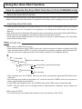
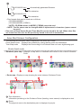
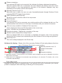
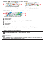
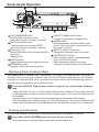
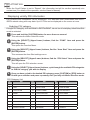
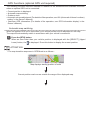
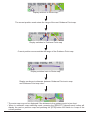
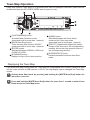
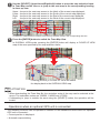
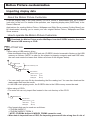
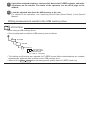
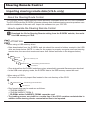
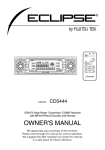
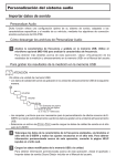
E-iSERV Operation Guide
CD7100
We appreciate your purchase of
this head unit. Please read through
this manual in order to ensure correct operation.
We suggest that after reading it
you keep this manual in a safe
place for future reference.
Using the Area Shot function
How to operate the Area Shot function (U.S.A./CANADA only)
About the Area Shot function
Using the Area Shot function, route data retrieved from the ECLIPSE E-iSERV web site containing
maps to predetermined destinations and guidance information can be displayed on your main unit.
Importing Area Shot data
• Load the Area Shot data in the USB memory or CD-R, which is downloaded from the E-iSERV
(web site), to the unit. For details of the operation, see ‘Reading Area Shot data’ in the Owner’s
Manual.
• After loading all Area Shot data following the above instructions, press and hold the [MUTE/Area
Shot] button for more than one second to activate the Area Shot function.
• Press and hold the [MODE] button for more than one second to switch between the Town Map
and the Route Assist view.
ATTENTION
<When using a USB memory drive>
• Data downloaded from the E-iSERV (web site) should be saved to folders created in the USB
drive as shown below (NOTE: in order for the system to properly recognize and load Area Shot
data, the user must create and name their folders as shown in the diagram below).
ECLIPSE
Must be created by user
AREA
XXXXXXXX.twn
Automatically generated filename
File extension
XXXXXXXX.ast
File extension
• Files retrieved from the E-iSERV web site are given automatically generated filenames upon
download.
• All route map and guidance information etc. retrieved from the E-iSERV web site are stored in
these automatically generated files.
• In the USB music-playing mode, the E-iSERV data in the USB memory cannot be read.
• NOTE: The file names can be changed within 8 alphanumeric characters (space cannot be
used.)
<When using a CD-R>
• The main unit can only import files located in the root directory of the CD-R.
XXXXXXXX.twn
Automatically generated filename
File extension
XXXXXXXX.ast
File extension
• Disc formats that may be used are as follows:
• CD-ROM (MODE1)
• CD-ROM (MODE2_FORM1)
* NOTE: CD-ROMs written in MODE2_FORM2 cannot be read.
• NOTE: The file names can be changed within 8 alphanumeric characters (space cannot
be used.)
• One each of Route Assist file and Town Map file can be stored in the unit. When other files
are loaded into the unit, the file previously stored in the unit is overwritten.
Area Shot Screen Configuration
The following two functions can be displayed in the Area Shot mode.
Route Assist mode : Displays the guidance by setting starting point and destination.
Town Map mode
: Displays the surrounding of self-chosen area such as a sightseeing spot.
Route Assist mode
• Guidance point map : Displays a map which is centered and locked on the current Guidance
Point.
㽻
• Route map : Displays a map showing the route between Guidance Points.
㽻
1 Text information :
Information pertaining to the Guidance Points (heading, street names) is displayed as text.
2 Route :
The physical route to the destination point is displayed in purple.
3 Distance remaining :
If an optional GPS unit is not connected, this indicates the distance between intersections.
When an optional GPS unit is connected, this area indicates the distance from the current
vehicle position to the next intersection (accuracy of the distance displayed may vary
depending on the quality of GPS unit/reception)
4 Manually selection icons*1*2 :
When this icon is visible, the user can cycle forwards/backwards through Guidance Points
using the [SELECT] (Upper/Lower) button.
5 Scale (Guidance point map only) :
Shows the current reduction scale of the map shown.
6 Route Number
7 Current Position*1 :
If an optional GPS unit is connected, your vehicle position will be indicated by this icon. The
vehicle position mark will move on the map in accordance with your vehicle's movement.
8 POI icons (only available in Guidance Point map view) :
Can be displayed if there are POI information in the current map.
9 Arrow : Indicates the next guidance direction
10
11
12
Directional indicator : Displays the orientation of the map.
Guidance point (intersection) enlarged map*1 :
When an optional GPS unit is connected, a magnified, first person view of the upcoming
intersection will be shown upon approaching the next Guidance Point during route guidance.
Route map icon :
This icon is always displayed on the Route map.
Guidance list display : Shows a list of the upcoming Guidance Points and guidance directions
(up to 3 Guidance Points from current position).
13
Manually selection icon*1*2
14
15
Guidance information
Arrow
16
Distance remaining
*1: Manually selection, Current position and Guidance point enlarged map can be displayed only when
GPS unit is connected.
*2: While this icon is displayed, the automatic map switching is not executed. For details, refer to the
“Automatic map switching”.
Town Map mode
Displays the town map of a specified area. If an optional GPS unit is connected, your vehicle
position is displayed, which can help you identify your current position.
OVERALL VIEW : All over view of the area can be displayed.
㪈
㪉
When GPS reception is available :
Current position can be displayed.
㪊
The user can zoom in on an area
(indicated by the red rectangle) as
shown in the CLOSE UP VIEW below.
CLOSE UP VIEW : Gives the user a more detailed map for the selected area.
㪋
㪍
㪌
The map is displayed with a scale indicator.
1 Current Position*1
2 Route Number
3 Selection frame : Specifies the area to magnify in CLOSE UP VIEW.
4 Manually selection icon*1*2
5 Scale indicator
6 Street name
*1: Current position and Manually selection can be displayed only when GPS unit is connected.
*2: While this icon is visible, a map of your vehicle position can be displayed by the [RTN] button.
How to display the Audio screen
1
Press the [SCREEN] button to switch the screen display.
ATTENTION
When the display is set to Area shot screen, the buttons are assigned to Area shot functions. To
operate the audio, switch the display to Audio screen.
Route Assist Operation
[CUSTOM/MENU] button :
Activates Menu Selection mode
(press and hold for more than 1 second).
[MUTE/Area Shot] button :
Turns the Area Shot function ON/OFF
(press and hold for more than 1 second).
Buttons [1] to [5]㧦
Displays information for the corresponding POI.
Button [6] :
Hides the POI.
[ENTER] button :
Toggles between guidance map and list view.
[RTN/BAND] button㧦
Displays a map of the current position.
[SELECT] (Upper/Lower) button㧦
Jumps to next/previous Guidance Point.
[MODE] button :
Switches between the Route Assist mode
and the Town map mode (press and hold for
more than 1 second).
[SELECT] (Right / Left) button㧦
Changes the reduction scale of the map.
[SCREEN/TEXT] button㧦
When pressed normally, switches between
Audio and Area Shot mode.
When pressed and held for more than
1 second, activates scrolling text information.
Displaying Route Guidance Maps
After passing each Guidance Point (intersection, etc) along the guidance route, user input is
required to move to the next Guidance map. Previous Guidance maps can also be accessed
manually. If an optional GPS unit is connected, the system can be set to automatically switch to
the next map upon passing a given Guidance Point.
1
Press the [SELECT] (Upper/Lower) button to jump to the next/previous Guidance
map.
Using this button the user can check both past/upcoming Guidance Point maps and route
maps (depending on where current location is along a given route, some map data may not
be available).
Upon switching to the Guidance Point map scrolling text information will be shown.
After the display has scrolled through all of the text information, the current Guidance Point
street name and distance to the guidance point will be displayed as static non-scrolling text.
Scrolling text information
The user can manually recall previously displayed scrolling text information as follows.
1
Press and hold the [SCREEN] button for more than one second.
Previously shown scrolling Guidance information will be displayed.
ATTENTION
When the Scroll Pattern is set to “Repeat”, the information text will be scrolled repeatedly at a
certain time (For details of the operation, see the Owner’s Manual).
Displaying vicinity POI information
POI locations and information can be displayed if POI data has been downloaded from the EiSERV website along with map data. Up to 5 POIs can be displayed on the screen at once.
Selecting POI category
A single POI category, such as BANK or RESTAURANT, can be set to be display, when Area Shot
mode is activated.
1
Press and hold the [CUSTOM] button for more than one second.
This activates the Menu Selection mode.
2
Using the [SELECT] (Upper/Lower) buttons, find the “FUNC” item and press the
[ENTER] button.
This opens the Function Menu.
3
Using the [SELECT] (Upper/Lower) buttons, find the “Area Shot” item and press the
[ENTER] button.
This accesses the Area Shot settings menu.
4
Using the [SELECT] (Upper/Lower) buttons, find the “POI Select” item and press the
[ENTER] button.
This will open the POI selection screen.
5
Using the [SELECT] (Upper/Lower) buttons, cycle through the available POI categories
to find the category you wish to display.
6
Once you have cycled to the desired POI category, press [CUSTOM] or [RTN] button to
finalize your selection and press repeatedly until you fully exit Menu Selection mode.
POI Category List
No.
POI
No.
POI
No.
POI
1
AIRPORT
10
EDUCATION
19
PARK
2
ATM
11
FAST FOOD
20
PARK & RIDE
3
AUTO CLUB
12
FERRY TERM.
21
POLICE DEPT.
4
BANK
13
GAS STATIONS
22
REST AREA
5
CASINO
14
GOLF COURSE
23
RESTAURANT
6
CITY HALL
15
HOTEL
24
SHOPPING
7
CIVIC CENTER
16
LIBRARY
25
THEME PARK
8
CONVENTION
17
MEDICAL
26
TRAVEL/TOUR
9
COURT HOUSE
18
MUSEUM
27
WINERY
ATTENTION
The ‘POI Select’ is operable only when the Area Shot mode is activated and the Route Assist is
selected.
Displaying POI information
1
Press the button [1] to [5] to display the corresponding POI information, when the
POI icons are displayed on the map.
The POI information displayed consists of :
• Name/name of business
• Telephone number
• ZIP code
• Address
When the page up/page down mark (
/
) is displayed, press [SELECT] (Upper/Lower)
button to switch to the previous/next page.
Press the button [6] or the [RTN] button to return to the map screen.
Guidance List screen
In Guidance List view, the user can view a list of street names, guidance directions and distances
to guidance point for the next 3 Guidance Points from current location.
Using the following controls, the user can switch back and forth between map view and list view
during route guidance.
1
Press the [ENTER] button while Area Shot mode is activated.
This switches the display from map view to list view.
Press the [ENTER] button again to switch back to map display.
ATTENTION
• When using an optional GPS unit, and GPS reception fails (when entering a tunnel for example)
during route guidance, the display will automatically switch from map view to list view. In this
case, pressing the [ENTER] button will not switch the display back to map view until GPS
reception has been restored.
• When reception is restored, the display will automatically change from list view to map view.
Cycling through Guidance Points
1
Use the [SELECT] (Upper/Lower) buttons to cycle back and forth through all of the
Guidance Points.
Upper : Jumps to a later guidance point than that currently being displayed in the guidance
list screen.
Lower : Jumps to an earlier guidance point than that currently being displayed in the
guidance list screen.
NOTE : Depending on where current location is along a given route, some map data may
not be available.
Changing map scale
1
Press the [SELECT] (Right / Left) button to change map scale.
Right : To switch to a wider range map
Left : To switch to a more detailed map
Route Simulation function
When the system has finished reading the Area Shot data and route simulation is set to ON, a
series of maps is displayed from the starting point to the destination when Area Shot mode is
selected. This allows you to confirm the route to your destination.
1
While in Area Shot mode, press and hold the [CUSTOM] button for more than one
second.
This activates the Menu Selection mode.
2
Using the [SELECT] (Upper/Lower) buttons, find the “FUNC” item and press the
[ENTER] button.
This opens the Function Menu.
3
Using the [SELECT] (Upper/Lower) buttons, find the “Area Shot” item and press the
[ENTER] button.
This accesses the Area Shot settings menu.
4
Using the [SELECT] (Upper/Lower) buttons, find the “Route Simluation” item and
press the [ENTER] button.
This accesses the Route Simulation setting menu.
5
Use the [SELECT] (Upper/Lower) buttons to toggle the Route Simulation setting ON/
OFF.
6
Press the [CUSTOM] or [RTN] button to exit the Menu Selection mode.
Once you have fully exited the Menu Selection screen, the Route Simulation will start and
the “DEMO” icon will flicker.
ATTENTION
The ‘Route Simulation’ is operable only when the Area Shot mode is activated and the Route
Assist is selected.
GPS Functions (optional GPS unit required)
The following functions become available in addition to the aforementioned standard functions
when an optional GPS unit is connected :
• Current position is displayed
• Automatic map switching
• Guidance tone
• Automatic volume adjustment (For details of the operation, see ‘AVL (Automatic Volume Levelizer)
setting’ in the Owner’s Manual.)
• Onscreen GPS information (For details of the operation, see ‘GPS information display’ in the
Owner’s Manual.)
Automatic map switching
When an optional GPS unit is connected, your vehicle position will be displayed on the map.
The map will automatically switch in accordance with your vehicle’s movement.
1
Press the [RTN] button.
When an area other than your vehicle position is displayed with the [SELECT] (Upper/
Lower) button, the
is displayed. Press this button to display the current position.
ATTENTION
• The map transition sequence in GPS Mode is as follows :
Map displays starting position of route
Current position mark moves outside the range of the displayed map.
Display switches to Route map*
The current position mark enters the range of the next Guidance Point map.
Display switches to Guidance Point map
Current position moves outside the range of the Guidance Point map.
Display switches back to Route map*
Display continues to alternate between Guidance Point route map
and Guidance Point map view.*
* The route map may not be displayed if the distance to the guidance point is too short.
• When in automatic map switching mode, pressing the [SELECT] (Upper/Lower) button will
display the next or previous map and pressing the [RTN] button will switch to a map of the
current position.
Other driving assistances
The guidance tone will sound at certain times, such as when the map is switched or when entering
the vicinity of a guidance point (within about a 0.2 mile radius), to inform you of the guidance
point.
The setting method for Guidance Tone is as follows :
1
Press and hold the [CUSTOM] button for more than one second.
This activates the Menu Selection mode.
2
Using the [SELECT] (Upper/Lower) buttons, find the “FUNC” item and press the
[ENTER] button.
This opens the Function Menu.
3
Using the [SELECT] (Upper/Lower) buttons, find the “Area Shot” item and press the
[ENTER] button.
This accesses the Area Shot settings menu.
4
Using the [SELECT] (Upper/Lower) buttons, find the “Tone Volume” item and press
the [ENTER] button.
This opens the Tone Volume setting screen.
5
Using the [SELECT] (Upper/Lower) buttons, adjust the guidance tone volume to the
desired level.
The volume can be adjusted to 8 different levels, from OFF to 7.
6
Using the [SELECT] (Right/Left) buttons, adjust the speaker balance for guidance
tone output.
L: Output from the left speaker
R: Output from the right speaker
7
Press the [CUSTOM] or [RTN] button to exit the Menu Selection mode.
ATTENTION
• Guidance tone behavior is as follows :
• When the map view is switched the radio emits a single tone.
• When entering the vicinity of a Guidance Point, the radio emits the guidance tone twice in
succession.
• A sample tone is emitted when tone volume or speaker output are adjusted, allowing you to
find the right volume level for the guidance tone.
• The guidance tone volume will increase automatically at high speeds if automatic volume
adjustment is set on ON. For details of the operation, see ‘AVL (Automatic Volume Levelizer)
setting’ in the Owner’s Manual.
• The timing of the guidance tone may be inaccurate depending on the quality of GPS
reception.
• The Tone Volume is operable only when the Area Shot mode is activated and the Route Assist
is selected.
Town Map Operation
Using this function Town Map of a specified area can be displayed onscreen (data must be
downloaded from the ECLIPSE E-iSERV web site prior to use).
[CUSTOM/MENU] button :
Activates Menu Selection mode
(press and hold for more than 1 second).
[MUTE/Area Shot] button :
Turns the Area Shot function ON/OFF
(press and hold for more than 1 second).
[ENTER] button :
Switches between OVERALL VIEW and
CLOSE UP VIEW.
[RTN/BAND] button㧦
Displays a map of the current position.
[MODE] button :
Switches between the Route Assist
mode and the Town map mode
(press and hold for more than 1 second).
[SELECT] (Upper/Lower/Right/Left) button㧦
Jumps to the next map in the corresponding
heading. Moves the map selection frame in
the corresponding direction.
[SCREEN/TEXT] button㧦
Switches between Audio and Area Shot
mode.
Displaying the Town Map
If the Area Shot data (Route Assist file, Town Map file) downloaded from E-iSERV website is read
into the main unit with a USB memory or CD-R, the map display can be changed into Town Map
screen.
1
Activate Area Shot mode by pressing and holding the [MUTE/Area Shot] button for
more than 1 second.
2
Press and hold the [MUTE/Area Shot] button for more than 1 second to switch from
Route Assist to Town Map mode.
3
Use the [SELECT] (Upper/Lower/Right/Left) button to move the map selection frame
in Town Map overall view or to jump to the next map in the corresponding heading
in close up view.
Upper : Jumps to the next map screen to the North of the current map displayed.
Lower : Jumps to the next map screen to the South of the current map displayed.
Right : Jumps to the next map screen to the East of the current map displayed.
Left : Jumps to the next map screen to the West of the current map displayed.
In OVERALL VIEW the above controls move the map selection frame in the corresponding direction.
4
Press the [ENTER] button to switch the Town Map View.
In OVERALL VIEW mode, pressing the [ENTER] button will display a CLOSE UP VIEW
map of the area specified by the map selection frame.
Pressing [ENTER] in CLOSE UP VIEW will switch
the display back to the OVERALL VIEW map.
ATTENTION
• When downloading the Town Map file, the reduction scale of the map can be selected at the
server. The selectable scales are 1/20000, 1/40000 and 1/70000.
• If attempting to jump to outside the area using the [SELECT] button, the operation will be
invalid.
Operations when an optional GPS unit is connected
The following functions can be operated in addition to the standard functions when an optional
GPS unit is connected :
• Current position is displayed
• Automatic map switching
Automatic map switching
Using your vehicle position information, the current location is displayed on the map. When the
CLOSE UP VIEW is selected, the map automatically scrolls according to your vehicle position.
1
Press the [RTN] button when the CLOSE UP View is selected.
When the area where your vehicle position mark is not included is displayed with the
[SELECT] (Upper/Lower/Right/Left) button, the
icon is displayed.
When the optional GPS unit is connected, if the display is switched to the Town Map screen,
the map with a section including current position is displayed.
When your vehicle moves, the displayed Town Map screen also scrolls.
ATTENTION
When the current position goes outside the area of Town Map, the vehicle position cannot be
displayed.
Motion Picture customization
Importing display data
About the Motion Picture Customize
Load the Display data in the USB memory or CD-R, which is downloaded from the E-iSERV
(web site), to the unit. For details of the operation, see ‘Importing display data (DISP Data)’ in the
Owner’s Manual.
Applications for creating Motion Picture, Wallpaper and Slide Show screens (Cutting Board) can
be downloaded, allowing you to create your own original Motion Picture, Wallpaper and Slide
Show screens.
How to operate the Motion Picture Customize
1
Download the Motion Picture and/or WallPaper from the E-iSERV website, then write
them to USB memory or CD-R.
ATTENTION
<When using a USB memory drive>
• Data downloaded from the ECLIPSE web site (E-iSERV) shoule be saved in folders on the USB
memory as follows: (NOTE: in order for the system to properly recognize and load DISP data,
the user must create and name their folders as shown in the diagram below).
ECLIPSE
Must be created by user
DISP
ZZZZZZZ.XXX
File extension
Motion Picture
.eld
Slide Show
.esd
Wallpaper
.bmp
• You can create your own file by downloading the file creating tool. You can also download the
ready-made files from the server.
• In the USB music-playing mode, the E-iSERV data in the USB memory cannot be read.
<When using a CD-R>
• The main unit can only import files located in the root directory of the CD-R.
ZZZZZZZ.XXX
File extension
Motion Picture
.eld
Slide Show
.esd
Wallpaper
.bmp
• Disc formats that may be used are as follows:
• CD-ROM (MODE 1)
• CD-ROM (MODE2_FORM 1)
* NOTE: CD-ROMs written in MODE2_FORM2 cannot be read.
• When data is imported from a CD-R, the importing process will take a long time if a lot of
data other than the import data has also been saved to the CD-R.
* The Motion Picture, Wallpaper and SlideShow created using the ”Cutting Board” can
also be written to the USB memory or CD-R.
2
Load the downloaded data from the USB memory or CD-R to the unit. For details of
the operation, see 'Importing display data (DISP Data)' in the Owner's Manual.
Audio customize
Importing Sound Data
About the Audio Customize
Audio Customize provides the best acoustic settings suited for your in-car environment with
ECLIPSE's unique acoustic correction algorithm.
How to operate the Audio Customize
1
Analyze the frequency characteristic and write it to the USB memory. Use an optional
microphone to analyze the frequency characteristic.
For details of the operation, see 'Writing measurement results to the USB memory' in the
Owner's Manual.
ATTENTION
<When using a USB memory drive>
• Data downloaded from the E-iSERV web site should be saved to folders created in the USB drive
as shown below (NOTE: in order for the system to properly recognize and load audio customization
data, the user must create and name their folders as shown in the diagram below).
ECLIPSE
Must be created by user
DATA
206 * X 00 .eis
Automatically generated filename
File extension
Two digit number
Adjustment pattern
Adjustment mode
(a: 3 Way d: 4 Speaker)
• Files retrieved from the E-iSERV web site sound effect customization page are given automatically
generated filenames upon download.
<When using a CD-R>
• The main unit can only import files located in the root directory of the CD-R.
206 * X 00 .eis
Automatically generated filename
File extension
Two digit number
Adjustment pattern
Adjustment mode
(a: 3 Way d: 4 speaker)
• Disc formats that may be used are as follows:
• CD-ROM (MODE 1)
• CD-ROM (MODE2_FORM 1)
* CD-ROMs written in MODE2_FORM2 cannot be read.
• The loading process may take longer if the CD-R contains unrelated data in addition to
the audio customization files to be imported.
2
Upload the analyzed frequency characteristic data to the E-iSERV website, and make
adjustment on the website. For details of the operation, see the HELP page on the
website.
3
Load the adjusted data from the USB memory to the unit.
For details of the operation, see 'Importing Sound Data (Sound Data)' in the Owner's
Manual.
Writing measurement results to the USB memory drive
ATTENTION
<When using a USB memory drive>
• Sound quality data is written to USB memory drive as follows.
ECLIPSE
SOUND
206 * 000.ftn
File extension
Three digit number
Adjustment mode
(a: 3 Way, d: 4 Speaker)
• The folders and files that are required for E-iSERV sound effect customizations are created
automatically when the data is written to the USB memory drive.
• Select a file in ECLIPSE SOUND when uploading sound quality data to E-iSERV (web site).
Steering Remote Control
Importing steering remote data (U.S.A. only)
About the Steering Route Control
The vehicle’s factory loaded steering remote becomes inoperable when the CD7100 is installed.
The ECLIPSE web site (E-iSERV) provides software that enables steering remote operation even
with the installation of the main unit. Import this software into your CD7100.
How to operate the Steering Remote Control
1
Download the file for Steering Remote setting from the E-iSERV website, then write
it to USB memory or CD-R.
ATTENTION
<When using a USB memory drive>
• Data downloaded from the E-iSERV web site should be saved to folders created in the USB
drive as shown below (NOTE: in order for the system to properly recognize and load steering
remote data, the user must create and name their folders as shown in the diagram below).
ECLIPSE
Must be created by user
DATA
XXXXXXX.ssw
Automatically generated filename
File extension
• Files retrieved from the E-iSERV web site are given automatically generated filenames upon download.
• In the USB music-playing mode, the E-iSERV data in the USB memory cannot be read.
<When using a CD-R>
• The main unit can only import files located in the root directory of the CD-R.
XXXXXXX.ssw
Automatically generated filename
File extension
• Disc formats that may be used are as follows:
• CD-ROM (MODE 1)
• CD-ROM (MODE2_FORM 1)
* CD-ROMs written in MODE2_FORM2 cannot be read.
• The loading process may take for a certain time if the CD-R contains unrelated data in
addition to the steering remote customization files to be imported.
2
Load the downloaded data from the USB memory or CD-R to the unit. For details
of the operation, see ' Reading steering remote data (U.S.A. only) ' in the Owner's
Manual.
ATTENTION
• This function is available only for the vehicles that have steering remote with the voltage
detection type interface.
• For detail of the setting, please contact to ECLIPSE dealer.