1
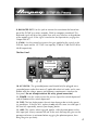
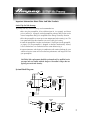
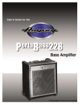
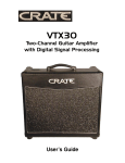
An Introduction to the Ampeg SVTMP:
The harmonically rich sound and legendary performance of AMPEG products
are redefined in the SVTMP. This rock-solid chunk of equipment is worth its weight
in gold on the stage, in the studio, or anywhere a quality microphone preamp is
needed. Some of the highlights of the SVTMP include:
• All tube design – one 12AX7, one 12AU7
• Transformer balanced Mic and Line inputs with up to 55dB of gain
• Hi-Z Instrument Input and Thru jacks
• Pad switches for each input – for the best signal to noise ratio and headroom
• Transformer balanced Output
The SVTMP will find its way into your life in a number of ways - as a mic preamp, as a line preamp/driver, or as an instrument preamp/DI to fatten up the sound
of your electric or acoustic/electric guitar, bass, keyboard, digital instrument, or
your PodTM, J-StationTM, or other processor .
Whether you use it to simply fatten up your instrument or drive a hundred feet
of cable, the SVTMP will deliver Ampeg tone and performance unlike any other it’s not just another brick in the wall - and, it will do it with that unmistakable touch
of AMPEG that will leave you floored.
CAUTION
PRECAUCION
ATTENTION
RISK OF ELECTRIC SHOCK
DO NOT OPEN
RIESGO DE CORRIENTAZO
NO ABRA
RISQUE D'ELECTROCUTION
NE PAS OUVRIR
WARNING: TO REDUCE THE RISK OF FIRE OR ELECTRIC
SHOCK, DO NOT EXPOSE THIS APPARATUS TO RAIN OR MOISTURE. TO REDUCE THE RISK OF ELECTRIC SHOCK, DO NOT
REMOVE COVER. NO USER-SERVICEABLE PARTS INSIDE.
REFER SERVICING TO QUALIFIED SERVICE PERSONNEL.
PRECAUCION: PARA REDUCIR EL RIESGO DE INCENDIOS O DESCARGAS
ELECTRICAS, NO PERMITA QUE ESTE APARATO QUEDE EXPUESTO A LA
LLUVIA O LA HUMEDAD. PARA DISMINUOIR EL RIESGO DE CORRIENTAZO.
NO ABRA LA CUBIERTA. NO HAY PIEZAS ADENTRO QUE EL USARIO PUEDO
REPARAR DEJE TODO MANTENIMIENTO A LOS TECHNICOS CALIFICADOS.
ATTENTION: PROTÉGEZ CET APPAREIL DE LA PLUIE ET DE L'HUMIDITÉ
AFIN D'ÉVITER TOUT RISQUE D'INCENDIE OU D'ÉLECTROCUTION. POUR
REDUIRE D'ELECTROCUTION NE PAS ENLEVER LE COUVERCLE. AUCUNE
PIECE INTERNE N'EST REPRABLE PAR L'UTILISATEUR. POUR TOUTE
REPARATION, S'ADRESSER A UN TECHNICIEN QUALIFIE.
IMPORTANT SAFETY INSTRUCTIONS
• READ, FOLLOW, HEED, AND KEEP ALL INSTRUCTIONS AND WARNINGS.
• DO NOT OPERATE NEAR ANY HEAT SOURCE AND DO NOT BLOCK ANY VENTILATION OPENINGS ON THIS APPARATUS. FOR PROPER OPERATION,
THIS UNIT REQUIRES 3” (75mm) OF WELL VENTILATED SPACE AROUND HEATSINKS AND OTHER AIR FLOW PROVISIONS IN THE CABINET.
• DO NOT USE THIS APPARATUS NEAR SPLASHING, FALLING, SPRAYING, OR STANDING LIQUIDS.
• CLEAN ONLY WITH LINT-FREE DAMP CLOTH AND DO NOT USE CLEANING AGENTS.
• ONLY CONNECT POWER CORD TO A POLARIZED, SAFETY GROUNDED OUTLET WIRED TO CURRENT ELECTRICAL CODES AND COMPATIBLE WITH
VOLTAGE, POWER, AND FREQUENCY REQUIREMENTS STATED ON THE REAR PANEL OF THE APPARATUS.
• PROTECT THE POWER CORD FROM DAMAGE DUE TO BEING WALKED ON, PINCHED, OR STRAINED.
• UNPLUG THE APPARATUS DURING LIGHTNING STORMS OR WHEN UNUSED FOR LONG PERIODS OF TIME.
• ONLY USE ATTACHMENTS, ACCESSORIES, STANDS, OR BRACKETS SPECIFIED BY THE MANUFACTURER FOR SAFE OPERATION AND TO AVOID INJURY.
• WARNING: TO REDUCE THE RISK OF ELECTRIC SHOCK OR FIRE, DO NOT EXPOSE THIS UNIT TO RAIN OR MOISTURE.
• SERVICE MUST BE PERFORMED BY QUALIFIED PERSONNEL.
• OUR AMPLIFIERS ARE CAPABLE OF PRODUCING HIGH SOUND PRESSURE LEVELS. CONTINUED EXPOSURE TO HIGH SOUND PRESSURE LEVELS
CAN CAUSE PERMANENT HEARING IMPAIRMENT OR LOSS. USER CAUTION IS ADVISED AND EAR PROTECTION IS RECOMMENDED IF UNIT IS
OPERATED AT HIGH VOLUME.
• WARNING: THIS UNIT REQUIRES A SAFETY GROUNDED OUTLET WIRED TO CURRENT ELECTRIC CODES HAVING THE LINE SUPPLY VOLTAGE,
POWER, AND FREQUENCY IDENTIFIED ON THE REAR OF THE UNIT. THE OUTLET MUST REMAIN ACCESSIBLE TO DISCONNECT THE UNIT IF A
FAULT SHOULD ARISE WHILE IN USE. THIS UNIT SHOULD BE UNPLUGGED WHEN NOT IN USE.
EXPLANATION OF GRAPHICAL SYMBOLS:
EXPLICACION DE SIMBOLOS GRAFICOS:
EXPLICATION DES SYMBÔLES GRAPHIQUES:
"DANGEROUS VOLTAGE"
=
“VOLTAJE PELIGROSO”
"DANGER HAUTE TENSION"
"IT IS NECESSARY FOR THE USER TO REFER TO THE INSTRUCTION MANUAL"
=
“ES NECESARIO QUE EL USUARIO SE REFIERA AL MANUAL DE INSTRUCCIONES.”
"REFERREZ-VOUS AU MANUAL D'UTILISATION"
Pod TM & J-Station TM are registered trademarks of Line 6 & Johnson Amplification, respectively
Features:
• COMBINATION XLR/1/4” INPUT JACK: Transformer balanced microphone input
on XLR connector, transformer balanced Line input on 1/4” T/R/S connector.
• INSTRUMENT INPUT JACKS: Allows connection of an instrument by means of a
standard 1/4” plug
• THRU JACK: Allows simultaneous connection to your stage amplifier
• PAD SWITCHES: Attenuate the input signal at the Mic/Line or Instrument Input jacks
to accommodate a wide variety of sources - output pad attenuation allows for optimum compatibility with mixers, tape machines, DAW’s, and computer sound cards
• PHASE REVERSE SWITCH: Allows you to invert the phase of the input signal
when needed
• GAIN CONTROL: Allows you to add up to 55dB of tube gain to the signal
• TRANSFORMER BALANCED OUTPUT: The high quality XLR connector uses a
custom designed transformer to provide the ultimate balanced output signal
• AMPEG QUALITY AND COSMETICS: Lets the world know you mean business
The Front Panel . . . . . . . . . . . . . . . . . . . . . . . . . 4-5
The Rear Panel . . . . . . . . . . . . . . . . . . . . . . . . . . . 5
Important Information About Tubes
And Tube Products . . . . . . . . . . . . . . . . . . . . . . . 6-7
System Block Diagram . . . . . . . . . . . . . . . . . . . . . . 7
Technical Specifications . . . . . . . . . . . . . . back cover
Declaration of Conformity
Manufacturer’s Name: SLM Electronics
Corporate Headquarters: 1901 Congressional Drive, St. Louis, Missouri 63146
Primary Production Facility: 700 Hwy 202 W, Yellville, Arkansas, 72687
Product Type: Audio Amplifier
Products meet the regulations for compliance marking under:
ETL standards UL6500, UL60065, or UL813
CSA standards E60065 or C22.2 No.1-M90
CE safety standard EN60065
CE EMC standards EN55103 or EN55013 and EN61000
FCC standards 47CFR 15.107 and 15.109 Class A
C-tick designation Level 2, ABN #56748810738, ARBN# N222
KETI standard K60065 (limited model approval)
Compliance Support Contact: SLM Electronics, Attn: R&D Compliance Engineer
1901 Congressional Drive, St Louis, Missouri, 63146 • Tel.: 314-569-0141, Fax: 314-569-0175
3
The Front Panel:
9
1
2
3
4
5
6
7
8
1. MIC/LINE: Connect a mic input signal to the balanced XLR jack by means
of a high quality shielded cable. This input is designed for mic input sources
only. Connect a balanced line signal to the inner 1/4” T/R/S jack. This jack is
designed to accept balanced line level signals.
2. PAD: This switch, when depressed, attenuates the signals at the XLR mic
input and the 1/4" T/R/S Line input by 20 dB and 10 dB respectively.
3. PHASE REVERSE: This switch, when depressed, reverses the phase of the
balanced mic and line signals. This switch can be used to correct phase
anomalies that may occur in multiple mic setups.
4. INSTRUMENT INPUT: Connect a bass, guitar, keyboard, etc. to this high
impedance 1/4” jack by means of a high quality shielded cable. This input has
a very high impedance to avoid any loading problems with your instrument
and is particularly well suited for acoustic instruments with piezo pickups.
5. THRU: Use this jack to connect the signal applied to the Instrument Input
jack (#4) directly to the input of your stage amplifier. The signal at the Thru
jack is taken directly from the instrument input signal and is not affected by
any switch setting or internal circuitry of the SVTMP. When using this jack,
you may also simultaneously send a balanced line signal to the FOH console
or other mixer.
6. PAD: This switch, when depressed, attenuates the signal applied to the
Instrument Input jack by 12 dB. The signal at the Thru jack is unaffected by
the setting of this switch. For the cleanest signal possible, do not engage this
switch when using the Mic/Line input jack (#1).
7. OUTPUT PAD: This switch, when depressed, attenuates the output signal
of the SVTMP by 20 dB
4
8. BALANCED OUT: Use this jack to connect the transformer balanced output of the SVTMP to a mixer, recorder, DAW or computer soundcard. This
balanced signal will drive long cable lines with very little loss or degradation
of the output signal. (If the signal is too hot for the input device, engage the
Output Pad (#7).
9. (GAIN): Use this control to increase the gain applied to the signals at the
XLR mic input and the 1/4" T/R/S Line input by 35 dB to 55 dB and 25 dB to
40 dB respectively.
The Rear Panel:
10
11 12
13
10. AC LINE IN: The grounded power cord should only be plugged into a
grounded power outlet that meets all applicable electrical codes and is compatible with the voltage, power and frequency requirements stated on the
rear panel. Do not attempt to defeat the safety ground connection!
11. POWER: Use this switch to turn the unit on (top of the switch depressed)
and off (bottom of the switch depressed).
12. FUSE: The fuse helps protect the unit from damage due to faulty operating conditions. If the fuse fails, replace it only with the same size and type. If
the fuse fails repeatedly, contact your Ampeg dealer.
13. +48V: This switch, when engaged, applies +48V phantom power to the
Mic input jack. Always connect the mic to the unit and keep the gains on the
preamp and mixer at minimum before engaging the phantom power, then
bring the gains up slowly.
5
Important Information About Tubes And Tube Products:
A Brief History Of The Tube:
In 1883, Edison discovered that electrons would flow from a suspended filament when enclosed in an evacuated lamp. Years later, in 1905, Fleming expanded on Edison's discovery and created the "Fleming Valve". Then,
in 1907, Dr. Lee de Forest added a third component – the grid – to the "Fleming's Valve" and the vacuum tube
was a fact of life. The door to electronic amplification was now open.
During World War II, data gleaned from their intensive research on the detectors used in radar systems led Bell
Telephone Laboratories to the invention of the transistor. This reliable little device gained quick support as the
new component for amplification. The death of the vacuum tube seemed imminent as designers, scientists, and
engineers reveled in the idea of replacing large, fragile glass tubes with these small, solid-state devices.
However, there were (and still are) many serious listeners who realized that the sound produced by a "transistor" amplifier is significantly different from that produced by a tube amplifier with identical design specifications. They considered the sound produced by these new solid-state devices to be hard, brittle, and lifeless. It
was determined that solid-state devices produced a less musical set of harmonics than tubes. When pushed
past their limits, they tend to mute the tone and emphasize the distortion.
Tubes, on the other hand, produce a more musical set of harmonics, the intensity of which can be controlled
by the player. This characteristic adds warmth and definition to the sound which has become the hallmark of
tube amplifiers. When tubes are driven into clipping, the harmonic overtones can be both sweet and pleasing
or intense and penetrating, depending on the musician’s musical taste and playing technique.
Over the years, application engineers have designed a number of outstanding solid-state amplifiers that sound
very, very good. Some use special circuitry which enables them to simulate the distortion characteristics of a
tube amplifier. However, the tube amplifier, still held in the highest esteem by many musicians, offers a classic
"vintage" sound in a contemporary market.
Preamplifier Tube types And Usage:
The tubes used in preamplifiers (12AX7, 12AU7, 12AT7, etc.) amplify the signal from your instrument and
shape the sound. They are inherently microphonic (mechanically pick up and transmit external noises). Since
these tubes are used in the critical first stages of a tube preamplifier's circuitry, it is very important to use highquality, low noise/low microphonic tubes for this application. Although tubes of this quality may be difficult to
find and typically cost more than "off-the-shelf" tubes, the improvement in performance is worth the investment.
The Nature Of Tubes: Why (And When) To Replace Them:
Tubes are made up of a number of fragile mechanical components that are vacuum-sealed in a glass envelope
or bubble. The tube's longevity is based on a number of factors which include how hard and often the equipment is played, vibration from the speakers, road travel, repeated set up and tear down, etc.
If your preamplifier squeals, makes noise, loses gain, starts to hum, lacks "sensitivity", or feels as if it is working
against you, the preamplifier tubes may need to be replaced. Remember to use only high quality, low microphonic tubes.
If you're on the road a lot, we recommend that you carry a set of replacement tubes.
6
Important Information About Tubes And Tube Products:
Survival Tips For Tube Preamps:
To prolong tube life, observe these tips and recommendations:
• After using the preamplifier, allow sufficient time for it to properly cool down
prior to moving it. A properly cooled preamplifier prolongs tube life due to the
internal components being less susceptible to the damage caused by vibration.
• Allow the preamplifier to warm up to room temperature before turning it on. The
heat generated by the tube elements can crack a cold glass housing.
• Protect the preamplifier from dust and moisture. If liquid gets into the preamplifier proper, or if the preamplifier is dropped or otherwise mechanically abused,
have it checked out at an authorized service center before using it.
• Proper maintenance and cleaning in combination with routine checkups by your
authorized service center will insure the best performance and longest life from
your preamplifier.
CAUTION: Tube replacement should be performed only by qualified service
personnel who are familiar with the dangers of hazardous voltages that are
typically present in tube circuitry.
System Block Diagram:
+48V
PAD
PHASE
REVERSE
INSTRUMENT
INPUT
MIC
THRU
LINE
OUTPUT
PAD
PAD
BALANCED
OUT
GAIN
7
TECHNICAL SPECIFICATIONS:
FREQ RESPONSE
20–20kHz, +/- 1dB
MAXIMUM OUTPUT LEVEL
+20dBm
INPUT IMPEDANCE
Mic (XLR)
Line (1/4” TRS)
Instrument (1/4”)
2k ohms
100k ohms
3M ohms
OUTPUT IMPEDANCE
600 ohms
DISTORTION
0.08%
DYNAMIC RANGE
>100dB (20-20kHz)
GAIN
Mic (XLR)
55dB max / 35dB min; 20dB pad
Line (1/4” TRS)
14dB max / -6dB min; 10dB pad
Instrument (1/4”)
45dB max / 25dB min; 12dB pad
NOISE
-80dBm
TUBES
(1) 12AX7, (1) 12AU7
POWER REQUIREMENTS
120V, 60Hz, 30VA
100V, 50/60Hz, 30VA
230V, 50Hz, 30VA
240V, 50Hz, 30VA
DIMENSIONS
3.25” H x 5.25” W x 8.5” D
WEIGHT
5 lbs.
Ampeg continually develops new products, as well as improves existing ones. For this reason,
the specifications and information in this manual are subject to change without notice.
www.ampeg.com
©2004 AMPEG, 1400 Ferguson Avenue, St. Louis, MO 63113 U.S.A.
47-339-02 • 121604