1
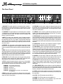
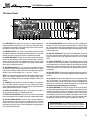
User’s Guide
for the
SVT1000
Bass Amplifier
Made with Pride in the U.S.A. by
SVT1000 Bass Amplifier
TABLE OF CONTENTS
Introduction . . . . . . . . . . . . . . . . . . . . . . . . . . . . . . . . . . . .3
Features . . . . . . . . . . . . . . . . . . . . . . . . . . . . . . . . . . . . . .3
The Front Panel . . . . . . . . . . . . . . . . . . . . . . . . . . . . . . . .4
The Rear Panel . . . . . . . . . . . . . . . . . . . . . . . . . . . . . . . . .5
Some Suggested Settings . . . . . . . . . . . . . . . . . . . . . . . . .6
Troubleshooting . . . . . . . . . . . . . . . . . . . . . . . . . . . . . . . .7
System Block Diagram . . . . . . . . . . . . . . . . . . . . . . . . . . .7
Technical Specifications . . . . . . . . . . . . . . . . . . .back cover
Declaration of Conformity
Manufacturer’s Name: SLM Electronics
Corporate Headquarters: 1901 Congressional Drive, St. Louis, Missouri 63146
Primary Production Facility: 700 Hwy 202 W, Yellville, Arkansas, 72687
Product Type: Audio Amplifier
Products meet the regulations for compliance marking under:
ETL standards UL6500, UL60065, or UL813
CSA standards E60065 or C22.2 No.1-M90
CE safety standard EN60065
CE EMC standards EN55103 or EN55013 and EN61000
FCC standards 47CFR 15.107 and 15.109 Class A
C-tick designation Level 2, ABN #56748810738, ARBN# N222
KETI standard K60065 (limited model approval)
Compliance Support Contact: SLM Electronics, Attn: R&D Compliance Engineer
1901 Congressional Drive, St Louis, Missouri, 63146 • Tel.: 314-569-0141, Fax: 314-569-0175
CAUTION
PRECAUCION
ATTENTION
RISK OF ELECTRIC SHOCK
DO NOT OPEN
RIESGO DE CORRIENTAZO
NO ABRA
RISQUE D'ELECTROCUTION
NE PAS OUVRIR
WARNING: TO REDUCE THE RISK OF FIRE OR ELECTRIC SHOCK, DO NOT EXPOSE
THIS APPARATUS TO RAIN OR MOISTURE. TO REDUCE THE RISK OF ELECTRIC
SHOCK, DO NOT REMOVE COVER. NO USER-SERVICEABLE PARTS INSIDE. REFER
SERVICING TO QUALIFIED SERVICE PERSONNEL.
PRECAUCION: PARA REDUCIR EL RIESGO DE INCENDIOS O DESCARGAS ELECTRICAS, NO PERMITA QUE ESTE APARATO QUEDE EXPUESTO A LA LLUVIA O LA HUMEDAD. PARA DISMINUOIR EL
RIESGO DE CORRIENTAZO. NO ABRA LA CUBIERTA. NO HAY PIEZAS ADENTRO QUE EL USARIO
PUEDO REPARAR DEJE TODO MANTENIMIENTO A LOS TECHNICOS CALIFICADOS.
ATTENTION: PROTÉGEZ CET APPAREIL DE LA PLUIE ET DE L'HUMIDITÉ AFIN D'ÉVITER TOUT
RISQUE D'INCENDIE OU D'ÉLECTROCUTION. POUR REDUIRE D'ELECTROCUTION NE PAS ENLEVER
LE COUVERCLE. AUCUNE PIECE INTERNE N'EST REPRABLE PAR L'UTILISATEUR. POUR TOUTE
REPARATION, S'ADRESSER A UN TECHNICIEN QUALIFIE.
IMPORTANT SAFETY INSTRUCTIONS
• READ, FOLLOW, HEED, AND KEEP ALL INSTRUCTIONS AND WARNINGS.
• DO NOT OPERATE NEAR ANY HEAT SOURCE AND DO NOT BLOCK ANY VENTILATION OPENINGS ON THIS APPARATUS. FOR PROPER OPERATION, THIS UNIT REQUIRES 3”
(75CM) OF WELL VENTILATED SPACE AROUND HEATSINKS AND OTHER AIR FLOW PROVISIONS IN THE CABINET.
• DO NOT USE THIS APPARATUS NEAR SPLASHING, FALLING, SPRAYING, OR STANDING LIQUIDS.
• CLEAN ONLY WITH LINT-FREE DAMP CLOTH AND DO NOT USE CLEANING AGENTS.
• ONLY CONNECT POWER CORD TO A POLARIZED, SAFETY GROUNDED OUTLET WIRED TO CURRENT ELECTRICAL CODES AND COMPATIBLE WITH VOLTAGE, POWER, AND
FREQUENCY REQUIREMENTS STATED ON THE REAR PANEL OF THE APPARATUS.
•
•
•
•
•
•
PROTECT THE POWER CORD FROM DAMAGE DUE TO BEING WALKED ON, PINCHED, OR STRAINED.
UNPLUG THE APPARATUS DURING LIGHTNING STORMS OR WHEN UNUSED FOR LONG PERIODS OF TIME.
ONLY USE ATTACHMENTS, ACCESSORIES, STANDS, OR BRACKETS SPECIFIED BY THE MANUFACTURER FOR SAFE OPERATION AND TO AVOID INJURY.
WARNING: TO REDUCE THE RISK OF ELECTRIC SHOCK OR FIRE, DO NOT EXPOSE THIS UNIT TO RAIN OR MOISTURE.
SERVICE MUST BE PERFORMED BY QUALIFIED PERSONNEL.
OUR AMPLIFIERS ARE CAPABLE OF PRODUCING HIGH SOUND PRESSURE LEVELS. CONTINUED EXPOSURE TO HIGH SOUND PRESSURE LEVELS CAN CAUSE PERMANENT HEARING IMPAIRMENT OR LOSS. USER CAUTION IS ADVISED AND EAR PROTECTION IS RECOMMENDED IF UNIT IS OPERATED AT HIGH VOLUME.
EXPLANATION OF GRAPHICAL SYMBOLS:
EXPLICACION DE SIMBOLOS GRAFICOS:
EXPLICATION DES SYMBÔLES GRAPHIQUES:
"DANGEROUS VOLTAGE"
=
“VOLTAJE PELIGROSO”
"DANGER HAUTE TENSION"
"IT IS NECESSARY FOR THE USER TO REFER TO THE INSTRUCTION MANUAL"
=
“ES NECESARIO QUE EL USUARIO SE REFIERA AL MANUAL DE INSTRUCCIONES.”
"REFERREZ-VOUS AU MANUAL D'UTILISATION"
SVT1000 Bass Amplifier
An Introduction to your new Ampeg SVT1000 Bass Amplifier
Thank you for making one of the best choices you will ever make for your musical career – choosing one of the
finest bass amps available, the Ampeg SVT1000. This versatile and powerful bass amplifier delivers up to 1350
watts of unsurpassed musical power, and offers several outstanding features.
All of the features and controls of your SVT1000 are covered in detail within the pages of this user’s guide. We
recommend that you read this guide and understand them before you use the amplifier.
Features
In the world of high performance bass amps, Ampeg amplifiers stand alone. In true Ampeg tradition, the
SVT1000 offers you more power, performance and flexibility than any other bass amplifier in its class. The outstanding features of your new amplifier, features which set it apart from the competition, are listed below.
• 5-POSITION STYLE CONTROL: Take your pick from five different tone variations to best suit your
playing style
• TEXTURE CONTROL: Ampeg’s exclusive “tube emulation” circuit which changes the tone for a
more aggressive sound
• 9-BAND GRAPHIC EQ: Switchable at front panel or with a footswitch, you can use this as a “second channel” for bass solos, or to shape your sound to your own exacting standards - an independent level control lets you adjust the Graphic EQ volume
• EFFECTS MIX: Varies the amount of external effects mixed into the signal
• TUNER OUT JACK: Allows connection to an electronic tuner and provides an “always live” monitor
feed even when the output is muted
• HEAVY-DUTY SPEAKER JACKS: Speakon® jacks for more reliable connections at higher output
• BALANCED AND UNBALANCED LINE OUTPUTS: Independent level control - balanced XLR and
unbalanced 1/4” output jacks - switchable pre or post EQ - ground lift for balanced XLR
• EFFECTS LOOP: Connect external effects here for increased intensity and quieter operation
• POWER AMP IN/PREAMP OUT: A separate preamp may be connected to the Power Amp In jack,
and the Preamp Out jack may be connected to a slave amp
• FOOTSWITCH CONTROL: Use a footswitch to activate the Graphic EQ and the Mute feature
• CIRCUIT BREAKER PROTECTION: A heavy duty resettable circuit breaker provides protection
against fault conditions
Speakon® is a registered trademark of Neutrik AG.
3
SVT1000 Bass Amplifier
The Front Panel
+12dB
Gain
Input
Mute
4
5
Style
3
1
2 3 4
6
4
7
5
9
0
10
Treble
6
3
4
7
82
1
10
Texture
5
2
8
9
0
-15dB
15dB
4
Ultra Mid
3
7
1
0dB
12345
6
2
Bass
5
6
3
9
0
10
10
6
Dry
Wet
8
9
10
7
Power
0
8
9
0
11 12 13
Power
6
1
Limit
Defeat
7
5
3
9
0
4
2
8
1
Peak
5
Master
Graphic
EQ
7
82
1
Effects
Mix
-12dB
12dB
10
Limit
14 15
33Hz
80Hz
150Hz 300Hz 600Hz 900Hz
16
2kHz
5kHz
8kHz
Level
Active
17 18 19
20
1. 0dB INPUT: The signal output from an instrument (active or passive –
typically passive) or a line level signal may be connected here by means
of a shielded instrument cable. The signal at this jack is sent into the preamp at full amplitude.
9. ULTRA MID: Use this control to adjust the midrange frequency level of
the amplifier. This control provides 7dB of cut (fully counterclockwise) at
400Hz or boost (fully clockwise) at 800Hz. The midrange frequency output
is flat at the center position.
2. -15dB INPUT: The signal output from an instrument (active or passive
– typically active) or a line level signal may be connected here by means
of a shielded instrument cable. The signal at this jack is padded 15dB
before it is sent into the preamp.
10. TREBLE: Use this control to adjust the high frequency level of the
amplifier. This control provides 18dB of cut or boost at 5kHz. The high frequency output is flat at the center position.
3. MUTE: This switch, when depressed, mutes all outputs except the
Tuner Out (#25). A footswitch can also control muting if the Mute switch on
the front panel is left in the “out” position. (The front panel switch stays
active with a footswitch connected.) This is excellent for tuning your bass
with an electronic tuner without having to adjust any levels or turn down
your house volume.
4. TEXTURE: This switch adds a “tube emulation” stage which changes
the tone for a more aggressive sound. Using the Texture switch, you can
overdrive the amplifier without typical (and harsh-sounding) solid state clipping.
5. GAIN: Use this control to adjust the level of the signal entering the preamp stage. Adjust this control until the Peak LED (#6) flashes on strong
signal peaks (but is not illuminated constantly while playing). To obtain the
best signal to noise ratio, set the Gain control as described above and
adjust the Master (#14) to obtain the desired volume level.
6. PEAK LED: This LED will illuminate when the signal entering the preamp stage is near the clipping level. Adjust the Gain control (#5) until a
strong signal from your instrument causes this LED to flash.
7. STYLE: Use this five-position switch to vary the tone of the amplifier.
The following table lists each of the different settings – experiment with the
Style and other EQ controls for the results which suit you best.
POSITION 1:
POSITION 2:
POSITION 3:
POSITION 4:
POSITION 5:
Fully “scooped” mids (mid cut)
Traditional passive tone setting
Basically flat
Boosted high end
Basically flat with low end roll off – for loud playing without “muddiness”
8. BASS: Use this control to adjust the low frequency level of the amplifier. This control provides 12dB of cut or boost at 50Hz. The low frequency
output is flat at the center position.
11. EFFECTS MIX: This control varies the mix between the direct (dry) signal and the effects (wet) when the effects loop (#26,27) is used. Full counterclockwise results in all direct signal (no effect) and full clockwise gives
all effect and no direct signal. The fully clockwise position is equivalent to
a series effects loop and should be used with such devices as limiters and
equalizers.
12. GRAPHIC EQ: This switch, when depressed, activates the graphic
equalizer. When a footswitch is used, this switch is disabled.
13. LIMIT DEFEAT: The SVT1000 employs internal limiter circuits to help
keep the power amplifier’s output clean at extreme volume levels. (All
amplifiers may begin to clip their output signals as they approach maximum output levels, resulting in potentially speaker-damaging distortion.)
These circuits may be disabled by depressing this switch. This may result
in an increase in output power, but also increases the possibility of distortion. Use discretion whenever playing with the Limit circuits off.
14. MASTER: Use this control to adjust the overall output level of the
amplifier. For the lowest possible noise level, adjust the Gain control as
described in #5 and use this control to obtain the desired volume level.
15. LIMIT LED: This LED illuminates when the internal limit circuit is called
upon to keep the amplifier’s output signal clean. This indicates that the
amplifier is nearing full output and the limiter is keeping it from clipping the
output signal.
16. 9-BAND GRAPHIC EQ: Use these sliders to control the amplitude of
the frequencies indicated above each control. The center position of each
control is flat: sliding the control upward will increase the output level of that
frequency; sliding the control downward will decrease it.
17. LEVEL: Use this slider to adjust the output level of the Graphic EQ. If
the EQ’d signal is too soft, slide the Level control up; if it’s too loud, slide
the control down.
18. ACTIVE: This LED illuminates when the EQ is on.
19. POWER: This LED illuminates when the amplifier is on.
20. POWER: Use this switch to turn the amplifier on (top of the switch
depressed) and off (bottom of the switch depressed).
SVT1000 Bass Amplifier
The Rear Panel
21
22
23
24
7
43565 15531
9
SVT1000
(21) SERIAL# BMCDN20083
Line: 120V Freq: 60 Pwr: XXXVA
25
26
27
28
29 30 31
32
21. FOOTSWITCH: Use this jack to connect a two button footswitch for
remote Mute and EQ On/Off control. (Tip = Mute, ring = EQ On/Off.) When
a footswitch is connected, the Mute switch (#3) remains active; however,
the Graphic EQ switch (#12) is disabled.
22. PREAMP OUTPUT: This jack is a direct preamp output for use with
external power amplifiers, mixing boards, external effects, etc. Connect the
external unit’s input to this jack by means of a shielded signal cable.
23. POWER AMP INPUT: This jack connects directly to the power amp for
use with an external preamp. When using an external source, connect its
output to this jack by means of a shielded signal cable to feed the signal
into the power amp section. The amplifier’s input signal is disconnected
when a plug is inserted into this jack.
24. SPEAKER OUTPUTS: The 1/4” jacks offer a convenient method of
connecting to speaker cabinets using cables terminated with 1/4” plugs.
However, when using the amplifier at or near its full output power, using the
Speakon® jacks is recommended. (Pin 1+ = hot, pin 1- = return.)
NOTE: This amp is internally hard wired for bridge mode operation. Do not
remove the insulating washers from the 1/4” Speaker Output jacks.
Removing the insulating washers will damage the amplifier and void your
warranty.
25. TUNER OUT: Use this jack to connect the amplifier to an electronic
tuner. The signal at this jack is always “live,” even when the Mute switch
(#3) is engaged, allowing for “silent tuning” as well as a monitor feed which
remains active when the house mix is muted.
26. EFFECTS LOOP SEND: Use this jack to sent a signal to the input of
an external effect by means of a shielded signal cable.
27. EFFECTS LOOP RETURN: Use this jack to connect the output signal
from an external effect to the amplifier by means of a shielded signal cable.
28. LINE OUT UNBALANCED: Use this 1/4” jack to send an unbalanced
line level signal to a house mixing board, recording console, or external
amplifier. The signal level at this jack is controlled by the Line Out Level
control (#32) and may be Pre or Post-EQ depending on the setting of the
Line Out Pre/Post switch (#31).
33
34
29. LINE OUT BALANCED: Use this XLR jack to send a balanced line
level signal to a house mixing board, recording console, or external amplifier. The signal level at this jack is controlled by the Line Out Level control
(#32) and may be Pre or Post-EQ depending on the setting of the Line Out
Pre/Post switch (#31).
30. LINE OUT GROUND LIFT: This switch, when depressed, disconnects
the ground connection at the Balanced Line Out jack (#29). This may help
reduce residual hum and buzz sometimes picked up in line out signal
cables.
31. LINE OUT PRE/POST: This switch, when depressed, sends a PostEQ signal to the Line Out jacks (#28,29). The Post-EQ signal is modified
by the settings of the tone controls, Graphic Eq and effects loop. With the
switch in the out position, the signal sent to the Line Out jacks is Pre-EQ.
The Pre-EQ signal is a direct output and is not affected by any of the preamp settings.
32. LINE OUT LEVEL: Use this control to adjust the signal level at the Line
Out jacks (#28,29). This control works independently from the Master control (#14).
33. AC LINE IN: Firmly insert the supplied AC power cord into this socket
until it is fully seated. This grounded power cord is to be plugged into a
grounded power outlet, wired to current electric codes and compatible with
voltage, power, and frequency requirements stated on the rear panel. Do
no attempt to defeat the safety ground connection.
34. CIRCUIT BREAKER: The SVT1000 employs an AC line circuit breaker to help protect against damage due to excessive current demands. If the
amplifier stops working, check the circuit breaker. If it has opened, the button will be protruding and showing a contrasting color. You can reset the
circuit breaker by pushing it in until it latches. The breaker must cool down
for a short time before the button will latch. If the circuit breaker opens
repeatedly, have the amplifier checked by a qualified service person.
IMPORTANT NOTE: This unit employs forced air cooling by
means of an internal fan system. The front and rear ventilation
slots must remain unobstructed when operating this amplifier.
5
SVT1000 Bass Amplifier
Some Suggested Settings
Since so many variables
affect the actual sound of any
system, the following settings are
offered as starting points to help
you find the exact sounds your
playing demands. When using
the SVT1000, please keep in
mind the following points:
ROCK:
• The Gain control should be
adjusted until the peak LED
flashes on strong signals. (This
level will vary, depending on
your instrument and playing
style.)
JAZZ:
• The Master control should be
set to produce the appropriate
output volume level.
GAIN
STYLE
BASS
ULTRA MID
TREBLE
STYLE
BASS
ULTRA MID
TREBLE
STYLE
BASS
ULTRA MID
TREBLE
STYLE
BASS
ULTRA MID
TREBLE
STYLE
BASS
ULTRA MID
TREBLE
MUTE
IN
TEXTURE
PEAK
GAIN
MUTE
OUT
TEXTURE
COUNTRY:
PEAK
GAIN
MUTE
• The Graphic EQ can be used
to further fine-tune these basic
suggested setting, to extend
the frequency response of the
cabinet being used, to compensate for room acoustics, or
to act like a “second channel.”
IN
OUT
TEXTURE
BRIGHT:
PEAK
GAIN
MUTE
OUT
IN
TEXTURE
FUNK “POPPING:”
PEAK
GAIN
MUTE
IN
OUT
TEXTURE
6
PEAK
SVT1000 Bass Amplifier
Troubleshooting
In the unlikely event that your SVT1000 should malfunction, take a few minutes to troubleshoot it before you call for
service. You can save yourself time and money by doing it yourself, and often the problem is something quite simple.
NO SOUND
POOR SOUND
LEDs LIGHT
LEDs DON'T LIGHT
Check bass, cables
Check amp controls, check
for signal from bass
Check AC outlet
POOR SOUND
OUTLET OK NO POWER
Check speaker(s)
NO SOUND
SOUND OK
SOUND OK
Check power cord,
fuse, power switch
Listen for hum
NO HUM
HUM
Check speaker
Unplug bass,
touch tip of cable
Check house fusebox
or circuit breaker
SPEAKER(S) OK,
POOR SOUND
OK
SPEAKER(S)
DEFECTIVE
Replace speaker(s)
POOR SOUND
SOUND OK
Speaker OK
NO CHANGE
SOUND OK
Replace cable
NO CHANGE
SEE BELOW
SEE BELOW
If the problem isn’t covered above, or if the steps lead you here, then contact your Ampeg dealer for service information. Also, you should refer your amp to an authorized service center if it gets dropped, has liquid spilled into it, or sustains
damage to its power cord. Regular cleaning and maintenance by your local Service Center will help extend the useful life
of the amplifier.
System Block Diagram
PEAK
LED
TEXTURE
TUNER
OUT
0dB
INPUT
TONE CIRCUITS
EQ IN
MUTE
GAIN
9 BAND
GRAPHIC
EQ
BASS ULTRA MID TREBLE
-15dB
INPUT
(X9)
f
STYLE
LEVEL
(SLIDERS)
LIMIT
LED
UNBAL
LINE OUT
PRE
BAL
LINE
OUT
LINE
POST OUT
PRE/
POST
LIMIT
DEFEAT
POWER
AMP
LIMITER
SPKR
OUT
1+
SPKR
OUT
1–
LEVEL
GROUND
LIFT
POWER
AMP IN
EFFECTS
SEND
SPEAKON ®
JACK
2–
SPEAKON
JACK
2+
PREAMP
OUT
MASTER
2–
1+
1–
®
2+
EFFECTS
MIX
EFFECTS
RETURN
Speakon® is a registered trademark of Neutrik AG.
7
SVT1000 Bass Amplifier
Technical Specifications
OUTPUT POWER RATING
1350 Watts @ 4 Ohms (1000 Watts Continuous)
840 Watts @ 8 Ohms (680 Watts Continuous)
TONE CONTROL RANGE
Bass:
Ultra Mid:
Treble:
GRAPHIC EQ LEVEL
GRAPHIC EQ RANGE
33Hz:
80Hz:
150Hz:
300Hz:
600Hz:
900Hz:
2kHz:
5kHz:
8kHz:
SIGNAL TO NOISE RATIO
FOOTSWITCH JACK
POWER REQUIREMENTS
Domestic:
Export:
SIZE AND WEIGHT
±12dB @ 50Hz
+7dB @ 800Hz, -7dB @400Hz
±18dB @ 5kHz
±6dB
±15dB
±10dB
±8dB
±8dB
±8dB
±8dB
±8dB
±10dB
±12dB
75dB typical
Graphic EQ On/Off, Mute On/Off – Tip = Mute, Ring = EQ
120VAC, 60Hz, 800VA
100VAC 50/60Hz, 800VA
230VAC, 50Hz, 800VA
240VAC, 50Hz, 800VA
24” W x 11-3/4” H x 14” D; 57 lbs
Ampeg reserves the right to change specifications without notice.
www.ampeg.com
Made with Pride in the U.S.A. by Ampeg • ©2004 Ampeg, 1400 Ferguson Avenue, St. Louis, MO 63133 U.S.A.
P/N 47-659-01 . 051904