1
IN S TAL L AT ION , OP E R AT IN G AN D
S E R V IC E IN S T R U C T ION S F OR
MP O
3 - PA S S O I L B O I L E R
As an
ENERGY STAR® Partner,
Burnham Hydronics
has determined that the
MPO84, MPO147, MPO189
and MPO231 meet the
ENERGY STAR®
guidelines for Energy
efficiency established by the
United States Environmental
Protection Agency (EPA).
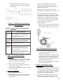
F o r s e r vi c e o r r e p a i r s to b o i le r, c a ll yo ur he a ti ng c o ntr a c to r o r o i l s up p li e r. W he n s e e k i ng
i nfo r m a ti o n o n b o i le r, p r o vi d e B o i le r M o d e l Num b e r a nd S e r i a l Num b e r a s s ho wn o n Ra ti ng
L a b e l lo c a te d o n to p o f the b o i le r.
B o i le r M o d e l Num b e r
MP O _ _ _ - _ _
He a ti ng C o ntr a c to r
B o i le r S e r i a l Num b e r
Ins ta lla ti o n D a te
6_ _ _ _ _ _ _
P ho ne Num b e r
A d d re s s
100103-01R3-10/05
Price - $3.00
IMPORTANT INFORMATION - READ CAREFULLY
All b o ile rs mu s t b e in s ta lle d in a c c o rd a n c e w ith N a tio n a l, S ta te a n d L o c a l P lu mb in g ,
H e a t in g a n d E le c t r ic a l C o d e s a n d t h e r e g u la t io n s o f t h e s e r v in g u t ilit ie s . T h e s e C o d e s
a n d R e g u la tio n s ma y d iffe r fro m th is in s tru c tio n ma n u a l. Au th o ritie s h a v in g
ju r i s d i c t i o n s h o u l d b e c o n s u l t e d b e f o r e i n s t a l l a t i o n s a r e m a d e .
In a ll c a s e s , r e f e r e n c e s h o u ld b e m a d e t o t h e f o llo w in g S t a n d a r d s :
U S A B OIL E R S
A. C u rre n t E d itio n o f Ame ric a n N a tio n a l S ta n d a rd AN S I/N F PA 3 1 , “ In s ta lla tio n o f Oil
B u r n in g E q u ip m e n t ” , f o r r e c o m m e n d e d in s t a lla t io n p r a c t ic e s .
B . C u r r e n t E d i t i o n o f A m e r i c a n N a t i o n a l S t a n d a r d A N S I / N F P A 2 11 , “ C h i m n e y s ,
F ire p la c e s , Ve n ts , a n d S o lid F u e l B u rn in g Ap p lia n c e s ” , F o r Ve n tin g re q u ire me n ts .
C. C u r r e n t E d itio n o f Am e r ic a n S o c ie ty o f Me c h a n ic a l E n g in e e r s AS ME C S D -1 ,
" C o n t r o ls a n d S a f e t y D e v ic e s f o r Au t o m a t ic a lly F ir e d B o ile r s " , f o r a s s e m b ly a n d
o p e r a t io n s o f c o n t r o ls a n d s a f e t y d e v ic e s .
D . All w irin g o n b o ile rs in s ta lle d in th e U S A s h a ll b e ma d e in a c c o rd a n c e w ith th e
N a t i o n a l E l e c t r i c a l C o d e a n d /o r L o c a l R e g u l a t i o n s .
C AN AD IAN B OIL E R S
A. C u rre n t E d itio n o f C a n a d ia n S ta n d a rd s As s o c ia tio n C S A B 1 3 9 , " In s ta lla tio n C o d e
f o r Oil B u r n in g E q u ip m e n t " , f o r r e c o m m e n d e d In s t a lla t io n P r a c t ic e s .
B . All w irin g o n b o ile rs in s ta lle d in C a n a d a s h a ll b e ma d e in a c c o rd a n c e w ith th e
C a n a d i a n E l e c t r i c a l C o d e a n d /o r L o c a l R e g u l a t i o n s .
The following terms are used throughout this manual to bring attention to the presence of hazards
of various risk levels, or to important information concerning product life.
CAUTION
DANGER
In d ic a t e s a n im m in e n t ly h a z a r d o u s
s it u a t io n w h ic h , if n o t a v o id e d , w ill r e s u lt
in d e a t h , s e r io u s in ju r y o r s u b s t a n t ia l
p ro p e rty d a ma g e .
In d ic a t e s a p o t e n t ia lly h a z a r d o u s
s it u a t io n w h ic h , if n o t a v o id e d , m a y r e s u lt
in m o d e r a t e o r m in o r in ju r y o r p r o p e r t y
d a ma g e .
NOTICE
WARNING
In d ic a t e s a p o t e n t ia lly h a z a r d o u s
s it u a t io n w h ic h , if n o t a v o id e d , c o u ld
r e s u lt in d e a t h , s e r io u s in ju r y o r
s u b s t a n t ia l p r o p e r t y d a m a g e .
In d ic a t e s s p e c ia l in s t r u c t io n s o n
in s t a lla t io n , o p e r a t io n , o r m a in t e n a n c e
w h ic h a r e im p o r t a n t b u t n o t r e la t e d t o
p e r s o n a l in ju r y h a z a r d s .
NOTICE
T h is b o ile r h a s a limite d w a rra n ty, a c o p y o f w h ic h is p rin te d o n th e b a c k o f th is ma n u a l.
T h e w a r r a n t y f o r t h is b o ile r is v a lid o n ly if t h e b o ile r h a s b e e n in s t a lle d , m a in t a in e d a n d
o p e r a t e d in a c c o r d a n c e w it h t h e s e in s t r u c t io n s .
S u r f a c e r u s t o n c a s t ir o n s e c t io n s m a y b e a t t r ib u t e d t o t h e m a n u f a c t u r in g p r o c e s s a s w e ll
a s c o n d e n s a t io n d u r in g s t o r a g e . S u r f a c e r u s t is n o r m a l a n d d o e s n o t a f f e c t t h e
p e r f o r m a n c e o r lo n g e v it y o f a b o ile r .
2
DANGER
D O N OT s t o r e o r u s e g a s o lin e o r o t h e r fla m m a b le v a p o r s o r liq u id s in t h e v ic in it y o f t h is o r
a n y o t h e r a p p lia n c e .
WAR N IN G
Im p r o p e r in s t a lla t io n , a d ju s t m e n t , a lt e r a t io n , s e r v ic e o r m a in t e n a n c e c a n c a u s e p r o p e r t y
d a m a g e , p e r s o n a l in ju r y o r lo s s o f lif e . F a ilu r e t o f o llo w a ll in s t r u c t io n s in t h e p r o p e r
o r d e r c a n c a u s e p e r s o n a l in ju r y o r d e a t h . R e a d a n d u n d e r s t a n d a ll in s t r u c t io n s ,
in c lu d in g a ll t h o s e c o n t a in e d in c o m p o n e n t m a n u fa c t u r e r s m a n u a ls w h ic h a r e p r o v id e d
w it h t h e a p p lia n c e b e fo r e in s t a llin g , s t a r t in g - u p , o p e r a t in g , m a in t a in in g o r s e r v ic in g t h is
a p p lia n c e . K e e p t h is m a n u a l a n d lit e r a t u r e in le g ib le c o n d it io n a n d p o s t e d n e a r
a p p lia n c e fo r r e fe r e n c e b y o w n e r a n d s e r v ic e t e c h n ic ia n .
T h is b o ile r r e q u ir e s r e g u la r m a in te n a n c e a n d s e r v ic e to o p e r a te s a fe ly. F o llo w th e
in s t r u c t io n s c o n t a in e d in t h is m a n u a l.
In s t a lla t io n , m a in t e n a n c e , a n d s e r v ic e m u s t b e p e r fo r m e d o n ly b y a n e x p e r ie n c e d ,
s k ille d a n d k n o w le d g e a b le in s ta lle r o r s e r v ic e a g e n c y.
Al l h e a t i n g s y s t e m s s h o u l d b e d e s i g n e d b y c o m p e t e n t c o n t r a c t o r s a n d o n l y p e r s o n s
k n o w le d g e a b le in t h e la y o u t a n d in s t a lla t io n o f h y d r o n ic h e a t in g s y s t e m s s h o u ld
a tte m p t in s ta lla tio n o f a n y b o ile r.
In s t a lla t io n is n o t c o m p le t e u n le s s a p r e s s u r e r e lie f v a lv e is in s t a lle d in t o t h e 3 /4 " t a p p in g lo c a t e d o n r e t u r n m a n ifo ld t h a t w a s in s t a lle d in t o b o s s o n t o p o f r e a r s e c t io n - S e e
P a c k a g e d B o ile r As s e m b ly - Tr im & C o n tr o ls a n d Wa te r B o ile r P ip in g S e c tio n s o f th is
m a n u a l fo r d e t a ils .
It is t h e r e s p o n s ib ilit y o f t h e in s t a llin g c o n t r a c t o r t o s e e t h a t a ll c o n t r o ls a r e c o r r e c t ly
in s t a lle d a n d a r e o p e r a t in g p r o p e r ly w h e n t h e in s t a lla t io n is c o m p le t e d .
T h is b o ile r is s u it a b le fo r in s t a lla t io n o n c o m b u s t ib le flo o r in g . D o n o t in s t a ll b o ile r o n
c a r p e t in g .
D o n o t t a m p e r w it h o r a lt e r t h e b o ile r o r c o n t r o ls .
In s p e c t flu e w a y s a t le a s t o n c e a y e a r - p r e fe r a b ly a t t h e s t a r t o f t h e h e a t in g s e a s o n .
T h e in s id e o f th e c o m b u s tio n c h a m b e r, th e v e n t s y s te m a n d b o ile r flu e w a y s s h o u ld b e
c le a n e d if s o o t o r s c a le h a s a c c u m u la t e d .
W h e n c le a n in g th is b o ile r, ta k e p r e c a u tio n to a v o id d a m a g e to b u r n e r s w in g d o o r
in s u la t io n . If d a m a g e d , o r if t h e r e is e v id e n c e o f p r e v io u s d a m a g e , b u r n e r s w in g d o o r
in s u la tio n m u s t b e r e p la c e d im m e d ia te ly.
Oil B u r n e r a n d C o n t r o ls m u s t b e c h e c k e d a t le a s t o n c e a y e a r o r a s m a y b e
n e c e s s it a t e d .
D o n o t o p e r a t e u n it w it h ju m p e r e d o r a b s e n t c o n t r o ls o r s a f e t y d e v ic e s .
D o n o t o p e r a t e u n it if a n y c o n t r o l, s w it c h , c o m p o n e n t , o r d e v ic e h a s b e e n s u b je c t t o
w a te r.
Ap p l i a n c e m a t e r i a l s o f c o n s t r u c t i o n , p r o d u c t s o f c o m b u s t i o n a n d t h e f u e l c o n t a i n
a lu m in a , s ilic a , h e a v y m e t a ls , c a r b o n m o n o x id e , n it r o g e n o x id e s , a ld e h y d e s a n d /o r
o t h e r t o x ic o r h a r m f u l s u b s t a n c e s w h ic h c a n c a u s e d e a t h o r s e r io u s in ju r y a n d w h ic h
a r e k n o w n to th e s ta te o f C a lifo r n ia to c a u s e c a n c e r, b ir th d e fe c ts a n d o th e r
r e p r o d u c t i v e h a r m . Al w a y s u s e p r o p e r s a f e t y c l o t h i n g , r e s p i r a t o r s a n d e q u i p m e n t
w h e n s e r v ic in g o r w o r k in g n e a r b y t h e a p p lia n c e .
3
WAR N IN G
T h is b o ile r c o n t a in s v e r y h o t w a t e r u n d e r h ig h p r e s s u r e . D o n o t u n s c r e w a n y p ip e
fit t in g s n o r a t t e m p t t o d is c o n n e c t a n y c o m p o n e n t s o f t h is b o ile r w it h o u t p o s it iv e ly
a s s u r i n g t h e w a t e r i s c o o l a n d h a s n o p r e s s u r e . Al w a y s w e a r p r o t e c t i v e c l o t h i n g a n d
e q u ip m e n t w h e n in s t a llin g , s t a r t in g u p o r s e r v ic in g t h is b o ile r t o p r e v e n t s c a ld in ju r ie s .
D o n o t r e ly o n t h e p r e s s u r e a n d t e m p e r a t u r e g a u g e s t o d e t e r m in e t h e t e m p e r a t u r e a n d
p r e s s u r e o f th e b o ile r. T h is b o ile r c o n ta in s c o m p o n e n ts w h ic h b e c o m e v e r y h o t w h e n
t h e b o ile r is o p e r a t in g . D o n o t t o u c h a n y c o m p o n e n t s u n le s s t h e y a r e c o o l.
T h is b o ile r m u s t b e p r o p e r ly v e n t e d . T h e c h im n e y m u s t b e in s p e c t e d fo r a n y
o b s t r u c t io n s a n d c le a n e d p r io r t o e a c h h e a t in g s e a s o n . A c le a n a n d u n o b s t r u c t e d
c h im n e y flu e is n e c e s s a r y t o p r o d u c e t h e m in im u m d r a ft r e q u ir e d t o s a fe ly e v a c u a t e
n o x io u s f u m e s t h a t c o u ld c a u s e p e r s o n a l in ju r y o r lo s s o f lif e . E v id e n c e o f lo o s e d e b r is
a n d o r c o n d e n s a t e in d u c e d s t a in s a t t h e b a s e o f t h e c h im n e y flu e , c o n n e c t o r o r
s m o k e p ip e jo in t s m a y b e s ig n s o f c o n d e n s in g f lu e g a s e s . F lu e g a s c o n d e n s a t e is
c o r r o s iv e , w h ic h r e q u ir e s s p e c ia l c o n s id e r a tio n a n d m u s t b e a d d r e s s e d im m e d ia te ly.
R e f e r t o S e c t i o n V, " Ve n t i n g a n d A i r I n t a k e P i p i n g " .
T h is b o ile r n e e d s fr e s h a ir fo r s a fe o p e r a t io n a n d m u s t b e in s t a lle d s o t h e r e a r e
p r o v is io n s fo r a d e q u a te c o m b u s tio n a n d v e n tila tio n a ir.
T h is b o ile r is s u p p lie d w it h c o n t r o ls w h ic h m a y c a u s e t h e b o ile r t o s h u t d o w n a n d n o t
r e -s ta r t w ith o u t s e r v ic e . If d a m a g e d u e to fr o z e n p ip e s is a p o s s ib ility, th e h e a tin g
s y s t e m s h o u ld n o t b e le ft u n a t t e n d e d in c o ld w e a t h e r ; o r a p p r o p r ia t e s a fe g u a r d s a n d
a la r m s s h o u ld b e in s t a lle d o n t h e h e a t in g s y s t e m t o p r e v e n t d a m a g e if t h e b o ile r is
in o p e r a t iv e .
T h is b o ile r is d e s ig n e d to b u r n N o . 2 fu e l o il o n ly. D o n o t u s e g a s o lin e , c r a n k c a s e
d r a in in g s , o r a n y o il c o n ta in in g g a s o lin e . N e v e r b u r n g a r b a g e o r p a p e r in th is b o ile r.
D o n o t c o n v e r t t o a n y s o lid fu e l ( i.e . w o o d , c o a l) . D o n o t c o n v e r t t o a n y g a s e o u s fu e l
(i.e . n a tu r a l g a s , L P ). All fla m m a b le d e b r is , r a g s , p a p e r, w o o d s c r a p s , e tc ., s h o u ld b e
k e p t c le a r o f t h e b o ile r a t a ll t im e s . K e e p t h e b o ile r a r e a c le a n a n d fr e e o f fir e h a z a r d s .
Al l b o i l e r s e q u i p p e d w i t h b u r n e r s w i n g d o o r h a v e a p o t e n t i a l h a z a r d w h i c h , i f i g n o r e d ,
c a n c a u s e s e v e r e p r o p e r t y d a m a g e , p e r s o n a l in ju r y o r lo s s o f lif e . B e f o r e o p e n in g
s w in g d o o r, u n p lu g b u r n e r p o w e r c o r d fr o m r e c e p ta c le lo c a te d in lo w e r r ig h t c o r n e r o f
ja c k e t f r o n t p a n e l a n d t u r n o f f s e r v ic e s w it c h t o b o ile r t o p r e v e n t a c c id e n t a l f ir in g o f
b u r n e r o u ts id e t h e c o m b u s tio n c h a m b e r. B e s u r e to tig h te n s w in g d o o r fa s te n e r s
c o m p le t e ly w h e n s e r v ic e is c o m p le t e d .
4
TA B L E O F C O N T E N T S
I. Pre-Installation .....................................
8
VIII. System Start-Up.....................................
35
II. Packaged Boiler Assy.- Trim & Control...
10
IX. Maintenance & Service Instuction ..........
43
III. Water Boiler Trim & Piping ......... ...........
21
X. Boiler Cleaning......................................
45
IV. Indirect Water Heater Piping..... ..............
25
XI . Trouble Shooting.................................. .
47
V. Venting ............................... .................
26
XII. Repair Parts...........................................
48
VI. Electrical...............................................
31
VII. Oil Piping..............................................
33
XIII. Appendix.
Low Water Cut Off.................................
60
5
6
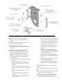
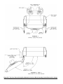
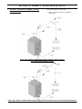
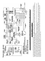
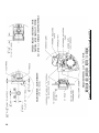
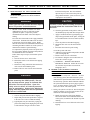
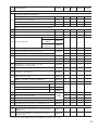
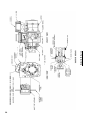
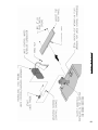
Figure 1: MPO 84 Thru MPO 231 Water Boiler
7
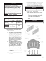
2 8 - 5 /8 "
3 4 - 5 /8 "
M P O1 8 9
M P O2 3 1
0 .6 0
1 .0 5
1 .3 5
1 .6 5
M P O8 4
M P O1 4 7
M P O1 8 9
M P O2 3 1
GP H
231
189
147
84
MB H
7"
6"
6"
5"
"C"
203
167
129
74
D OE He a ti ng
C a p a c i ty M B H
B urne r C a p a c i ty
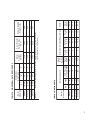
TABLE 1B: RATING DATA
B o i le r
Mo d e l No .
36"
30"
24"
24"
"B"
D i me ns i o ns
S e e F i g ure 1
1 7 .8 4
1 4 .4 6
11 .0 8
7 .7 0
Wa te r
C o nte nt Ga llo ns
3 4 .2 9
2 7 .2 9
2 0 .2 9
1 3 .2 9
He a t Tra ns fe r
S urfa c e A re a S q . F t.
177
145
11 2
64
Wa te r
MB H
I=B =R
NE T
Ra ti ng s
7
7
6
6
Ro und In.
D i a.
8X8
8X8
8X8
8X8
Re c ta ng le
In. x In.
15
15
15
15
He i g ht
F t.
Mi ni mum C hi mne y Re q ui re me nts
8 7 .0
8 7 .0
8 7 .0
8 7 .0
Wa te r
B o i le r
A F UE %
771
658
545
430
A c tua l S hi p p i ng
W e i g ht (L B .)
M a xi m um W o rk i ng P re s s ure : Wa te r : 30 PSI Shipped From Factory (Standard),
40 PSI Optional, 50 PSI Optional
2 2 - 5 /8 "
M P O1 4 7
N O TE : 1 .
1 6 - 5 /8 "
"A"
M P O8 4
B o i le r
M o d e l No .
TABLE 1A: DIMENSIONAL DATA (SEE FIGURE 1)
SECTION I: PRE-INSTALLATION
A. INSPECT SHIPMENT carefully for any signs of
damage.
1. All equipment is carefully manufactured, inspected
and packed. Our responsibility ceases upon delivery
of crated boiler to the carrier in good condition.
2. Any claims for damage or shortage in shipment
must be filed immediately against the carrier by the
consignee. No claims for variances from, or shortage
in orders, will be allowed by the manufacturer
unless presented within sixty (60) days after receipt
of goods.
•
36" for flueway cleaning (MPO231)
b. Clearance from Jacket Left Side Panel • 19" for burner swing door, if opened fully
with burner mounted, otherwise 1" with
burner removed
•
12" access clearance to service rear of
boiler if right side clearance is less
than 12"
•
1" minimum if right side clearance is 12" or
larger to access and service rear of boiler.
B. LOCATE BOILER in front of final position before
removing crate. See Figure 1.
c. Clearance from Jacket Right Side Panel • 3" minimum if left side clearance is 12" or
larger to access and service rear of boiler.
1. LOCATE so that vent pipe connection to chimney
will be short and direct.
d. Clearance from Jacket Rear Panel • 12" minimum for rear smokebox cleaning
2. BOILER IS SUITABLE FOR INSTALLATION
ON COMBUSTIBLE FLOOR. Boiler cannot be
installed on carpeting.
3. FOR BASEMENT INSTALLATION, provide
a solid elevated base, such as concrete, if floor is
not level, or if water may be encountered on floor
around boiler.
4. PROVIDE RECOMMENDED SERVICE
CLEARANCE, if applicable, as follows:
a. Clearance from Jacket Front Panel • 24" for servicing burner
• 24" for flueway cleaning (MPO84 & 147)
• 30" for flueway cleaning (MPO189)
(Note: This dimension will also be
controlled by horizontal to vertical to
horizontal smokepipe arrangement - See
Figures 2 and 16.)
5. For minimum clearances to combustible materials.
See Figure 2.
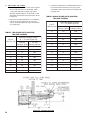
NOTICE
C le a r a n c e t o v e n t in g is fo r s in g le w a ll v e n t
p i p e . I f Ty p e L v e n t i s u s e d , c l e a r a n c e m a y
b e r e d u c e d t o t h e m in im u m r e q u ir e d b y t h e
v e n t p ip e m a n u fa c tu r e r.
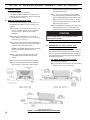
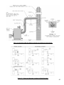
Figure 2: Minimum Installation Clearances To Combustible Materials (Inches)
NOTES:
1. Listed clearances comply with American National Standard
ANSI/NFPA 31, Installation of Oil Burning Equipment.
8
2. MPO boilers can be installed in rooms with clearances from
combustible material as listed above. Listed clearances cannot
be reduced for alcove or closet installations.
3. For reduced clearances to combustible material, protection
must be provided as described in the above ANSI/NFPA 31
standard.
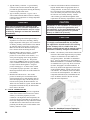
C. PROVIDE COMBUSTION AND VENTILATION
AIR. Local and National Codes may apply and should
be referenced.
WARNING
Ad e q u a t e c o m b u s t i o n a n d v e n t i l a t i o n
a ir m u s t b e p r o v id e d t o a s s u r e p r o p e r
c o m b u s t io n a n d t o m a in t a in s a fe
a m b ie n t a ir t e m p e r a t u r e s .
D o n o t in s t a ll b o ile r w h e r e g a s o lin e o r
o t h e r fla m m a b le v a p o r s o r liq u id s , o r
s o u r c e s o f h y d r o c a r b o n s ( i.e . b le a c h e s ,
fa b r ic s o ft e n e r s , e t c .) a r e u s e d o r
s to re d .
1. Determine volume of space (boiler room). Rooms
communicating directly with the space in which
the appliances are installed, through openings not
furnished with doors, are considered a part of the
space.
Volume(ft3) = Length(ft) x Width(ft) x Height(ft)
2. Determine total input of all appliances in the space.
Add inputs of all appliances in the space and round
the result to the nearest 1000 BTU per hour.
3. Determine type of space. Divide Volume by total
input of all appliances in space. If the result is
greater than or equal to 50 ft3/1000 BTU per hour,
then it is considered an unconfined space. If the
result is less than 50 ft3/1000 BTU per hour then the
space is considered a confined space.
4. For boiler located in an unconfined space of a
conventionally constructed building, the fresh
air infiltration through cracks around windows
and doors normally provides adequate air for
combustion and ventilation.
5. For boiler located in a confined space or an
unconfined space in a building of unusually tight
construction, provide outdoor air.
a. Outdoor air for combustion may be provided
with an optional Burnham MPO (V8) Inlet Air
Accessory Kit, Part Number 611280031 (only
available and suitable for use on Beckett AFG
with burner enclosure cover burner). See
Section V for installation details.
or
b. Outdoor air may be provided with the use of two
permanent openings which communicate directly
or by duct with the outdoors or spaces (crawl or
attic) freely communicating with the outdoors.
Locate one opening within 12 inches of top
of space. Locate remaining opening within 12
inches of bottom of space. Minimum dimension
of air opening is 3 inches. Size each opening per
following:
i. Direct communication with outdoors.
Minimum free area of 1 square inch per
4,000 BTU per hour input of all equipment
in space.
ii. Vertical ducts. Minimum free area of 1
square inch per 4,000 BTU per hour input of
all equipment in space. Duct cross-sectional
area shall be same as opening free area.
iii. Horizontal ducts. Minimum free area of 1
square inch per 2,000 BTU per hour input of
all equipment in space. Duct cross-sectional
area shall be same as opening free area.
Alternate method for boiler located within
confined space. Use indoor air if two
permanent openings communicate directly
with additional space(s) of sufficient volume
such that combined volume of all spaces
meet criteria for unconfined space. Size each
opening for minimum free area of 1 square
inch per 1,000 BTU per hour input of all
equipment in spaces, but not less than 100
square inches.
6. Louvers and Grilles of Ventilation Ducts
a. All outside openings should be screened and
louvered. Screens used should not be smaller
than 1/4 inch mesh. Louvers will prevent the
entrance of rain and snow.
b. Free area requirements need to consider the
blocking effect of louvers, grilles, or screens
protecting the openings. If the free area of the
louver or grille is not known, assume wood
louvers have 20-25 percent free area and metal
louvers and grilles have 60-75 percent free area.
c. Louvers and grilles must be fixed in the open
position, or interlocked with the equipment to
open automatically during equipment operation.
9
SECTION II: PACKAGED BOILER ASSEMBLY - TRIM & CONTROLS
A. REMOVE CRATE.
1. Remove all fasteners at crate skid.
2. Lift outside container and remove all other inside
protective spacers and bracing. Remove burner and
miscellaneous parts cartons.
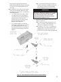
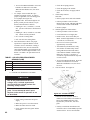
B. REMOVE BOILER FROM SKID.
1. To reduce the risk of damage to boiler jacket, use
the following procedure to remove from skid, see
Figure 3:
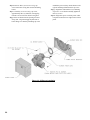
Step 1. Boiler is secured to base with (4) 5/16" cap
screws, (2) in front and (2) in rear of shipping
skid, see Figure 3. Remove all securing
hardware.
Step 2. Place wooden block(s) 12" from rear of
skid as shown (one piece 4" x 4" x 16" lg. or two
pieces of 2" x 4" x 16" lg.)
Step 3. Insert 1" Sch. 40 pipe handles through leg
hole in front and rear legs. Center end of pipe on
wooden blocks as shown in Figure 3.
NOTE: Pipe handles should extend a minimum
of 48" beyond jacket front panel for best
leverage.
Step 4. Using the pipe handles, lift boiler until
adjustable legs are elevated above the deck
boards.
Step 5. Remove skid from underneath the boiler.
Step 6. Lower pipe handles until front adjustable
legs touch floor. If necessary, place wooden
blocks under front legs before lowering to
provide hand clearance.
Step 7. To lower rear of boiler, tilt unit slightly
forward by pushing on smokebox collar or lift
pipes protruding through rear legs until wooden
blocks can be removed (see Figure 3). Slowly
allow the weight of the boiler to tilt backward
until rear legs rest on floor.
Step 8. If wood block was placed under front legs,
lift pipe handles, remove wooden block and
lower front legs to floor. Remove pipe handles.
CAUTION
D o n o t d r o p b o ile r. D o n o t b u m p b o ile r
ja c k e t a g a in s t flo o r.
C. MOVE BOILER TO PERMANENT POSITION
by sliding or walking.
D. PROCEDURE TO OPEN, CLOSE AND
SECURE BURNER SWING DOOR
Throughout this manual you will be instructed to open
and close the burner swing door for various reasons.
There is a proper and improper method to closing and
securing the burner swing door opened for inspection,
cleaning or field service.
1. TO OPEN BURNER SWING DOOR
(see Figures 4A and 4B).
Step 1. Loosen but do not remove left side latching
hardware (3/8" x 1-3/4" lg. tap bolt).
Figure 3: Packaged Boiler Removal from Skid
10
Figure 4A: Partial Front View - Burner Swing Door Mounted to Boiler - Fully Closed and Secured
Step 2. Loosen and remove right side latching
hardware (5/16" x 1-3/4" lg. tap bolt and
washer).
Step 3. Remove left side latching hardware (5/16" x
1-3/4" lg. tap bolt and washer).
Step 4. Disconnect burner power cord from
receptacle located in lower right corner of jacket
front panel.
Step 5. Door can be swung to the fully open
position, approximately 90° to 120°, with the
burner mounted providing that there is 19" of
clearance to the adjacent wall, see Figure 1.
NOTE: If reduced clearance prevents the door
from opening fully, one of the following can
provide full access:
a. Burner can be removed to allow full rotation
of door.
b. Door with burner mounted can be lifted
off mounting bracket and set aside during
servicing.
c. The door mounting hardware is reversible
from left side hinge (as shipped) to right side
hinge.
To reverse hinge arrangement (see Figure
4A):
• Lift door off mounting bracket and set
aside.
• Remove mounting bracket and hardware
from left side.
• Remove upper jacket front panel retaining
screw (5/16" x 1/2" lg. Phillip Pan head
machine screw) from right side of door
and re-install in vacated upper mounting
bracket tapping. Do not tighten.
• Move lower jacket panel retaining screw
from right side to left tapping. Do not
tighten.
• Rotate door mounting bracket 180°.
Insert 5/16" cap screw through top hole in
bracket and install in upper vacated jacket
hole on right side of door.
• Install second 5/16" cap through bracket
hole into lower vacated tapping on right
side.
• Tighten both sets of hardware to secure
jacket and mounting bracket.
• Lift door and place integral cast hinge
pins on door into slotted mounting bracket
holes.
2. Perform routine inspection, service or cleaning as
necessary.
3. To close Burner Swing Door (see Figures 4A and
4B):
Step 1. From the fully open position, rotate Burner
Swing Door to the closed position.
Step 2. If necessary, place your right hand under
the burner air tube to lift upward. Lift the
door up unto the built-in cast ramp/door rest
11
Figure 4B: Top View - Burner Swing Door Mounted to Cast Iron Block Assembly (Jacket Removed for Clarity)
12
(protruding from the bottom of the front section
casting - see Figure 4A).
E. INSPECT SWING DOOR INSULATION AND
ROPE GASKET.
Step 3. Use one hand to help hold door in position
by lifting up on rear burner housing or applying
pressure directly to the door while re-installing
the securing hardware with your opposite hand.
Always install right side latching hardware
(5/16" x 1-3/4" lg. tap bolt and flat washer)
first, then install left side hinge hardware (5/16"
x 1-3/4" lg. tap bolt and flat washer) second.
Apply additional pressure while hand tightening
the hardware as far as possible, then release the
pressure.
1. Open burner swing door using procedure previously
outlined in Paragraph D of this section.
2. Inspect fiberglass rope located on the swing door.
The rope must be evenly distributed around the
perimeter of the door groove and cannot bunch or
overhang. There must not be a gap where the two
ends of the rope meet. Repair or replace if the rope
is damaged or if there is a gap between the ends.
3. Inspect burner swing door insulation for damage and
proper type.
a. By design, cast bars on front section between
the combustion chamber and between the left
and right side 2nd and 3rd pass flueway should
make an impression in door insulation to seal the
chambers.
NOTICE
W h e n s e c u r in g b u r n e r s w in g d o o r m a k e
s u r e d o o r is d r a w n - in e q u a lly o n b o t h s id e s .
Step 4. Use a hand wrench to tighten door hardware
and always start with the right side cap
screw first. Use an alternating tightening
method from right side tap bolt to left side tap
bolt to tighten door equally until sealed without
applying excessive torque. Never tighten left
side flange bolt first or tighten either piece of
hardware 100% without using the alternating
tightening method described above.
Failure to follow the prescribed procedure could
cause thread damage to casting or a leak in the
door seal. If left side tap bolt is tightened before
right side tap bolt, right side of door can not be
drawn-in to provide an air tight seal, as shown in
Figure 4C. Applying excessive torque will only
cause thread damage.
b. By design, door insulation on model MPO231
will have two (2) by-pass pockets cast into
the insulation centered on the bar between the
combustion chamber and 3rd pass flueways.
On models MPO84 thru MPO189 these pockets
should not be present. If insulation is damaged
or not of proper type regarding pockets, it must
be replaced.
4. Do not close and secure door at this time, proceed to
Field Assembly Details, Paragraph F.
F.
FIELD ASSEMBLY OF BOILER TRIM AND
CONTROLS
Open miscellaneous parts carton and remove contents.
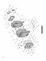
Identify the components using the illustrations (Figures
Figure 4C: Top View - Burner Swing Door Fully Closed but Not Properly Secured or Sealed
13
5 thru 12) throughout the assembly sequence outlined
below as it applies to your installation.
1. Install supply manifold and aquastat control, refer to
Figure 5.
Step a. Remove two (2) #8 x 1/2" lg. sheet metal
screws securing jacket top rear panel to jacket
rear panel. Slightly lift and pull jacket top rear
panel away from jacket top panel to gain access
to internal J-box wiring harness.
Step b. Locate the cast iron supply manifold shown
in Figure 5. Apply thread sealant to 1-1/2" NPT
male threads. Thread male end into 1-1/2" NPT
top tapping on rear section. Using hex head on
top, tighten manifold until 1/2" NPT boss for
control well is facing forward and joint is water
tight.
Step c. Locate 1/2" NPT x 1-1/2" immersion well.
Apply thread sealant to 1/2" NPT male threads.
Thread well into 1/2" NPT boss on front of
supply manifold. Using hex head, tighten well
until water tight.
Step d. Locate L7248C Aquastat Control/Harness
Assembly. Loosen mounting screw on bottom of
case. Insert sensor into immersion well. Mount
control on immersion well and tighten screw to
secure control in horizontal position with harness
on right side as shown in Figure 5.
Step e. Insert two (2) brown thermostat wires and
three (3) aquastat wires with Molex socket
connector located on opposite end of aquastat
harness through 7/8" dia. blank knockout in
jacket top panel. Fish these wires to rear of
internal junction box. Insert snap-in conduit
connector in 7/8" blank knockout, squeeze tabs
on side of connector, push into knockout and
release tabs to lock connector in place.
Step f. Inside internal junction box, locate wires
with mating aquastat plug connector labeled
"Aquastat" (refer to Figure 6 for details of
harness located inside internal junction box).
Align mating halves of socket connector from
aquastat control with harness plug connector.
Push connectors together until snap on connector
is locked in place.
2. If required on this water boiler application, install
low water cut-off (LWCO) Kit, optional equipment
- Burnham P/N 100106-01, refer to Figure 7. Also
refer to instructions provided with LWCO Kit.
If not required, proceed to Paragraph 3.
Step a. Apply sealant to probe threads and install
in 3/4" NPT tapping on right side of manifold as
shown. Tighten so that the mounting screws are
horizontally aligned and joint is water tight.
Step b. Remove wing nut from the probe terminal.
Loosen screw and open cover on control box.
Figure 5: Supply Manifold and Aquastat Control Assembly Details
14
Figure 6: Internal Junction Box and Wiring Harness Details
Mount the control box on the probe by aligning
the keyhole slots with the probe mounting
screws. Replace the wing nut. Secure the
control box by tightening wing nut and two (2)
mounting screws.
Step c. Remove snap-in plug from 7/8" dia. center
knockout, adjacent to aquastat control harness.
Step d. Insert three (3) wires with Molex connector
located on opposite end of LWCO harness
through 7/8" dia. knockout. Fish wires with
Molex connector to rear of internal junction box.
Insert snap-in conduit connector into 7/8" dia.
knockout, squeeze tabs on side of connector,
push into knockout and release tabs to lock
connector in place.
Step e. Inside internal junction box, locate wires
with mating LWCO socket connector labeled
"LWCO" (refer to Figure 6 for details of harness
located inside internal junction box). Remove
the factory installed socket plug jumper from
LWCO harness socket connector and discard.
Align mating halves of plug connector from
LWCO control with harness socket connector.
Push connectors together until snap on side of
connector is locked in place.
3. If required on this water boiler application,
install Auxiliary Dual Limit Control Kit, optional
equipment - Burnham P/N 100107-01, refer to
Figure 8. Also refer to instructions provided with
Auxiliary Dual Limit Control Kit.
If not required, proceed to Paragraph 4.
Step a. Locate 1/2" NPT x 1-1/2 immersion well.
Apply thread sealant to 1/2" NPT male threads.
Thread well into 1/2" NPT boss on left side of
supply manifold. Using hex head, tighten well
until water tight.
Step b. Locate L4080B Auxiliary Limit Control/
Harness Assembly. Loosen mounting screw on
side of case. Insert sensing bulb into immersion
well. Mount control on immersion well and
tighten screw to secure control in vertical
position with harness extending toward rear as
shown in Figure 8.
Step c. Remove snap-in plug from 7/8" dia.
knockout closest to supply manifold. Remove
locking ring from 90° conduit connector on end
of control harness.
Step d. Insert two (2) wires with Molex connector
located on end of auxiliary limit control harness
through 7/8" dia. knockout. Fish wires with
Molex connector to rear of internal junction
box. Insert 90° conduit connector into 7/8" dia.
knockout, secure to top panel with locking ring.
Step e. Inside internal junction box, locate wires
with mating auxiliary limit socket connector
labeled "Aux. Limit" (refer to Figure 6 for
details of harness located inside internal junction
box). Remove the factory installed socket plug
jumper from harness socket connector and
discard. Align mating halves of plug connector
15
Figure 7: Optional Equipment - Low Water Cut-Off (LWCO) Control Assembly Details
Figure 8: Optional Equipment - Auxiliary Limit Control Assembly Details
from auxiliary limit control with harness socket
connector. Push connectors together until snap,
on side of connector, is locked in place.
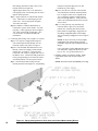
4. Install return manifold and relief valve, refer to
Figure 9.
Step a. Locate the cast iron return manifold with
injector nipple (installed). Apply thread sealant
to 2" NPT male threads. Insert injector nipple
16
into 2" NPT upper rear tapping on rear section,
engage 2" NPT male threads on end of manifold
and hand tighten.
Note: Based on system return piping and access
to service boiler, see Figure 1 and Figures 13A
and 13B, predetermine if manifold orientation
is to be positioned for vertical, horizontal left or
horizontal right side return piping as shown in
Figure 9.
Place a wrench on the hex nut portion and
tighten manifold until the return pipe orientation
is correct for your installation and the joint is
water tight.
Step b. Install relief valve using 3/4" NPT tapping
on side of return manifold. Relief valve must
be installed in vertical position. If orientation of
return manifold is for:
• 1-1/2" NPT vertical return piping - Install
3/4" NPT x 90° street ell (not furnished)
into either the left or right side tapping on
return manifold. Install relief valve
vertically into street ell. Install 3/4" pipe
plug (not furnished) in tapping on
opposite side (see Figure 9).
•
1-1/2" NPT horizontal left or right side
return piping - Install relief valve vertically
in 3/4" NPT tapping located on top of
return manifold. Install 3/4" pipe plug (not
furnished) in bottom tapping as shown (see
Figure 9).
Step c. Pipe discharge of relief valve as shown in
Figures 13A and 13B. Installation of the relief
valve must be consistent with ANSI/ASME
Boiler and Pressure Vessel Code, Section IV.
WARNING
R e lie f v a lv e d is c h a r g e p ip in g m u s t b e p ip e d
n e a r flo o r t o e lim in a t e p o t e n t ia l o f s e v e r e
b u r n s . D o n o t p ip e in a n y a r e a w h e r e
fr e e z in g c o u ld o c c u r. D o n o t in s ta ll a n y
s h u t - o ff v a lv e s , p lu g s o r c a p s .
5. Install drain valve and indirect water heater return
piping, see Figure 10.
Step a. Apply pipe sealant to both ends of 1-1/4"
NPT x 5" lg. nipple. Thread nipple into 1-1/4"
NPT lower rear tapping on rear section.
Step b. Thread 1-1/4" x 1-1/4" x 3/4" NPT tee on
opposite end of 5" lg. nipple installed in Step a.
NOTE: Based on access for servicing and
location of sewer or floor drain, when tightening
Figure 9: Return Manifold and Relief Valve Assembly Details
17
these fittings, determine if drain valve is to be
located on the left or right side.
Tighten nipple and tee into 1-1/4" NPT lower
rear tapping on rear section until joints are water
tight for desired position.
Step c. Apply sealant to 3/4" NPT thread on drain
valve. Thread into 3/4" NPT tapping on side
outlet of tee. Use hex nut portion to tighten
valve until water tight.
Step d. If Alliance ™ Indirect Water Heater is
connected to system, do not install 1-1/4" NPT
pipe plug. Connect piping as shown in Figures
13A, 13B, 15A and 15B, as applicable. Also
refer to Alliance ™ manual for additional
information.
6. Connecting field wiring, refer to Figures 5, 6 and 19.
Step a. 120 volt power supply field wiring will
enter internal junction box through 7/8" dia.
knockout in jacket rear panel, see Figure 5.
Step b. Locate the black and white harness wires
labeled "120V Power Supply" inside internal
junction box, see Figure 6. Using wire nuts,
connect the 120 volt power supply field wires to
the harness wires. Connect the field ground wire
to the green grounding screw located in bottom
of internal junction, refer to Figures 6 and 20.
Step c. 24V thermostat field wiring will enter
internal junction box through 5/16" snap bushing
located on rear panel adjacent to 7/8" dia.
knockout for power supply.
Step d. Locate the two (2) brown wires labeled
"24V Thermostat" inside the internal junction
box, see Figure 6 (these wires originate from
"T-T" terminals in aquastat control and feed
into J-box through harness). Using wire nuts,
connect 24 volt field thermostat wires to brown
wires in J-box.
Step e. Locate jacket top rear panel that was
removed earlier to gain access to internal
junction box. Position panel between side
panels, hold on a slight angle, engage tabs on
front flange of top rear panel with rectangle
slots on rear flange of top panel, refer to Figures
5 and 9.
NOTE: It may be necessary to lift up slightly
on top panel near slotted opening at supply
manifold to align tabs with rectangular slots on
flanges.
Lower rear flange of jacket top rear panel down
over rear panel. Align holes and secure with
two (2) #8 x 1/2" lg. sheet metal screws.
7. Installing stainless steel flueway baffles. Baffle
requirements differ from model to model, see
Table 2.
NOTE: Read caution statement before proceeding.
Figure 10: Piping Arrangement for Drain Valve and Indirect Water Heating Return
18
CAUTION
T h e s e b a ffle s w ill g e n e r a t e h ig h e r
e ffic ie n c ie s a n d lo w e r s t a c k t e m p e r a t u r e s .
U n d e r c e r t a in c o n d it io n s , a lo w e r g r o s s
s t a c k t e m p e r a t u r e e n t e r in g t h e c h im n e y h a s
t h e p o t e n t ia l t o b e c o o le d b e lo w t h e d e w
p o in t a n d c r e a t e c o n d e n s a t e o n in t e r io r
s u r fa c e s . F lu e g a s c o n d e n s a t e is c o r r o s iv e ,
w h ic h r e q u ir e s s p e c ia l c o n s id e r a t io n a n d
m u s t b e a d d r e s s e d im m e d ia te ly.
D O N OT in s t a ll b a ffle s u n t il y o u h a v e r e a d
S e c tio n V, " Ve n tin g " c o m p le te ly.
TABLE 2: BAFFLE USAGE
B o i le r
Mo d e l
M P O8 4
B a ffle Us a g e
2 nd P a s s
3 rd P a s s
No ne
(2 )
P /N 1 0 0 0 8 1 - 0 1
(2 )
P /N 1 0 0 0 4 2 - 0 1
No ne
8. Close the burner swing door and securely seal the
door to the boiler front section by reinstalling the
hardware and securing the door using procedure
previously outlined in Paragraph D of this section.
NOTICE
W h e n s e c u r in g b u r n e r s w in g d o o r m a k e
s u r e d o o r is d r a w n - in e q u a lly o n b o t h s id e s .
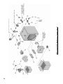
9. Install oil burner, refer to Figure 12.
Step a. Open burner carton and remove contents.
Step b. Check oil nozzle in burner for size, angle
and type, inspect electrode settings, check head
setting, check air band and air shutter settings,
refer to Table 6 at rear of this manual.
Step c. Place oil burner gasket on burner and align
holes.
CAUTION
D o n o t in s t a ll b u r n e r w it h o u t g a s k e t .
M P O1 4 7
M P O1 8 9
M P O2 3 1
Step a. Install stainless steel baffles provided in
miscellaneous parts carton as follows, refer to
Table 2 and Figure 11:
•
Model MPO84 - To install flueway baffle
in 3rd pass on left side of boiler, hold baffle
with word "Left" readable at the top. Slide
baffle in flueway until position tab touches
fins on left side of 3rd pass flueway. To
install flueway baffle in 3rd pass flueway on
right side of boiler, hold baffle with word
"Right" readable at the top. Slide baffle in
flueway until position tab touches fins on
right side of 3rd pass flueway.
•
Models MPO147, MPO189 and MPO231
- To install flueway baffle in 2nd pass flueway
on left side of boiler, hold baffle with word
"Left" readable at the top. Slide baffle in
flueway until position tab touches fins on
right side of 2nd pass flueway. To install
flueway baffle in 2nd pass flueway on right
side of boier, hold baffle with word "Right"
readable at the top. Slide baffle in flueway
until position tab touches fins on left side of
2nd pass flueway.
NOTE: 2nd and 3rd pass flueway baffle are not
interchangable.
Figure 11: Baffle Orientation in Flueways
19
Step d. Remove three (3) 5/16-18 x 3/4 lg. cap
screw from burner swing door used for mounting
burner.
Step e. Thread (1) 5/16-18 x 3/4 lg. cap screw,
approximately three (3) full turns, into tapping
located at 12:00 o'clock on burner swing door.
Step f. Insert oil burner into the opening of burner
swing door. Align and engage keyhole slot in
burner flange over head of protruding cap screw
installed in previous Step. Rotate burner to the
right to lock flange behind head of cap screw.
Step g. Align holes and install two (2) remaining
cap screws. Level burner and fully tighten all
three (3) screws.
Step h. Plug burner power cord into power outlet
receptacle located in lower right corner of front
panel.
Figure 12: Oil Burner Installation
20
SECTION III: WATER BOILER PIPING
NOTICE
F a ilu r e t o p ip e b o ile r a s s p e c ifie d in t h is m a n u a l m a y r e s u lt in e x c e s s iv e s y s t e m n o is e .
A. EVALUATE THE EXISTING WATER
SYSTEM.
Design a piping system and install boiler which will
prevent oxygen contamination of boiler water and
frequent water additions.
1. There are many possible causes of oxygen
contamination such as:
a. Addition of excessive make-up water as a result
of system leaks.
b. Absorption through open tanks and fittings.
c. Oxygen permeable materials in the distribution
system.
2. In order to insure long product life, oxygen sources
must be eliminated. This can be accomplished by
taking the following measures:
a. Repairing system leaks to eliminate the need for
addition of make-up water.
b. Eliminating open tanks from the system.
c. Eliminating and/or repairing fittings which allow
oxygen absorption.
d. Use of non-permeable materials in the
distribution system.
e. Isolating the boiler from the system water by
installing a heat exchanger.
WAR N IN G
S y s t e m s u p p ly a n d r e t u r n p ip in g m u s t b e
c o n n e c t e d t o c o r r e c t b o ile r m a n if o ld s .
B u r n h a m r e c o m m e n d s s iz in g t h e
s y s t e m c ir c u la t o r t o s u p p ly s u ffic ie n t
flo w ( GP M ) t o a llo w a 2 0 °F t e m p e r a t u r e
d iffe r e n t ia l in t h e s y s t e m . W h e n s iz in g
th e s y s te m c ir c u la to r, th e m o s t
r e s t r ic t iv e s in g le z o n e s h o u ld b e u s e d
t o d e t e r m in e m a x im u m p r e s s u r e d r o p .
CAUTION
M a in t a in m in im u m ½ in c h c le a r a n c e fr o m
h o t w a t e r p ip in g t o c o m b u s t ib le m a t e r ia ls .
B. CONNECT SYSTEM SUPPLY AND RETURN
PIPING TO BOILER. See Figures 13A and 13B.
Also, consult I=B=R Installation and Piping Guides.
1. If this boiler is used in connection with refrigeration
systems, the boiler must be installed so that the
chilled medium is piped in parallel with the heating
boiler using appropriate valves to prevent the chilled
medium from entering the boiler. See Figure 14.
Also, consult I=B=R Installation and Piping Guides.
2. If this boiler is connected to heating coils located
in air handling units where they may be exposed
to refrigerated air, the boiler piping must be
equipped with flow control valves to prevent gravity
circulation of boiler water during the operation of
the cooling system.
3. If boiler is used with an Alliance™ Indirect-Fired
Domestic Water Heater, install the Alliance™ as
a separate heating zone. Refer to the Alliance™
Installation, Operating, and Service Instructions for
additional information.
4. Use a boiler bypass if the boiler is to be operated
in a system which has a large volume or excessive
radiation where low boiler water temperatures may
be encountered (i.e. converted gravity circulation
system, etc.) The bypass should be the same size as
the supply and return lines with valves located in
the bypass and return line as illustrated in Figures
13A and 13B in order to regulate water flow for
maintenance of higher boiler water temperature.
WAR N IN G
T h e u s e o f a lo w w a t e r c u t - o ff d e v ic e , w h ile
n o t r e q u ir e d u n le s s r a d ia t io n le v e l is b e lo w
th e b o ile r, is h ig h ly r e c o m m e n d e d .
If a low water cut-off is required, it must be
mounted in the 3/4" supply manifold tapping (see
Figures 7, 13A and 13B) or in the system piping
above the boiler. The minimum safe water level of
a hot water boiler is just above the highest water
containing cavity of the boiler; that is, a hot water
boiler must be full of water to operate safely.
5. If it is required to perform a long term pressure
test of the hydronic system, the boiler should first
be isolated to avoid a pressure loss due to the escape
of air trapped must first be removed from the boiler.
21
22
Figure 13A: Water Boiler Piping for Circulator Zoned Heating System - Supply Side Circulator
23
Figure 13B: Preferred Water Boiler Piping for Zone Valve Zoned Heating System - Supply Side Circulator
To perform a long term pressure test including the
boiler, ALL trapped air must first be removed from
the boiler.
A loss of pressure during such a test, with no visible
water leakage, is an indication that the boiler
contained trapped air.
Figure 14: Recommended Piping for Combination Heating and Cooling (Refrigeration) System
24
SECTION IV: INDIRECT WATER HEATER PIPING
A. CONNECT ALLIANCE™ INDIRECT WATER
HEATER PIPING as shown in Figures 15A and
15B.
Also refer to Figures 13A and 13B.
1. Refer to Alliance™ manual for additional
information.
Figure 15A: Alliance™ Water Heater Piping w/Supply Side Circulator
on Circulator Zoned Heating System
Figure 15B: Alliance™ Water Heater Piping w/Supply Side Circulator on Zone Valve Zoned Heating System
25
SECTION V: VENTING
A. CHIMNEY VENTING
1. Chimney venting is an important part of a safe
and efficient oil fired appliance system. Contact
your local fire and building officials on specific
requirements for restrictions and the installation
of fuel oil burning equipment. In addition,
consult with a professional knowledgeable on
the requirements of NFPA 31 – Standard for the
Installation of Oil-Burning Equipment and NFPA
211 - Standard for Chimneys, Fireplaces, Vents, and
Solid Fuel-Burning Appliances for installations in
the United States. Installations in Canada must be
reviewed with a professional knowledgeable on the
requirements of CSA B139-04 – Installation Code
for Oil-burning Equipment.
2. The safe venting of oil fired boilers is dependant on
many factors. Some of these factors include:
a. sufficient draft during the entire heating season
to allow for the safe discharge of combustion byproducts and;
b. suitable corrosion protection in the event of
condensing flue gases. Only a trained and
qualified contractor may install this product.
3. The MPO can be vented into a fireclay tile-lined
masonry chimney that meets requirements outlined
in Paragraph 4 below. It can also be vented into
a chimney constructed from type L vent or a
factory built chimney that complies with the type
HT requirements of UL 103. The chimney and
vent pipe shall have a sufficient draft at all times,
to assure safe proper operation of the boiler. See
Figure 16 for recommended installation.
WARNING
D o n o t d e - r a t e t h e a p p lia n c e . F a ilu r e t o fir e
t h e u n it a t it ' s d e s ig n e d in p u t m a y c a u s e
e x c e s s iv e c o n d e n s a t io n u p o n t h e in t e r io r
w a lls o f th e c h im n e y. In a d d itio n , th e lo w e r
in p u t m a y n o t c r e a t e e n o u g h d r a ft t o
a d e q u a t e ly e v a c u a t e t h e b y - p r o d u c t s o f
c o m b u s t io n .
4. Chimney Inspection – Prior to the installation of
any new or replacement fuel burning equipment the
chimney shall be inspected by a qualified installer.
The chimney shall be inspected for integrity as
well as for proper draft and condensate control.
Some jurisdictions require the use of a liner when
changing fuel types. Some jurisdictions require
the use of a liner even when the same fuel is used.
At a minimum, the chimney shall be examined
by a qualified person in accordance with the
requirements of Chapter 11 of NFPA 211, Standard
for Chimneys, Fireplaces, Vents, and Solid FuelBurning Appliances.
26
a. Loose Mortar – Loose mortar could be an
indication of a prior history of condensing flue
gases upon the inside walls of the chimney.
Colder climates are more susceptible to this
condition. Under no circumstances shall a
chimney of this condition be used until it meets
the requirements of NFPA 211 or CSA B13904.
b. Unlined Chimney – Under no circumstances
shall a chimney constructed of brick only
be used. Only approved clay liners or listed
chimney lining systems shall be used as specified
in NFPA 31 or CSA B139-04.
c. Abandoned Openings – Openings through the
chimney wall that are no longer used shall
be sealed in accordance to NFPA 211. Often
abandoned openings are improperly sealed and
usually covered by a gypsum wall covering.
d. Clean Chimney – Chimney shall be free of all
loose debris.
5. Draft Regulator – the draft regulator supplied with
the boiler must be used with this appliance. No
other draft regulator shall be used. Refer to Figures
16 and 17.
B. CHIMNEY CONNECTOR
1. A chimney connector (vent pipe) is used to connect
the boiler to the base of the chimney. The chimney
connector should be kept as short as possible. The
horizontal length of the chimney connector shall not
be greater than 10 feet.
NOTE: Secure chimney connector to cast iron
smokebox collar with three (3) #10 x ½" self drilling
hex head TEK screws provided in miscellaneous
parts carton. Locate screws around perimeter of
connector as shown in Figure 16 and approximately
½" in from edge. Use drill with 5/16" hex bit to
drive screws through connector and smokebox
collar.
D AN GE R
T h e c h im n e y a n d c o n n e c t o r s h a ll b e
in s p e c t e d a n n u a lly fo r s ig n s o f d e b r is a n d
c o r r o s io n . L o o s e m o r t a r a t t h e b a s e o f t h e
c h im n e y m a y b e a s ig n o f c o n d e n s a t e
d a m a g e to th e c h im n e y. A c h im n e y
p r o fe s s io n a l s h a ll b e c o n t a c t e d im m e d ia t e ly
t o e x a m in e t h e d a m a g e a n d r e c o m m e n d a
s o lu t io n . L o n g t e r m o p e r a t io n w h ile in t h is
c o n d it io n m a y c a u s e a v e n t in g fa ilu r e a n d
fo r c e flu e g a s e s in t o t h e liv in g s p a c e . If t h e
c h im n e y is t o b e r e - lin e d u s e t h e
r e c o m m e n d a t i o n s i n N F PA 3 1 , A p p e n d i x E
o r C S A B 1 3 9 -0 4 .
Figure 16: Recommended Vent Pipe Arrangement and Chimney Requirements
Figure 17: Proper and Improper Locations of Draft Regulator
27
2. Type B Chimney Connector - a type B chimney
connector can be used to transmit the flue gases
provided flue gas temperature entering the chimney
connector is greater than 310°F.
3. Type L Chimney Connector - a type L vent or
other suitable material shall be used for a chimney
connector if the temperature or exiting temperature
is less than 310°F.
D AN GE R
An y s i g n s o f c o n d e n s a t e s e e p a g e a t t h e
b a s e o f t h e c h im n e y s h a ll b e in s p e c t e d im m e d ia te ly. T h e d is c o lo r a tio n m a y b e a s ig n
o f c h im n e y d a m a g e a n d m u s t b e r e m e d ie d
im m e d ia te ly.
C. DRAFT
1. The natural draft generated through a chimney is
dependent on several factors including, chimney
height, temperature of flue gases, cross section area
of chimney, chimney wall insulation value, dilution
air and total volume of flue gases, to name a few.
Make sure that the boiler has been running for at
least 5 minutes before measuring the draft.
2. Minimum Draft at Breech (Canopy) – The draft
induced by a chimney must create at least a
pressure of 0 (zero) inches water column (“ w.c.)
at the pressure tapping on the canopy mounted
on rear of boiler (see Figure 18). The pressure
at the canopy cannot be positive since this could
create a condition that allows flue gas by-products
to escape from the draft regulator. A negative
pressure reading up to -.03 inches water column
is acceptable for proper operation. (See Table 6,
Burner Specifications at the rear of this manual for
more details)
3. Minimum Overfire Pressure – The overfire
pressure is another piece of information that is
often measured, however this should be done for
observation purposes only! The breech pressure
must be used to qualify the draft condition. See
Table 6 for more details as a guide. Actual draft and
temperature measurements may be different then
those values in the table.
2. NFPA 31 and CSA B139-04 have information to
help the installer make an appropriate choice of
venting materials. In some cases a chimney may
have to be lined to create sufficient draft. In other
cases, the chimney may have to be lined to prevent
the corrosion of a masonry chimney. Consult
with a chimney specialist knowledgeable on the
requirements for chimney requirements in your area.
CAUTION
An y d o u b t o n t h e c o n d i t i o n o f a c h i m n e y o r
it ’s a b ilit y t o p r e v e n t t h e g e n e r a t io n a n d
a c c u m u la t io n o f flu e g a s c o n d e n s a t e , m u s t
b e r e l i n e d a c c o r d i n g t o N F PA 3 1 ( U n i t e d
S ta te s ) o r C S A B 1 3 9 (C a n a d a ).
C AU T ION
U s e t h e c h im n e y v e n t in g t a b le s a s a g u id e .
It is h ig h ly r e c o m m e n d e d t h a t a n y b o r d e r lin e a p p lic a t io n s h o u ld r e s u lt in t h e r e lin in g
o f t h e c h im n e y w it h a s u it a b le lin e r t h a t
c r e a t e s s u f f ic ie n t d r a f t a n d t o p r o t e c t a g a in s t
c o r r o s io n c a u s e d b y f lu e g a s c o n d e n s a t e .
3. Baffles – The efficiency of the boiler is based on the
insertion of flue baffles supplied with your product.
Under no circumstances are other baffles to be
used on this product. The baffles are installed in
the 2nd pass (two inner flueways) on the MPO147,
MPO189 and MPO231. The baffles on the MPO84
are installed in the 3rd pass only. Refer to Section
II, Item F, Paragraph 7 for baffle installation. If
there is any doubt on the application of this boiler
on the intended chimney, consult with your local
code officials. At a minimum, remove the baffles
to increase the stack temperature. See Table 6 for
temperature differential (∆T) with baffles IN and
OUT. In addition, the lower the CO2 level the
higher the stack temperature.
D. STACK TEMPERATURE
1. The temperature of the flue gases has a significant
effect on the amount of draft created in a vertical
chimney as well as the propensity to create
condensate. The higher the stack temperature, the
greater the amount of draft that can be generated. A
lower stack temperature not only reduces the amount
of draft that can be created but it also increases the
possibility that the flue gases could condense in the
chimney connector or stack.
Figure 18: Smokebox Pressure Tapping for
Checking Draft at Breech
28
WARNING
R e m o v e t h e b a ffle s if t h e r e a r e a n y s ig n s o f
c o n d e n s a t io n in t h e c h im n e y o r c h im n e y
c o n n e c to r. C o n s u lt w ith y o u lo c a l c h im n e y
p r o fe s s io n a l fo r r e c o m m e n d a t io n s .
E. MINIMUM CLEARANCES
See Figure 2 for details regarding clearances to
combustibles for the boiler.
F.
OPTIONAL AIR INTAKE PIPING
INSTALLATION - All air for combustion can be
supplied directly to the burner from outdoors providing
that the criteria for chimney, vent connector and
minimum stack temperature outlined in this section
can be maintained. (ONLY AVAILABLE WITH
BECKETT BURNER). See Figure 19.
1. General
a. Use 4" dia., single wall galvanized metal pipe
and fittings available at most heating distributors
for air intake piping. Maximum allowable air
intake length is 50 equivalent feet. Each elbow
is equal to 6 equivalent feet.
WAR N IN G
D o n o t e x c e e d m a x im u m a llo w a b le a ir
in t a k e le n g t h .
b. Start at burner. Work toward air intake terminal.
c. Maintain minimum of 1/4 inch per foot slope in
horizontal run to air intake terminal. Slope down
toward air intake terminal.
d. Seal all joints gas-tight, using silicone caulk or
self-adhesive aluminum tape.
WAR N IN G
2. After determining location, cut a hole in the wall to
accept 4 inch air intake pipe. See Figure 19.
U s in g o u t d o o r a ir in t h e m id d le o f
w in t e r m a y r e s u lt in lo w e r s t a c k
t e m p e r a t u r e s a n d c h im n e y d e g r a d a t io n .
An y s i g n s o f c o n d e n s a t e s e e p a g e o r
d is c o lo r a t io n a t t h e b a s e o f c h im n e y
m u s t b e r e m e d ie d im m e d ia t e ly p e r t h e
d e t a ils o u t lin e d in t h is s e c t io n .
3. Remove the metal knockout in right side of burner
cover. Install Burnham Inlet Air Accessory Kit, Part
Number 611280031.
D o n o t r e d u c e s iz e o f a ir in t a k e p ip e .
R e a d , u n d e r s t a n d a n d fo llo w
c o m b u s t io n a ir in s t r u c t io n r e s t r ic t io n s
c o n t a in e d in t h e P r e - In s t a lla t io n
S e c t io n o f t h is m a n u a l.
4. Mount the Vacuum Relief Valve Tee Assembly (P/N
8116268 included with Kit) or 90° elbow into the
burner inlet ring. See Figure 18.
a. Secure with at least three (3) sheet metal screws
evenly spaced around the burner inlet ring.
b. Assemble the vacuum relief valve balance
weight onto the gate. Refer to the vacuum relief
valve manufacturer's instructions.
Figure 19: Optional Air Intake Piping Installation - Only Available with Beckett Burner
29
c. Mount the vacuum relief valve into the tee and
fasten with a screw and nut in collar tabs. To
ensure proper operation, the gate must be level
across the pivot point and plumb. Refer to
vacuum relief valve manufacturer's instructions.
5. Install remainder of air intake, securing each joint
with at least three (3) sheet metal screws evenly
spaced.
6. Install air intake terminal. See Figure 19.
NOTICE
In t a k e t e r m in a l m u s t b e a t le a s t 1 2 in c h e s
a b o v e g r a d e p lu s s n o w a c c u m u la t io n .
30
7. Seal all external joints with weatherproof caulk.
WAR N IN G
D o n o t lo c a t e a ir in t a k e w h e r e p e t r o le u m
d is t illa t e s , C F C ' s , d e t e r g e n t s , v o la t ile
v a p o r s o r a n y o t h e r c h e m ic a ls a r e p r e s e n t .
S e v e r e b o ile r c o r r o s io n a n d fa ilu r e w ill
r e s u lt .
SECTION VI: ELECTRICAL
D AN G E R
P o s it iv e ly a s s u r e a ll e le c t r ic a l c o n n e c t io n s a r e u n p o w e r e d b e fo r e a t t e m p t in g in s t a lla t io n o r s e r v ic e
o f e le c t r ic a l c o m p o n e n t s o r c o n n e c t io n s o f t h e b o ile r o r b u ild in g . L o c k o u t a ll e le c t r ic a l b o x e s
w it h p a d lo c k o n c e p o w e r is t u r n e d o ff.
WAR N IN G
F a ilu r e t o p r o p e r ly w ir e e le c t r ic a l c o n n e c t io n s t o t h e b o ile r m a y r e s u lt in s e r io u s p h y s ic a l
h a rm.
E le c t r ic a l p o w e r m a y b e fr o m m o r e t h a n o n e s o u r c e . M a k e s u r e a ll p o w e r is o ff b e fo r e
a t t e m p t in g a n y e le c t r ic a l w o r k .
E a c h b o ile r m u s t b e p r o t e c t e d w it h a p r o p e r ly s iz e d fu s e d d is c o n n e c t .
N e v e r ju m p o u t o r m a k e in o p e r a t iv e a n y s a f e t y o r o p e r a t in g c o n t r o ls .
A. GENERAL
1. Install wiring and electrically ground boiler in
accordance with requirements of the authority
having jurisdiction, or in absence of such
requirements the National Electrical Code, ANSI/
NFPA 70, and/or the CSA C22.1 Electric Code.
2. Refer to National Electric Code or Local Electric
Codes for proper size and type of wire required.
Follow Code.
3. A separate electrical circuit must be run from
the main electrical service with an over-current
device/disconnect in the circuit. A service switch is
recommended and may be required by some local
jurisdictions.
4. Use anti-short bushings on all wiring passing
through boiler jacket, junction boxes and/or control
boxes.
5. Use armored cable (BX) over all exposed line
voltage wiring.
6. If an Alliance™ indirect water heater is used, use
priority zoning. Do not use priority zoning for
Hydro-Air Systems.
7. Wiring should conform to Figure 20.
B. INSTALL A ROOM THERMOSTAT on an
inside wall about four feet above floor. Never install
thermostat on an outside wall or where it will be
influenced by drafts, hot or cold water pipes, lighting
fixtures, television, rays of the sun or near a fireplace.
Keep large furniture away from thermostat so there will
be free movement of room air around this control.
Heat Anticipator in Thermostat should be set to match
the requirements of the control to which it is connected.
See Figure 20 for desired system and heat anticipator
setting. If system tends to overheat above the
thermostat's temperature setting, reduce heat anticipator
setting by .1 or .2 amps. If system tends to short cycle
without reaching desired room temperature, increase
heat anticipator setting by .1 or .2 amps.
31
32
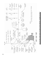
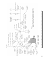
A call for heat by the thermostat energizes the L7248C control which in turn energizes the primary control to turn on the burner. The burner will operate in the following sequence:
Prepurge for the first 10 seconds; fire until the thermostat is satisfied or the limit setting on the operating (high) limit is reached; post-purge for the last 10 seconds. The circulator will
operate as long as the thermostat is calling for heat. If the thermostat is not satisfied and the operating (high) limit is reached, the circulator will continue to operate, and the burner will stop
until the operating (high) limit is closed by a 15°F drop in boiler water temperature.
On water boiler equipped with Optional L4080B Auxiliary High Limit Control, if boiler water temperature exceeds the operating limit setting and reaches the high limit setting, the circulator
will continue to operate, and the burner will stop until the high limit is closed by an 8°F drop in boiler water temperature.
On burner start, if the cad cell does not see flame within approximately 15 seconds, primary control will shut burner down and enter into a recycle mode, after 60 seconds burner will restart
and repeat trial for ignition. If after three (3) trials for ignition, flame is not detected, control will enter into restricted mode and must be reset manually before burner can be restarted.
On water boiler equipped with optional low water cut-off (LWCO) control, if probe senses a low water condition, power to the L7248C control is de-energized. When water level is
replenished, LWCO will automatically re-energize sending power to the L7248C control.
BOILER SEQUENCE OF OPERATION
Figure 20: Schematic Wiring Diagram, Standard Control Set w/Optional LWCO and/or High Limit Accessory Kit
SECTION VII: OIL PIPING
A. GENERAL
WAR N IN G
1. Use flexible oil line(s) so the burner swing door
can be opened without disconnecting the oil supply
piping.
2. A supply line fuel oil filter is recommended as a
minimum for all firing rates but a pleated paper fuel
oil filter is recommended for the firing rates below
1.0 gph to prevent nozzle fouling.
3. Use Flared fittings only. Cast iron fittings cannot be
used.
N OT IC E
U n d e r n o c ir c u m s t a n c e s c a n c o p p e r w it h
s w e a t s t y le c o n n e c t o r s b e u s e d .
NOTICE
S o m e ju r is d ic t io n s r e q u ir e t h e u s e o f a
f u s ib le s h u t o f f v a lv e a t t h e t a n k a n d /o r t h e
b u r n e r. In a d d itio n , s o m e ju r is d ic tio n s
r e q u ir e t h e u s e o f a fu s ib le e le c t r ic a l
in t e r lo c k w it h t h e b u r n e r c ir c u it . C h e c k
y o u r lo c a l C o d e s fo r s p e c ia l r e q u ir e m e n t s .
B. SINGLE PIPE OIL LINES
D o n o t u s e c o m p r e s s io n f it t in g s .
Oil p ip in g m u s t b e a b s o lu t e ly a ir t ig h t o r
le a k s o r lo s s o f p r im e m a y r e s u lt . B le e d
lin e a n d fu e l u n it c o mp le te ly.
R e f e r t o y o u r lo c a l j u r i s d i c t i o n s r e g a r d in g a n y s p e c ia l c o n s id e r a t io n s f o r f u e l
s u p p ly r e q u ir e m e n t s . In a d d i t io n , r e f e r t o
N F PA 3 1 , S ta n d a rd fo r th e In s ta lla tio n o f
Oil- B u r n in g E q u ip m e n t f o r In s t a lla t io n s in
t h e U n it e d S t a t e s a n d C S A B 1 3 9 - 0 4 f o r
In s t a lla t io n in C a n a d a .
4. Use of a high efficiency micron filter (Garber or
equivalent) in addition to a conventional filter is
highly recommended.
5. Piping used to connect the oil burner to the oil
supply tank shall not be smaller than 3/8" iron pipe
or 3/8" OD copper tubing. Copper tubing shall have
a .032" minimum wall thickness.
1. Standard burners are provided with single-stage
3450 rpm fuel units with the bypass plug removed
for single-pipe installations.
2. The single-stage fuel unit may be installed singlepipe with gravity feed or lift. Maximum allowable
lift is 8 feet. See Figure 21.
3. Fuel Oil Line Deaerator – On many occasions a
leaky oil delivery line can introduce air into the
fuel oil supply system. This often creates a rough
starting condition and can create a burner lockout
state. In addition to fixing the leak, a fuel line
deaerator can be installed to eliminate air. The
single line from the fuel tank is connected to the
deaerator. The burner pump must be connected
to the deaerator as a two pipe system. Follow the
oil pump manufacturer’s recommendations for
conversion to a two pipe system.
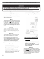
Figure 21: Single Pipe Oil Line
33
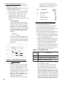
C. TWO PIPE OIL LINES
1. For two piped systems, where more lift is required,
the two-stage fuel unit is recommended. Table
3 (two-stage) and Table 4 (single-stage) show
allowable lift and lengths of 3/8 inch and 1/2 inch
OD tubing for both suction and return lines. Refer
to Figure 22.
2. Follow the oil pump manufacturer’s recommendations on the proper connections for a two pipe
system. Some manufacturers require the insertion
of a bypass plug.
TABLE 3: TWO-STAGE UNITS (3450 RPM) TWO PIPE SYSTEMS
L i ft " H"
(S e e F i g . 2 5 )
Ma xi mum L e ng th o f Tub i ng
" H" + " R" (S e e F i g ure 2 5 )
3. Under no circumstances is a manual shutoff valve to
be located on the return line of a two pipe system.
Accidental closure of the return line will rupture the
oil pump seals.
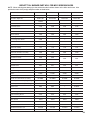
TABLE 4: SINGLE-STAGE UNITS (3450 RPM) TWO PIPE SYSTEMS
L i ft " H"
(S e e F i g . 2 5 )
3 /8 " O D
Tub i ng (3 GP H)
1 /2 " O D
Tub i ng (3 GP H)
0'
84'
100'
1'
78'
100'
2'
73'
100'
3'
68'
100'
3 /8 " O D
Tub i ng (3 GP H)
1 /2 " O D
Tub i ng (3 GP H)
4'
63'
100'
5'
57'
100'
0'
93'
100'
6'
52'
100'
2'
85'
100'
7'
47'
100'
4'
77'
100'
8'
42'
100'
6'
69'
100'
9'
36'
100'
8'
60'
100'
10'
31'
100'
10'
52'
100'
11 '
26'
100'
12'
44'
100'
12'
21'
83'
14'
36'
100'
13'
---
62'
16'
27'
100'
14'
---
41'
18'
---
76'
Figure 22: Two Pipe Oil Lines
34
Ma xi mum L e ng th o f Tub i ng
" H" + " R" (S e e F i g ure 2 5 )
SECTION VIII: SYSTEM START-UP
WAR N IN G
Al l b o i l e r s e q u i p p e d w i t h b u r n e r s w i n g d o o r h a v e a p o t e n t i a l h a z a r d w h i c h c a n c a u s e s e v e r e
p r o p e r ty d a m a g e , p e r s o n a l in ju r y o r lo s s o f life if ig n o r e d . B e fo r e o p e n in g s w in g d o o r, tu r n o ff
s e r v ic e s w itc h to b o ile r to p r e v e n t a c c id e n ta l fir in g o f b u r n e r o u ts id e th e c o m b u s tio n c h a m b e r.
B e s u r e t o t ig h t e n s w in g d o o r fa s t e n e r c o m p le t e ly w h e n s e r v ic e is c o m p le t e d . In a d d it io n , t h e
b u r n e r p o w e r c o r d w ill h a v e t o b e d is c o n n e c t e d f r o m t h e r e c e p t a c le in t h e f r o n t ja c k e t .
A. ALWAYS INSPECT INSTALLATION
BEFORE STARTING BURNER.
1. Verify that the venting, water piping, oil piping, and
electrical system are installed properly. Refer to
Installation Instructions contained in this manual.
2. Confirm all electrical, water and oil supplies are
turned off at the source and that the vent is clear
from obstructions.
WAR N IN G
C o m p le t e ly r e a d , u n d e r s t a n d a n d fo llo w a ll
in s t r u c t io n s in t h is m a n u a l b e fo r e
a t t e m p t in g s t a r t u p .
B. FILL HEATING SYSTEM WITH WATER.
N OT IC E
It is im p o r t a n t t o p r o p e r ly r e m o v e t h e o il
a n d d ir t fr o m t h e s y s t e m . F a ilu r e t o c le a n
t h e s y s t e m c a n r e s u lt in c lo g g e d a ir v e n t s ,
c ir c u la t o r d a m a g e a n d s e iz e d z o n e v a lv e s .
CLEAN HEATING SYSTEM if boiler water is
dirty.
Refer to Maintenance and Service Instructions Section
of this manual for proper cleaning instructions for water
boilers.
1. HOT WATER BOILERS. Fill entire heating
system with water and vent air from system. Use
the following procedure on a series loop or multizoned system installed as per Figures 13A and 13B,
to remove air from system when filling:
a. Close full port ball valve in boiler system piping.
b. Isolate all zones by closing zone valves or shutoff valves in supply and return of each zone(s).
c. Attach a hose to vertical purge valve in boiler
system supply piping up stream from the full
port ball valve.
(Note - Terminate hose in five gallon bucket at a
suitable floor drain or outdoor area).
d. Starting with one zone at a time, open zone valve
or shut-off valve in boiler supply and return
piping.
e. Open purge valve.
f. Open shut-off valve in cold water supply piping
located between the air scoop and expansion
tank.
g. Allow water to overflow from bucket until
discharge from hose is bubble free for 30
seconds.
h. When zone valve is completely purged of air,
close zone valve or shut-off valve. Open zone
valve to the next zone to be purged. Repeat
this step until all zones have been purged. At
completion, open all zone valves.
i. Close purge valve, continue filling the system
until the pressure gauge reads 12 psi. Close shutoff valve in cold water supply piping.
WAR N IN G
T h e m a x im u m o p e r a t in g p r e s s u r e o f t h is
b o i l e r i s p o s t e d o n t h e AS M E D a t a L a b e l
lo c a te d o n th e to p o f th e b o ile r. N e v e r
e x c e e d t h is p r e s s u r e . D o n o t p lu g r e lie f
v a lv e .
N OT IC E
If m a k e - u p w a t e r lin e is e q u ip p e d w it h
p r e s s u r e r e d u c in g v a lv e , s y s t e m w ill
a u t o m a t ic a lly fill t o 1 2 p s i. F o llo w fill v a lv e
m a n u fa c t u r e r ' s in s t r u c t io n s .
j. Open full port ball valve in boiler system piping.
k. Remove hose from purge valve.
l. Confirm that the boiler and system have no water
leaks.
m. It may be necessary to clean the air vent
assembly after a few days of operation.
C. CHECK CONTROLS, WIRING AND
BURNER to be sure that all connections are tight and
burner is rigid, that all electrical connections have been
completed and fuses installed, and that oil tank is filled
and oil lines have been tested.
35
any key pressed, the display will enter a
dim display mode. To return to the bright
display mode, simply press any key.
D. ADJUST CONTROL SETTINGS with burner
service switch turned “ON” and room thermostat set
10° below room temperature.
1. Adjustment and display modes of the L7248C Oil
Electronic Aquastat Controller.
Text
a. On the L7248C, the overall range of the High
Limit is from 180°F to 240°F (82°C to 116°C).
b. Set the High Limit (designated HL) on the
L7248C Aquastat Control at 180°F. This
temperature setting may be varied to suit
requirements of installation. Differential is fixed
at 15°F.
i.
Adjusting Settings:
To discourage unauthorized changing of
Aquastat settings, a procedure to enter the
adjustment mode is required. To enter the
adjustment mode, press the UP, DOWN,
and I buttons (see Figure 23) simultaneously
for three (3) seconds. Press the ‘I’ button
until the feature requiring adjustment is
displayed:
Description
bt
Boiler Temperature
HL
High Limit
err
Error Code
f
Degrees Fahrenheit
c
Degrees Celsius
Display
Shows
Figure 24: Display Readout Definitions
2. Control Operating Characteristics
The L7248C can be in any three (3) operational
states: Normal, High-Limit and Error. The
controller moves back and forth from High-Limit to
Normal state as part of normal operation.
The controller will enter the Error state when there
is an abnormal condition. The operating states are:
· High Limit
· °F -- °C (Toggle)
a. Normal: Boiler temperature has gone below the
high limit setting (minus the differential) and has
not exceeded the high limit setting.
Then press the UP and/or DOWN buttons
to move the set point to the desired value.
After 60 seconds without any button inputs,
the control will automatically return to the
READ mode.
b. High-Limit: Boiler temperature has gone above
the high limit setting and has not dropped below
the high limit setting (minus the differential).
c. Error: The controller has detected an error
condition (e.g., open sensor) and has shut down
the burner output. The controller continues to
monitor the system and automatically restarts if
the error condition clears. See Table 5.
TABLE 5: LED ERROR CODES
E rro r
C ode
Figure 23: L7248C Circuit Board Layout Horizontal Mount
ii. Display:
In the RUN mode, the Aquastat will flash
“bt” (boiler temp.) followed by the temperature (i.e., 220), followed by °F or °C.
To read boiler settings, press the ‘I’ key to
read the parameter of interest. For example,
press I (HL) High Limit is displayed,
followed by a three-digit number, i.e., 220,
followed by °F or °C. See Figure 24 for
Display Readout Definitions.
After approximately 60 seconds without
36
C a us e /A c ti o n
E rr1
S ensor fault; check sensor.
E rr2
E C OM fault; check E nvi raC OM™ wi ri ng.
E rr3
Hardware fault; replace control.
d. The operating sequence for L7248C is described
below and shown in Table 6.
The switching action in the L7248C control
has one setting, the high limit, see Figure 25.
The switching relay is controlled by the low
voltage room thermostat. On a call for heat, the
relay contacts make to complete the line voltage
circulator circuit and also the burner circuit if the
boiler water temperature is below the high limit
setting. The high limit switch shuts off the burner
if boiler water temperature exceeds the high limit
setting. The circulator will continue to operate
as long as the thermostat is calling for heat. The
high limit automatically resets after the water
temperature drops past the setpoint and through
the differential.
3. TURN ‘ON’ BURNER service switch and
allow burner to run until oil flows from vent
fitting in a SOLID stream without air bubbles for
approximately 10 seconds.
NOTE: For Primary Control "Pump Priming
Cycle" details, see Paragraph I, No. 2., Step a., Item
ii .
4. Close vent fitting and burner flame should start
immediately after prepurge is completed. Prepurge
prevents burner flame until 15 seconds has elapsed
after initial power is applied to burner. During
prepurge the motor and igniter will operate but the
oil valve will remain closed. Refer to Oil Primary
Control Instructions for more details.
Figure 25: L7248C Setpoint and Differential
Switching Action
TABLE 6: L7248C CONTROLLER OPERATING
SEQUENCE
A c ti o n
Thermostat
calls for
heat
5. Adjust oil pressure.
a. When checking a fuel unit's operating pressure, a
reliable pressure gauge may be installed in either
the bleeder port or the nozzle port. See Figure
26.
S ys te m Re s p o ns e
C i rculator starts.
B oi ler temperature i s checked. B urner
restarts when the water temperature i s
below hi gh li mi t setti ng.
B oi ler
B urner i s turned off. B urner restarts when
exceeds the the water temperature drops below the
hi gh li mi t setti ng mi nus the di fferenti al.
hi gh li mi t
Thermostat
i s sati sfi ed
C i rculator and burner turn off.
E rror
condi ti on
If an error condi ti on i s detected, all outputs
are shut down. B urner i s off. C ontrol
conti nues to functi on and restarts when
error i s corrected.
D uri ng the error check sequence, the
system checks for dri ft i n the sensor and
corrosi on i n the connecti ons.
E. ADJUST OIL BURNER BEFORE
STARTING.
1. CHECK BURNER AIR BAND, AIR SHUTTER
AND HEAD SETTING (if applicable), readjust if
necessary, see Table 8 at rear of manual.
2. OPEN ALL OIL LINE VALVES.
3. Attach a plastic hose to fuel pump vent fitting and
provide a pan to catch the oil.
4. OPEN FLAME OBSERVATION PORT COVER
on burner swing door.
F.
Figure 26: Adjusting Fuel Pump Pressure
b. Locate oil pressure adjusting screw and turn
screw to obtain proper pump pressure, refer to
Table 8 at rear of manual.
c. To check the cut-off pressure, deadhead a reliable
pressure gauge onto the copper connector tube
attached to the nozzle port. Run the burner for
a short period of time. Shut the burner off. The
pressure should drop and hold.
d. Remove the gauge and install bleeder port and/or
reconnect the nozzle port line.
G. ADJUST OIL BURNER WHILE
OPERATING. (flame present)
1. Open vent fitting on fuel pump.
1. ADJUST DRAFT REGULATOR for a draft of
zero inches (water gauge) in the canopy (see Figure
18) after chimney has reached operating temperature
and while burner is running. (At least five minutes)
See Table 8 at rear of manual for details.
2. PRESS RED RESET BUTTON on front of burner
cover, hold for one (1) second and release to reset
primary control.
2. READJUST THE AIR BAND on burner for a
light orange colored flame while the draft in the
canopy is zero inches water column ("w.c.). Use a
START OIL BURNER.
37
38
Figure 27: "L1/L2" and "V1" Head Electrode Positioning and Gun Setting (Beckett AFG)
smoke tester and adjust air for minimum smoke (not
to exceed #1) with a minimum of excess air. Make
final check using suitable instrumentation to obtain
a CO2 of 11.5 to 12.5% with draft of zero inches
water column ("w.c.) (water gauge) in canopy.
These settings will assure a safe and efficient
operating condition. If the flame appears stringy
instead of a solid fire, try another nozzle of the same
type. Flame should be solid and compact. After
all adjustments are made recheck for a draft of zero
inches water column ("w.c.) in the canopy. Replace
plug at completion.
See Table 8 (at rear of this manual) for details
regarding the overfire pressure when baffles are both
installed and removed.
3. READJUST THE HEAD SETTING only if
necessary.
a. MPO84 & MPO147:
Beckett MB(L1 & L2) Head burners have a fixed
head which are non-adjustable.
b. MPO189 & MPO231:
Beckett MD(V1) (variable) Head burners have
the ability to control air by moving the head. It
might be necessary to move the head forward
or back one position at a time to optimize the
smoke and CO2 readings. See Figure 27.
4. TURN “OFF” BURNER and remove pressure
gauge. Install gauge port/bleeder plug and tighten.
Start burner again.
2. IF NOZZLE CONTINUES TO DRIP, repeat
Paragraph H, No. 1. If this does not stop the
dripping, remove cut-off valve and seat, and wipe
both with a clean cloth until clean, then replace
and readjust oil pressure. If dripping or after burn
persist replace fuel pump.
I.
TEST CONTROLS.
1. Check thermostat operation. Raise and lower
thermostat setting as required to start and stop
burner.
WAR N IN G
B e f o r e in s t a lla t io n o f t h e b o ile r is c o n s id e r e d
c o m p le t e , t h e o p e r a t io n o f a ll b o ile r c o n t r o ls
m u s t b e c h e c k e d , p a r t ic u la r ly t h e p r im a r y
c o n t r o l a n d h ig h lim it c o n t r o l.
2. VERIFY PRIMARY CONTROL FEATURES
using procedures outlined in Instructions furnished
with control or instructions as follows:
a. FEATURES AND CONTROLS
i. The R7184 is a microprocessor-based
control. The indicator light provides
diagnostic information for lockout, recycling
and patented cad cell status. There is a
manual reset button to exit the Lockout
Mode and enter the Idle Mode (see Figure
28).
WAR N IN G
D o n o t lo o s e n o r r e m o v e a n y o il lin e fit t in g s
w h ile b u r n e r is o p e r a t in g .
5. FLAME FAILURE
The MPO boiler controls operate the burner
automatically. If for unknown reasons the burner
ceases to fire and the reset button on the primary
control has tripped, the burner has experienced
ignition failure.
WAR N IN G
D o n o t a tte mp t to s ta rt th e b u rn e r w h e n
e x c e s s o il h a s a c c u m u la t e d , w h e n t h e u n it
is fu ll o f v a p o r, o r w h e n th e c o m b u s tio n
c h a m b e r is v e r y h o t .
H. CHECK FOR CLEAN CUT OFF OF
BURNER.
1. AIR IN THE OIL LINE between fuel unit and
nozzle will compress when burner is on and will
expand when burner stops, causing oil to squirt from
nozzle at low pressure as the burner slows down and
causing nozzle to drip after burner stops. Usually,
cycling the burner operation about 5 to 10 times will
eliminate air from the oil line.
Figure 28: R7184 Terminals, LED and Reset Button
ii. Pump Priming Cycle: To facilitate purging
air from the oil lines and filters, the R7184
can be placed in a purge routine by pressing
and releasing the reset button during the
safety check, delayed valve-on, ignition or
carry-over periods.
iii. Limited Recycle: This feature limits the
number of recycle trials (for each call
for heat) to a maximum of three trials. If
the flame is lost three times and does not
successfully satisfy a call for heat, the
R7184 locks out.
iv. Limited Reset (Restricted Mode): In order
to limit the accumulation of unburned oil in
the combustion area, the control can only be
reset three times. The reset count returns to
zero each time a call for heat is successfully
completed.
39
• To reset from Restricted Mode: Press and
hold the reset button for 30 seconds.
When the LED flashes twice, the device
has reset.
v. T-T Jumper: Select models have preinstalled T-T jumper resistor. To remove
jumper, if applicable, use side-cutting pliers
to cut jumper (See Figure 28).
vi. Diagnostic LED: The indicator light on oil
primary control provides lockout, recycle
and cad cell indications as follows:
• Flashing at 1 Hz (½ second on, ½ second
off): system is locked out or in Restricted
Mode.
• Flashing at ¼ Hz (2 seconds on, 2 seconds
off): control is in Recycle Mode.
• On: cad cell is sensing flame.
• Off: cad cell is not sensing flame.
vii. Cad Cell Resistance Check: For proper
operation it is important that the cad cell
resistance is below 1600 ohms. During a
normal call for heat, once the control has
entered the Run Mode, press and release the
reset button. Indicator light will flash 1 to 4
flashes. See Table 7 for equivalent cad cell
resistance.
TABLE 7: CAD CELL RESISTANCE WHEN
SENSING FLAME
F la s he s
C a d C e ll Re s i s ta nc e i n o hms
1
2
3
4
L e s s tha n 4 0 0
Mo re tha n 4 0 0 a nd le s s tha n 8 0 0
Mo re tha n 8 0 0 a nd le s s tha n 1 6 0 0
Mo re tha n 1 6 0 0 a nd le s s tha n 5 0 0 0
• Check the oil pump pressure.
• Check the piping to the oil tank.
• Check the oil nozzle, oil supply and oil
filter.
ii. Check Safety Features
Safe Start:
• Place a jumper across cad cell terminals.
• Follow procedure to turn on burner.
Burner must not start, indicator light turns
on and control remains in Idle Mode.
• Remove jumper.
iii. Simulate Ignition or Flame Failure:
• Follow procedure to turn on burner.
• Close hand valve in oil supply line.
• Failure occurs, device enters Recycle
Mode. Indicator light flashes at ¼ Hz rate
2 seconds on, 2 seconds off).
• Device tries to restart system after
approximately 60 seconds.
• After third Recycle Mode trial, safety
switch locks out within safety switch
timing indicated on label and control
enters Restricted Mode. Indicator light
flashes at 1 Hz rate (½ second on, ½
second off). Ignition and motor stop and
oil valves closes.
• To reset from Restricted Mode: Press and
hold the reset button for 30 seconds.
When the LED flashes twice, the device
has reset.
iv. Cad Cell Check: See Figure 29.
b. CHECK OIL PRIMARY CONTROL
C AU T I O N
D u e to th e p o ten tial h az ard o f lin e
vo ltag e, o n ly a train ed , exp erien ced
service tech n ician sh o u ld p erfo rm th e
fo llo w in g safety ch ecks.
T h is co n tro l co n tain s n o field -serviceab le
p arts. D o n o t attemp t to take it ap art.
R ep lace en tire co n tro l if o p eratio n is n o t
as d escrib ed .
i.
Preliminary Steps
• Check wiring connections and power
supply.
• Make sure power is on to the controls.
• Make sure limit control is closed.
• Check contacts between ignitor and the
electrodes.
40
Figure 29: Cad Cell Location
• Perform cad cell resistance check as
outlined in control feature. If resistance is
below 1600 OHMS and burner runs
beyond safety cut-out time, cad cell is
good.
• If safety switch shuts down burner and
resistance is above 1600 OHMS, open line
switch to boiler. Access cad cell under
Hydrolevel 1150 probe low water cut-off operational
test procedure:
ignitor, clean face of cad cell and see that
cell is securely in socket. Check gasket
around perimeter of ignitor lid for proper
seal. If gasket is missing or damaged,
replace gasket. Room light can effect cad
cell resistance. Reset safety switch.
a. Before raising the water level above the Model
1150, turn on power to the boiler and set the
thermostat to call for heat. Both the green
"POWER" LED and amber "LOW WATER"
LED should illuminate. The burner should not
fire. IMPORTANT: If the burner fires with no
water at the probe, immediately shut down power
to the boiler and refer to the Trouble Shooting
instructions in manufacturer's literature provided
with the control.
• Close line switch to boiler. If burner starts
and runs beyond safety switch cut-off
time, cell is good. If not, install new cell.
v.
Power Failure Check: After Flame is
established, turn the power off to the control/
burner. The burner should shut down safely.
When power is restored a normal ignition
sequence should be started.
b. Proceed to fill the boiler with water. When water
reaches the LWCO position, the burner should
fire. If the burner does not fire, refer to the
Trouble Shooting instructions in manufacturer's
literature provided with the control.
3. WARNING — Check High Limit Control —
Jumper Thermostat Terminals. Allow burner to
operate until shut-down by limit. Installation is not
considered complete until this check has been made.
c. Turn off the power to the boiler and finish filling
the system. Lower the thermostat to desired
room temperature setting.
WAR N IN G
d. Before leaving the job, power up the system
and push the TEST button on the Model 1150
to simulate a low water condition. The amber
"LOW WATER" LED should illuminate and the
burner should shut down.
J u m p e r m u s t b e r e m o v e d a ft e r t h is c h e c k .
4. CHECK LOW WATER CUT - OFF CONTROL
I M P O R TA N T
D o n o t r u n b o ile r u n a t t e n d e d u n t il t h e
fo llo w in g p r o c e d u r e is c o m p le t e d .
J.
IF CONTROLS DO NOT MEET
REQUIREMENTS outlined in Paragraph I.,
replace control and repeat checkout procedures.
41
Im p o r t a n t P r o d u c t S a fe t y In fo r m a t io n
R e fr a c t o r y C e r a m ic F ib e r P r o d u c t
Warning:
This product contains refractory ceramic fibers (RCF). RCF has been classified as
a possible human carcinogen. After this product is fired, RCF may, when exposed
to extremely high temperature (>1800F), change into a known human carcinogen.
When disturbed as a result of servicing or repair, RCF becomes airborne and, if
inhaled, may be hazardous to your health.
AVOID Breathing Fiber Particulates and Dust
Precautionary Measures:
Do not remove or replace previously fired RCF (combustion chamber insulation,
target walls, canopy gasket, flue cover gasket, etc.) or attempt any service or
repair work involving RCF without wearing the following protective gear:
1. A National Institute for Occupational Safety and Health (NIOSH)
approved respirator
2. Long sleeved, loose fitting clothing
3. Gloves
4. Eye Protection
•
•
•
•
Take steps to assure adequate ventilation.
Wash all exposed body areas gently with soap and water after contact.
Wash work clothes separately from other laundry and rinse washing
machine after use to avoid contaminating other clothes.
Discard used RCF components by sealing in an air tight plastic bag.
First Aid Procedures:
•
•
•
•
42
If contact with eyes: Flush with water for at least 15 minutes. Seek
immediate medical attention if irritation persists.
If contact with skin: Wash affected area gently with soap and water.
Seek immediate medical attention if irritation persists.
If breathing difficulty develops: Leave the area and move to a location
with clean fresh air. Seek immediate medical attention if breathing
difficulties persist.
Ingestion: Do not induce vomiting. Drink plenty of water. Seek
immediate medical attention.
SECTION IX: MAINTENANCE AND SERVICE INSTRUCTIONS
A. MAINTENANCE OF LOW WATER CUTOFF DEVICES (when installed)
See Section XIV Appendix for LWCO Installation
Instructions
tenacious lime deposits. The most stubborn
deposits may be removed from the probe by
using a diluted amount, 3 parts of water to 1 part
of phosphoric acid (H2PO4).
WARNING
CAUTION
P r o b e t y p e lo w w a t e r c u t - o ff d e v ic e s r e q u ir e
a n n u a l in s p e c t io n a n d m a in t e n a n c e .
E x e r c is e c a u t io n w h e n h a n d lin g p h o s p h o r ic
a c id a n d fo llo w t h e in s t r u c t io n la b e l o n it s
c o n ta in e r.
1. PROBE TYPE LOW WATER CUT-OFF
Although these devices are solid state in their
operation, the probe is exposed to possible
contamination in the boiler water and subject to
fouling.
Provisions have been made on the supply manifold
on the boiler. Sometimes the LWCO can be found
in the primary loop of the boiler system. Ideally,
shut off valves have been installed between the loop
containing the LWCO and the rest of the system, to
minimize the amount of system draining.
It is important to physically remove the probe from
the lwco tapping annually and inspect that probe for
accumulation of scale or sediment.
Follow these steps to inspect, clean and/or replace
the probe:
a. Turn off electric service to the boiler.
b. Drain boiler water to a level below the tapping
for the probe.
c. Disconnect wiring connections between the low
water cut-off control and the probe.
d. Remove the low water cut-off control from the
probe.
D AN G E R
As s u r e t h a t t h e b o i l e r i s a t z e r o p r e s s u r e
b e f o r e r e m o v i n g t h e LW C O p r o b e . D o n o t
r e ly o n t h e p r e s s u r e g a u g e t o in d ic a t e t h a t
t h e b o ile r is a t z e r o p r e s s u r e . Op e n t h e
s a fe t y v a lv e t o r e lie v e a ll in t e r n a l p r e s s u r e
p r io r t o p r o c e e d in g . S a fe t y v a lv e d is c h a r g e
p ip in g m u s t b e p ip e d s u c h t h a t t h e p o t e n t ia l
fo r b u r n s is e lim in a t e d .
e. Unscrew the probe from the LWCO tapping.
f. Inspect that portion of the probe that is exposed
to the water for a scale or sediment buildup.
g. Light deposits may be removed by wiping the
probe with a damp cloth. Wiping the probe with
a cloth soaked in vinegar will remove more
h. Clean the pipe threads of the probe to remove
old, hardened pipe dope and other foreign matter.
i. Apply a moderate amount of good quality pipe
dope to the pipe threads on the probe, leaving the
two end threads bare. Do not use PTFE (Teflon)
tape.
j. Screw the probe into the LWCO tapping.
k. Mount the low water cut-off control on the
probe.
l. Reconnect the control to probe wiring.
m. Fill the system with water.
n. Add boiler water treatment compound as needed
(refer to Paragraph B.).
o. Restore electric service to the boiler.
p. Fire burner to bring the water in the boiler to a
boil to drive off free oxygen.
q. WARNING — BEFORE RETURNING
BOILER TO SERVICE: Follow the low water
cut-off check out procedure in Section IX,
Paragraph I, No. 4.
B. BOILER AND SYSTEM CLEANING
INSTRUCTIONS FOR TROUBLE FREE
OPERATION
1. Filling of Boiler and System — General —-In a hot
water heating system, the boiler and entire system
(other than the expansion tank) must be full of water
for satisfactory operation. Water should be added to
the system until the boiler pressure gauge registers
12 psi. To insure that the system is full, water should
come out of all air vents when opened.
2. Boiling Out of Boiler and System. The oil and grease
which accumulate in a new hot water boiler can be
washed out in the following manner.
a. Ideally, shut off valves have been installed
between the boiler return manifold and the rest
of the system, to minimize the amount of system
draining.
b. Drain the boiler to a level below the relief valve
tapping.
43
D AN G E R
As s u r e t h a t t h e b o i l e r i s a t z e r o p r e s s u r e
b e fo r e r e m o v in g t h e r e lie f v a lv e . Op e n t h e
s a fe t y v a lv e t o r e lie v e a ll in t e r n a l p r e s s u r e
p r io r t o p r o c e e d in g . S a fe t y v a lv e d is c h a r g e
p ip in g m u s t b e p ip e d s u c h t h a t t h e p o t e n t ia l
fo r b u r n s is e lim in a t e d .
c. Remove relief valve using extreme care to avoid
damaging it.
d. Add an appropriate amount of recommended boil
out compound.
e. Replace relief valve.
f. Fill the entire system with water.
g. Start firing the boiler.
h. Circulate the water through the entire system.
i. Vent the system, including the radiation.
j Allow boiler water to reach operating
temperature, if possible.
k. Continue to circulate the water for a few hours.
l. Stop firing the boiler.
m. Drain the system in a manner and to a location
that hot water can be discharged with safety.
n. Remove plugs from all available returns and
wash the water side of the boiler as thoroughly as
possible, using a high-pressure water stream.
o. Refill the system with fresh water.
3. Add appropriate boiler water treatment compounds
as recommended by your qualified water treatment
company.
4. Make pH or Alkalinity Test.
After boiler and system have been cleaned and
refilled as previously described, test the pH of
the water in the system. This can easily be done
by drawing a small sample of boiler water and
testing with hydrion paper which is used in the
same manner as litmus paper, except it gives
specific readings. A color chart on the side of the
small hydrion dispenser gives the reading pH.
Hydrion paper is inexpensive and obtainable from
any chemical supply house or through your local
druggist. The pH should be higher than 7 but lower
44
than 11. Add appropriate water treatment chemicals,
if necessary, to bring the pH within the specified
range. With this lower level of protection, care must
be exercised to eliminate all of the free oxygen in
the system.
5. Boiler is now ready to be put into service.
C. FREQUENT WATER ADDITION
Although unusual for a water boiler, frequent water
additions are a sign of a leaky system. Excessive
amounts of make up water supplied to the boiler can
significantly shorten the life of the boiler. The amount
of water varies with the contamination level of the
water. Repair the leak and consult with your water
treatment specialist for recommendations.
D. ATTENTION TO BOILER WHILE NOT IN
OPERATION.
NOTICE
If b o ile r is n o t u s e d d u r in g w in t e r t im e , it
m u s t b e fu lly d r a in e d t o p r e v e n t fr e e z e
d a ma g e .
1. Spray inside surfaces with light lubricating or
crankcase oil using gun with extended stem so as to
reach all corners.
2. Always keep the manual fuel supply valve shut off
if the burner is shut down for an extended period of
time.
3. To recondition the heating system in the fall season
after a prolonged shut down, follow the instructions
outlined in Section IX, Paragraphs A through J.
WARNING
T h is b o ile r c o n t a in s c o n t r o ls w h ic h m a y
c a u s e t h e b o ile r t o s h u t d o w n a n d n o t
r e s t a r t w it h o u t s e r v ic e . If d a m a g e d u e t o
fr o z e n p ip e s is a p o s s ib ility, th e h e a tin g
s y s t e m s h o u ld n o t b e le ft u n a t t e n d e d in
c o ld w e a t h e r ; o r a p p r o p r ia t e s a fe g u a r d s
a n d a la r m s s h o u ld b e in s t a lle d o n t h e
h e a t in g s y s t e m t o p r e v e n t d a m a g e if t h e
b o ile r is in o p e r a t iv e .
SECTION X: BOILER CLEANING
WARNING
Al l b o i l e r c l e a n i n g m u s t b e c o m p l e t e d w i t h b u r n e r s e r v i c e s w i t c h t u r n e d o f f . B o i l e r s e q u i p p e d
w it h b u r n e r s w in g d o o r h a v e a p o t e n t ia l h a z a r d w h ic h c a n c a u s e s e v e r e p r o p e r t y d a m a g e ,
p e r s o n a l in ju r y o r lo s s o f life if ig n o r e d . B e fo r e o p e n in g s w in g d o o r, tu r n o ff s e r v ic e s w itc h to
b o ile r to p r e v e n t a c c id e n ta l fir in g o f b u r n e r o u ts id e th e c o m b u s tio n c h a m b e r. D is c o n n e c t th e
b u r n e r p lu g f r o m t h e r e c e p t a c le in t h e f r o n t ja c k e t . B e s u r e t o t ig h t e n s w in g d o o r f a s t e n e r
c o m p le t e ly w h e n s e r v ic e is c o m p le t e d .
A. CLEAN THE FLUEWAYS (See Figure 30).
1. For access to the combustion chamber remove the
two (2) 3/8" - 16 cap screws. If boiler is equipped
with flexible fuel line(s), swing door open.
2. Remove the two smoke box clean-out covers from
the rear smoke box by removing the four 5/16"-18
hex head bolts. It is NOT necessary to remove the
vent connector from the smoke box to clean boiler.
If necessary, remove the vent connector if there is
evidence of heavy soot accumulation in the boiler
or to inspect bse of chimney for condensate or
accumulation of debris.
3. Remove the baffles (if installed) from the flue
passages. There is a pair of baffles in each boiler.
The baffles are installed in the 3rd pass (two outer
flueways) on the MPO84, and in the 2nd pass (two
inner flue ways) on the MPO147, MPO189 and
MPO231.
4. Clean the 3rd Pass – Insert a 2" dia. x 42" long
wire or fiber bristle brush into each of the two 3rd
passes. Using long strokes push the brush all the
way through the boiler until the brush has exited
the smoke box opening. Pull the brush all the way
forward until it has exited the front of the boiler.
Continue this operation for the entire height of the
flue way until clean. Repeat the operation for the
other 3rd pass flue way.
5. Clean the 2nd Pass - Insert a 2" dia. x 42" long wire
or fiber bristle brush into each of the two 2nd passes.
Using long strokes push the brush all the way
through the boiler until the brush hits the back wall
of the reversing chamber. Pull the brush all the way
forward until it has exited the front of the boiler.
Continue this operation for the entire height of the
flue way until clean. Repeat the operation for the
other 2nd pass flue way.
6. Vacuum the loose debris in the bottom of the
combustion chamber and smoke box.
C. AFTER CLEANING, vacuum all remaining debris
as necessary. Inspect burner swing door insulation, and
rope gasket for signs of damage. If damaged, replace as
needed.
D. REASSEMBLE BOILER.
CAUTION
D o n o t s t a r t t h e b u r n e r u n le s s t h e b u r n e r
s w in g d o o r a n d c a n o p y c o v e r p la t e s a r e
s e c u r e d in p la c e .
1 Insert the baffles (if originally installed) into the
correct flue way. The baffles are installed in the 3rd
pass (two outer flueways) on the MPO84, and in
the 2nd pass (two inner flue ways) on the MPO147,
MPO189 and MPO23.
2. Attach the smoke box clean-out covers onto the
rear of the boiler. Verify that the rope gasket is
in good working order before assembly. Replace
rope gasket if necessary. Use the 3/8" hardware
originally removed. Do not over tighten. They
should be snug but not bottomed out.
NOTICE
W h e n s e c u r in g b u r n e r s w in g d o o r m a k e
s u r e d o o r is d r a w n - in e q u a lly o n b o t h s id e s .
Tighten swing door hardware to provide adequate
seal to rope gasket around perimeter of door.
Use an alternating tightening method from right side
to left side cap screw to pull door tight equally.
NOTICE
D o n o t o v e r t ig h t e n . T h e r o p e g a s k e t w ill
p r o v id e s u ffic ie n t s e a l w h e n t h e d o o r is
s n u g g le d in t o p la c e .
B. CLEAN THE COMBUSTION CHAMBER
– Use a wire or fiber bristle brush to clean the surfaces
of the combustion chamber. Vacuum all of the loose
debris in the bottom of the combustion chamber.
45
Figure 30: Cleaning of Boiler Flueways
WARNING
T h e b o ile r m u s t b e c o n n e c t e d t o a n a p p r o v e d c h im n e y in g o o d c o n d it io n . S e r io u s p r o p e r t y
d a m a g e c o u ld r e s u lt if th e b o ile r is c o n n e c te d to a d ir ty o r in a d e q u a te c h im n e y. T h e in te r io r o f
t h e c h im n e y flu e m u s t b e in s p e c t e d a n d c le a n e d b e fo r e t h e s t a r t o f t h e h e a t in g s e a s o n a n d
s h o u ld b e in s p e c t e d p e r io d ic a lly t h r o u g h o u t t h e h e a t in g s e a s o n fo r a n y o b s t r u c t io n s . A c le a n
a n d u n o b s t r u c t e d c h im n e y f lu e is n e c e s s a r y t o a llo w n o x io u s f u m e s t h a t c o u ld c a u s e in ju r y o r
lo s s o f life to v e n t s a fe ly a n d w ill c o n tr ib u te to w a r d m a in ta in in g th e b o ile r ' s e ffic ie n c y.
46
SECTION XI: TROUBLE SHOOTING
A. COMBUSTION
1. NOZZLES — Although the nozzle is a relatively
inexpensive device, its function is critical to the
successful operation of the oil burner. The selection
of the nozzle supplied with the MPO boiler is the
result of extensive testing to obtain the best flame
shape and efficient combustion. Other brands of the
same spray angle and spray pattern may be used but
may not perform at the expected level of CO2 and
smoke. Nozzles are delicate and should be protected
from dirt and abuse. Nozzles are mass-produced
and can vary from sample to sample. For all of
those reasons a spare nozzle is a desirable item for a
serviceman to have.
2. FLAME SHAPE — Looking into the combustion
chamber through the observation port, the flame
should appear straight with no sparklers rolling up
toward the crown of the chamber. If the flame drags
to the right or left, sends sparklers upward or makes
wet spots on the chamber walls, the nozzle should
be replaced. If the condition persists look for fuel
leaks, air leaks, water or dirt in the fuel as described
above.
3. FUEL LEAKS — Any fuel leak between the
pump and the nozzle will be detrimental to good
combustion results. Look for wet surfaces in the air
tube, under the ignitor, and around the air inlet. Any
such leaks should be repaired as they may cause
erratic burning of the fuel and in the extreme case
may become a fire hazard.
4. AIR LEAKS — Any such leaks should be repaired,
as they may cause erratic burning of the fuel and in
extreme cases may become a fire hazard.
5. GASKET LEAKS — If 11.5 to 12.5% CO2 with a
#1 smoke cannot be obtained in the breeching, look
for air leaks around the burner mounting gasket,
observation door, and canopy gasket. Such air leaks
will cause a lower CO2 reading in the breeching. The
smaller the firing rate the greater effect an air leak
can have on CO2 readings.
6. DIRT — A fuel filter is a good investment.
Accidental accumulation of dirt in the fuel system
can clog the nozzle or nozzle strainer and produce a
poor spray pattern from the nozzle. The smaller the
firing rate, the smaller the slots become in the nozzle
and the more prone to plugging it becomes with the
same amount of dirt.
7. WATER — Water in the fuel in large amounts will
stall the fuel pump. Water in the fuel in smaller
amounts will cause excessive wear on the pump,
but more importantly water doesn’t burn. It chills
the flame and causes smoke and unburned fuel to
pass out of the combustion chamber and clog the
flueways of the boiler.
8. COLD OIL — If the oil temperature approaching
the fuel pump is 40°F or lower, poor combustion or
delayed ignition may result. Cold oil is harder to
atomize at the nozzle. Thus, the spray droplets get
larger and the flame shape gets longer. An outside
fuel tank that is above grade or has fuel lines in a
shallow bury is a good candidate for cold oil. The
best solution is to bury the tank and lines deep
enough to keep the oil above 40°F.
9. HIGH ALTITUDE INSTALLATIONS — Air
openings must be increased at higher altitudes. Use
instruments and set for 11.5 to 12.5% CO2.
10. START-UP NOISE — Late ignition is the cause
of start-up noises. If it occurs recheck for electrode
settings, flame shape, air or water in the fuel lines.
11. SHUT DOWN NOISE — If the flame runs out of
air before it runs out of fuel, an after burn with noise
may occur. That may be the result of a faulty cut-off
valve in the fuel pump, or it may be air trapped in the
nozzle line. It may take several firing cycles for that
air to be fully vented through the nozzle. Water in the
fuel or poor flame shape can also cause shut down
noises.
NOTICE
C H E C K T E S T P R OC E D U R E . A v e r y g o o d
t e s t fo r is o la t in g fu e l s id e p r o b le m s is t o
d is c o n n e c t t h e fu e l s y s t e m a n d w it h a 2 4 "
le n g t h o f t u b in g , fir e o u t o f a n a u x ilia r y f iv e
g a llo n p a il o f c le a n , fr e s h , w a r m # 2 o il fr o m
a n o t h e r s o u r c e . If t h e b u r n e r r u n s
s u c c e s s fu lly w h e n d r a w in g o u t o f t h e
a u x ilia r y p a il t h e n t h e p r o b le m is is o la t e d t o
t h e fu e l o r fu e l lin e s b e in g u s e d o n t h e
jo b s it e .
B. OIL PRIMARY CONTROL
1. Burner (control) will not come on.
a. No power to control.
b. Control is in lockout or restricted mode. Press
reset button for one (1) second to exit lockout. If
control has recycled three times within the same
call for heat, it will enter into restricted mode.
To reset from restricted mode, refer to Section
VIII, Paragraph I, No. 2 for details.
c. CAD cell seeing light.
d. CAD assembly defective.
e. Control motor relay is stuck closed (see note
below).
2. Burner (control) will light, then shut down after a
short time, then restart after one (1) minute.
a. CAD cell is defective.
47
b. Air leaking into oil line causing flame out.
c. Defective nozzle causing flame to be erratic.
d. Excessive airflow or draft causing flame to leave
burner head.
e. Excessive back pressure causing flame to be
erratic.
3. Control locks out after Trial For Ignition (TFI).
a. No oil to burner.
b. Shorted electrodes.
c. Nozzle clogged.
Note: The Safety Monitoring Circuit (SMC) is
designed to provide lockout in the event of a
stuck or welded motor relay.
NOTICE
If fla m e is n o t e s t a b lis h e d w it h in 1 5
s e c o n d s o f o il v a lv e a c t u a t io n ( k n o w n
a s Tr i a l F o r I g n i t i o n [ T F I ] ) l o c k o u t w i l l
o c c u r. L o c k o u t is in d ic a te d b y a r e d
L E D s o lid - o n lo c a t e d o n t h e o il p r im a r y
c o n t r o l.
d. Airflow too high.
e. Ignitor module defective.
f. CAD cell defective.
g. Oil valve stuck open or closed.
L a t c h - u p w ill o c c u r if t h e c o n t r o l lo c k s o u t t h r e e ( 3 ) t im e s d u r in g a c a ll fo r
h e a t . T h is is in d ic a t e d b y s t e a d y - o n
re d a n d a mb e r L E D ' s .
SECTION XII: REPAIR PARTS
All MPO Boiler Repair Parts may be obtained through your local Burnham Wholesale distributor. Should you require assistance
in locating a Burnham Distributor in your area, or have questions regarding the availability of Burnham products or repair parts,
please contact Burnham Customer Service at (717) 481-8400 or Fax (717) 481-8408.
48
SERVICE RECORD
DATE
SERVICE PERFORMED
49
50
Bare Boiler Assembly
Ite m
D e s c r i p ti o n
No .
P a rt No .
M P O8 4 M P O1 4 7 M P O1 8 9
M P O2 3 1
1 . B AR E B OIL E R AS S E MB LY
1A
F ro nt S e c ti o n, Ma c hi ne d
100060-01
1
1
1
1
1B
C e nte r S e c ti o n, Ma c hi ne d
100061-01
---
1
2
3
1C
Re a r S e c ti o n, Ma c hi ne d
100062-01
1
1
1
1
1D
S li p Ni p p le , 2 2 -B Ste e l
806600375
2
4
6
8
Up p e r Ti e Ro d , 3 /8 " -1 6 x 1 0 " L g .
80861071
1
---
---
---
Up p e r Ti e Ro d , 3 /8 " -1 6 x 1 6 " L g .
80861075
---
1
---
---
Up p e r Ti e Ro d , 3 /8 " -1 6 x 2 1 ½" L g .
80861033
---
---
1
---
Up p e r Ti e Ro d , 3 /8 " -1 6 x 2 7 ½" L g .
80861014
---
---
---
1
L o we r Ti e Ro d , 3 /8 " -1 6 x 7 ¾" L g .
80861072
1
---
---
---
L o we r Ti e Ro d , 3 /8 " -1 6 x 1 5 " L g .
80861016
---
1
---
-- -
L o we r Ti e Ro d , 3 /8 " -1 6 x 2 0 ¾" L g .
80861012
---
---
1
---
L o we rTi e Ro d , 3 /8 " -1 6 x 2 7 " L g .
80861018
---
---
---
1
1G
3 /8 " F la t Wa s he r, US S , P la i n
4
4
4
4
1H
3 /8 " -1 6 He a vy He x Nut, P la i n
C o mmo n
Hardware
4
4
4
4
Sp a nne r B a r w/Thre a d e d Ins e rts ,
1 - 1 /4 " x 1 - 1 /2 " x 1 4 - 3 /8 " L g .
1 0 0 0 1 2 -0 1
2
---
---
---
Sp a nne r B a r w/Thre a d e d Ins e rts ,
1 - 1 /4 " x 1 - 1 /2 " x 2 0 - 3 /8 " L g .
1 0 0 0 1 2 -0 2
---
2
---
---
Sp a nne r B a r w/Thre a d e d Ins e rts ,
1 - 1 /4 " x 1 - 1 /2 " x 2 6 - 3 /8 " L g .
1 0 0 0 1 2 -0 3
---
---
2
- --
Sp a nne r B a r w/Thre a d e d Ins e rts ,
1 - 1 /4 " x 1 - 1 /2 " x 3 2 - 3 /8 " L g .
1 0 0 0 1 2 -0 4
---
---
---
2
4
4
4
4
4
4
4
4
4
4
4
4
4
4
4
4
1 0 0 0 1 4 -0 1
1
1
1
1
C o mmo n
Ha rd wa re
2
2
2
2
3
3
3
3
1 0 0 0 7 1 -0 1
1
1
1
1
1E
1F
1J
1K
C a rri a g e B o lt, 3 /8 " -1 6 x 1 -1 /4 " L g ., P la te d
1L
C a p S c re w, 5 /1 6 " -1 8 x 7 /8 " L g ., P la te d
1M
F la t Wa s he r, 5 /1 6 " , US S , P la te d
1N
He x Nut, 5 /1 6 -1 8 , S e rra te d F la ng e , P la te d
1P
Hi ng e B ra c k e t
1Q
5 /1 6 " - 1 8 x 3 /4 " L g . C a p
S c re w, P la te d
1R
Hi nge B racket
Mount B urner
C a s t Iro n B urne r S wi ng D o o r (Only)
C o mmo n
Ha re wa re
51
52
Bare Boiler Assembly
Ite m
D e s c r i p ti o n
No .
P a rt No .
M P O8 4 M P O1 4 7 M P O1 8 9 M P O2 3 1
1 . B AR E B OIL E R AS S E MB LY (C o n tin u e d )
B urne r S wi ng D o o r Ins ula ti o n (L e s s P o c k e ts )
1 0 0 0 7 1 -0 1
1
1
1
1
B urne r S wi ng D o o r Ins ula ti o n (Wi th P o c k e ts )
1 0 0 0 7 4 -0 1
1
1
1
1
1T
5 /8 " D i a . Ro p e Ga s k e t - B urne r S wi ng D o o r
1 0 0 0 9 7 -0 1
1
1
1
1
1U
1 /8 " D i a . Ro p e Ga s k e t - Ob s e rva ti o n P o rt
1 0 0 0 9 6 -0 1
1
1
1
1
1V
Ob s e rva ti o n P o rt C o ve r
1 0 0 0 7 4 -0 1
1
1
1
1
1W
5 /1 6 " F la t Wa s he r, S A E , P la te d
2
2
2
2
2
2
2
2
C o mmo n
Ha rd wa re
2
2
2
2
2
2
2
2
1 A A S mo k e b o x
1 0 0 0 2 1 -0 1
1
1
1
1
1 B B 5 /1 6 " F la t Wa s he r, US S , P la i n
C o mmo n
Ha rd wa re
4
4
4
4
4
4
4
4
806603542
1
1
1
1
5" D i a.
1 0 0 0 9 2 -0 1
1
---
---
---
6" D i a.
1 0 0 0 9 3 -0 1
---
1
1
---
7" D i a.
1 0 0 0 9 4 -0 1
---
---
---
1
2
2
2
2
1 GG 5 /1 6 " -1 8 x 7 /8 " L g . C a p S c re w, P la te d
C o mmo n
Ha rd wa re
6
6
6
6
1 HH C a s t Iro n C le a n-C ut C o ve r (o nly)
1 0 0 0 2 7 -0 1
2
2
2
2
1 J J 1 /2 " D i a . Ro p e Ga s k e t - C le a n-C ut C o ve r
1 0 0 0 9 5 -0 1
2
2
2
2
1S
1X
5 /1 6 " -1 8 x 5 /8 " L g . S o c k e t He a d C a p S c re w,
P la te d
1Y
3 /8 " -1 6 x 1 -3 /4 " L g . Ta p B o lt, P la te d
1Z
3 /8 " F la t Wa s he r, US S , P la te d
1 C C 5 /1 6 " -1 8 x 7 /8 " L g . C a p S c re w, P la i n
1 D D 1 /4 " NP T P i p e P lug , S q ua re He a d , B ra s s
1 E E S mo k e b o x C o lla r
1 F F 5 /1 6 " F la t Wa s he r, US S , P la te d
C o mmo n
Ha rd wa re
53
54
Jacket Assembly
Ite m
D e s c r i p ti o n
No .
P a rt No .
M P O8 4
M P O1 4 7
M P O1 8 9
M P O2 3 1
1 0 0 0 0 7 -0 1
1
1
1
1
2 . J AC K E T AS S E MB L Y
2A
J a c k e t F ro nt P a ne l A s s e mb ly w/Ins ula ti o n
2B
P o we r Outle t Re c e p ta c le , He yc o # 0 9 3 7
8136522
1
1
1
1
2C
# 8 x 1 /2 " Typ e A B , P hi lli p s Trus s He a d
w/S ho uld e r, S he e t Me ta l S c re w, P la te d
1 0 0 0 3 8 -0 1
8
8
8
8
2D
J a c k e t Re a r P a ne l A s s e mb ly w/Ins ula ti o n
1 0 0 0 0 8 -0 1
1
1
1
1
2E
S na p B us hi ng , He yc o # 2 0 4 3
8136048
1
1
1
1
2F
Inte rna l J unc ti o n B o x A s s e mb ly
1 0 0 0 4 3 -0 1
1
1
1
1
2 G S na p B us hi ng , He yc o # 2 0 7 3
1 0 0 0 5 7 -0 1
1
1
1
1
2 H 5 /1 6 " -1 8 x 3 " L g . Ta p E nd Stud , P la i n
1 0 0 0 4 6 -0 1
2
2
2
2
2J
5 /8 " O.D . x 2 -5 /3 2 " L g . J a c k e t Sp a c e r
1 0 0 0 3 5 -0 1
2
2
2
2
2K
5 /1 6 " -1 8 A c o rn Nut, P la te d
1 0 0 0 4 7 -0 1
2
2
2
2
2 S e c ti o n C a s t Iro n, B lo c k A s s e mb ly
1 0 0 0 1 6 -0 1
1
---
---
---
3 S e c ti o n C a s t Iro n, B lo c k A s s e mb ly
1 0 0 0 1 6 -0 2
---
1
---
---
4 S e c ti o n C a s t Iro n, B lo c k A s s e mb ly
1 0 0 0 1 6 -0 3
---
---
1
---
5 S e c ti o n C a s t Iro n, B lo c k A s s e mb ly
1 0 0 0 1 6 -0 4
---
---
---
1
3 " Thi c k F i b e rg la s s Ins ula ti o n Wra p p e r F o r:
2L
J a c k e t S i d e P a ne l A s s e mb ly (No Ins ula ti o n Re q ui re d )
2M
2 S e c ti o n B o i le r
1 0 0 0 0 9 -0 1
1
---
---
---
3 S e c ti o n B o i le r
1 0 0 0 0 9 -0 2
---
1
---
---
4 S e c ti o n B o i le r
1 0 0 0 0 9 -0 3
---
---
1
---
5 S e c ti o n B o i le r
1 0 0 0 0 9 -0 4
---
---
---
1
J a c k e t To p P a ne l A s s e mb ly (No Ins ula ti o n Re q ui re d )
2 S e c ti o n B o i le r
1 0 0 0 1 0 -0 1
1
---
---
---
2 N 3 S e c ti o n B o i le r
1 0 0 0 1 0 -0 2
---
1
---
---
4 S e c ti o n B o i le r
1 0 0 0 1 0 -0 3
---
---
1
---
5 S e c ti o n B o i le r
1 0 0 0 1 0 -0 4
---
---
---
1
2P
S na p B us hi ng , He yc o # 2 4 0 7
1 0 0 0 5 6 -0 1
1
1
1
1
2Q
J a c k e t To p Re a r P a ne l A s s e mb ly
(No Ins ula ti o n Re q ui re d )
1 0 0 0 11 -0 1
1
1
1
1
2 R B e c k e tt B urne r E nc lo s ure B a c k e r P la te
60228001
1
1
1
1
2S
B e c k e tt B urne r E nc lo s ure C o ve r
60228002
1
1
1
1
2T
K no b , D i mc o # 2 -11 6 -3 3 5
80860955
4
4
4
4
55
56
MPO84 Thru MPO231 Water Boilers - Trim and Controls
ITE M
D E S C RIP TION
NO.
P a rt No .
M P O8 4 M P O1 4 7 M P O1 8 9 M P O2 3 1
3 . MP O8 4 T h ru MP O2 3 1 WAT E R B OIL E R S - T R IM AN D C ON T R OL S
B e c k e tt A F G Oi l B urne r w/Ga s k e t fo r:
3A
MP O8 4 Sp e c No . B C B 7 7 0 2
1 0 0 0 5 2 -0 1
1
---
---
---
MP O1 4 7 Sp e c No . B C B 7 7 0 3
1 0 0 0 5 3 -0 1
---
1
---
---
MP O1 8 9 Sp e c No . B C B 7 7 0 4
1 0 0 0 5 4 -0 1
---
---
1
---
MP O2 3 1 Sp e c No . B C B 7 7 0 5
1 0 0 0 5 5 -0 1
---
---
---
1
(N o te : S e e P a g e s 5 6 a nd 5 7 fo r B urne r P a rts B re a k d o wn)
3B
Oi l P ri ma ry C o ntro l, Ho ne ywe ll R7 1 8 4 P 1 0 8 0
80160849
1
1
1
1
3C
Sta i nle s s Ste e l Thi rd P a s s F lue wa y B a ffle
1 0 0 0 8 1 -0 1
1
---
---
---
3D
Sta i nle s s Ste e l S e c o nd P a s s F lue wa y B a ffle
1 0 0 0 4 2 -0 1
---
1
1
1
1
1
1
1
806602014
2
2
2
2
4
4
4
4
4
4
4
4
3E
C i rc ula to r w/Ga s k e ts
Ta c o 0 0 7
8056170
B e ll & Go s s e tt
NRF 2 2
8056174
Grund fo s
UP 1 5 -4 2 F
8056173
3F
C i rc ula to r F la ng e , 1 -1 /2 " NP T
3G
C a p S c re w, He x He a d , 7 /1 6 " -1 4 x 1 -1 /2 " L g .
3H
He x Nut, 7 /1 6 " -1 4
C o mmo n
Ha rd wa re
5 " RC -S TD D ra ft C o ntro l
8 11 6 2 8 7
1
---
---
---
6 " RC -S TD D ra ft C o ntro l
8 11 6 2 8 8
---
1
1
---
7 " RC -S TD D ra ft C o ntro l
8 11 6 2 8 9
---
---
---
1
3K
Te mp e ra ture & P re s s ure Ga ug e , 3 -1 /4 " D i a .,
E NF M# 4 1 0 4 -3 -1 /4 -1 /4 -1 0 C HR
8056263
1
1
1
1
3L
C a s t Iro n S up p ly Ma ni fo ld , 1 -1 /2 " NP T
1 0 0 0 8 2 -0 1
1
1
1
1
3M
Ho ne ywe ll # 1 2 3 8 7 0 A Imme rs i o n We ll,
3 /4 " NP T x 1 -1 /2 " Ins ula ti o n
80160426
1
1
1
1
C o ntro l/Ha rne s s A s s e mb ly, Ho ne ywe ll L 7 2 4 8 C 1 0 1 4
Hi g h L i mi t & C i rc . Re la y
1 0 0 0 8 5 -0 1
1
1
1
1
(N o te : C o ntro l Only, Ho ne ywe ll L 7 2 4 8 C 1 0 1 4
1 0 0 0 5 9 -0 1
1
1
1
1
C a s t Iro n Re turn Ma ni fo ld , 1 -1 /2 " NP T
1 0 0 0 8 3 -0 1
1
1
1
1
1
1
1
1
1
1
1
1
1
1
1
1
1
1
1
1
806603061
1
1
1
1
8 0 8 6 0 7 11
3
3
3
3
3J
3N
3P
3Q
Re li e f Va lve , 3 /4 " NP T M x F, C o nb ra c o # 1 0 -4 0 7 -0 5
30 P S I
Re li e f Va lve , 3 /4 " NP T F x F, C o nb ra c o # 1 0 -3 0 3 -0 7
40 P S I 81660370
*
Re li e f Va lve , 3 /4 " NP T F x F, C o nb ra c o # 1 0 -3 0 3 -1 0
50 P S I 81660302
*
3R
Ni p p le , 1 -1 /4 " NP T x 5 " L g .
3S
Te e , 1 -1 /4 " x 1 -1 /4 " x 3 /4 " NP T
3T
P i p e P lug s , 1 -1 /4 " NP T
3U
D ra i n Va lve , 3 /4 " NP T, C o nb ra c o # 3 5 -3 0 2 -0 3
3V
S e lf D ri lli ng TE K S c re w, # 1 0 x ½" , He x Wa s he r He a d
81660363
C o mmo n
P i p i ng
Op tio n a l C o n tro ls Av a ila b le b u t N o t In c lu d e d w ith S ta n d a rd Wa te r B o ile r
*
3W
A uxi li a ry L i mi t K i t, C o ntro l/Ha rne s s A s s e mb ly, Ho ne ywe ll
L4080B 1212
1 0 0 1 0 7 -0 1
1
1
1
1
3X
A uxi li a ry P ro b e LWC O K i t, C o ntro l/Ha rne s s A s s e mb ly,
Hyd ro le ve l 11 5 0
1 0 0 1 0 6 -0 1
1
1
1
1
3 /4 " NP T c lo s e p i p e ni p p le mus t b e fi e ld s up p li e d fo r i ns ta lla ti o n o f thi s va lve
57
58
Beckett AFG Burner
BECKETT OIL BURNER PART NOS. FOR MPO SERIES BOILERS
NOTE: When ordering parts always give the serial and model numbers shown on the boiler and burner. Also
provide the name of the part(s) and part number as listed below.
B o i le r Mo d e l
M P O8 4
M P O1 4 7
M P O1 8 9
M P O2 3 1
A F G7 0 M QA S N
A F G7 0 M M A QN
A F G7 0 M L A S N
A F G7 0 M K A S N
B C B 7702
B C B 7703
B C B 7704
B C B 7705
31840
3492
3492
3492
A i r B a nd Nut
4150
4150
4150
4150
A i r B a nd S c re w
4198
4198
4198
4198
A i r S hutte r
3709
3709
3709
3709
A i r S hutte r S c re w
4198
4198
4198
4198
B lo we r Whe e l
2999
2999
2999
2999
C o up li ng
2454
2454
2454
2454
L o w F i ri ng Ra te B a ffle
3708
---
---
---
B ulk he a d K nurle d L o c k nut
3-666
3-666
3-666
3-666
C o nne c to r Tub e A s s e mb ly
5636
5636
5636
5636
E le c tro d e C la mp
1-49
1-49
1-49
1-49
E le c tro d e C la mp S c re w
4219
4219
4219
4219
E le c tro d e Ins ula to r A s s e mb ly
5780
5780
5780
5780
Sp i d e r Sp a c e r A s s e mb ly
5-503
5-503
5-503
5-503
E s c utc he o n P la te
3493
3493
5941
5941
---
---
51895
5912
5913G
5913G
He a d S c re ws
4221
4221
4221
4221
F la ng e Ga s k e t
32388
32388
32388
32388
A F G Ho us i ng
5874
5874
5874
5874
M o to r
21805
21805
21805
21805
2-13
2-13
2-13
2-13
NL70MB
NL70MM
NL70MD
NL70MD
2184404U
2184404U
2184404U
2184404U
51975U
51975U
51975U
51975U
3384
3384
---
31905P
51771U
51771U
51771U
51771U
Ig ni to r Hi ng e S c re w
4217
4217
4217
4217
Ig ni to r Ho ld i ng S c re w
4292
4292
4292
4292
Ig ni to r Ga s k e t K i t
51304
51304
51304
51304
Wi re Gua rd
10251
10251
10251
10251
J unc ti o n B o x
5770
5770
5770
5770
F la me D e te c to r
7006
7006
7006
7006
Oi l S o le no i d Va lve C o i l
21775U
21775U
21775U
21775U
Oi l S o le no i d Va lve C o rd
21807
21807
21807
21807
A i r Tub e C o mb i na ti o n
B e c k e tt's Sp e c No .
A i r B a nd
A d jus ti ng P la te A s s e mb ly
He a d
No zzle A d a p te r
No zzle L i ne E le c tro d e A s s e mb ly
Oi l P ump , C le a n C ut (S i ng le Sta g e )
Oi l P ump , C le a n C ut (Two -Sta g e )
Sta ti c P la te
Ig ni to r
59
XIV. LOW WATER CUT-OFF (LWCO) ON HOT WATER BOILERS
WAR N IN G
D O N OT AT T E M P T to c u t fa c to r y w ir e s to in s ta ll a n a fte r m a r k e t L o w Wa te r C u t Off (LW C O).
On ly u s e c o n n e c tio n s s p e c ific a lly id e n tifie d fo r L o w Wa te r C u t Off.
In a ll c a s e s , fo llo w th e L o w Wa te r C u t Off (LW C O) m a n u fa c tu r e r ' s in s tr u c tio n s .
When
A low water cut-off is required to protect a hot water
boiler when any connected heat distributor (radiation)
is installed below the top of the hot water boiler (i.e.
baseboard on the same floor level as the boiler). In
addition, some jurisdictions require the use of a LWCO
with every hot water boiler.
It is recommended to supply power to the probe
LWCO with the same line voltage boiler service as
shown in Figure A1. See Figure 20 (of this manual)
for more details.
Where
The universal location for a LWCO on both gas and oil
hot water boilers is above the boiler, in either the supply
or return piping. The minimum safe water level of a
water boiler is at the uppermost top of the boiler; that
is, it must be full of water to operate safely. Provisions
have been made on the MPO supply manifold for a
LWCO.
What Kind
Typically, in residential applications, a probe type
LWCO is used instead of a float type, due to their
relative costs and the simplicity of piping for a probe
LWCO.
How to Pipe
Attach the LWCO to the 3/4" NPT connection on the
supply manifold. See Figure A2 for more details.
Ideally, manual shutoff valves should be located
above the LWCO and the boiler to allow for servicing.
This will allow probe removal for inspection without
draining the heating system. Many probe LWCO
manufacturers recommend an annual inspection of the
probe.
How to Wire
A. AFTERMARKET LWCO
The 120 VAC configuration can be universally
applied to both gas and oil boilers by wiring it in
the line voltage service to the boiler (after the
service switch, if so equipped).
The presence of water in a properly installed
LWCO will cause the normally open contact of the
LWCO to close, thus providing continuity of the
120 VAC service to the boiler.
60
Figure A1: Wiring of Aftermarket LWCO
B. MPO LWCO
To simplify installation, the MPO LWCO can be
easily installed by removing the LWCO jumper
inside the internal junction box and connecting the
harness into the boiler Molex plug.
Refer to Section II, Paragraph F, Item 2 (of this
manual) for more details.
How to Test
Shut off fuel supply. Lower water level until water
level is BELOW the LWCO. Generate a boiler demand
by turning up thermostat. Boiler should not attempt to
operate. Increase the water level by filling the system.
The boiler should attempt to operate once the water
level is above the LWCO.
61
Figure A2: LWCO Location
SERVICE RECORD
DATE
62
SERVICE PERFORMED
63
0 .6 0
1 .0 5
1 .3 5
1 .6 5
M P O8 4
M P O1 4 7
M P O1 8 9
M P O2 3 1
V 1 (3 )
V 1 (0 )
L1
L2
H ead
Ty p e
( s e t t in g )
7
7
7
61
2
2
1
0
Air
Air
S h u tte r
B and
( s e t t in g ) ( s e t t in g )
150
150
150
150
0 .8 5 x 6 0 B
D e la va n
1 .1 0 x 6 0 B
Ha g o
1 .3 5 x 6 0 B
Ha g o
N o z z le
2 nd
2 nd
2 nd
3 rd
18
39
65
52
0
0
0
0
0
0
0
0
B a f f le s
0 .0 5 0
0 .0 4 0
0 .0 4 0
0 .0 1 0
B a f f le s
0 .0 3 0
0 .0 3 0
0 .0 2 0
0 .0 0 5
B a f f le s
3 ) The s e va lue s a re mi ni mum a nd c o uld b e a s muc h a s -.0 3 " w.c , mo re wi tho ut i mp a c ti ng p e rfo rma nc e . P re s s ure s b a s e d o n 11 .5 % C O2. E xa mp le : MP O2 3 1 c o uld
ha ve a b re e c h p re s s ure o f -.0 3 " w.c . a nd a n o ve rfi re p re s s ure o f .0 2 0 " w.c .
2 ) The i nc re a s e d s ta c k te mp e ra ture wi th the b a ffle s re mo ve d i s a n a p p ro xi ma ti o n, b a s e d o n a c o ns ta nt s up p ly te mp e ra ture o f 1 8 0 °F a nd 11 .5 % C O2. A c tua l fi e ld
c o nd i ti o ns ma y b e d i ffe re nt.
11 .5
11 .5
11 .5
11 .5
B a f f le s
Ap p ro x .
IN
OU T
IN
OU T
S ta c k Te mp .
Ap p ro x .
M
i
n
i
m
u
m
M
i
n
i
m
u
m
M
i
n
i
m
u
m
M
i
n
im u m
In c r e a s e
S h ip p e d
B re e c h
B r e e c h Ov e r f ir e Ov e r f ir e
P u mp
B a f f le
W it h o u t
C O2
P re s s u re P re s s u re P re s s u re P re s s u re
P re s s u re
L o c a t io n
B a f f le s
( p s i)
(% )
(p a s s )
( " w. c . ) 3 ( " w. c . ) 3 ( " w. c . ) 3 ( " w. c . ) 3
(F )2
0 .5 0 x 4 5 W
D e la va n
1 ) MP O8 4 a t 0 .6 0 GP H fi ri ng ra te uti li ze s a lo w fi re b a ffle .
N o te s
B u rn e r
In p u t
(g p h )
B o ile r
Mo d e l
TABLE 8: BURNER SPECIFICATIONS
Limited Warranty
FOR RESIDENTIAL CAST IRON WATER BOILERS
Subject to the terms and conditions set forth below, U.S. Boiler™
Co., Inc. Lancaster, Pennsylvania hereby extends the following limited
warranties to the original owner of a residential grade water boiler
manufactured and shipped on or after July 1,1991:
ONE YEAR LIMITED WARRANTY
ON RESIDENTIAL GRADE WATER BOILERS
U.S. Boiler Co., Inc. warrants to the original owner that its residential
grade water boilers comply at the time of manufacture with recognized
hydronic industry standards and requirements then in effect and will be
free of defects in material and workmanship under normal usage for a
period of one year from the date of original installation. If any part of a
water boiler is found to be defective in material or workmanship during
this one year period, U.S. Boiler Co., Inc. will, at its option, repair or
replace the defective part.
LIFETIME LIMITED WARRANTY ON HEAT EXCHANGER
U.S. Boiler Co., Inc. warrants to the original owner that the heat
exchanger of its residential grade water boilers will remain free from
defects in material and workmanship under normal usage for the
lifetime of the original owner at the original place of installation. If a
claim is made under this warranty during the first ten years from the
date of original installation, U.S. Boiler Co., Inc. will, at its option, repair
or replace the heat exchanger. If a claim is made under this warranty
after the expiration of ten years from the date of original installation,
U.S. Boiler Co., Inc. will, at its option and upon payment of the pro-rated
service charge set forth below, repair or replace the heat exchanger.
The service charge applicable to a heat exchanger warranty claim is
based upon the number of years the heat exchanger has been in service
and will be determined as a percentage of the retail price of the heat
exchanger model involved at the time the warranty claim is made as
follows:
Years
In Service
Service Charge
as % of
Retail Price
Years
In Service
Service Charge
as % of
Retail Price
1-10
11
12
13
14
15
16
17
No
Charge
5
10
15
20
25
30
35
18
19
20
21
22
23
24
25 and
above
40
45
50
55
60
65
70
75
NOTE: If the heat exchanger model involved is no longer available due to
product obsolescence or redesign, the value used to establish the retail
price will be the published price as shown in the Burnham Hydronics
Repair Parts Price Sheet where the heat exchanger last appeared or the
current retail price of the then nearest equivalent heat exchanger.
ADDITIONAL TERMS AND CONDITIONS
1. Applicability: The limited warranties set forth above are extended
only to the original owner at the original place of installation within the
United States and Canada. These warranties are applicable only to
water boilers designated as residential grade by U.S. Boiler Co., Inc.
and installed in a single or two-family residence and do not apply to
steam boilers of any kind or to commercial grade boilers.
2. Components Manufactured by Others: Upon expiration of the one
year limited warranty on residential grade water boilers, all boiler
components manufactured by others but furnished by U.S. Boiler
Co., Inc. (such as oil burner, circulator and controls) will be subject
only to the manufacturer’s warranty, if any.
3. Proper Installation: The warranties extended by U.S. Boiler Co., Inc.
are conditioned upon the installation of the residential grade water
boiler in strict compliance with U.S. Boiler Co., Inc. installation
instructions. U. S. Boiler Co., Inc. specifically disclaims liability of any
kind caused by or relating to improper installation.
4. Proper Use and Maintenance: The warranties extended by U.S.
Boiler Co., Inc. conditioned upon the use of the residential grade
water boiler for its intended purposes and its maintenance
accordance with U. S. Boiler Co., Inc. recommendations and
hydronics industry standards. These warranties will be inapplicable if
the residential grade water boiler is used or operated over its rated
capacity, is subjected to unauthorized modification, or is damaged as
a result of being otherwise improperly operated or serviced including,
but not limited to, damage from any of the following: operation with
insufficient water, allowing the boiler to freeze, subjecting the boiler
to flood conditions, and operation with unapproved water or fuel
additives which cause deposits or corrosion.
5. Removal and Installation: These warranties do not cover expenses of
removal or reinstallation. The owner is responsible for the cost of
removing and reinstalling any defective part and its replacements
and all labor and material connected therewith.
6. Exclusive Remedy: U.S. Boiler Co., Inc. obligation for any breach of
these warranties is limited to the repair or replacement of its parts in
accordance with the terms and conditions of these warranties.
7. Limitation of Damages: Under no circumstances shall U.S. Boiler
Co., Inc. be liable for incidental, indirect, special or consequential
damages of any kind whatsoever under these warranties, including,
but not limited to, injury or damage to persons or property and
damages for loss of use, inconvenience or loss of time. U.S. Boiler
Co., Inc. liability under these warranties shall under no circumstances
exceed the purchase price paid by the owner for the residential grade
water boiler involved. Some states do not allow the exclusion or
limitation of incidental or consequential damages, so the above
limitation or exclusion may not apply to you.
8. Limitation of Warranties: These warranties set forth the entire
obligation of U.S. Boiler Co., Inc. with respect to any defect in a
residential grade water boiler and U.S. Boiler Co., Inc. shall have no
express obligations, responsibilities or liabilities of any kind
whatsoever other than those set forth herein. These warranties are
given in lieu of all other express warranties.
ALL APPLICABLE IMPLIED WARRANTIES, IF ANY, INCLUDING
ANY WARRANTY OF MERCHANTABILITY OR FITNESS FOR A
PARTICULAR PURPOSE ARE EXPRESSLY LIMITED IN DURATION TO
A PERIOD OF ONE YEAR EXCEPT THAT IMPLIED WARRANTIES, IF
ANY, APPLICABLE TO THE HEAT EXCHANGER IN A RESIDENTIAL
GRADE WATER BOILER SHALL EXTEND TO THE ORIGINAL OWNER
FOR THE LIFETIME OF THE ORIGINAL OWNER AT THE ORIGINAL
PLACE OF INSTALLATION. SOME STATES DO NO ALLOW LIMITATION
ON HOW LONG AN IMPLIED WARRANTY LASTS, SO THE ABOVE
LIMITATION MAY NOT APPLY TO YOU.
PROCEDURE FOR OBTAINING WARRANTY SERVICE
In order to assure prompt warranty service, the owner is requested to
complete and mail the attached Warranty Card within ten days after the
installation of the boiler, although failure to comply with this request will
not void the owner’s rights under these warranties.
Upon discovery of a condition believed to be related to a defect in
material or workmanship covered by these warranties, the owner should
notify the installer, who will in turn notify the distributor. If this action is
not possible or does not produce a prompt response, the owner should
write to U.S. Boiler Co., Inc., Burnham Hydronics, at P.O. Box 3079,
Lancaster, PA 17604, giving full particulars in support of the claim.
The owner is required to make available for inspection by U.S.
Boiler Co., Inc. or its representative the parts claimed to be defective
and, if requested by U.S. Boiler Co., Inc. to ship these parts prepaid to
U.S. Boiler Co., Inc. at the above address for inspection or repair. In
addition, the owner agrees to make all reasonable efforts to settle any
disagreement arising in connection with a claim before resorting to legal
remedies in the courts.
THIS WARRANTY GIVES YOU SPECIFIC LEGAL RIGHTS AND YOU
MAY ALSO HAVE OTHER RIGHTS WHICH VARY FROM STATE TO
STATE.
03/03