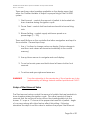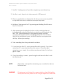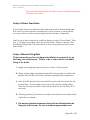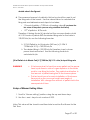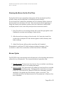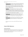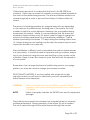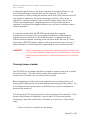
1
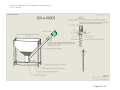
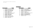
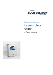
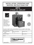
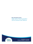
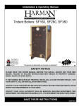
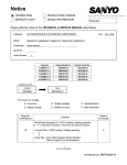
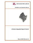
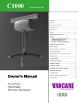
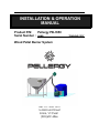
INSTALLATION & OPERATION MANUAL Product P/N: Pellergy PB-3550 Serial Number : NAME: Wood Pellet Burner System REV 6.1: MAY 2010 16 Railroad Street Barre, VT 05641 (802)659-4866 TRAINING COPY PB-3550 Wood Pellet Burner System: Installation and Operation Manual Rev 6.1, MAY 2010 Table of Contents INSTALLATION & OPERATION MANUAL Introduction Chapter ONE: Safety Chapter TWO: Installation Installation of the PB-3550 Wood Pellet Burner System Installation of the Pellet Conveyor Boiler/Furnace Room Ventilation and Maintenance Measuring Chimney Draft Electric installation General Connecting the Controller to a Voltage Source Connecting the Controller to the Thermostat Chapter THREE: Initial System Setup Filling the Conveyor Controller User Interface Description Setup of Start Amount Value Setup of Power Feed Value Setup of Burner Firing Rate Setup of Blower Setting Value Running the Burner for the First Time Burner Cycles Chapter FOUR: Maintenance General information Cleaning burner chamber Troubleshooting Burner Servicing General Technical Data Available Replacement Parts Warranty and Installation Doc Burner measured values Warranty and Installation Doc Burner measured values Installer Note Page & System Drawings 1 3 4 6 9 12 16 17 18 18 18 19 21 21 23 24 26 26 27 28 28 29 29 31 33 35 35 36 37 39 40 41 42 44 Page 2 of 50 PB-3550 Wood Pellet Burner System: Installation and Operation Manual Rev 6.1, MAY 2010 Introduction Congratulations on your purchase of a PB-3550 Wood Pellet Burner System! This manual is provided to give you an overview of the system and to provide important instruction as to the installation, operation and maintenance of the system. In order to insure years of safe, trouble-free operation, please follow the guidelines and instructions set forth in this manual. The PB-3550 wood pellet burner system is intended for installation with fully approved, regulatory compliant domestic hot water boilers and furnaces. The PB-3550 is intended for use with ¼” Premium Wood Pellets certified by the Pellet Fuels Institute. The Burner System uses an external pellet conveyor to transport pellets from both standard Pellergy and third party external pellet bins/hoppers to burner. Following the installation of your system, the Pellergy trained certified installation professional (Certified Installer) will review with you the operation of your system, record important information as to the installed system, give you a copy of this manual and ask that you acknowledge receipt of such. If at any time you have questions or concerns, please contact Pellergy customer service, or your Certified Installer. Page 3 of 50 PB-3550 Wood Pellet Burner System: Installation and Operation Manual Rev 6.1, MAY 2010 Chapter ONE: Safety Remember: Safety does not happen on its own. You must follow the instructions set forth in this manual as well as those given to you by the certified installer and mandated by applicable local, state and federal codes. Adhering to these guidelines does not insure accident-free operation; however, not following the instruction, guidance and procedures presented herein increases the risk of loss of property, bodily injury, and even death. Please follow this manual carefully and contact Pellergy or your Certified Installer with any questions. The PB-3550 wood pellet burner system shall be installed by Pellergy trained certified installation professionals ONLY. Any unauthorized installation of the PB-3550 system voids the product warranty and may result in loss of property, bodily injury to personnel, and even death. Pellergy systems are sold only through Pellergy trained and authorized personnel. If you have purchased this system on the secondary market please contact Pellergy or your local Certified Installer for assistance in installation and important operational instruction. A listing of Pellergy trained certified installation professionals is maintained by Pellergy LLC. Please contact Pellergy customer service for an up-todate listing of professionals in your area. FOR YOUR SAFETY, PLEASE READ THIS ENTIRE MANUAL PRIOR TO INSTALLING AND/OR OPERATING THE PB 3550 WOOD PELLET BURNER SYSTEM. FAILURE TO FOLLOW THESE INSTRUCTIONS AND LOCAL CODE MAY RESULT IN DAMAGE OR LOSS OF PROPERTY, BODILY INJURY, AND EVEN DEATH. PLEASE KEEP THIS MANUAL FOR FUTURE REFERENCE Page 4 of 50 PB-3550 Wood Pellet Burner System: Installation and Operation Manual Rev 6.1, MAY 2010 Overview This Safety summary, and this manual, has been prepared to insure the PB-3550 System is installed, operated and maintained in a safe manner for personnel and to prevent unnecessary damage or loss of property. Precautions described in this and subsequent chapters should be observed during system installation, operation and maintenance. Definitions The following definitions of warnings, cautions, and notes are provided and shall be applied throughout this document: WARNING! CAUTION! WARNING: A warning identifies a clear danger to person(s) performing that procedure and personnel utilizing the system; failure to abide by a warning may result in damage or loss of property, bodily injury, and even death. CAUTION: A caution identifies risk of damage to equipment; failure to abide by a caution may result in permanent damage to the system and/or auxiliary equipment. NOTE: A note is used to highlight essential procedures, conditions, or statements that convey important instructional data to the reader. The system must be installed by a Pellergy Trained Certified Installation Professional ONLY. Never introduce a fuel other than Premium Wood Pellets into the system. There is a high risk of fire and explosion if gasoline, diesel fuel, kerosene, #2 heating oil or any other flammable liquid or material is used in the system; always avoid the use of these. Do not store combustible materials within 24” of the PB3550 burner Items may fall into an open pellet hopper and cause damage to the auger. Keep all objects clear of the pellet Page 5 of 50 PB-3550 Wood Pellet Burner System: Installation and Operation Manual Rev 6.1, MAY 2010 hopper opening. NOTE Pellets other than Premium Wood Pellets may cause system damage. Use only ¼” Premium Wood Pellets as designated and certified by the Pellet Fuels Institute. When installed as the only automatic source of central heat within a home or business check with your existing insurance, mortgage provider, and local building codes before installing the PB-3550 wood pellet burner system. Fully understand any limitations or restrictions that may apply as to the use of a solid fuel fired central heating unit. Chapter TWO: Installation WARNING! The PB-3550 wood pellet burner system shall be installed by Pellergy trained certified installation professionals ONLY. Any unauthorized installation of the PB-3550 system voids the product warranty and may result in damage or loss of property, injury to personnel, and even death. The PB-3550 Wood Pellet Burner System installs through the use of a custom mounting plate to the boiler front that is provided by Pellergy. An initial site survey of the intended host boiler or furnace and environment must be performed. Pellergy must provide the Certified Installer with the appropriate mounting plate for the application. The PB-3550 must be installed to fire the boiler in the same manner as the original oil burner. In order to accomplish this, the following guidelines must be followed: 1. The system must only be used in oil and wood fired boilers and furnaces. a. Not all boilers/furnaces are good candidates for use with a Pellergy System. The boiler must be closely evaluated by a Certified Installer for compatibility. In addition to meeting Page 6 of 50 PB-3550 Wood Pellet Burner System: Installation and Operation Manual Rev 6.1, MAY 2010 local, state and regulatory codes, the boiler/furnace must accommodate ash buildup between cleanings. This ash will accumulate within the boiler/furnace. The host boiler/furnace must be easily cleaned on a more regular basis than when firing on oil. Additionally, the boiler/furnace must allow for this buildup without compromise to the combustion gas flow within the heat exchanger surfaces of the boiler. WARNING! Failure to properly match a PB-3550 system with a host boiler/furnace can result property damage, injury and even death. 2. The system requires a firebox with: a. Minimum volume of 1FT3. b. Minimum depth of 12 inches as measured from the burner face to the back wall of the firebox. c. A minimum width that can easily accommodate the largest outer diameter of the PB-3550, 7 inches. 3. The burner must be installed into the firebox such that: a. A minimum of 2-inches of clearance from the opening of the burner to the floor of the firebox is provided. b. The centerline of the burner shall be positioned at the same centerline as the pre-existing oil burner to insure proper firing of the boiler or furnace. This will insure enough volume for the collection of ash between cleanings. 4. Not all boilers and furnaces are completely compatible with the Pellergy PB-3550 system. For example, boilers designed for pressurized firebox firing on oil systems are not suitable for use with the pellet burner even if the above firebox requirements are met. In some cases, the boiler will need to be rated1.5-2.0 times larger in input Btu´s in order to gain required Btu output and handle the heat load. The Certified Installer must evaluate the total heat load requirement against the installation requirements detailed herein and apply his/her experience with the particular boiler/furnace type during the initial evaluation of the system. Page 7 of 50 PB-3550 Wood Pellet Burner System: Installation and Operation Manual Rev 6.1, MAY 2010 WARNING! Installation of the PB-3550 shall result in no permanent modification to the existing boiler or furnace. All existing safety interlocks and controls must be utilized. If the installation of the PB-3550 will require such modification as the cutting away of insulation, gasket material, steel or any other part of the existing boiler or furnace: Do not attempt to use the PB-3550 on this system. FIREBOX (minimum 1FT3) BOILER PB-3550 BURNER Burner Centerline matches preexisting burner centerline Refractory Insulation Required Min. Firebox depth 12” Min. Clearance 2” Figure 2.1: Typical installation showing minimum internal dimensions and clearances. CAUTION! If the manufacturer’s data on the boiler or furnace to be fired using the PB-3550 Wood Pellet Burner System gives specific instruction NOT to convert the unit to solid fuel, please consult the boiler or furnace manufacturer before installation. Page 8 of 50 PB-3550 Wood Pellet Burner System: Installation and Operation Manual Rev 6.1, MAY 2010 NOTE When installing the PB-3550, take note of the surrounding area with regard to the regular maintenance of the burner. The burner requires regular maintenance and ease of access to the burner for this maintenance will be more convenient for the user. The PB-3550 Wood Pellet Burner System requires the use of an existing, up to date chimney sized appropriately for the boiler or furnace used. An existing masonry or Class A metal chimney may be used provided that it meets local code. When no local code exists, follow the requirements of NFPA 211: “Standard for Chimneys, Fireplaces, Vents, and Solid FuelBurning Appliances”. Certain Canadian Codes may require the chimney be fully relined prior to installation. WARNING! If the boiler and/or furnace is not properly cleaned and maintained, chimney temperatures can approach or exceed 1000° F and create unsafe conditions that can lead to fire. Regular cleaning and maintenance routines must be followed. CAUTION! The PB-3550 should not be used in a system installed in a chimney serving multiple boilers or furnaces unless specifically allowed by local Code AND the use of an interlock system is used such that only one unit may use the chimney at any given time. The PB-3550 should not be used in conjunction with a flu damper. If a flue damper exists in the existing system, as is typical for wood fired boilers and furnaces, the damper must be removed prior to the installation of the PB-3550. The existing chimney should be cleaned and inspected prior to installation of the PB-3550 Wood Pellet Burner System. NOTE Installation of the PB-3550 Wood Pellet Burner System 1. Plan ahead. Insure proper installation, operation and maintenance space is available before beginning installation. Insure the PB-3550 burner can be disassembled for proper cleaning in the intended installation space. 2. Remove oil burner and oil burner mounting plate (if applicable). Page 9 of 50 PB-3550 Wood Pellet Burner System: Installation and Operation Manual Rev 6.1, MAY 2010 3. Inspect all gaskets and mounting surfaces. Replace any gasket material that is damaged, or that is worn or deteriorated to the point where a proper seal can not be made. WARNING! The PB-3550 Wood Pellet Burner System must not be operated with the boiler or Furnace door open! If The PB-3550 is mounted to a hinged door, an optional interlock switch is required. This interlock is intended to prevent the burner from operating with the door open. Contact the boiler or furnace manufacturer for details regarding to and availability of the interlock switch. 4. Fit the custom PB-3550 burner mounting plate to the boiler or furnace. (For specific fitting details refer to documentation included with the custom mounting plate) 5. After mounting the burner mounting plate to the boiler or furnace, inspect to insure that the interface between mounting plate and boiler or furnace form an air tight seal. 6. Assemble the PB-3550 burner to the mounting plate. 7. Refractory material installed on the boiler door or mounting plate shall be maintained as originally installed by the boiler or furnace manufacturer to limit the surface temperature. Pellet Auger Pellet Hopper Auger Motor Electronic Controller (550LBS Capacity) Drop Tube Pellet Feed Tube Boiler or Furnace (Not Included with System, Show for Clarity) Wood Pellet Burner Figure 2.2a: System Overview Page 10 of 50 PB-3550 Wood Pellet Burner System: Installation and Operation Manual Rev 6.1, MAY 2010 WOOD/OIL BOILER MOUNTING PLATE (WILL VARY BY BOILER) PB-3550 BURNER BURNER TO MOUNTING PLATE GASKET MOUNTING PLATE TO BOILER GASKET (WILL VARY BY BOILER) Figure 2.2: Burner assembled to mounting plate. See Figure 2.3a below for a typical layout of a Pellergy System with a Burnham MPO231, six section boiler Page 11 of 50 PB-3550 Wood Pellet Burner System: Installation and Operation Manual Rev 6.1, MAY 2010 24” Smoke Pipe 17” 6‐Section Burnham MPO Boiler (MPO231‐TB) 35” Pellergy Burner mounted to Boiler Door Service Envelope (required for cleanout) All boiler clearances must be maintained and local codes followed in any installation. Per Burnham guidelines, a min of 6” clearance on sides and top and 18” to the rear are to be maintained. 20.5” 24” 10’ (Max) 3’ (Min) Pellet Hopper (shown at max distance from boiler) Pellet Hopper Location (continues for full 270°) 48” 24” Figure 2.3a: PB-3550 burner mounted to a Burnham MPO231-TB Six Section Boiler Installation of the Pellet Conveyor When determining the location of the pellet conveyor mounting position, the location of both the PB-3550 burner and the pellet hopper must be considered 1. The conveyor is designed to be hung from a single-point overhead anchor. Inspect the overhead in the vicinity of the PB-3550 burner and select a suitable point for the overhead anchor. The conveyor must be positioned such that: a. The overhead anchor point must be able to continuously support a minimum of 100 pounds. See Figure 2.3 below Page 12 of 50 PB-3550 Wood Pellet Burner System: Installation and Operation Manual Rev 6.1, MAY 2010 b. The conveyor must be mounted such that the drop tube is a minimum of 15-inches above the PB-3550 pellet feed tube opening (Max 30-inches) See Figure 2.3 below c. The conveyor must be mounted such that the drop tube is a minimum of 6-inches laterally away from the PB-3550 pellet feed tube opening (Maximum of 12-inches). See Figure 2.3 below ANCHOR POINT CONVEYOR CHAIN 15-30” 40-50º 6-12” Figure 2.3: Conveyor mounting details. WARNING! The pellet feed conveyor assembly can weigh as much as 100-pounds when in operation and filled with pellets. Insure a suitable overhead anchor point from which to hang the conveyor. Do not direct-couple the conveyor drop tube to the PB3550 pellet feed tube without the use of the supplied flexible plastic drop tube assembly. This tube acts as a back-burn safety device. Page 13 of 50 PB-3550 Wood Pellet Burner System: Installation and Operation Manual Rev 6.1, MAY 2010 NOTE Do not install the conveyor drop tube directly over the PB3550 pellet feed tube. Misalignment is intended and acts as a safety feature. The feed conveyor must not exceed 10 FT in length. Adding to the length of the feed conveyor will result in burner malfunction. 2. When positioning the pellet hopper and installing the conveyor into the pellet hopper: a. The conveyor must be installed at an angle between 40-50º as shown in Figure 2.3 above. b. The feed conveyor auger tube must not exceed 10 FT in length. The feed conveyor may be cut to a desired length provided that final length is able to meet all other installation requirements of the conveyor. 3. Install the overhead anchor and hang the conveyor using the included conveyor chain as in Figure 2.3 above. 4. Install the conveyor into the pellet hopper, ensure there is clearance between the auger spiral and the bottom of the hopper of at least 1-inch. If the conveyor auger makes contact with the bottom of the hopper, damage can occur. Refer to Figure 2.4 below. Page 14 of 50 PB-3550 Wood Pellet Burner System: Installation and Operation Manual Rev 6.1, MAY 2010 SPIRAL AUGER TO HOPPER FLOOR CLEARANCE 1” MIN. Figure 2.4: Conveyor and Auger assembly details showing the auger spiral WARNING! The Pellet hopper and/or pellet storage must not be installed within 24-inches of the PB-3550 wood pellet burner. Keep all combustible materials a minimum of 24-inches from the PB-3550 wood pellet burner Follow all boiler and furnace manufacturer’s required combustible keep out zones. 5. If using an alternate pellet storage silo or hopper, follow manufacturer’s installation instructions. Do not install or store any combustible or flammable materials within 24-inches of the PB-3550 burner. Page 15 of 50 PB-3550 Wood Pellet Burner System: Installation and Operation Manual Rev 6.1, MAY 2010 Boiler/Furnace Room Ventilation and Maintenance 1. The PB-3550 must be supplied with adequate fresh air for combustion. a. The room in which the boiler or furnace is installed should be supplied with a minimum 2-inch diameter fresh air inlet vented to atmosphere. This ventilation must come from outside the building, not from an adjoining room or enclosed space. b. The installation room must not at any time be under a vacuum, which can be caused by other appliances such as whole house fans, other combustion devices requiring supply air, and the like. An improperly ventilated room can lead to incomplete combustion, lower efficiency and even the production of harmful gasses within the living space. WARNING! Proper ventilation must be provided for the PB-3550 wood pellet burner system. 2. The immediate area surrounding the PB-3550 wood pellet burner system and host boiler/furnace must be kept clean and free of combustible and/or flammable materials at all times. 3. Additionally, the loading of pellets into the pellet hopper may result in large amounts of dust. Care must be taken to remove dust from the boiler/furnace room to prevent a dust fire or explosion. WARNING! Handling of wood pellets can cause dust to be released into the air. Proper ventilation must be provided to avoid personal injury and possible dust fire and/or explosion. Page 16 of 50 PB-3550 Wood Pellet Burner System: Installation and Operation Manual Rev 6.1, MAY 2010 Measuring Chimney Draft The PB-3550 requires a negative draft chimney installation. Draft must be measured with a proper draft gauge. Prior to measuring draft, be sure that the boiler/furnace is air tight and all leak points are sealed. Air leaks can give faulty results and can cause problems when operating the PB-3550. The draft measurement is to be taken at the exhaust gas outlet of the boiler/furnace at the exhaust pipe connection. Draft should be between -0.03 in-H2O to -0.10 in-H2O. If the Draft is more than -0.10 in-H2O, or likely to exceed -0.10 in-H2O a draft regulator (barometric control unit) is recommended for use. WARNING! Improper draft can lead to potentially hazardous conditions. Chimney draft must be within system limitations at all time. The boiler and chimney must be kept clean to maintain proper draft. If draft is less an -0.03 in-H2O , a forced draft blower, or draft inducer, can be installed to create proper draft. Install per manufacturer’s recommendation and guidelines. Following initial installation of the PB-3550, proper cleanout maintenance in the boiler/furnace as well as the chimney is a necessity. Fly ash, clinkers and buildup within the chimney and boiler/furnace can cause blockage and improper operational draft. Refer to Chapter Four: Maintenance for information on cleanout. Page 17 of 50 PB-3550 Wood Pellet Burner System: Installation and Operation Manual Rev 6.1, MAY 2010 Electric installation General There are two electrical connections required to connect the PB-3550: 1.) Connection to a 120V AC Power Source 2.) Connection to a thermostat Connecting the Controller to a Voltage Source 1. The PB-3550 connects to household line voltage: 120V AC, 60Hz for operation. The voltage source for the PB-3550 must: a. Be connected to the same point as specified for the oil burner by the boiler and furnace manufacturer. This is to insure that all controls, cut-out switches and safety devices remain active. b. Be installed such that all devices used to cut power to the burner in the event of high temperature, high pressure, low water, etc. remain between the voltage source and the PB3550 such that any of these devices will cut power to the wood pellet burner system if required. WARNING! All safety controls required to protect the boiler/furnace from overheating, overpressure, low water, and others must be installed between the voltage source and the PB-3550. 2. The PB-3550 should be serviced from a dedicated branch circuit breaker rated at not more than 15A. The system 120V AC Main Fuse is rated at 6A. CAUTION! Do not connect the PLC controller directly to household voltage. The controller is a low voltage device that must be supplied power from the AC to DC converter. Page 18 of 50 PB-3550 Wood Pellet Burner System: Installation and Operation Manual Rev 6.1, MAY 2010 3. Input Voltage is supplied to the PB-3550 at the bottom of the electronics control box using the entry point labeled and cable strain relief provided. Follow connection marks for Line, Neutral and Ground Connections. WARNING! The PB-3550 must be connected to a proper ground connection as labeled. Connecting the Controller to the Thermostat 1. The PB-3550 connects to a standard low voltage control, normally open dry contact thermostat. System firing will be controlled by the demand called for by the thermostat. 2. The thermostat connects to the PB-3550 through the side of the electronics control box using the entry point labeled and cable strain relief provided. The Thermostat connects directly to the PLC Controller and to a dedicated, labeled connector within the controller, located at the 24V fuse output (Top, Left side of the electronics box). 3. An optional 120V AC input relay is available for installations where the existing control circuit provides direct 120V AC to the existing oil burner for operation. IF required, this relay is installed within an exterior control box. Input 120V AC control voltage where labeled on the relay and connect the Normally Open (N.O.) relay outputs to the thermostat inputs in the electronics control box as detailed in #2 above. WARNING! The PB-3550 shall be connected using one power source only. The power source for the PB-3550 must be provided through the existing boiler/furnace safety interlock features. Page 19 of 50 PB-3550 Wood Pellet Burner System: Installation and Operation Manual Rev 6.1, MAY 2010 Figure 2.5: Electrical Schematic Page 20 of 50 PB-3550 Wood Pellet Burner System: Installation and Operation Manual Rev 6.1, MAY 2010 Chapter THREE: Initial System Setup Filling the Conveyor The conveyor must be filled with pellets in order for the PB-3550 system to function properly. Typical scenarios where conveyor filling is required are: 1. At initial system set up 2. After maintenance is performed that requires disassembly of the conveyor or removal of the conveyor from the pellet hopper. 3. In the event that the system is permitted to run out of pellets Scenario 1 and 2 above should only be performed by a Certified Installer. Scenario 3 may be performed by a homeowner that has received instruction from their Certified Installer. WARNING! The act of filling the conveyor will cause the system to activate and mechanical components to be put in motion. Prior to filling, be sure that all systems are free and clear of obstruction to reduce the risk of entanglement. Filling at Initial system set up and post maintenance: 1. Scroll to “start amount” position using the up and down keys. 2. Use the + and – keys to set a time amount of 30 seconds 3. Initiate a “start amount test” by pressing and holding the left arrow key for 4 seconds. 4. After pressing and holding the button on the controller the red indicator lamp under the electronics control box will illuminate, the text “TEST” will be displayed on the graphic display, and the conveyor will begin to rotate, priming the conveyor. Wait for the test period to end, at which time the conveyor motor will stop, before proceeding. The blower will run for the first 180-seconds of the test period. This is normal. Care should be taken to insure that all systems are free and clear of obstruction with the blower Page 21 of 50 PB-3550 Wood Pellet Burner System: Installation and Operation Manual Rev 6.1, MAY 2010 and blower cooling fan to reduce the risk of entanglement. 5. Press right arrow button once and repeat steps 3 and 4 as required to fill the conveyor with pellets. This will be evident as pellets begin to drop regularly from the drop tube. 6. Once the conveyor is filled, press the right arrow button to exit the Test Mode. Filling after running the system out of pellets: 1. Prior to refilling the conveyor, the system must be placed in the “OFF” mode by depressing the “OK” button. 2. The error message must be cleared by cycling the system power OFF. 3. Switch the burner back ON. When the burner system is switched back ON, the error will be cleared and the system will be in the OFF mode as indicated on the graphic display. 4. Scroll to “starting amount” position using the up and down keys. 5. Initiat a “start amount test” by pressing and holding the left arrow key for 4 seconds. 6. After pressing and holding the button on the controller the red indicator lamp under the electronics control box will illuminate, the text “TEST” will be displayed on the graphic display, and the conveyor will begin to rotate, priming the conveyor. Wait for the test period to end, at which time the conveyor motor will stop, before proceeding. 7. Press right arrow button once and repeat steps 5 and 6 as required to fill the conveyor with pellets. This will be evident Page 22 of 50 PB-3550 Wood Pellet Burner System: Installation and Operation Manual Rev 6.1, MAY 2010 as pellets begin to drop regularly from the drop tube. 8. Once the conveyor is filled, press the right arrow button to exit the Test Mode. 9. Power down system by turning the main power switch on left side of the electronics control box to the off position. 10. Clean the burn chamber as there may be unburned pellets in the burn chamber. 11. Power system on by turning the main power switch on left side of the electronics control box to the on position to resume normal operations Controller User Interface Description Figure 3.1: Image of the controller buttons and display Page 23 of 50 PB-3550 Wood Pellet Burner System: Installation and Operation Manual Rev 6.1, MAY 2010 There are three value headings available on the display menu that allow the Certified Installer to adjust for proper firing of the PM-3550 system 1. Start Amount - controls the amount of pellets to be loaded into burn chamber during the ignition cycle 2. Power Feed - controls fuel feed rate and results in burner firing rate 3. Blower Setting - controls supply air blower speed as a percentage (1 – 100) There are 8 Buttons on the controller that allow navigation and input to the controller. General input keys: 1. Use +/- buttons to change values on display (Values change in real time and values are stored automatically in the control memory) 2. Use up/down arrows to navigate and scroll display. 3. To run test mode, press and hold down left arrow button for 4 seconds 4. To exit test mode press right arrow button once WARNING! Functions describe in the remainder of the chapter are to be performed by a Pellergy trained certified professional ONLY!! Setup of Start Amount Value The Start amount value controls the amount of pellets that are loaded into burn chamber during the ignition cycle. This value is period of time in seconds that the conveyor motor will run thus loading pellets into the burner. 2.1 cups or 17 ounces is the proper start amount of pellets. Angle of conveyor along with other factors affect this setting. Following describes the steps to set this value to achieve the proper Start Amount. Page 24 of 50 PB-3550 Wood Pellet Burner System: Installation and Operation Manual Rev 6.1, MAY 2010 1. Scroll to “starting amount” position using the up and down keys. 2. Use the + and – keys to set a time amount of 30 seconds 3. Place a graduated container, that will allow you to measure pellets in cups and or ounces, under the conveyor drop tube 4. Initiate a “start amount test” by pressing and holding the left arrow key for 4 seconds. 5. After pressing and holding the button on the controller the red indicator lamp under the electronics control box will illuminate, the text “TEST” will be displayed on the graphic display, and the conveyor will begin to rotate, dropping pellets into the container. Wait for the test period to end, at which time the conveyor motor will stop, before proceeding. 6. Take a reading from the graduated container. 7. If you have less that 2.1 cups increase the start amount. If you have more than 2.1 cups decrease the start amount. Press the right arrow key once, empty the container and repeat steps 3-6 until you get 2.1 cups. 8. Once the setting is correct, press the right scroll arrow button to exit the Test Mode. NOTE! Remember to empty the measuring cup or collection device between tests. WARNING! If the burner is set to feed too many pellets on the initial ignition feed (Start Amount) there is a risk of a gas explosion in the boiler. Page 25 of 50 PB-3550 Wood Pellet Burner System: Installation and Operation Manual Rev 6.1, MAY 2010 Pay particular attention to the Start Amount of pellets being fed to the burner system. Setup of Power Feed Value Power Feed Value controls fuel feed rate and results in burner firing rate. The value is in seconds and corresponds to the number of seconds the conveyor will run continuously during the Heat Mode of operation Use the up or down arrows to scroll the display to show Power Feed. Then use +/- buttons to set right value the power feed. Refer to section “Set the Burner Firiing Rate” for instructions on how to properly set the Power Feed value. Setup of Burner Firing Rate This test must be run for each burner installation to accurately set up the firing rate of the burner. Failure to do so can result in over/under firing of the boiler. 1. Begin by setting the power feed to a value of 2.5 seconds. 2. Place a fairly large container beneath the drop pipe to collect the pellets that will drop from the conveyor during the test sequence. 3. Press the left arrow button and hold for 4 seconds to run test for the power feed. The test period runs for six (6) minutes during which time the conveyor feeds in every 20 seconds for the set time of 2.5 seconds. 4. Following the six (6) minute run measure the amount of pellets in the collection container. 5. The amount of pellets measured during this test will determine the firing rate of the burner. Be sure to measure appropriately and Page 26 of 50 PB-3550 Wood Pellet Burner System: Installation and Operation Manual Rev 6.1, MAY 2010 double check the figures! 6. The measured amount of pellets in this test cycle will be used to set the firing rate of the burner. Use the values below to calculate the firing rate and determine next steps to be taken: o 1 Pound of pellets = 7,900 btu of heating value (If you know the btu value of the pellets you are using substitute that value) o 1 FT3 of pellets = 40 Pounds Therefore, if during the six (6) minute test the conveyor feeds a total of 2.10 Pounds of pellets AND the desired firing rate on the boiler is 125,000 btu/hr, use the following formulas: 2.10 LB Pellets in six (6) minutes (360 sec) = [2.10lb X 7,900btu/lb X 10] = 165,900 btu/hr The desired firing is 125,000 btu/hr therefore, input a lower power feed and re-test. Use the following formula to calculate btu/hr [LB of Pellets in 6-Minute Test] X [7,900 btu/lb] X 10 = btu/hr input firing rate WARNING! If the burner is set to feed too many pellets on the power feed cycle there is a risk of a gas explosion in the boiler and/or over-firing the boiler. Pay particular attention to the amount of pellets being fed to the burner system. This test must be run for each installation of the burner. Items such as the conveyor length and angle of installation WILL change the amount of pellets fed in the same period of time. Setup of Blower Setting Value 1. Scroll to “blower setting” position using the up and down keys. 2. Use the + and – keys to set a value of 50%. Note: This value will be tuned in real time later in section Run Burner for the First Time Page 27 of 50 PB-3550 Wood Pellet Burner System: Installation and Operation Manual Rev 6.1, MAY 2010 Running the Burner for the First Time During the first burner operation stack gases will be analyzed and the blower value may be adjusted to achieve proper burning. Do not insert the combustion analyzer into the chimney before burner is Heat mode for a minimum of 5 min. This is because in the beginning of firing the burner can produce smoke that can cause the combustion analyzer probe to be come dirty and produce erroneous results. 1. Push Ok button to run burner. Burner will cycle through Ignition and Stabilization modes and settling in Heat mode. 2. After burner has running on Heat mode for 5 minutes, insert the combustion analyzer into the exhaust gases outlet/chimney and take readings 3. Adjust the blower setting value more/less air if needed. Remember to wait least 3-5 min between making changes to the controller to allow the combustion within the burner to stabilize. Burner Cycles The PB-3550 is fully automated and will respond to the heating demand as called for by a thermostat. The normal modes of operation are: 1. Standby Mode: The burner is shut down; the controller is monitoring the thermostat input for a heating demand. 2. Ignition Mode: The thermostat has called for heat and the controller has begun the heating cycle. During ignition mode the conveyor loads the Start Amount of Pellets into the burn chamber, power is applied to the igniter and the blower cycles on and off. The controller monitors the flame sensor for the presence of flame in the burn chamber. Page 28 of 50 PB-3550 Wood Pellet Burner System: Installation and Operation Manual Rev 6.1, MAY 2010 3. Stabilization Mode: The flame sensor has indicated the presence of a flame in the burn chamber. The igniter is shut off and the blower is ramped up to a constant speed. Half way through the cycle, pellets will be fed into the burn chamber at a low rate. The flame sensor constantly monitors for the presence and intensity of flame. If the flame begins to fail, pellets will not be fed into the system until the flame intensity recovers. 4. Heat Mode: Following a preset amount of time, the controller places the system into High Heat mode. Pellets are fed at the Power Feed Rate and the blower is ramped up to the set blower rate for full, complete combustion. Pellets will be fed into the system every 20-second at the Power Feed Rate and the blower will remain at a constant speed. The flame sensor is constantly monitoring for the presence of a full flame in the burn chamber. 5. End Blow Mode: The thermostat has ended the demand for heat and the controller begins the shut-down mode. Pellets are no longer fed into the burn chamber; however, the blower remains at a constant speed. The flame sensor is monitoring the flame intensity. 6. Afterblow Mode: The flame sensor has indicated to the controller that the flame in the burn chamber is out. The blower ramps up to the maximum output level for a preset time of no less than 3minutes. The blower is then shut down and the PB-3550 enters Standby Mode. Chapter FOUR: Maintenance General information The PB-3550 requires regular general maintenance for proper operation. There are two types of regular maintenance: One accomplished by the homeowner (burner cleanout) and the other by the certified trained installer (boiler/furnace cleanout). Page 29 of 50 PB-3550 Wood Pellet Burner System: Installation and Operation Manual Rev 6.1, MAY 2010 Clinkers are byproducts of combustion that form in the PB-3550 burn chamber. These form as a result of naturally occurring mineral impurities in the wood of the pellets being burned. The burner chamber needs to be cleaned regularly in order to prevent the buildup of clinkers within the system. The amount of cleaning required on a regular basis will vary depending on the amount of pellets burned, the firing rate of the system, the total number of start/stop cycles between cleanings, the wood pellets being burned and the season. Initially, it is recommended that the burner be cleared of clinker buildup every 3-4 days in order to begin to gauge the amount of buildup experienced in your particular installation. Typical cleanout periodicity is between 7-10 days during the heating season and 10-14 days during the non heating months when the system may be used to provide domestic hot water only. Every installation is different, and wood pellets from various manufacturers can vary widely. In the initial weeks of operation with your system, keep a log of your cleanouts using the hours and start/stop cycle counter on the controller. Begin to learn the cleanout cycle that best suits the operation of your system. Remember, if you change the brand of pellet being used or your usage pattern, you may also need to change your cleanout routine. PELLET QUALITY MATTERS! If you burn pellets with a high ash or high impurity content you will have to clean both your burn chamber and boiler/furnace more frequently. CAUTION! Failure to properly clean the PB-3550 can result in failed operation of the system resulting in property loss or damage due to freezing. NOTE Failure to properly maintain the PB-3550 can result in equipment damage. The boiler/furnace needs to be cleaned on a regularly basis by a trained, certified professional. During operation of the burner, fly ash is created. This ash is carried throughout the boiler/furnace through the normal Page 30 of 50 PB-3550 Wood Pellet Burner System: Installation and Operation Manual Rev 6.1, MAY 2010 combustion gas flow from the burn chamber, through the firebox, over the heat exchanger surfaces and out the chimney. Fly ash will accumulate on every horizontal surface within the boiler/furnace and will also begin to adhere to the heat exchanger surfaces. This causes a reduction in system efficiency due to the insulative effect the ash has within the boiler/furnace. Regular cleanout of the boiler/furnace is required to maintain the highest efficiency as well as to maintain proper system operation. It is recommended that the PB-3550 owner execute a regular maintenance contract with your certified installation professional for regular cleanout services on the boiler/furnace. In general, oil fired boilers/furnaces require cleaning once per year when fired on oil; when fired using a PB-3550 system cleanout may be required every 3-4 tons of pellets burned, or more frequently depending on your particular boiler. WARNING! Failure to properly and regularly clean the boiler/furnace may result in high chimney temperatures or system failure. Have the boiler/furnace cleaned by a trained professional on a regular basis. Cleaning burner chamber The PB-3550 burn chamber requires the regular, manual removal of clinker and ash buildup. This task can be easily accomplished by the homeowner in as little as one minute with practice. Before beginning to clean the burn chamber, be sure the system is not running by looking at the controller display and listening to the system. Do not interrupt a burn cycle; rather, wait till the burn cycle is complete to perform the cleanout. Turn the system OFF using the switch on the left side of the controller. If the burner has just been in operation, wait at least 10-20 minutes before cleaning to allow the combustion chamber to cool down. Follow these steps: 1. Remove the two cables from the burner, Page 31 of 50 PB-3550 Wood Pellet Burner System: Installation and Operation Manual Rev 6.1, MAY 2010 2. Loosen the two wing nuts on the top of the burner, 3. Remove the wing nut on the back side of the burner, 4. Remove the green burner cover, 5. Release the two quick latches located on each side of the burner, 6. Bend burner forward slightly, rotating about the drop and lift from assembly, 7. Remove the burner chamber by sliding it from within the assembly, 8. Dump contents of the burner chamber into a properly rated ash can. Scrape or brush the chamber as necessary and re-assemble the burner. WARNING! Never store ashes and/or clinkers inside the building or in a nonmetallic container. Always use a container specifically rated for the removal of ash. Ashes and clinkers within the burner can appear to be cool; however, once exposed to air and broken up during the cleaning process can be hot enough to start a fire. CAUTION! Burner components may be very hot. Always check the temperature of the burn chamber before removing from the system. Use gloves or other protective gear to avoid injury. Page 32 of 50 PB-3550 Wood Pellet Burner System: Installation and Operation Manual Rev 6.1, MAY 2010 Troubleshooting The PB-3550 burner system is fully automated and will provide feedback to the operator if an error occurs. Use the guide below to troubleshoot and remedy any automated shutdown of the system. If the system has entered an error mode it is for a reason. DO NOT simply restart the controller without taking action to remedy the initial cause of the error. The table below provides a guide to errors, potential cause and remedy. Error Message -Ignition Error Potential Cause 1. Burn Chamber clogged or filled with clinkers and ash Remedy 1. Clean burn chamber and restart system 3. Failed Ignitor 2. Load pellet bin and fill auger tube 4. Failed Flame Sensor 3. CP* install of new ignitor 5. Failed Blower 4. CP* install of new flame sensor 2. Out of Pellets 6. Improper draft in system 5. CP* install of new blower 6. CP* checking of draft and cleaning of boiler -Firing Down Error 1. Burn Chamber clogged or filled with clinkers and ash 2. Out of Pellets 3. Failed Flame Sensor 4. Failed Blower 5. Improper draft in system 1. Clean burn chamber and restart system 2. Load pellet bin and fill auger tube 3. CP* install of new flame sensor 4. CP* install of new blower Page 33 of 50 PB-3550 Wood Pellet Burner System: Installation and Operation Manual Rev 6.1, MAY 2010 5. CP* checking of draft and cleaning of boiler -No Error Message, system inoperable 1. Loss of or no main power to system 1. Check power source including any safety interlocks on boiler/furnace. Pellets collect in drop tube 1. Burn Chamber clogged or filled with clinkers and ash 1. Clean burn chamber and restart system No pellets feeding into burner 1. Pellet bin out of pellets 1. Fill pellet bin 2. Pellets bridging in pellet bin due to improperly stored pellets or exposure to water 3. Damage to conveyor system 2. Remove pellets from bin and replenish with new pellets 3. inspect conveyor at the connection of the conveyor to the feed motor. CP* repair of conveyor * CP = Certified Trained Professional Page 34 of 50 PB-3550 Wood Pellet Burner System: Installation and Operation Manual Rev 6.1, MAY 2010 Burner Servicing General Burners servicing is authorized by Pellergy Certified Installation Professionals only. Any alteration performed by a non-Pellergy trained individual voids the warranty. Burner failures caused of uncertified services or installations, wrong done service or installation voids warranty and Pellergy LLC do not take any responsibility of any damage caused by this. Also look local regulation of electric work before chance igniter or any electrical part of the burner where there is chance to cause electric shock. Page 35 of 50 PB-3550 Wood Pellet Burner System: Installation and Operation Manual Rev 6.1, MAY 2010 Technical Data Dimension out side of boiler : Dimension of combustion chamber: Ø7.0” x 8” mm Average burning rate: c:a 95% Max energy output: 180,000 btu/hr Min energy output: 100,000 btu/hr Voltage: Weight: 120VAC/60Hz/600W(max) 55LBS (burner) Certifications The Pellergy Pellet Replacement Burner for steam boilers, hot water boilers and hot air furnaces with existing oil burners was tested and found to comply with the intent of test standards: UL 391, ETLM 78-1, CAN/CSA-B 366.1; ASTM E-1509, standards for Solid Fuel Fired Central Furnaces. This application is only for the use of replacing existing oil burning firing units in existing furnaces. Thus, the Pellergy Pellet Solid Fuel Replacement Burner is eligible for listing and labeling under Guardian’s Factory Inspection Program when applied for by the customer, Pellergy LLC. Complete drawings and test data are on file at Guardian and at the manufacturer. Tested by Guardian Fire Testing Laboratories, Inc. (ISO/IEC 17025:2005, Certificate #AT-1247) Page 36 of 50 PB-3550 Wood Pellet Burner System: Installation and Operation Manual Rev 6.1, MAY 2010 Available Replacement Parts Igniter* Blower* Flame sensor* Optional Relay Conroller Thermal Safety Switch Fuses (Controller) Burner chamber Quick release latches (side of the burner) *The following items are provided to Certified Installation Professionals as a part of the Critical Spares Kit. Page 37 of 50 PB-3550 Wood Pellet Burner System: Installation and Operation Manual Rev 6.1, MAY 2010 Page 38 of 50 PB-3550 Wood Pellet Burner System: Installation and Operation Manual Rev 6.1, MAY 2010 Warranty and Installation Doc During installation this document must be completed correctly for warranty to be valid. One Copy remains with the system, the other is transmitted to Pellergy. Both sides must be complete. Installed product: PB-3550 Wood Pellet Burner System Production No:___________________________________________ Installation date:_________________________________________ Installed to:_______________________________________________ Name:___________________________________________________ Address:__________________________________________________ Zip code:_________________________________________________ Phone number:____________________________________________ Installation Company:______________________________________ Name:_____________________________________________________ Address:____________________________________________________ Zip code:___________________________________________________ Phone:_____________________________________________________ (Customer Copy) Page 39 of 50 PB-3550 Wood Pellet Burner System: Installation and Operation Manual Rev 6.1, MAY 2010 Burner measured values (Customer Copy) Chimney draft (Cold)__________________[in-H2O] Chimney draft (Hot)___________________[in-H2O] Temperature out side house_______________[°F] Values at Power Feed Stack gas temperature _______________[°F] CO________________[ppm] <300 ppm O2 _________________[%] CO2 _________________ [%] 10~12% CO2 Blower Setting setting _________________[%] 1-100 Start Amount ____________________[seconds] Power feed 1 ____________________[seconds] Date of Installation: ___________________ Job Number/Name: ___________________ (Customer Copy) Page 40 of 50 PB-3550 Wood Pellet Burner System: Installation and Operation Manual Rev 6.1, MAY 2010 Warranty and Installation Doc (This copy must be sent to Pellergy LLC within 10-days of installation along with the burner setup data; complete both sides) Installed product: PB-3550 Wood Pellet Burner System Production No:___________________________________________ Installation date:_________________________________________ Installed to:_______________________________________________ Name:___________________________________________________ Address:__________________________________________________ Zip code:_________________________________________________ Phone number:____________________________________________ Installation Company:______________________________________ Name:_____________________________________________________ Address:____________________________________________________ Zip code:___________________________________________________ Phone:_____________________________________________________ (This copy must be sent to Pellergy LLC within 10-days of installation) Page 41 of 50 PB-3550 Wood Pellet Burner System: Installation and Operation Manual Rev 6.1, MAY 2010 Burner measured values Chimney draft (Cold)__________________[in-H2O] Chimney draft (Hot)___________________[in-H2O] Temperature out side house_______________[°F] Values at Power Feed Stack gas temperature _______________[°F] CO________________[ppm] <300 ppm O2 _________________[%] CO2 _________________ [%] 10~12% CO2 Blower Setting setting _________________[%] 1-100 Start Amount ____________________[seconds] Power feed 1 ____________________[seconds] Date of Installation: ___________________ Job Number/Name: ___________________ Page 42 of 50 PB-3550 Wood Pellet Burner System: Installation and Operation Manual Rev 6.1, MAY 2010 WARRANTY Pellergy LLC backs its products to be free from defects in material or workmanship, under normal use and service, for a period of one year from the date of sales invoice to the customer. Installation documentation must be provided to Pellergy LLC within 10-days of sales invoice date. If defective in material or workmanship, during the warranty period, Pellergy LLC will, at its sole discretion, repair or replace the product as described below. The warranty above constitutes the entire warranty with respect to Pellergy LLC products. PELLERGY LLC MAKES NO OTHER WARRANTY, EXPRESSED OR IMPLIED. No employee, agent, dealer, or other person is authorized to give any warranty on behalf of Pellergy LLC. This warranty does not apply if the product has been altered in any way after leaving the factory. Pellergy LLC and its agents assume no liability for “resultant damages of any kind” arising from the use of its products. In addition, the manufacturer and its warranty administrator shall be held free and harmless from liability from damage to property related to the operation, proper or improper, of the equipment. THERE ARE NO WARRANTIES WHICH EXTEND BEYOND THE DESCRIPTION OF WARRANTY HEREIN DESCRIBED. This warranty applies only if the system is installed and operated as recommended in the user’s manual, and installed by a Pellergy LLC trained professional following all applicable requirements: local, state, county or other regulatory/governmental and those imposed by Pellergy LLC. THESE WARRANTIES WILL NOT APPLY if abuse, accident, improper installation, negligence, or use beyond rated capacity causes damage. Any claim under this warranty should be made to the dealer/Certified Installer from whom this appliance was purchased. THIS WARRANTY IS LIMITED TO DEFECTIVE PARTS - REPAIR AND/OR REPLACEMENT IS AT Pellergy LLC’s OPTION AND EXCLUDES ANY INCIDENTAL AND CONSEQUENTIAL DAMAGES CONNECTED THEREWITH. WARRANTY EXCLUSIONS: Failure due, but not limited to, fire, lightning, acts of God, power failures and/or surges, rust, corrosion and venting problems are not covered. Damage and/or repairs including but not limited to; fuses, knobs, glass, plastic, paint, and related duct work/chimney are not covered. Also excluded from this warranty are consumable or normal wear. Excluded in this warranty is any coverage of the existing boiler or heating system being converted. Additional or unusual utility bills incurred due to any malfunction or defect in equipment and the labor cost of gaining access to or removal of a unit that requires special tools or equipment are not covered. Maintenance needed to keep the system in “good operating condition” is not covered. This includes, but is not limited to, cleaning, adjustment of controls and customer education. Labor, materials, expenses and/or equipment needed to comply with law and/or regulations set forth by any governmental agencies are not covered. This Warranty provides specific legal rights and the consumer may have other rights that vary from state to state. In the event of change in ownership, the remaining portion of this warranty may be transferred to the new owner by sending the new owner information and a transfer fee of $35.00 US to the Pellergy LLC. If the system is sold independently it MUST installed by a Pellergy LLC trained professional. The remedies set forth herein are exclusive and the liability of seller with respect to any contract or sale or anything done in connection therewith, whether in Contract, in tort, under any warranty, or otherwise, shall not, except as herein expressly provided, exceed the price of the equipment or part of which such liability is based. The above represents the complete warranty, which is given in connection with the burner units, manufactured by Pellergy LLC. No other commitments, verbal or otherwise, shall apply except by a written addendum to this warranty. Page 43 of 50 PB-3550 Wood Pellet Burner System: Installation and Operation Manual Rev 6.1, MAY 2010 Installer Note Page & System Drawings Page 44 of 50 PB-3550 Wood Pellet Burner System: Installation and Operation Manual Rev 6.1, MAY 2010 Page 45 of 50 PB-3550 Wood Pellet Burner System: Installation and Operation Manual Rev 6.1, MAY 2010 Drawing 200-A-00001 Reference 1 2 3 4 5 6 7 8 9 10 11 12 13 14 15 16 17 Part Number 300-W-00001 700-N-00004 700-W-00001 300-W-00002 300-M-00005 300-E-00001 300-M-00006 700-B-00002 700-W-00002 300-M-00007 300-M-00002 400-M-00002 400-M-00001 400-E-00002 400-E-00001 700-B-00001 400-M-00003 Description 50KW, INNER BURNER WINGNUT, 1/4-20 WASHER, 18-8 SST 1/4" FLAT 50KW, OUTER BURNER NOZZLE, IGNITOR IGNITOR, BURNER BRACKET, NOZZLE SCREW, 18-8 SST 8-32 X 3/8" BH WASHER, 18-8 SST #8 FLAT BRACKET, IGNITOR HOUSING, IAS 50 KW BURNER LATCH, ADJUSTABLE DRAW STRAIN RELIEF, PVDF .27-.47 SENSOR, FLAME BLOWER, 1TDP2 SCREW, 18-8 SST 1/4-20 X 1/2" BH STRAIN RELIEF, NYLON 2 CONDUCTOR .12" Reference 18 19 20 21 22 23 24 25 26 27 28 29 30 31 32 33 34 35 Part Number 300-M-00004 300-W-00004 400-E-00004 700-B-00005 400-E-00005 300-M-00008 400-E-00008 700-B-00007 300-M-00010 300-M-00009 700-B-00004 400-E-00003 300-W-00003 700-B-00006 400-M-00004 300-M-00011 700-N-00002 300-M-00003 Description BRACKET, 50 KW OUTER COVER MOUNTING 50KW OUTER COVER PLUG, 3-PIN SCREW, 18-8 SST 4-40 X 1/2" BH PLUG, 6-PIN BRACKET, ELECTRICAL CONNECTOR TERMINAL BLOCK -6P SCREW, 18-8 SST 6-32 X 1" BH COVER, TEMP SWITCH BRACKET, TEMP SWITCH CABLE SCREW, 18-8 SST 6-32 X 1/4" BH SWITCH, FAN LIMIT IAS, FEED TUBE SCREW, 18-8 SST 1/4-20 X 3/8" BH STRAIN RELIEF, NYLON .08-.20 COVER, ELECTRICAL CONNECTOR NUT, 18-8 SST #8-32 DEFLECTOR, IAS FEED TUBE Page 46 of 50 PB-3550 Wood Pellet Burner System: Installation and Operation Manual Rev 6.1, MAY 2010 Page 47 of 50 PB-3550 Wood Pellet Burner System: Installation and Operation Manual Rev 6.1, MAY 2010 Page 48 of 50 PB-3550 Wood Pellet Burner System: Installation and Operation Manual Rev 6.1, MAY 2010 Page 49 of 50 PB-3550 Wood Pellet Burner System: Installation and Operation Manual Rev 6.1, MAY 2010 Drawing 200-A-00003 Reference 1 2 3 4 5 6 7 8 9 10 11 12 13 14 15 16 17 Part Number 300-M-00017 700-B-00008 700-W-00001 700-N-00005 300-M-00001 400-M-00010 300-W-00007 300-W-00006 700-B-00002 700-W-00002 300-M-00019 300-M-00021 300-M-00022 300-M-00018 700-B-00009 400-M-00011 400-E-00016 Description WALL, HOPPER INNER BOLT, GRADE 5 1/4-20 X 5/8" WASHER, 18-8 SST 1/4" FLAT NUT, 1/4-20 WITH NYLOK WALL, HOPPER OUTER CLAMP, 3" PIPE JOINING ASSEMBLY, TUBE SHROUD, MOTOR SCREW, 18-8 SST 8-32 X 3/8" BH WASHER, 18-8 SST #8 FLAT TUBE, CONVEYOR BRACE, HOPPER LEG, HOPPER COLLECTOR, HOPPER BOLT, GRADE 5 1/4-20 X 1/2" EDGING, SERRATED PE MOTOR, DRIVE Reference 18 19 20 21 22 23 24 25 26 27 28 29 30 31 Part Number 700-B-00011 700-L-00004 700-M-00001 400-M-00008 700-B-00012 700-L-00003 300-M-00020 300-M-00012 700-S-00001 300-M-00013 400-M-00012 400-M-00007 700-B-00008 400-M-00009 Description SHCS, 10-32 X 5/8" SPLIT LOCKWASHER, #10 CIRCLIP, EXTERNAL STANDOFF, UNTHREADED BRASS BOLT, GRADE 5 1/4-20 X 2.5" SPLIT LOCKWASHER, #1/4 PIN, HOOK COUPLER, MOTOR SETSCREW, CUP POINT 1/4-20 X 5/16 PLATE, MOTOR MOUNTING FITTING, CONDUIT 3/8" BEARING, MOUNTED BALL BOLT, GRADE 5 1/4-20 X 5/8" AUGER Page 50 of 50