1
SiBE18 - 821
E-Series
[Applied Models]
Super Multi Plus : Heat Pump
SiBE18-821
SUPER MULTI PLUS
E-Series
zHeat Pump
Indoor Unit
FTXG25EV1BW(S)
FTXG35EV1BW(S)
CTXG50EV1BW(S)
FTXS20G2V1B
FTXS25G2V1B
FTXS35G2V1B
FTXS42G2V1B
FTXS50G2V1B
FTXS60FV1B
FTXS71FV1B
FDXS50CVMB
FDXS60CVMB
FDXS25EAVMB
FDXS35EAVMB
FVXS25FV1B
FVXS35FV1B
FVXS50FV1B
FLXS25BAVMB
FLXS35BAVMB
FLXS50BAVMB
FLXS60BAVMB
FHQ35BVV1B
FHQ50BVV1B
FHQ60BVV1B
FFQ25B8V1B
FFQ35B8V1B
FFQ50B8V1B
FFQ60B8V1B
Outdoor Unit
RMXS112E8V1B
RMXS140E8V1B
RMXS160E8V1B
Table of Contents
BPMKS967B2B
BPMKS967B3B
i
SiBE18-821
1. Introduction ........................................................................................... vii
1.1 Safety Cautions ...................................................................................... vii
1.2 Used Icons .............................................................................................. xi
Part 1 List of Functions ................................................................ 1
1. List of Functions ......................................................................................2
Part 2 Specifications .................................................................... 9
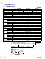
1. Specifications ........................................................................................10
1.1 Outdoor Units .........................................................................................10
1.2 BP Unit ...................................................................................................11
1.3 Indoor Units ............................................................................................12
Part 3 Printed Circuit Board Connector Wiring Diagram ........... 21
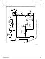
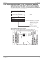
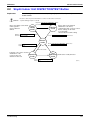
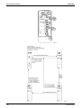
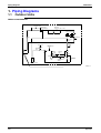
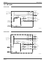
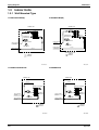
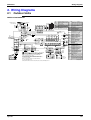
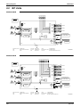
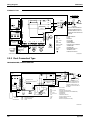
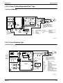
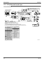
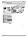
1. Printed Circuit Board Connector Wiring Diagram..................................22
1.1
1.2
1.3
1.4
1.5
1.6
1.7
1.8
1.9
1.10
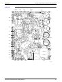
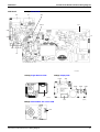
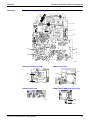
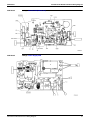
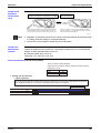
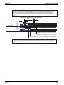
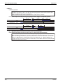
Outdoor Unit RMXS 112/140/160 E8V1B ..............................................22
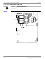
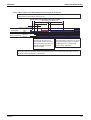
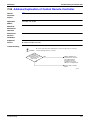
Branch Provider Unit ..............................................................................27
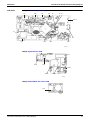
FTXG25~35E, CTXG50E .......................................................................28
Wall Mounted Type 20-50 Class - G Series ...........................................30
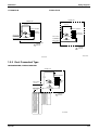
Wall Mounted Type 60/71 Class - F Series............................................32
Duct Connected Type.............................................................................34
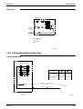
Floor / Ceiling Suspended Dual Type.....................................................36
Floor Standing Type ...............................................................................39
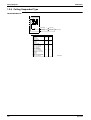
Ceiling Mounted Cassette 600×600 Type ..............................................42
Ceiling Suspended Type ........................................................................44
Part 4 Refrigerant Circuit ........................................................... 47
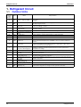
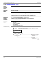
1. Refrigerant Circuit .................................................................................48
1.1 Outdoor Units .........................................................................................48
1.2 BP Units .................................................................................................50
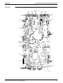
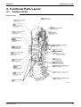
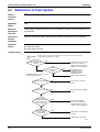
2. Functional Parts Layout ........................................................................51
2.1 Outdoor Units .........................................................................................51
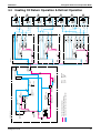
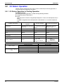
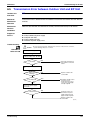
3. Refrigerant Flow for Each Operation Mode...........................................52
3.1
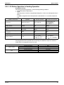
3.2
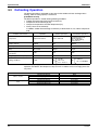
3.3
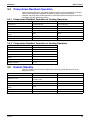
3.4
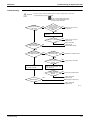
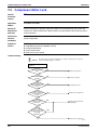
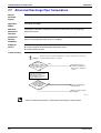
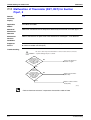
Cooling Operation ..................................................................................52
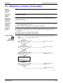
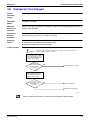
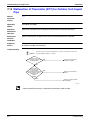
Heating Operation ..................................................................................53
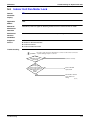
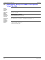
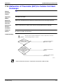
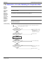
Cooling Oil Return Operation .................................................................54
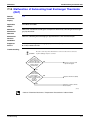
Heating Oil Return Operation & Defrost Operation ................................55
Part 5 Function............................................................................ 57
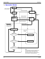
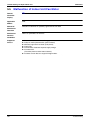
1. Operation Mode ....................................................................................58
2. Basic Control.........................................................................................59
2.1
2.2
2.3
2.4
Normal Operation ...................................................................................59
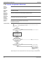
Compressor PI Control...........................................................................60
Electronic Expansion Valve PI Control...................................................63
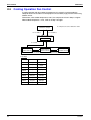
Cooling Operation Fan Control...............................................................64
3. Special Control......................................................................................65
3.1 Startup Control .......................................................................................65
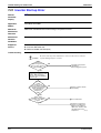
3.2 Oil Return Operation ..............................................................................66
ii
Table of Contents
SiBE18-821
3.3
3.4
3.5
3.6
Defrosting Operation ..............................................................................68
Pump-down Residual Operation ............................................................69
Restart Standby......................................................................................69
Stopping Operation ................................................................................70
4. Protection Control .................................................................................71
4.1
4.2
4.3
4.4
4.5
4.6
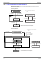
High Pressure Protection Control...........................................................71
Low Pressure Protection Control............................................................72
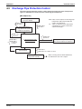
Discharge Pipe Protection Control .........................................................73
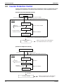
Inverter Protection Control .....................................................................74
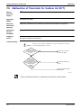
Freeze-up Protection Control .................................................................75
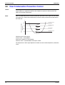
Dew Condensation Prevention Control ..................................................76
5. Other Control.........................................................................................77
5.1 Demand Operation .................................................................................77
5.2 Heating Operation Prohibition ................................................................77
6. BP Unit Control .....................................................................................78
6.1
6.2
6.3
6.4
6.5
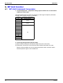
BP Unit Command Conversion ..............................................................78
BP Unit Electronic Expansion Valve Control ..........................................79
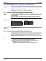
SH Control in Cooling Operation ............................................................81
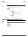
SC Control in Heating Operation............................................................82
Heat Exchanger Isothermal Control in Heating Operation .....................82
7. Indoor Unit (RA Models)........................................................................83
7.1
7.2
7.3
7.4
7.5
7.6
7.7
7.8
7.9
7.10
7.11
7.12
Power-Airflow Dual Flaps, Wide Angle Louvers and Auto-Swing ..........83
Fan Speed Control for Indoor Units........................................................85
Programme Dry Function .......................................................................86
Automatic Operation...............................................................................87
Thermostat Control.................................................................................88
Night Set Mode.......................................................................................89
ECONO Mode ........................................................................................90
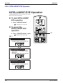
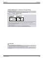
INTELLIGENT EYE (FTXS-F) ................................................................91
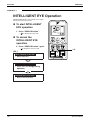
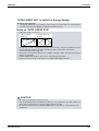
2 AREA INTELLIGENT EYE (FTXS-G)..................................................93
HOME LEAVE Operation .......................................................................95
Inverter POWERFUL Operation .............................................................97
Other Functions......................................................................................98
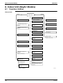
8. Indoor Unit (SkyAir Models) ................................................................100
8.1 Function Outline ...................................................................................100
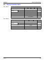
8.2 Electric Function Parts .........................................................................101
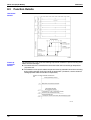
8.3 Function Details....................................................................................102
Part 6 Test Operation ............................................................... 115
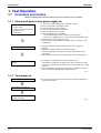
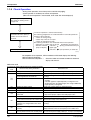
1. Test Operation ....................................................................................116
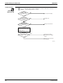
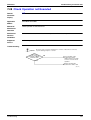
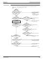
1.1 Procedure and Outline .........................................................................116
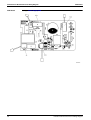
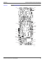
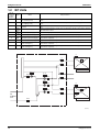
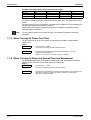
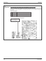
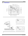
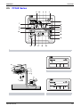
2. Outdoor Unit PCB Layout....................................................................132
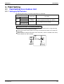
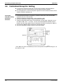
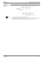
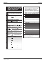
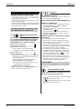
3. Field Setting ........................................................................................133
3.1 Field Setting from Outdoor Unit............................................................133
3.2 Detail of Setting Mode ..........................................................................143
4. Field Setting for SkyAir Indoor Unit .....................................................152
4.1
4.2
4.3
4.4
4.5
Table of Contents
Explanation...........................................................................................152
Field Setting .........................................................................................153
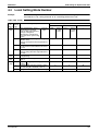
Initial Setting Contents .........................................................................154
Local Setting Mode Number.................................................................155
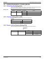
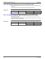
Detailed Explanation of Setting Modes ................................................157
iii
SiBE18-821
4.6 Centralized Group No. Setting .............................................................162
4.7 Maintenance Mode Setting...................................................................164
5. Test Operation and Field Setting for RA Indoor Unit...........................166
5.1 Test Operation from the Remote Controller .........................................166
5.2 Jumper Settings ...................................................................................168
Part 7 Operation Manual ........................................................... 169
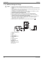
1. System Configuration..........................................................................170
1.1 Operation Instructions ..........................................................................170
2. Instruction............................................................................................171
2.1
2.2
2.3
2.4
2.5
RMXS Series........................................................................................171
FTXG-E, CTXG-E, FTXS-F, FDXS-C(E), FLK(X)S-B Series ...............172
FTXS-G, FVXS-F Series ......................................................................198
FHQ-B Series .......................................................................................222
FFQ-B Series .......................................................................................231
Part 8 Troubleshooting ............................................................. 241
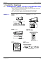
1. Caution for Diagnosis..........................................................................243
1.1
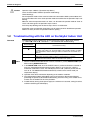
1.2
1.3
1.4
Troubleshooting with the Operation Lamp (RA Indoor Unit) ................243
Troubleshooting with the LED on the SkyAir Indoor Unit .....................244
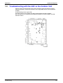
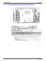
Troubleshooting with the LED on the Outdoor Unit..............................245
Troubleshooting with the LED on the BP Unit ......................................246
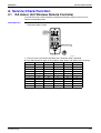
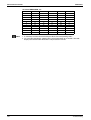
2. Service Check Function ......................................................................247
2.1
2.2
2.3
2.4
2.5
2.6
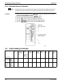
RA Indoor Unit Wireless Remote Controller.........................................247
SkyAir Indoor Unit INSPECTION/TEST Button....................................253
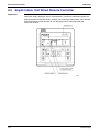
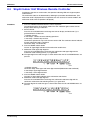
SkyAir Indoor Unit Wired Remote Controller........................................254
SkyAir Indoor Unit Wireless Remote Controller ...................................255
Sky Air Indoor Unit Error Codes and LED Indication............................257
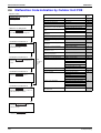
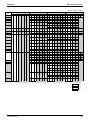
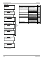
Malfunction Code Indication by Outdoor Unit PCB ..............................258
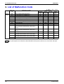
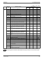
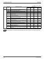
3. List of Malfunction Code......................................................................262
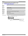
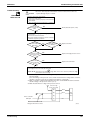
4. Troubleshooting for RA Indoor Unit.....................................................265
4.1
4.2
4.3
4.4
4.5
Indoor Unit PCB Abnormality ...............................................................265
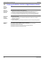
Freeze-up Protection Control or High Pressure Control.......................266
Fan Motor or Related Abnormality .......................................................268
Thermistor or Related Abnormality (Indoor Unit)..................................271
Check ...................................................................................................272
5. Troubleshooting for SkyAir Indoor Unit ...............................................275
5.1
5.2
5.3
5.4
5.5
5.6
5.7
5.8
5.9
5.10
5.11
5.12
5.13
iv
Indoor Unit PCB Abnormality ...............................................................275
Malfunction of Drain Water Level System (Float Type)........................276
Malfunction of Drain System ................................................................278
Indoor Unit Fan Motor Lock..................................................................279
Malfunction of Indoor Unit Fan Motor ...................................................280
Swing Flap Motor Malfunction / Lock ...................................................282
Malfunction of Capacity Setting............................................................284
Malfunction of Heat Exchanger Thermistor (R2T)................................285
Malfunction of Heat Exchanger Thermistor (R3T)................................286
Malfunction of Suction Air Thermistor ..................................................287
Malfunction of Remote Controller Thermistor.......................................288
Transmission Error (between Indoor Unit and Remote Controller) ......289
Transmission Error (between Main and Sub Remote Controller).........290
Table of Contents
SiBE18-821
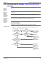
5.14 Malfunction of Field Setting Switch ......................................................291
5.15 Check ...................................................................................................292
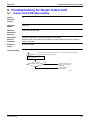
6. Troubleshooting for BP Unit ................................................................294
6.1
6.2
6.3
6.4
6.5
6.6
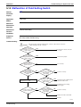
Malfunction of Electronic Expansion Valve ..........................................294
Faulty BP Unit PCB ..............................................................................295
Faulty BP Liquid or Gas Pipe Thermistor .............................................296
Transmission Error between Indoor Unit and BP Unit..........................297
Transmission Error between Outdoor Unit and BP Unit.......................299
Check ...................................................................................................300
7. Troubleshooting for Outdoor Unit........................................................301
7.1
7.2
7.3
7.4
7.5
7.6
7.7
7.8
7.9
7.10
7.11
7.12
7.13
7.14
7.15
7.16
7.17
7.18
7.19
7.20
7.21
7.22
7.23
7.24
7.25
7.26
7.27
7.28
7.29
7.30
7.31
7.32
7.33
7.34
7.35
Table of Contents
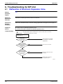
Faulty Outdoor Unit PCB......................................................................301
Actuation of High Pressure Switch .......................................................302
Actuation of Low Pressure Sensor .......................................................304
Compressor Motor Lock .......................................................................306
Malfunction of Outdoor Unit Fan Motor ................................................307
Malfunction of Moving Part of Electronic Expansion Valve
(Y1E, Y3E) ...........................................................................................308
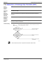
Abnormal Discharge Pipe Temperature ...............................................310
Refrigerant Overcharged......................................................................311
Malfunction of Thermistor for Outdoor Air (R1T) ..................................312
Malfunction of Discharge Pipe Thermistor (R2T) .................................313
Malfunction of Thermistor (R3T, R5T) for Suction Pipe1, 2 .................314
Malfunction of Thermistor (R4T) for Outdoor Unit Heat Exchanger .....315
Malfunction of Thermistor (R7T) for Outdoor Unit Liquid Pipe .............316
Malfunction of Subcooling Heat Exchanger Thermistor (R6T) .............317
Malfunction of High Pressure Sensor...................................................318
Malfunction of Low Pressure Sensor....................................................319
Malfunction of PCB...............................................................................320
Malfunction of Inverter Radiating Fin Temperature Rise......................321
Inverter Compressor Abnormal ............................................................322
Inverter Current Abnormal....................................................................323
Inverter Start up Error...........................................................................324
Malfunction of Transmission between Inverter and Control PCB.........325
High Voltage of Capacitor in Main Inverter Circuit ...............................326
Malfunction of Inverter Radiating Fin Temperature Rise Sensor .........327
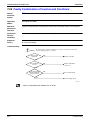
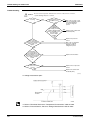
Faulty Combination of Inverter and Fan Driver ....................................328
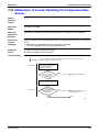
Low Pressure Drop Due to Refrigerant Shortage or
Electronic Expansion Valve Failure......................................................329
Power Supply Insufficient or Instantaneous Failure .............................331
Check Operation not Executed ............................................................333
Malfunction of Transmission between
Indoor Units and Outdoor Units............................................................334
Malfunction of Transmission between
Remote Controller and Indoor Unit.......................................................336
Malfunction of Transmission between
Main and Sub Remote Controllers .......................................................337
Malfunction of Transmission between
Indoor and Outdoor Units in the Same System....................................338
Excessive Number of Indoor Units .......................................................340
Address Duplication of Central Remote Controller...............................341
Malfunction of Transmission between
Central Remote Controller and Indoor Unit ..........................................342
v
SiBE18-821
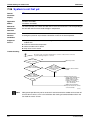
7.36 System is not Set yet............................................................................344
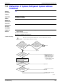
7.37 Malfunction of System, Refrigerant System Address Undefined..........345
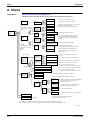
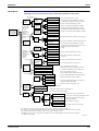
8. Check ..................................................................................................346
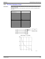
9. Thermistor Resistance / Temperature Characteristics........................349
10.Pressure Sensor .................................................................................351
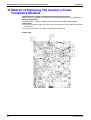
11.Method of Replacing The Inverter’s Power Transistors Modules........352
Part 9 Appendix......................................................................... 355
1. Piping Diagrams..................................................................................356
1.1 Outdoor Units .......................................................................................356
1.2 BP Units ...............................................................................................357
1.3 Indoor Units ..........................................................................................358
2. Wiring Diagrams..................................................................................363
2.1 Outdoor Units .......................................................................................363
2.2 BP Units ...............................................................................................364
2.3 Indoor Units ..........................................................................................365
Index
............................................................................................. i
Drawings & Flow Charts .............................................................. vii
vi
Table of Contents
SiBE18-821
Introduction
1. Introduction
1.1
Safety Cautions
Cautions and
Warnings
Be sure to read the following safety cautions before conducting repair work.
The caution items are classified into “
Warning” and “
Caution”. The “
Warning”
items are especially important since they can lead to death or serious injury if they are not
followed closely. The “
Caution” items can also lead to serious accidents under some
conditions if they are not followed. Therefore, be sure to observe all the safety caution items
described below.
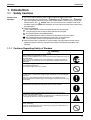
About the pictograms
This symbol indicates the item for which caution must be exercised.
The pictogram shows the item to which attention must be paid.
This symbol indicates the prohibited action.
The prohibited item or action is shown in the illustration or near the symbol.
This symbol indicates the action that must be taken, or the instruction.
The instruction is shown in the illustration or near the symbol.
After the repair work is complete, be sure to conduct a test operation to ensure that the
equipment operates normally, and explain the cautions for operating the product to the
customer.
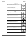
1.1.1 Cautions Regarding Safety of Workers
Warning
Be sure to disconnect the power cable plug from the plug socket before
disassembling the equipment for repair.
Working on the equipment that is connected to the power supply may cause an
electrical shook.
If it is necessary to supply power to the equipment to conduct the repair or
inspecting the circuits, do not touch any electrically charged sections of the
equipment.
If the refrigerant gas is discharged during the repair work, do not touch the
discharged refrigerant gas.
The refrigerant gas may cause frostbite.
When disconnecting the suction or discharge pipe of the compressor at the
welded section, evacuate the refrigerant gas completely at a well-ventilated
place first.
If there is a gas remaining inside the compressor, the refrigerant gas or
refrigerating machine oil discharges when the pipe is disconnected, and it may
cause injury.
If the refrigerant gas leaks during the repair work, ventilate the area. The
refrigerant gas may generate toxic gases when it contacts flames.
The step-up capacitor supplies high-voltage electricity to the electrical
components of the outdoor unit.
Be sure to discharge the capacitor completely before conducting repair work.
A charged capacitor may cause an electrical shock.
Do not start or stop the air conditioner operation by plugging or unplugging the
power cable plug.
Plugging or unplugging the power cable plug to operate the equipment may
cause an electrical shock or fire.
vii
Introduction
SiBE18-821
Warning
Be sure to wear a safety helmet, gloves, and a safety belt when working at a
high place (more than 2m). Insufficient safety measures may cause a fall
accident.
In case of R410A refrigerant models, be sure to use pipes, flare nuts and tools
for the exclusive use of the R410A refrigerant.
The use of materials for R22 refrigerant models may cause a serious accident
such as a damage of refrigerant cycle as well as an equipment failure.
Caution
Do not repair the electrical components with wet hands.
Working on the equipment with wet hands may cause an electrical shock.
Do not clean the air conditioner by splashing water.
Washing the unit with water may cause an electrical shock.
Be sure to provide the grounding when repairing the equipment in a humid or
wet place, to avoid electrical shocks.
Be sure to turn off the power switch and unplug the power cable when cleaning
the equipment.
The internal fan rotates at a high speed, and cause injury.
Be sure to conduct repair work with appropriate tools.
The use of inappropriate tools may cause injury.
Be sure to check that the refrigerating cycle section has cooled down enough
before conducting repair work.
Working on the unit when the refrigerating cycle section is hot may cause
burns.
Use the welder in a well-ventilated place.
Using the welder in an enclosed room may cause oxygen deficiency.
viii
SiBE18-821
Introduction
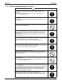
1.1.2 Cautions Regarding Safety of Users
Warning
Be sure to use parts listed in the service parts list of the applicable model and
appropriate tools to conduct repair work. Never attempt to modify the
equipment.
The use of inappropriate parts or tools may cause an electrical shock,
excessive heat generation or fire.
If the power cable and lead wires have scratches or deteriorated, be sure to
replace them.
Damaged cable and wires may cause an electrical shock, excessive heat
generation or fire.
Do not use a joined power cable or extension cable, or share the same power
outlet with other electrical appliances, since it may cause an electrical shock,
excessive heat generation or fire.
Be sure to use an exclusive power circuit for the equipment, and follow the local
technical standards related to the electrical equipment, the internal wiring
regulations, and the instruction manual for installation when conducting
electrical work.
Insufficient power circuit capacity and improper electrical work may cause an
electrical shock or fire.
Be sure to use the specified cable for wiring between the indoor and outdoor
units. Make the connections securely and route the cable properly so that there
is no force pulling the cable at the connection terminals.
Improper connections may cause excessive heat generation or fire.
When wiring between the indoor and outdoor units, make sure that the terminal
cover does not lift off or dismount because of the cable.
If the cover is not mounted properly, the terminal connection section may cause
an electrical shock, excessive heat generation or fire.
Do not damage or modify the power cable.
Damaged or modified power cable may cause an electrical shock or fire.
Placing heavy items on the power cable, and heating or pulling the power cable
may damage the cable.
Do not mix air or gas other than the specified refrigerant (R410A / R22) in the
refrigerant system.
If air enters the refrigerating system, an excessively high pressure results,
causing equipment damage and injury.
If the refrigerant gas leaks, be sure to locate the leaking point and repair it
before charging the refrigerant. After charging refrigerant, make sure that there
is no refrigerant leak.
If the leaking point cannot be located and the repair work must be stopped, be
sure to perform pump-down and close the service valve, to prevent the
refrigerant gas from leaking into the room. The refrigerant gas itself is
harmless, but it may generate toxic gases when it contacts flames, such as fan
and other heaters, stoves and ranges.
When relocating the equipment, make sure that the new installation site has
sufficient strength to withstand the weight of the equipment.
If the installation site does not have sufficient strength and if the installation
work is not conducted securely, the equipment may fall and cause injury.
ix
Introduction
SiBE18-821
Warning
Check to make sure that the power cable plug is not dirty or loose, then insert
the plug into a power outlet securely.
If the plug has dust or loose connection, it may cause an electrical shock or fire.
Be sure to install the product correctly by using the provided standard
For unitary type
installation frame.
only
Incorrect use of the installation frame and improper installation may cause the
equipment to fall, resulting in injury.
Be sure to install the product securely in the installation frame mounted on the For unitary type
window frame.
only
If the unit is not securely mounted, it may fall and cause injury.
When replacing the coin battery in the remote controller, be sure to disposed
of the old battery to prevent children from swallowing it.
If a child swallows the coin battery, see a doctor immediately.
Caution
Installation of a leakage breaker is necessary in some cases depending on the
conditions of the installation site, to prevent electrical shocks.
Do not install the equipment in a place where there is a possibility of
combustible gas leaks.
If the combustible gas leaks and remains around the unit, it may cause a fire.
Check to see if the parts and wires are mounted and connected properly, and
if the connections at the soldered or crimped terminals are secure.
Improper installation and connections may cause excessive heat generation,
fire or an electrical shock.
If the installation platform or frame has corroded, replace it.
Corroded installation platform or frame may cause the unit to fall, resulting in
injury.
Check the grounding, and repair it if the equipment is not properly grounded.
Improper grounding may cause an electrical shock.
x
SiBE18-821
Introduction
Caution
Be sure to measure the insulation resistance after the repair, and make sure
that the resistance is 1 MΩ or higher.
Faulty insulation may cause an electrical shock.
Be sure to check the drainage of the indoor unit after the repair.
Faulty drainage may cause the water to enter the room and wet the furniture
and floor.
Do not tilt the unit when removing it.
The water inside the unit may spill and wet the furniture and floor.
Be sure to install the packing and seal on the installation frame properly.
For unitary type
If the packing and seal are not installed properly, water may enter the room and only
wet the furniture and floor.
1.2
Used Icons
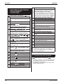
Icons are used to attract the attention of the reader to specific information. The meaning of each
icon is described in the table below:
Icon
Type of
Information
Description
Note
A “note” provides information that is not indispensable, but may
nevertheless be valuable to the reader, such as tips and tricks.
Caution
A “caution” is used when there is danger that the reader, through
incorrect manipulation, may damage equipment, loose data, get
an unexpected result or has to restart (part of) a procedure.
Warning
A “warning” is used when there is danger of personal injury.
Reference
A “reference” guides the reader to other places in this binder or
in this manual, where he/she will find additional information on a
specific topic.
Note:
Caution
Warning
xi
Introduction
xii
SiBE18-821
SiBE18-821
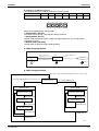
Part 1
List of Functions
1. List of Functions ......................................................................................2
List of Functions
1
List of Functions
SiBE18-821
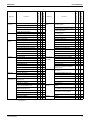
Basic
Function
Compressor
Comfortable
Airflow
Comfort
Control
Operation
Lifestyle
Convenience
Functions
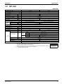
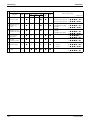
Inverter (with Inverter Power Control)
{
Operation Limit for Cooling (°CDB)
–5
~
46
Operation Limit for Heating (°CWB)
–15
~
15.5
Category
Health &
Clean
RMXS112/140/160E8V1B
Category
RMXS112/140/160E8V1B
1. List of Functions
Functions
Air Purifying Filter
—
Photocatalytic Deodorizing Filter
—
Air Purifying Filter with Photocatalytic
Deodorizing Function
—
PAM Control
—
Standby Electricity Saving
—
Titanium Apatite Photocatalytic
Air-Purifying Filter
—
Oval Scroll Compressor
{
Longlife Filter (Option)
—
Swing Compressor
—
Air Filter
—
Rotary Compressor
—
Wipe-clean Flat Panel
—
Reluctance DC Motor
{
Washable Grille
—
Power-Airflow Flap
—
Filter Cleaning Indicator
—
Power-Airflow Dual Flaps
—
Mold Proof Operation
—
Power-Airflow Diffuser
—
Heating Dry Operation
—
Wide-Angle Louvers
—
Good-Sleep Cooling Operation
—
Vertical Auto-Swing (Up and Down)
—
Horizontal Auto-Swing (Right and Left)
3-D Airflow
Weekly Timer
—
—
24-Hour On/Off Timer
—
—
72-Hour On/Off Timer
—
Comfort Airflow Mode
—
3-Step Airflow (H/P Only)
—
Timer
Worry Free
“Reliability &
Durability”
Night Set Mode
—
Auto-Restart (after Power Failure)
—
Auto Fan Speed
—
Self-Diagnosis (Digital, LED) Display
{
Indoor Unit Quiet Operation
—
Wiring-Error Check
—
Night Quiet Mode (Automatic)
{
Automatic Test Operation
{
Outdoor Unit Quiet Operation (Manual)
{
Memory Function
{
INTELLIGENT EYE
—
2 Area INTELLIGENT EYE
—
Anticorrosion Treatment of Outdoor
Heat Exchanger
{
Quick Warming Function
{
Multi-Split / Split Type Compatible
Indoor Unit
—
Hot-Start Function
—
Flexible Voltage Correspondence
—
Automatic Defrosting
{
High Ceiling Application
—
Automatic Operation
—
Chargeless
—
Programme Dry Function
—
Either Side Drain (Right or Left)
—
Fan Only
—
Power-Selection
—
5-Rooms Centralized Controller
(Option)
—
Flexibility
New POWERFUL Operation
(Non-Inverter)
—
Inverter POWERFUL Operation
—
Remote Control Adaptor
(Normal Open-Pulse Contact) (Option)
—
Priority-Room Setting
—
Remote Control Adaptor
(Normal Open Contact) (Option)
—
Cooling / Heating Mode Lock
—
Dlll-NET Compatible (Adaptor)
(Option)
—
Wireless
—
Wired
—
HOME LEAVE Operation
—
ECONO Mode
—
Indoor Unit On/Off Switch
—
Signal Reception Indicator
—
Temperature Display
—
Another Room Operation
—
Remote
Control
Remote
Controller
Note: { : Holding Functions
— : No Functions
2
List of Functions
Comfortable
Airflow
Comfort
Control
Operation
Lifestyle
Convenience
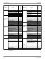
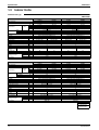
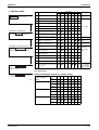
CTXG50EV1BW(S)
FTXS20-50G2V1B
Air Purifying Filter
—
—
—
—
Photocatalytic Deodorizing Filter
—
—
—
—
Air Purifying Filter with Photocatalytic
Deodorizing Function
—
—
—
Inverter (with Inverter Power Control)
{
{
{
Operation Limit for Cooling (°CDB)
—
—
—
Operation Limit for Heating (°CWB)
—
—
PAM Control
Compressor
FTXG25/35EV1BW(S)
Basic
Function
Functions
FTXS20-50G2V1B
Category
CTXG50EV1BW(S)
List of Functions
FTXG25/35EV1BW(S)
SiBE18-821
—
—
Category
Health &
Clean
Functions
Standby Electricity Saving
—
—
—
Oval Scroll Compressor
—
—
—
Titanium Apatite Photocatalytic
Air-Purifying Filter
{
{
{
Swing Compressor
—
—
—
Longlife Filter (Option)
—
—
—
Rotary Compressor
—
—
—
Air Filter
{
{
{
Reluctance DC Motor
—
—
—
Wipe-clean Flat Panel
{
{
{
Power-Airflow Flap
—
—
—
Washable Grille
—
—
—
Power-Airflow Dual Flaps
{
{
{
Filter Cleaning Indicator
—
—
—
Power-Airflow Diffuser
—
—
—
Mold Proof Operation
—
—
—
Wide-Angle Louvers
{
{
{
Heating Dry Operation
—
—
—
Vertical Auto-Swing (Up and Down)
{
{
{
Good-Sleep Cooling Operation
—
—
—
Horizontal Auto-Swing (Right and Left) {
{
{
Weekly Timer
—
—
{
3-D Airflow
{
{
{
24-Hour On/Off Timer
{
{
{
Comfort Airflow Mode
{
{
{
72-Hour On/Off Timer
—
—
—
Night Set Mode
{
{
{
Auto-Restart (after Power Failure)
{
{
{
Self-Diagnosis (Digital, LED) Display
{
{
{
Timer
3-Step Airflow (H/P Only)
—
—
—
Auto Fan Speed
{
{
{
Indoor Unit Quiet Operation
{
{
{
Night Quiet Mode (Automatic)
—
—
—
Wiring Error Check
—
—
—
Outdoor Unit Quiet Operation (Manual) —
—
—
Automatic Test Operation
—
—
—
INTELLIGENT EYE
{
{
—
Memory Function
—
—
—
2 Area INTELLIGENT EYE
—
—
{
Quick Warming Function
—
—
—
Anticorrosion Treatment of Outdoor
Heat Exchanger
—
—
—
{
Worry Free
“Reliability &
Durability”
Hot-Start Function
{
{
{
Automatic Defrosting
—
—
—
Multi-Split / Split Type Compatible
Indoor Unit
{
—
Automatic Operation
{
{
{
H/P, C/O Compatible Indoor Unit
—
—
{
Programme Dry Function
{
{
{
Flexible Voltage Correspondence
—
—
—
Fan Only
{
{
{
High Ceiling Application
—
—
—
New POWERFUL Operation
(Non-Inverter)
—
—
—
Chargeless
—
—
—
Inverter POWERFUL Operation
{
{
{
Either Side Drain (Right or Left)
{
{
{
Priority-Room Setting
—
—
—
Power Selection
—
—
—
5-Rooms Centralized Controller
(Option)
{
{
{
Flexibility
Cooling / Heating Mode Lock
—
—
— Remote
Control
HOME LEAVE Operation
—
—
—
Remote Control Adaptor
(Normal Open-Pulse Contact) (Option) {
{
{
ECONO Mode
—
—
{
Indoor Unit On/Off Switch
{
{
{
Remote Control Adaptor
(Normal Open Contact) (Option)
{
{
{
Signal Reception Indicator
{
{
—
DIII-NET Compatible (Adaptor) (Option)
{
{
{
Temperature Display
—
—
Wireless
{
{
{
Another Room Operation
—
—
— Remote
Controller
—
Wired
—
—
—
Note: { : Holding Functions
— : No Functions
List of Functions
3
Basic
Function
Compressor
Comfortable
Airflow
Comfort
Control
Operation
Lifestyle
Convenience
Functions
Inverter (with Inverter Power Control)
{
Operation Limit for Cooling (°CDB)
—
Operation Limit for Heating (°CWB)
—
PAM Control
—
Standby Electricity Saving
—
Category
Health &
Clean
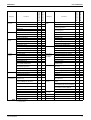
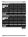
FTXS60/71FV1B
Category
SiBE18-821
FTXS60/71FV1B
List of Functions
Functions
Air Purifying Filter
—
Photocatalytic Deodorizing Filter
—
Air Purifying Filter with Photocatalytic
Deodorizing Function
—
Titanium Apatite Photocatalytic
Air-Purifying Filter
{
Oval Scroll Compressor
—
Longlife Filter (Option)
—
Swing Compressor
—
Air Filter
{
Rotary Compressor
—
Wipe-clean Flat Panel
{
Reluctance DC Motor
—
Washable Grille
—
Power-Airflow Flap
—
Filter Cleaning Indicator
—
Power-Airflow Dual Flaps
{
Mold Proof Operation
—
Power-Airflow Diffuser
—
Heating Dry Operation
—
Wide-Angle Louvers
{
Good-Sleep Cooling Operation
—
Vertical Auto-Swing (Up and Down)
{
Weekly Timer
—
Horizontal Auto-Swing (Right and Left)
{
24-Hour On/Off Timer
{
3-D Airflow
{
72-Hour On/Off Timer
—
Comfort Airflow Mode
—
Night Set Mode
{
Auto-Restart (after Power Failure)
{
3-Step Airflow (H/P Only)
—
Auto Fan Speed
{
Indoor Unit Quiet Operation
{
Timer
Worry Free
“Reliability &
Durability”
Self-Diagnosis (Digital, LED) Display
{
Wiring-Error Check
—
Night Quiet Mode (Automatic)
—
Automatic Test Operation
—
Outdoor Unit Quiet Operation (Manual)
—
Memory Function
—
INTELLIGENT EYE
{
Anticorrosion Treatment of Outdoor
Heat Exchanger
—
2 Area INTELLIGENT EYE
—
Multi-Split / Split Type Compatible
Indoor Unit
{
Quick Warming Function
—
H/P, C/O Compatible Indoor Unit
—
Hot-Start Function
{
Flexible Voltage Correspondence
—
Flexibility
Automatic Defrosting
—
High Ceiling Application
—
Automatic Operation
{
Chargeless
—
Programme Dry Function
{
Either Side Drain (Right or Left)
{
Fan Only
{
Power-Selection
—
New POWERFUL Operation
(Non-Inverter)
—
5-Rooms Centralized Controller
(Option)
{
Inverter POWERFUL Operation
{
Remote Control Adaptor
(Normal Open-Pulse Contact) (Option)
{
Priority-Room Setting
—
Remote Control Adaptor
(Normal Open Contact) (Option)
{
Cooling / Heating Mode Lock
—
DIII-NET Compatible (Adaptor)
(Option)
{
HOME LEAVE Operation
{
ECONO Mode
—
Indoor Unit On/Off Switch
{
Signal Reception Indicator
{
Temperature Display
—
Another Room Operation
—
Remote
Control
Remote
Controller
Wireless
{
Wired
—
Note: { : Holding Functions
— : No Functions
4
List of Functions
Inverter (with Inverter Power Control)
{
{
Operation Limit for Cooling (°CDB)
—
—
Operation Limit for Heating (°CWB)
Compressor
Comfortable
Airflow
Comfort
Control
Operation
Lifestyle
Convenience
—
—
—
Standby Electricity Saving
—
—
Air Purifying Filter
—
—
Photocatalytic Deodorizing Filter
—
—
Air Purifying Filter with Photocatalytic
Deodorizing Function
—
—
Titanium Apatite Photocatalytic
Air-Purifying Filter
—
—
Category
Health &
Clean
—
PAM Control
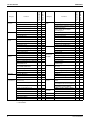
FDXS25/35EAVMB
Basic
Function
Functions
FDXS50/60CVMB
Category
FDXS25/35EAVMB
List of Functions
FDXS50/60CVMB
SiBE18-821
Functions
Oval Scroll Compressor
—
—
Longlife Filter (Option)
—
—
Swing Compressor
—
—
Air Filter
{
{
Rotary Compressor
—
—
Wipe-clean Flat Panel
—
—
Reluctance DC Motor
—
—
Washable Grille
—
—
Power-Airflow Flap
—
—
Filter Cleaning Indicator
—
—
Power-Airflow Dual Flaps
—
—
Mold Proof Operation
—
—
Power-Airflow Diffuser
—
—
Heating Dry Operation
—
—
Wide-Angle Louvers
—
—
Good-Sleep Cooling Operation
—
—
Vertical Auto-Swing (Up and Down)
—
—
Weekly Timer
—
—
Timer
Horizontal Auto-Swing (Right and Left)
—
—
24-Hour On/Off Timer
{
{
3-D Airflow
—
—
72-Hour On/Off Timer
—
—
3-Step Airflow (H/P Only)
—
—
Auto Fan Speed
{
{
Indoor Unit Quiet Operation
{
{
Night Quiet Mode (Automatic)
—
—
Worry Free
“Reliability &
Durability”
Night Set Mode
{
{
Auto-Restart (after Power Failure)
{
{
Self-Diagnosis (Digital, LED) Display
{
{
Wiring-Error Check
—
—
Outdoor Unit Quiet Operation (Manual)
—
—
Automatic Test Operation
—
—
INTELLIGENT EYE
—
—
Memory Function
—
—
Anticorrosion Treatment of Outdoor
Heat Exchanger
—
—
Multi-Split / Split Type Compatible
Indoor Unit
{
{
—
2 Area INTELLIGENT EYE
—
—
Quick Warming Function
—
—
Flexibility
Hot-Start Function
{
{
H/P, C/O Compatible Indoor Unit
—
Automatic Defrosting
—
—
Flexible Voltage Correspondence
{
{
Automatic Operation
{
{
High Ceiling Application
—
—
Programme Dry Function
{
{
Chargeless
—
—
Fan Only
{
{
Either Side Drain (Right or Left)
—
—
New POWERFUL Operation
(Non-Inverter)
—
—
Power-Selection
—
—
Inverter POWERFUL Operation
{
{
5-Rooms Centralized Controller
(Option)
{
{
Priority-Room Setting
—
—
Remote Control Adaptor
(Normal Open-Pulse Contact) (Option)
{
{
Cooling / Heating Mode Lock
—
—
Remote Control Adaptor
(Normal Open Contact) (Option)
{
{
{
HOME LEAVE Operation
{
{
ECONO Mode
—
—
Indoor Unit On/Off Switch
{
{
Signal Reception Indicator
{
{
Temperature Display
—
—
Another Room Operation
—
—
Remote
Control
Remote
Controller
DIII-NET Compatible (Adaptor) (Option)
{
Wireless
{
{
Wired
—
—
Note: { : Holding Functions
— : No Functions
List of Functions
5
{
{
Operation Limit for Cooling (°CDB)
—
—
Operation Limit for Heating (°CWB)
Compressor
Comfortable
Airflow
Comfort
Control
Operation
Lifestyle
Convenience
—
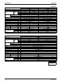
FVXS25-50FV1B
FVXS25-50FV1B
Inverter (with Inverter Power Control)
FLXS25-60BAVMB
Functions
Category
Basic
Function
SiBE18-821
FLXS25-60BAVMB
List of Functions
Air Purifying Filter
{
—
Category
Health &
Clean
Functions
Photocatalytic Deodorizing Filter
{
—
—
Air Purifying Filter with Photocatalytic
Deodorizing Function
—
—
Titanium Apatite Photocatalytic
Air-Purifying Filter
—
{
PAM Control
—
—
Standby Electricity Saving
—
—
Oval Scroll Compressor
—
—
Longlife Filter (Option)
—
—
Swing Compressor
—
—
Air Filter
{
{
Rotary Compressor
—
—
Wipe-clean Flat Panel
—
{
Reluctance DC Motor
—
—
Washable Grille
—
—
Power-Airflow Flap
—
—
Filter Cleaning Indicator
—
—
Power-Airflow Dual Flaps
—
—
Mold Proof Operation
—
—
Power-Airflow Diffuser
—
—
Heating Dry Operation
—
—
Wide-Angle Louvers
—
{
Good-Sleep Cooling Operation
—
—
Vertical Auto-Swing (Up and Down)
{
{
Weekly Timer
—
{
Horizontal Auto-Swing (Right and Left)
—
—
24-Hour On/Off Timer
{
{
3-D Airflow
—
—
72-Hour On/Off Timer
—
—
Comfort Airflow Mode
—
—
Night Set Mode
{
{
3-Step Airflow (H/P Only)
—
—
Auto-Restart (after Power Failure)
{
{
Auto Fan Speed
{
{
Self-Diagnosis (Digital, LED) Display
{
{
Indoor Unit Quiet Operation
{
{
Wiring-Error Check
—
—
Night Quiet Mode (Automatic)
—
—
Automatic Test Operation
—
—
Outdoor Unit Quiet Operation (Manual)
—
—
Memory Function
—
—
Anticorrosion Treatment of Outdoor
Heat Exchanger
—
—
Multi-Split / Split Type Compatible
Indoor Unit
{
{
—
—
Timer
Worry Free
“Reliability &
Durability”
INTELLIGENT EYE
—
—
2 Area INTELLIGENT EYE
—
—
Quick Warming Function
—
—
H/P, C/O Compatible Indoor Unit
Flexibility
Hot-Start Function
{
{
Flexible Voltage Correspondence
{
—
Automatic Defrosting
—
—
High Ceiling Application
—
—
Automatic Operation
{
{
Chargeless
—
—
Programme Dry Function
{
{
Either Side Drain (Right or Left)
—
—
Fan Only
{
{
Power-Selection
—
—
New POWERFUL Operation
(Non-Inverter)
—
—
5-Rooms Centralized Controller
(Option)
{
{
Inverter POWERFUL Operation
{
{
Remote Control Adaptor
(Normal Open-Pulse Contact) (Option)
{
{
Priority-Room Setting
—
—
Remote Control Adaptor
(Normal Open Contact) (Option)
{
{
Cooling / Heating Mode Lock
—
—
DIII-NET Compatible (Adaptor) (Option)
{
{
HOME LEAVE Operation
{
—
ECONO Mode
—
{
{
Indoor Unit On/Off Switch
{
Signal Reception Indicator
{
{
Temperature Display
—
—
Another Room Operation
—
—
Remote
Control
Remote
Controller
Wireless
{
{
Wired
—
—
Note: { : Holding Functions
— : No Functions
6
List of Functions
Inverter (with Inverter Power Control)
{
{
Operation Limit for Cooling (°CDB)
—
—
Operation Limit for Heating (°CWB)
Compressor
Comfortable
Airflow
Comfort
Control
Operation
Lifestyle
Convenience
—
FHQ35-60BVV1B
Basic
Function
Functions
FFQ25-60B8V1B
Category
FHQ35-60BVV1B
List of Functions
FFQ25-60B8V1B
SiBE18-821
Air Purifying Filter
—
—
Photocatalytic Deodorizing Filter
—
—
Air Purifying Filter with Photocatalytic
Deodorizing Function
—
—
Category
Health &
Clean
—
Functions
PAM Control
—
—
Standby Electricity Saving
—
—
Titanium Apatite Photocatalytic
Deodorizing Function
—
—
Oval Scroll Compressor
—
—
Longlife Filter (Option)
{
{
Swing Compressor
—
—
Air Filter
{
{
Rotary Compressor
—
—
Wipe-clean Flat Panel
—
—
{
Reluctance DC Motor
—
—
Washable Grille
{
Power-Airflow Flap
—
—
Filter Cleaning Indicator
{
{
Power-Airflow Dual Flaps
—
—
Mold Proof Operation
—
—
Power-Airflow Diffuser
—
—
Heating Dry Operation
—
—
Wide-Angle Louvers
—
—
Good-Sleep Cooling Operation
—
—
Vertical Auto-Swing (Up and Down)
{
{
Weekly Timer
—
—
Horizontal Auto-Swing (Right and Left)
—
—
24-Hour On/Off Timer
—
—
3-D Airflow
—
—
72-Hour On/Off Timer
{
{
Comfort Airflow Mode
—
—
Night Set Mode
—
—
{
Timer
Auto-Restart (after Power Failure)
{
Self-Diagnosis (Digital, LED) Display
{
{
Wiring-Error Check
—
—
—
Automatic Test Operation
—
—
—
Memory Function
—
—
Anticorrosion Treatment of Outdoor
Heat Exchanger
—
—
Multi-Split / Split Type Compatible
Indoor Unit
{
{
—
3-Step Airflow (H/P Only)
—
—
Auto Fan Speed
—
—
Indoor Unit Quiet Operation
—
—
Night Quiet Mode (Automatic)
—
Outdoor Unit Quiet Operation (Manual)
—
INTELLIGENT EYE
—
—
2 Area INTELLIGENT EYE
—
—
Worry Free
“Reliability &
Durability”
Flexibility
Quick Warming Function
—
—
Flexible Voltage Correspondence
—
Hot-Start Function
{
{
High Ceiling Application
—
{
Automatic Defrosting
—
—
Chargeless
—
—
Automatic Operation
{
{
Either Side Drain (Right or Left)
—
—
Programme Dry Function
{
{
Power-Selection
—
—
Fan Only
{
{
5-Rooms Centralized Controller
(Option)
—
—
New POWERFUL Operation
(Non-Inverter)
—
—
Remote Control Adaptor
(Normal Open-Pulse Contact) (Option)
—
—
Inverter POWERFUL Operation
—
—
Remote Control Adaptor
(Normal Open Contact) (Option)
—
—
Priority-Room Setting
—
—
Dlll-NET Compatible (Adaptor)
(Option)
{
{
Wireless
{
{
Wired
{
{
Cooling / Heating Mode Lock
—
—
HOME LEAVE Operation
—
—
ECONO Mode
—
—
Indoor Unit On/Off Switch
—
—
Signal Reception Indicator
—
—
Temperature Display
—
—
Another Room Operation
—
—
Remote
Control
Remote
Controller
Note: { : Holding Functions
— : No Functions
List of Functions
7
List of Functions
8
SiBE18-821
List of Functions
SiBE18-821
Part 2
Specifications
1. Specifications ........................................................................................10
1.1 Outdoor Units .........................................................................................10
1.2 BP Unit ...................................................................................................11
1.3 Indoor Units ............................................................................................12
Specifications
9
Specifications
SiBE18-821
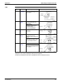
1. Specifications
1.1
Outdoor Units
50Hz 230V
Model
RMXS112E8V1B
Cooling Capacity
Heating Capacity
EER
COP
kW
kW
Cooling
Heating
Max. Total Indoor Unit Capacity Index
Min. Total Indoor Unit Capacity Index
Power Consumption
W
Running Current
A
RMXS140E8V1B
4HP
5HP
6HP
11.2
12.5
14.0
16.0
15.5
17.5
3.20
2.75
2.87
3.18
3.07
3.22
130
50
162.5
62.5
182
70
—
—
Casing Color
Daikin White
Type
Compressor
Hermetically Sealed Scroll Type
Model
Motor Output
kW
JT100G-VDL
3.0
2.5
Refrigerant
Oil
Model
Charge
L
DAPHNE FVC68D
1.5
Refrigerant
Type
Charge
kg
R-410A
4.0
Cooling
m³/min
Heating
m³/min
Airflow Rate
(H)
Fan
RMXS160E8V1B
Type
Motor Output
3.5
106
102
105
105
Propeller
70
W
Starting Current
Dimensions (H×W×D)
A
mm
Packaged Dimensions (H×W×D)
Weight
mm
kg
Gross Weight
Cooling
kg
dBA
51
130
52
54
Heating
Sound Power Cooling
dBA
dBA
53
67
54
68
55
70
Operation
Sound
Piping
Connection
Liquid
Gas
mm
mm
Drain
mm
15.9
20.2
1,345×900×320
1,524×980×420
120
φ9.52 (Flare Connection)
φ19.1 (Brazing Connection)
φ26
Both Liquid and Gas Pipes
Heat Insulation
No. of Wiring Connection
O.U. - BP
Total piping
BP - I.U.
length
System Total
m
3 For Power Supply (Including Earth Wiring), 2 For Interunit Wiring (Outdoor Unit-BP)
55
m
m
60
115
80
135
Max. piping
length
BP - I.U.
1st Branch - I.U.
m
m
15
40
Max. level
difference
O.U. - BP
O.U. - I.U.
m
m
30
30
BP - BP, I.U. - I.U.
Necessity of Additional Charge ★
22.2
m
15
kg/m
Necessary
90
145
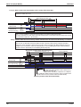
Note:
1. ★ Refrigerant charge is required. (Chargeless piping length 0m)
Formula for calculation charge : R (kg)
R = Total length (m) of liquid pipe size at φ9.5×0.054 + Total length (m) of liquid piping size at φ6.4×0.022
2. The data are based on the conditions shown in the table below.
Cooling
Heating
Indoor ; 27°CDB / 19°CWB
Outdoor ; 35°CDB
Conversion Formulae
kcal/h=kW×860
Btu/h=kW×3414
cfm=m³/min×35.3
Piping Length
Indoor ; 20°CDB
Outdoor ; 7°CDB / 6°CWB
Main Piping : 5m
Branch Piping : 3m
Level difference : 0m
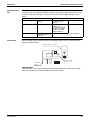
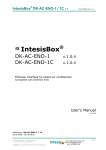
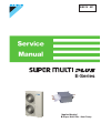
Outdoor Unit
Main Piping
Indoor Unit
BP Unit
Branch Piping
10
(Q0143)
Specifications
SiBE18-821
1.2
Specifications
BP Unit
50Hz 230V
Model
BPMKS967B2B
Connectable Indoor Units
BPMKS967B3B
1~2 Units
1~3 Units
Casing Color
Paintingless
Power Consumption
W
10
10
Running Current
Refrigerant Type
A
0.05
0.05
R-410A
Dimension (H×W×D)
Package Dimension (H×W×D)
mm
mm
180×294(650)*×350
257×738×427
Machine Weight
kg
7.5
8
Gross Weight
kg
11
12
mm
Main : φ9.5×1 / Branch : φ6.4×2
Main : φ9.5×1 / Branch : φ6.4×3
mm
Main : φ19.1×1 / Branch : φ15.9×2
Main : φ19.1×1 / Branch : φ15.9×3
Number of Wiring Connections
Liquid
Piping
Connection
Gas
(Brazing)
Drain
4 for Interunit Wiring
Heat Insulation
Max. Piping Length
Amount of Additional Charge
mm
Drain Processingless
m
Both Liquid and Gas Pipes
—
g/m
—
Max. Height Difference
m
Max. Combination
Min. Combination
kW
kW
Installation Manual
—
14.2
2.0
pc.
1
For Main
L Shape Reducer
pc.
Accessories
Liquid
1 (For I.D. φ6.4)
Gas
1 (For I.D. φ12.7)
1 (For I.D. φ15.9, 19.1)
Gas
For Branch
Hanger Metal
20.8
2.0
Gas
2 (For I.D. φ12.7, 9.5)
pc.
Screws
pc.
Heat Insulation (2pc. is 1 set)
Binding Band
pc.
Drawing No.
3 (For I.D. φ12.7, 9.5)
1 (For I.D. φ9.5)
Liquid
4
8 (M4×8)
3 Set
4 Set
2
C : 4D050058B
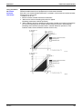
Note:
1. BP or Indoor Unit Max. Height - BP or Indoor Unit Min. Height → Max. 15m.
Set up BP and indoor unit within 15m height difference.
2. The piping connection must be cut so as to suit the piping sizes of the indoor unit which will be connected.
The same sizes should be used for the piping on the outdoor unit.
3. ( )* : including auxiliary piping length
Specifications
Conversion Formulae
kcal/h=kW×860
Btu/h=kW×3414
cfm=m³/min×35.3
11
Specifications
1.3
SiBE18-821
Indoor Units
Wall Mounted Type
50Hz 230V
FTXG25EV1BW
Model
Cooling
Rated Capacity
Front Panel Color
Airflow Rates
m³/min
(cfm)
Type
Motor Output
Speed
Air Direction Control
Air Filter
Running Current (Rated)
Power Consumption (Rated)
Power Factor
Temperature Control
Dimensions (H×W×D)
Packaged Dimensions (H×W×D)
Weight
Gross Weight
Operation
H/M/L/SL
Sound
Sound Power H
Heat Insulation
Liquid
Piping Connection
Gas
Drain
Drawing No.
H
M
L
SL
W
Steps
A
W
%
mm
mm
kg
kg
7.7 (271)
6.1 (215)
4.7 (165)
3.8 (134)
9.0 (317)
7.9 (278)
6.7 (236)
5.4 (190)
Cross Flow Fan
40
5 Steps, Quiet, Auto
Right, Left, Horizontal, Downward
Removable-Washable-Mildew Proof
0.15-0.14-0.13
0.15-0.14-0.13
30-30-30
30-30-30
90.9-93.2-96.2
90.9-93.2-96.2
Microcomputer Control
275×840×150
222×894×345
9
13
7.7 (271)
6.1 (215)
4.7 (165)
3.8 (134)
Cross Flow Fan
40
5 Steps, Quiet, Auto
Right, Left, Horizontal, Downward
Removable-Washable-Mildew Proof
0.15-0.14-0.13
0.15-0.14-0.13
30-30-30
30-30-30
90.9-93.2-96.2
90.9-93.2-96.2
Microcomputer Control
275×840×150
222×894×345
9
13
38/32/25/22
38/33/28/25
38/32/25/22
38/33/28/25
56
56
56
56
Both Liquid and Gas Pipes
φ 6.4
φ 9.5
φ18.0
3D051101
mm
mm
mm
Both Liquid and Gas Pipes
φ 6.4
φ 9.5
φ18.0
3D051102
FTXG35EV1BW
Rated Capacity
Front Panel Color
FTXG35EV1BS
Heating
Cooling
3.5kW Class
Mat Crystal White
Type
Motor Output
Speed
Air Direction Control
Air Filter
Running Current (Rated)
Power Consumption (Rated)
Power Factor
Temperature Control
Dimensions (H×W×D)
Packaged Dimensions (H×W×D)
Weight
Gross Weight
Operation
H/M/L/SL
Sound
Sound Power H
Heat Insulation
Liquid
Piping Connection
Gas
Drain
Drawing No.
9.0 (317)
7.9 (278)
6.7 (236)
5.4 (190)
dBA
Cooling
m³/min
(cfm)
Heating
2.5kW Class
Mat Crystal Silver
dBA
Model
Fan
Cooling
2.5kW Class
Mat Crystal White
Fan
Airflow Rates
FTXG25EV1BS
Heating
H
M
L
SL
W
Steps
A
W
%
mm
mm
kg
kg
8.1 (285)
6.5 (229)
4.9 (173)
4.1 (144)
Heating
5.0kW Class
Mat Crystal Silver
9.6 (338)
8.2 (289)
6.7 (236)
5.9 (208)
Cross Flow Fan
40
5 Steps, Quiet, Auto
Right, Left, Horizontal, Downward
Removable-Washable-Mildew Proof
0.15-0.14-0.13
0.15-0.14-0.13
30-30-30
30-30-30
90.9-93.2-96.2
90.9-93.2-96.2
Microcomputer Control
275×840×150
222×894×345
9
13
8.1 (285)
6.5 (229)
4.9 (173)
4.1 (144)
9.6 (338)
8.2 (289)
6.7 (236)
5.9 (208)
Cross Flow Fan
40
5 Steps, Quiet, Auto
Right, Left, Horizontal, Downward
Removable-Washable-Mildew Proof
0.15-0.14-0.13
0.15-0.14-0.13
30-30-30
30-30-30
90.9-93.2-96.2
90.9-93.2-96.2
Microcomputer Control
275×840×150
222×894×345
9
13
dBA
39/33/26/23
39/34/29/26
39/33/26/23
39/34/29/26
dBA
57
57
57
57
mm
mm
mm
Both Liquid and Gas Pipes
φ 6.4
φ 9.5
φ18.0
3D051103
Both Liquid and Gas Pipes
φ 6.4
φ12.7
φ18.0
3D051104
Conversion Formulae
kcal/h=kW×860
Btu/h=kW×3414
cfm=m³/min×35.3
12
Specifications
SiBE18-821
Specifications
50Hz 230V
CTXG50EV1BW
Model
Cooling
Rated Capacity
Front Panel Color
Airflow Rates
m³/min
(cfm)
Type
Motor Output
Speed
Air Direction Control
Air Filter
Running Current (Rated)
Power Consumption (Rated)
Power Factor
Temperature Control
Dimensions (H×W×D)
Packaged Dimensions (H×W×D)
Weight
Gross Weight
Operation
H/M/L/SL
Sound
Sound Power H
Heat Insulation
Liquid
Piping Connection
Gas
Drain
Drawing No.
H
M
L
SL
W
Steps
A
W
%
mm
mm
kg
kg
11.3 (398)
9.1 (320)
7.1 (250)
6.7 (236)
12.6 (444)
10.6 (373)
8.7 (306)
7.7 (271)
Cross Flow Fan
40
5 Steps, Quiet, Auto
Right, Left, Horizontal, Downward
Removable-Washable-Mildew Proof
0.15-0.14-0.13
0.15-0.14-0.13
30
30
90.9-93.2-96.2
90.9-93.2-96.2
Microcomputer Control
275×840×150
222×894×345
9
13
11.3 (398)
9.1 (320)
7.1 (250)
6.7 (236)
Cross Flow Fan
40
5 Steps, Quiet, Auto
Right, Left, Horizontal, Downward
Removable-Washable-Mildew Proof
0.15-0.14-0.13
0.15-0.14-0.13
30
30
90.9-93.2-96.2
90.9-93.2-96.2
Microcomputer Control
275×840×150
222×894×345
9
13
47/41/35/32
47/41/35/32
47/41/35/32
47/41/35/32
64
64
64
64
Both Liquid and Gas Pipes
φ 6.4
φ 12.7
φ18.0
3D051105
mm
mm
mm
Both Liquid and Gas Pipes
φ 6.4
φ 12.7
φ18.0
3D051106
FTXS20G2V1B
Rated Capacity
Front Panel Color
FTXS25G2V1B
Heating
Cooling
2.0kW Class
White
Type
Motor Output
Speed
Air Direction Control
Air Filter
Running Current (Rated)
Power Consumption (Rated)
Power Factor
Temperature Control
Dimensions (H×W×D)
Packaged Dimensions (H×W×D)
Weight
Gross Weight
Operation
H/M/L/SL
Sound
Sound Power H
Heat Insulation
Liquid
Piping Connection
Gas
Drain
Drawing No.
12.6 (444)
10.6 (373)
8.7 (306)
7.7 (271)
dBA
Cooling
m³/min
(cfm)
Heating
5.0kW Class
Mat Crystal Silver
dBA
Model
Fan
Cooling
5.0kW Class
Mat Crystal White
Fan
Airflow Rates
CTXG50EV1BS
Heating
H
M
L
SL
W
Steps
A
W
%
mm
mm
kg
kg
9.4 (332)
7.4 (262)
5.5 (193)
4.0 (141)
Heating
2.5kW Class
White
9.9 (350)
8.2 (290)
6.5 (228)
5.5 (193)
Cross Flow Fan
23
5 Steps, Quiet, Auto
Right, Left, Horizontal, Downward
Removable / Washable / Mildew Proof
0.08
0.10
18
21
97.8
91.3
Microcomputer Control
295×800×215
274×870×366
9
13
9.1 (321)
7.1 (252)
5.2 (182)
3.7 (130)
9.8 (346)
7.9 (280)
6.2 (217)
5.2 (183)
Cross Flow Fan
23
5 Steps, Quiet, Auto
Right, Left, Horizontal, Downward
Removable / Washable / Mildew Proof
0.08
0.10
18
21
97.8
91.3
Microcomputer Control
295×800×215
274×870×366
9
13
dBA
38/32/25/22
38/33/28/25
38/32/25/22
39/34/28/25
dBA
54
54
54
55
mm
mm
mm
Both Liquid and Gas Pipes
φ 6.4
φ 9.5
φ18.0
3D059722
Both Liquid and Gas Pipes
φ 6.4
φ 9.5
φ18.0
3D059723
Conversion Formulae
kcal/h=kW×860
Btu/h=kW×3414
cfm=m³/min×35.3
Specifications
13
Specifications
SiBE18-821
50Hz 230V
FTXS35G2V1B
Model
Cooling
Rated Capacity
Front Panel Color
Airflow Rates
m³/min
(cfm)
Type
Motor Output
Speed
Air Direction Control
Air Filter
Running Current (Rated)
Power Consumption (Rated)
Power Factor
Temperature Control
Dimensions (H×W×D)
Packaged Dimensions (H×W×D)
Weight
Gross Weight
Operation
H/M/L/SL
Sound
Sound Power H
Heat Insulation
Liquid
Piping Connection
Gas
Drain
Drawing No.
H
M
L
SL
W
Steps
A
W
%
mm
mm
kg
kg
10.7 (367)
7.7 (270)
4.8 (170)
3.5 (125)
Heating
4.2kW Class
White
10.6 (374)
8.5 (302)
6.4 (226)
5.4 (191)
9.1 (321)
7.7 (273)
6.3 (221)
5.4 (190)
Cross Flow Fan
23
5 Steps, Quiet, Auto
Right, Left, Horizontal, Downward
Removable / Washable / Mildew Proof
0.12
0.13
26
28
94.2
93.6
Microcomputer Control
295×800×215
274×870×366
10
13
11.2 (395)
9.4 (333)
7.7 (271)
6.8 (240)
Cross Flow Fan
23
5 Steps, Quiet, Auto
Right, Left, Horizontal, Downward
Removable / Washable / Mildew Proof
0.11
0.14
24
30
94.9
93.2
Microcomputer Control
295×800×215
274×870×366
10
13
dBA
45/34/26/23
42/36/29/26
45/38/33/30
42/38/33/30
dBA
58
58
58
58
mm
mm
mm
Both Liquid and Gas Pipes
φ 6.4
φ 9.5
φ18.0
3D059724
Both Liquid and Gas Pipes
φ 6.4
φ 9.5
φ18.0
3D059725
FTXS50G2V1B
Model
Cooling
Rated Capacity
Front Panel Color
Heating
5.0kW Class
White
m³/min
(cfm)
Type
Motor Output
Speed
Air Direction Control
Air Filter
Running Current (Rated)
Power Consumption (Rated)
Power Factor
Temperature Control
Dimensions (H×W×D)
Packaged Dimensions (H×W×D)
Weight
Gross Weight
Operation
H/M/L/SL
Sound
Sound Power H
Heat Insulation
Liquid
Piping Connection
Gas
Drain
Drawing No.
Fan
Cooling
3.5kW Class
White
Fan
Airflow Rates
FTXS42G2V1B
Heating
H
M
L
SL
10.2 (360)
8.6 (305)
7.0 (246)
6.0 (212)
Cross Flow Fan
23
5 Steps, Quiet, Auto
Right, Left, Horizontal, Downward
Removable / Washable / Mildew Proof
W
Steps
A
W
%
0.12
26
94.2
0.14
32
99.4
Microcomputer Control
295×800×215
274×870×366
9
12
mm
mm
kg
kg
dBA
43/39/34/31
dBA
59
mm
mm
mm
11.0 (388)
9.3 (330)
7.6 (267)
6.7 (236)
44/39/34/31
60
Both Liquid and Gas Pipes
φ 6.4
φ 9.5
φ18.0
3D059726
Conversion Formulae
kcal/h=kW×860
Btu/h=kW×3414
cfm=m³/min×35.3
14
Specifications
SiBE18-821
Specifications
50Hz 230V
FTXS60FV1B
Model
Cooling
Rated Capacity
Front Panel Color
Airflow Rates
Cooling
6.0kW Class
White
m³/min
(cfm)
Type
Motor Output
Speed
Air Direction Control
Air Filter
Running Current (Rated)
Power Consumption (Rated)
Power Factor
Temperature Control
Dimensions (H×W×D)
Packaged Dimensions (H×W×D)
Weight
Gross Weight
Operation
H/M/L/SL
Sound
Sound Power H
Heat Insulation
Liquid
Piping Connection
Gas
Drain
Drawing No.
Fan
FTXS71FV1B
Heating
H
M
L
SL
W
Steps
A
W
%
mm
mm
kg
kg
16.2 (572)
13.6 (480)
11.4 (403)
10.2 (360)
Heating
7.1kW Class
White
17.4 (614)
15.1 (533)
12.7 (448)
11.4 (403)
Cross Flow Fan
43
5 Steps, Quiet, Auto
Right, Left, Horizontal, Downward
Removable-Washable-Mildew Proof
0.18
0.20
40
45
96.6
97.8
Microcomputer Control
290×1,050×238
337×1,147×366
12
17
17.4 (614)
14.6 (516)
11.6 (410)
10.6 (374)
19.7 (696)
16.9 (597)
14.3 (505)
12.7 (448)
Cross Flow Fan
43
5 Steps, Quiet, Auto
Right, Left, Horizontal, Downward
Removable-Washable-Mildew Proof
0.20
0.27
45
60
97.8
96.6
Microcomputer Control
290×1,050×238
337×1,147×366
12
17
dBA
45/41/36/33
44/40/35/32
46/42/37/34
46/42/37/34
dBA
61
60
62
62
mm
mm
mm
Both Liquid and Gas Pipes
φ 6.4
φ12.7
φ18.0
3D056020
Both Liquid and Gas Pipes
φ 6.4
φ15.9
φ18.0
3D056021A
Conversion Formulae
kcal/h=kW×860
Btu/h=kW×3414
cfm=m³/min×35.3
Specifications
15
Specifications
SiBE18-821
Duct Connected Type
50Hz 230V
FDXS50CVMB
Model
Cooling
Rated Capacity
Front Panel Color
m³/min
(cfm)
Type
Motor Output
Speed
H
M
L
SL
W
Steps
A
W
%
mm
mm
kg
kg
dBA
Pa
mm
mm
mm
12.0 (424)
11.0 (388)
10.0 (353)
8.4 (297)
—
12.0 (424)
11.0 (388)
10.0 (353)
8.4 (297)
Sirocco Fan
130
5 Steps, Quiet, Auto
Removable-Washable-Mildew Proof
0.64
0.64
140
140
95.1
95.1
Microcomputer Control
200×900×620
266×1,106×751
27
34
37/35/33/31
37/35/33/31
40
Both Liquid and Gas Pipes
φ 6.4
φ12.7
VP20 (O.D. φ 26 / I.D. φ 20)
3D052132
16.0 (565)
14.8 (523)
13.5 (477)
11.2 (395)
Cooling
Rated Capacity
Front Panel Color
16.0 (565)
14.8 (523)
13.5 (477)
11.2 (395)
Sirocco Fan
130
5 Steps, Quiet, Auto
Removable-Washable-Mildew Proof
0.74
0.74
160
160
94.0
94.0
Microcomputer Control
200×1,100×620
266×1,306×751
30
37
38/36/34/32
38/36/34/32
40
Both Liquid and Gas Pipes
φ 6.4
φ12.7
VP20 (O.D. φ 26 / I.D. φ 20)
3D052133
FDXS25EAVMB
Model
FDXS35EAVMB
Heating
Cooling
2.5kW Class
m³/min
(cfm)
Type
Motor Output
Speed
W
Steps
Air Filter
Running Current (Rated)
Power Consumption (Rated)
Power Factor
Temperature Control
Dimensions (H×W×D)
Packaged Dimensions (H×W×D)
Weight
Gross Weight
Operation
H/M/L/SL
Sound
External Static Pressure
Heat Insulation
Liquid
Piping Connection
Gas
Drain
Drawing No.
Note:
H
M
L
SL
A
W
%
mm
mm
kg
kg
dBA
Pa
mm
mm
mm
8.7 (307)
8.0 (282)
7.3 (258)
6.2 (219)
—
8.7 (307)
8.0 (282)
7.3 (258)
6.2 (219)
Sirocco Fan
62
5 Steps, Quiet, Auto
Removable-Washable-Mildew Proof
0.48
0.48
71
71
64.3
64.3
Microcomputer Control
200×700×620
274×906×751
21
29
35/33/31/29
Heating
3.5kW Class
—
Airflow Rates
16
Heating
6.0kW Class
—
Air Filter
Running Current (Rated)
Power Consumption (Rated)
Power Factor
Temperature Control
Dimensions (H×W×D)
Packaged Dimensions (H×W×D)
Weight
Gross Weight
Operation
H/M/L/SL
Sound
External Static Pressure
Heat Insulation
Liquid
Piping Connection
Gas
Drain
Drawing No.
Fan
Cooling
5.0kW Class
Airflow Rates
Fan
FDXS60CVMB
Heating
35/33/31/29
30
Both Liquid and Gas Pipes
φ 6.4
φ 9.5
VP20 (O.D. φ 26 / I.D. φ 20)
3D051881A
8.7 (307)
8.0 (282)
7.3 (258)
6.2 (219)
8.7 (307)
8.0 (282)
7.3 (258)
6.2 (219)
Sirocco Fan
62
5 Steps, Quiet, Auto
Removable-Washable-Mildew Proof
0.48
0.48
71
71
64.3
64.3
Microcomputer Control
200×700×620
274×906×751
21
29
35/33/31/29
35/33/31/29
30
Both Liquid and Gas Pipes
φ 6.4
φ 9.5
VP20 (O.D. φ 26 / I.D. φ 20)
3D051883A
1. The operating sound is based on the rear side suction inlet and the external static pressure 30 Pa.
Operating sound for under side suction inlet : [operating sound for rear side suction inlet] +6 dB.
However, when installation to which the external static pressure becomes low is carried out,
6 dB or more may go up.
Conversion Formulae
kcal/h=kW×860
Btu/h=kW×3414
cfm=m³/min×35.3
Specifications
SiBE18-821
Specifications
Floor / Ceiling Suspended Dual Type
50Hz 230V
FLXS25BAVMB
Model
Cooling
Rated Capacity
Front Panel Color
Airflow Rates
m³/min
(cfm)
Type
Motor Output
Speed
Air Direction Control
Air Filter
Running Current (Rated)
Power Consumption (Rated)
Power Factor
Temperature Control
Dimensions (H×W×D)
Packaged Dimensions (H×W×D)
Weight
Gross Weight
Operation
H/M/L/SL
Sound
Sound Power H
Heat Insulation
Liquid
Piping Connection
Gas
Drain
Drawing No.
H
M
L
SL
W
Steps
A
W
%
mm
mm
kg
kg
7.6 (268)
6.8 (240)
6.0 (212)
5.2 (184)
9.2 (325)
8.3 (293)
7.4 (261)
6.6 (233)
Sirocco Fan
34
5 Steps, Quiet, Auto
Right, Left, Horizontal, Downward
Removable-Washable-Mildew Proof
0.32
0.34
70
74
95.1
94.6
Microcomputer Control
490×1,050×200
566×1,100×280
16
22
8.6 (304)
7.6 (268)
6.6 (233)
5.6 (198)
Sirocco Fan
34
5 Steps, Quiet, Auto
Right, Left, Horizontal, Downward
Removable-Washable-Mildew Proof
0.36
0.36
78
78
94.2
94.2
Microcomputer Control
490×1,050×200
566×1,100×280
16
22
37/34/31/28
37/34/31/29
38/35/32/29
39/36/33/30
53
—
54
—
Both Liquid and Gas Pipes
φ 6.4
φ 9.5
φ18.0
3D050866
mm
mm
mm
Both Liquid and Gas Pipes
φ 6.4
φ 9.5
φ18.0
3D050868
FLXS50BAVMB
Rated Capacity
Front Panel Color
FLXS60BAVMB
Heating
Cooling
5.0kW Class
Almond White
Type
Motor Output
Speed
Air Direction Control
Air Filter
Running Current (Rated)
Power Consumption (Rated)
Power Factor
Temperature Control
Dimensions (H×W×D)
Packaged Dimensions (H×W×D)
Weight
Gross Weight
Operation
H/M/L/SL
Sound
Sound Power H
Heat Insulation
Liquid
Piping Connection
Gas
Drain
Drawing No.
9.8 (346)
8.9 (314)
8.0 (282)
7.2 (254)
dBA
Cooling
m³/min
(cfm)
Heating
3.5kW Class
Almond White
dBA
Model
Fan
Cooling
2.5kW Class
Almond White
Fan
Airflow Rates
FLXS35BAVMB
Heating
H
M
L
SL
W
Steps
A
W
%
mm
mm
kg
kg
11.4 (402)
10.0 (353)
8.5 (300)
7.5 (265)
Heating
6.0kW Class
Almond White
12.1 (427)
9.8 (346)
7.5 (265)
6.8 (240)
Sirocco Fan
34
5 Steps, Quiet, Auto
Right, Left, Horizontal, Downward
Removable-Washable-Mildew Proof
0.45
0.45
96
96
92.8
92.8
Microcomputer Control
490×1,050×200
280×1,100×566
17
24
12.0 (424)
10.7 (378)
9.3 (328)
8.3 (293)
12.8 (452)
10.6 (374)
8.4 (297)
7.5 (265)
Sirocco Fan
34
5 Steps, Quiet, Auto
Right, Left, Horizontal, Downward
Removable-Washable-Mildew Proof
0.47
0.45
98
96
90.7
92.8
Microcomputer Control
490×1,050×200
280×1,100×566
17
24
dBA
47/43/39/36
46/41/35/33
48/45/41/39
47/42/37/34
dBA
63
32
64
63
mm
mm
mm
Both Liquid and Gas Pipes
φ 6.4
φ12.7
φ18.0
3D050897
Both Liquid and Gas Pipes
φ 6.4
φ12.7
φ18.0
3D050882
Conversion Formulae
kcal/h=kW×860
Btu/h=kW×3414
cfm=m³/min×35.3
Specifications
17
Specifications
SiBE18-821
Floor Standing Type
50Hz 230V
FVXS25FV1B
Model
Cooling
Rated Capacity
Front Panel Color
Airflow Rates
Heating
Type
Motor Output
Speed
Air Direction Control
Air Filter
Running Current (Rated)
Power Consumption (Rated)
Power Factor
Temperature Control
Dimensions (H×W×D)
Packaged Dimensions (H×W×D)
Weight
Gross Weight
Operation
H/M/L/SL
Sound
Sound Power H
Heat Insulation
Liquid
Piping Connection
Gas
Drain
Drawing No.
Fan
H
M
L
SL
W
Steps
A
W
%
8.2 (290)
6.5 (229)
4.8 (169)
4.1 (146)
Heating
3.5kW Class
White
8.8 (311)
6.9 (244)
5.0 (178)
4.4 (155)
8.5 (300)
6.7 (237)
4.9 (174)
4.5 (158)
Turbo Fan
48
5 Steps, Quiet, Auto
Right, Left, Horizontal, Downward
Removable-Washable-Mildew Proof
0.13
0.14
15
17
50.2
52.8
Microcomputer Control
600×700×210
696×786×286
14
18
9.4 (332)
7.3 (258)
5.2 (184)
4.7 (168)
Turbo Fan
48
5 Steps, Quiet, Auto
Right, Left, Horizontal, Downward
Removable-Washable-Mildew Proof
0.13
0.14
15
17
50.2
52.8
Microcomputer Control
600×700×210
696×786×286
14
18
mm
mm
kg
kg
dBA
38/32/26/23
38/32/26/23
39/33/27/24
39/33/27/24
dBA
54
54
55
55
mm
mm
mm
Both Liquid and Gas Pipes
φ 6.4
φ 9.5
φ 20.0
3D056274A
Both Liquid and Gas Pipes
φ 6.4
φ 9.5
φ 20.0
3D056275A
FVXS50FV1B
Model
Cooling
Rated Capacity
Front Panel Color
Heating
5.0kW Class
White
m³/min
(cfm)
Type
Motor Output
Speed
Air Direction Control
Air Filter
Running Current (Rated)
Power Consumption (Rated)
Power Factor
Temperature Control
Dimensions (H×W×D)
Packaged Dimensions (H×W×D)
Weight
Gross Weight
Operation
H/M/L/SL
Sound
Sound Power H
Heat Insulation
Liquid
Piping Connection
Gas
Drain
Drawing No.
Fan
Cooling
2.5kW Class
White
m³/min
(cfm)
Airflow Rates
FVXS35FV1B
H
M
L
SL
10.7 (378)
9.2 (326)
7.8 (274)
6.6 (233)
Turbo Fan
48
5 Steps, Quiet, Auto
Right, Left, Horizontal, Downward
Removable-Washable-Mildew Proof
W
Steps
A
W
%
0.17
27
69.1
0.19
34
77.8
Microcomputer Control
600×700×210
696×786×286
14
18
mm
mm
kg
kg
dBA
44/40/36/32
dBA
56
mm
mm
mm
11.8 (417)
10.1 (358)
8.5 (300)
7.1 (250)
45/40/36/32
57
Both Liquid and Gas Pipes
φ 6.4
φ12.7
φ20.0
3D056276
Conversion Formulae
kcal/h=kW×860
Btu/h=kW×3414
cfm=m³/min×35.3
18
Specifications
SiBE18-821
Specifications
Ceiling Mounted Cassette Type
50Hz 230V
FFQ25B8V1B
Model
Cooling
Rated Capacity
Color
Decoration
Panel
Dimensions (H×W×D)
Airflow Rates
m³/min
(cfm)
Type
Fan
Motor Output
Speed
Air Direction Control
Air Filter
Cooling
2.5kW Class
White
55×700×700
H
M
L
SL
9.0 (318)
10.0 (353)
—
—
—
—
6.5 (230)
6.5 (230)
6.5 (230)
6.5 (230)
—
—
—
—
Turbo Fan
55
2 Steps
Horizontal, Downward
dBA
dBA
mm
mm
mm
—
0.37
73
85.8
0.32
64
87.0
0.40
84
91.3
Microcomputer Control
260(286)×575×575
370×687×674
17.5
21
mm
mm
kg
kg
29.5/24.5
0.36
76
91.8
Microcomputer Control
260(286)×575×575
370×687×674
17.5
21
29.5/24.5
46.5
—
Both Liquid and Gas Pipes
φ 6.4
φ 9.5
VP20 (O.D φ 26 / I.D φ 20)
3D040445
32.0/25.0
Cooling
Rated Capacity
Color
Decoration
Panel
Dimensions (H×W×D)
m³/min
(cfm)
Type
Fan
Motor Output
Speed
Air Direction Control
Air Filter
FFQ60B8V1B
Heating
Cooling
5.0kW Class
White
55×700×700
H
M
L
SL
12.0 (424)
15.0 (530)
—
—
—
—
8.0 (283)
8.0 (283)
10.0 (353)
10.0 (353)
—
—
—
—
Turbo Fan
55
2 Steps
Horizontal, Downward
★
mm
mm
kg
kg
dBA
dBA
mm
mm
mm
—
0.49
97
86.1
0.45
89
86.0
Microcomputer Control
260(286)×575×575
370×687×674
17.5
21
36.0/27.0
36.0/27.0
53.0
—
Both Liquid and Gas Pipes
φ 6.4
φ 12.7
VP20 (O.D φ 26 / I.D φ 20)
3D040441
( ) : dimension including control box
15.0 (530)
Turbo Fan
55
2 Steps
Horizontal, Downward
—
A
W
%
Heating
6.0kW Class
White
55×700×700
12.0 (424)
W
Steps
Running Current (Rated)
Power Consumption (Rated)
Power Factor
Temperature Control
Dimensions (H×W×D) ★
Packaged Dimensions (H×W×D)
Weight
Gross Weight
Operation
H/L
Sound
Sound Power H
Heat Insulation
Liquid
Piping Connection
Gas
Drain
Drawing No.
32.0/25.0
49.0
—
Both Liquid and Gas Pipes
φ 6.4
φ 9.5
VP20 (O.D φ 26 / I.D φ 20)
3D040443
FFQ50B8V1B
Model
10.0 (353)
Turbo Fan
55
2 Steps
Horizontal, Downward
—
A
W
%
Heating
3.5kW Class
White
55×700×700
9.0 (318)
W
Steps
Running Current (Rated)
Power Consumption (Rated)
Power Factor
Temperature Control
Dimensions (H×W×D) ★
Packaged Dimensions (H×W×D)
Weight
Gross Weight
Operation
H/L
Sound
Sound Power H
Heat Insulation
Liquid
Piping Connection
Gas
Drain
Drawing No.
Airflow Rates
FFQ35B8V1B
Heating
0.61
120
85.5
0.56
111
86.2
Microcomputer Control
260(286)×575×575
370×687×674
17.5
21
41.0/32.0
41.0/32.0
58.0
—
Both Liquid and Gas Pipes
φ 6.4
φ 12.7
VP20 (O.D φ 26 / I.D φ 20)
3D040436
Conversion Formulae
kcal/h=kW×860
Btu/h=kW×3414
cfm=m³/min×35.3
Specifications
19
Specifications
SiBE18-821
Ceiling-suspended Type
50Hz 230V
Model
Rated Capacity
Color
Decoration
Panel
Dimensions (H×W×D)
Airflow Rates
m³/min
(cfm)
Type
Motor Output
Speed
Air Direction Control
Air Filter
Temperature Control
Dimensions (H×W×D)
Packaged Dimensions (H×W×D)
Weight
Gross Weight
Operation
H/L
Sound
Sound Power H/L
Heat Insulation
Liquid
Piping Connection
Gas
Drain
Drawing No.
Fan
H
M
L
SL
W
Steps
mm
mm
kg
kg
FHQ35BVV1B
Cooling
Heating
3.5kW Class
White
—
13.0 (458)
13.0 (458)
—
10.0 (353)
10.0 (353)
—
Sirocco Fan
62
2 Steps
Right, Left, Horizontal, Downward
Removable-Washable-Mildew Proof
Microcomputer Control
195×960×680
279×1,046×818
24
31
FHQ50BVV1B
Cooling
Heating
5.0kW Class
White
—
13.0 (458)
13.0 (458)
—
10.0 (353)
10.0 (353)
—
Sirocco Fan
62
2 Steps
Right, Left, Horizontal, Downward
Removable-Washable-Mildew Proof
Microcomputer Control
195×960×680
279×1,046×818
25
32
FHQ60BVV1B
Cooling
Heating
6.0kW Class
White
—
17.0 (600)
16.0 (565)
—
13.0 (459)
13.0 (459)
—
Sirocco Fan
62
2 Steps
Right, Left, Horizontal, Downward
Removable-Washable-Mildew Proof
Microcomputer Control
195×1,160×680
279×1,246×818
27
35
dBA
37/32
38/33
39/33
dBA
53/48
Both Liquid and Gas Pipes
φ 6.4 (Flare)
φ 9.5 (Flare)
VP20 (O.D.φ 26 / I.D.φ 20)
3D037992E
54/49
Both Liquid and Gas Pipes
φ 6.4 (Flare)
φ12.7 (Flare)
VP20 (O.D.φ 26 / I.D.φ 20)
3D037992E
55/49
Both Liquid and Gas Pipes
φ 6.4 (Flare)
φ12.7 (Flare)
VP20 (O.D.φ 26 / I.D.φ 20)
3D037992E
mm
mm
mm
Conversion Formulae
kcal/h=kW×860
Btu/h=kW×3414
cfm=m³/min×35.3
20
Specifications
SiBE18-821
Part 3
Printed Circuit Board
Connector Wiring Diagram
1. Printed Circuit Board Connector Wiring Diagram ............................................22
1.1
1.2
1.3
1.4
1.5
1.6
1.7
1.8
1.9
1.10
Outdoor Unit RMXS 112/140/160 E8V1B ..............................................22
Branch Provider Unit ..............................................................................27
FTXG25~35E, CTXG50E .......................................................................28
Wall Mounted Type 20-50 Class - G Series ...........................................30
Wall Mounted Type 60/71 Class - F Series............................................32
Duct Connected Type.............................................................................34
Floor / Ceiling Suspended Dual Type.....................................................36
Floor Standing Type ...............................................................................39
Ceiling Mounted Cassette 600×600 Type ..............................................42
Ceiling Suspended Type ........................................................................44
Printed Circuit Board Connector Wiring Diagram
21
Printed Circuit Board Connector Wiring Diagram
SiBE18-821
1. Printed Circuit Board Connector Wiring Diagram
1.1
Outdoor Unit RMXS 112/140/160 E8V1B
1.1.1 Main PCB (A1P)
Connectors
1) X5A
2) X11A
3) X12A
Connector to Service PCB (A2P)
Connector for Outdoor Air Thermistor
Connector for Thermistors
(Suction Pipe1, 2, Heat Exchanger, Discharge Pipe)
4) X13A
Connector for Thermistors (Subcool Outlet, Liquid Pipe)
5) X17A
Connector for High Pressure Sensor
6) X18A
Connector for Low Pressure Sensor
7) X21A
Connector for Electronic Expansion Valve (Main)
8) X22A
Connector for Electronic Expansion Valve (Sub Cool)
9) X25A
Connector for Y1S (Four Way Valve)
10) X26A
Connector for Y2S (Hot Gas Bypass Valve)
11) X27A
Connector for Y3S (Unload)
12) X28A
Connector for Crankcase Heater
13) X32A
Connector for High Pressure Switch
14) X37A
Connector for Power Supply for Optional PCB (DC16V)
15) X66A
Connector for C/H Selector PCB (A4P)
16) X81A
Connector for Terminal Strip
17) X106A, X107A Connector for Fan Motor (Upper, lower)
18) X111A
Connector for Fin Thermistor
19) LD, LE
Connector for Reactor
20) LC, NC
Connector for Noise Filter PCB (A3P)
21) P
Connector for Capacitor C4 +
22) N
Connector for Capacitor C4 –
23) U, V, W
Connector for Compressor
Note:
22
Other Designation
1) F4U
Fuse (6.3A / 250V)
2) F6U
Fuse (5.0A / 250V)
3) HAP
Operation Pilot Lamp
Printed Circuit Board Connector Wiring Diagram
SiBE18-821
PCB Detail
Printed Circuit Board Connector Wiring Diagram
Main PCB (A1P)
X106A
X107A
F6U
P
X111A
X66A
N
X37A
X81A
X5A
X22A
LE
X21A
X13A
X11A
X12A
NC
X18A
X17A
X32A
LC
HAP
X25A
X26A
X27A
X28A
LD
F4U
2P210453
Printed Circuit Board Connector Wiring Diagram
23
Printed Circuit Board Connector Wiring Diagram
SiBE18-821
1.1.2 Service PCB (A2P)
Connectors
1) X205A
Note:
PCB Detail
Connector for Main PCB (A1P)
Other Designation
1) H1P to H8P Service Monitor LED
2) BS1 to BS5 Push Button Switch (Mode, Set, Return, Test, Reset)
3) DS1
DIP Switch
Service PCB (A2P)
DS1
H8P
BS5
H7P
BS4
H6P
H5P
BS3
H4P
BS2
H3P
H2P
BS1
H1P
X205A
4P210454
24
Printed Circuit Board Connector Wiring Diagram
SiBE18-821
Printed Circuit Board Connector Wiring Diagram
1.1.3 Noise Filter PCB (A3P)
Connectors
1) LA, NA
2) LB, NB
3) E
Note:
PCB Detail
Terminal for X1M (Power Supply)
Terminal for Main PCB (A1P)
Terminal for Earth
Other Designation
1) F1U
Fuse (250V 6.3A)
Noise Filter PCB (A3P)
F1U
NB
NA
LA
LB
E
Printed Circuit Board Connector Wiring Diagram
3P210455
25
Printed Circuit Board Connector Wiring Diagram
SiBE18-821
1.1.4 Cool / Heat Selector PCB (A4P)
Connectors
1) X1A
Note:
PCB Detail
Connector for Main PCB (A1P)
Other Designation
1) X1M
Cool / Heat Selector
Cool / Heat Selector PCB (A4P)
X1A
X1M
3P175810
26
Printed Circuit Board Connector Wiring Diagram
SiBE18-821
1.2
Printed Circuit Board Connector Wiring Diagram
Branch Provider Unit
Connectors
1) X20A
2) X21A to X23A
3) X90A
Note:
Connector for Bypass Electronic Expansion Valve
Connector for Electronic Expansion Valve to Room A, B and C
Connector for Thermistors
Other Designations
1) F2U
2) X3M
3) X4M
4) X5M
5) F1, F2 (on X6M)
6) L1, N1 (on X1M)
7) L2, N2 (on X1M)
8) H1P(LED-A)
9) H2P~H5P (LED 1 to 4)
Fuse (AC250V 3.15A)
Terminal for Inter Connecting Wire to Room A
Terminal for Inter Connecting Wire to Room B
Terminal for Inter Connecting Wire to Room C
Terminal for Transmission to Outdoor Unit or Other BP units
Terminal for Power Supply (230V 50Hz)
Terminal for Power Supply to other BP units
LED for Service Monitor
LED for Fault Indication
X23A and X5M are not used for BPMKS967B2B.
PCB Detail
BP Unit PCB
X90A
X23A
X22A
X3M
X21A
H1P (LED A)
H2P (LED 1)
H3P (LED 2)
H4P (LED 3)
H5P (LED 4)
X4M
X20A
F2
X6M
F1
N2
N2
L2
X5M
L2
N1
X1M
L1
N1
L1
F2U
3P152439
Printed Circuit Board Connector Wiring Diagram
27
Printed Circuit Board Connector Wiring Diagram
1.3
SiBE18-821
FTXG25~35E, CTXG50E
Connectors
PCB(1) (Control PCB)
1)
2)
3)
4)
S1
S21
S32
S36
5)
6)
7)
8)
S41
S46
S49
S51
Connector for fan motor
Connector for centralized control (HA)
Connector for heat exchanger thermistor
Connector for INTELLIGENT EYE sensor PCB and control
PCB
Connector for swing motor
Connector for signal receiver PCB
Connector for reduction motor (front panel mechanism)
Connector for front panel limit switch
PCB(2) (Signal Receiver PCB)
1) S47
Connector for control PCB
PCB(3) (INTELLIGENT EYE sensor PCB)
1) S36
Note:
Connector for control PCB
Other designations
PCB(1) (Control PCB)
1) V1
2) JA
JB
JC
3) FU1
4) LED A
Varistor
Address setting jumper
Fan speed setting when compressor is OFF on thermostat
Power failure recovery function (auto-restart)
∗ Refer to page 168 for detail.
Fuse (3.15A)
LED for service monitor (green)
PCB(2) (Signal Receiver PCB)
1)
2)
3)
4)
5)
28
SW1
LED2
LED3
LED4
RTH1
Forced operation ON / OFF switch
LED for INTELLIGENT EYE (green)
LED for timer (yellow)
LED for operation (green)
Room temperature thermistor
Printed Circuit Board Connector Wiring Diagram
SiBE18-821
PCB Detail
Printed Circuit Board Connector Wiring Diagram
PCB(1): Control PCB (indoor unit)
S1
S49
S41
S51
JB
JA JC
LED A
V1
S21
FU1
S46
S36
S32
(R4991)
PCB(2): Signal Receiver PCB
S47
RTH1
SW1
LED4
LED2
LED3
(R4992)
PCB(3): INTELLIGENT EYE sensor PCB
S36
(R4988)
Printed Circuit Board Connector Wiring Diagram
29
Printed Circuit Board Connector Wiring Diagram
1.4
SiBE18-821
Wall Mounted Type 20-50 Class - G Series
Connectors
PCB(1) (Control PCB)
1)
2)
3)
4)
5)
6)
7)
S1
S21
S25
S32
S41
S46
S47
Connector for DC fan motor
Connector for centralized control (HA)
Connector for INTELLIGENT EYE sensor PCB
Connector for heat exchanger thermistor
Connector for swing motor
Connector for display PCB
Connector for signal receiver PCB
PCB(2) (Signal Receiver PCB)
1) S48
Connector for control PCB
PCB(3) (Display PCB)
1) S49
Connector for control PCB
PCB(4) (INTELLIGENT EYE sensor PCB)
1) S26
Note:
Connector for control PCB
Other designations
PCB(1) (Control PCB)
1) V1
2) JA
JB
JC
3) LED A
4) FU1
Varistor
Address setting jumper
Fan speed setting when compressor is OFF on thermostat
Power failure recovery function (auto-restart)
∗ Refer to page 168 for detail.
LED for service monitor (green)
Fuse (3.15A)
PCB(3) (Display PCB)
1)
2)
3)
4)
5)
30
SW1 (S1W)
LED1
LED2
LED3
RTH1 (R1T)
Forced operation ON / OFF switch
LED for operation (green)
LED for timer (yellow)
LED for INTELLIGENT EYE (green)
Room temperature thermistor
Printed Circuit Board Connector Wiring Diagram
SiBE18-821
PCB Detail
S41
Printed Circuit Board Connector Wiring Diagram
PCB(1): Control PCB
S1
S32
LED A
FU1
S46
V1
S25
S47 JC JB S21
JA
2P206687
PCB(2): Signal Receiver PCB
PCB(3): Display PCB
RTH1
SW1
LED3
LED2
LED1
S48
(R8246)
S49
(R8247)
PCB(4): INTELLIGENT EYE sensor PCB
S26
3EB86013
Printed Circuit Board Connector Wiring Diagram
31
Printed Circuit Board Connector Wiring Diagram
1.5
SiBE18-821
Wall Mounted Type 60/71 Class - F Series
Connectors
PCB(1) (Control PCB)
1)
2)
3)
4)
5)
6)
7)
8)
S1
S6
S8
S21
S26
S28
S32
S35
Connector for DC fan motor
Connector for swing motor (horizontal blades)
Connector for swing motor (vertical blades)
Connector for centralized control (HA)
Connector for buzzer PCB
Connector for signal receiver PCB
Connector for heat exchanger thermistor
Connector for Intelligent Eye sensor PCB
PCB(2) (Signal Receiver PCB)
1) S29
Connector for control PCB
PCB(3) (Buzzer PCB)
1) S27
2) S38
Connector for control PCB
Connector for display PCB
PCB(4) (Display PCB)
1) S37
Connector for buzzer PCB
PCB(5) (INTELLIGENT EYE sensor PCB)
1) S36
Note:
Connector for control PCB
Other designations
PCB(1) (Control PCB)
1) V1
2) JA
JB
JC
3) LED A
4) FU1
Varistor
Address setting jumper
Fan speed setting when compressor is OFF on thermostat
Power failure recovery function
∗ Refer to page 168 for detail.
LED A for service monitor (green)
Fuse (3.15A)
PCB(2) (Signal Receiver PCB)
1) SW1 (S1W)
Forced operation ON/OFF switch
PCB(3) (Buzzer PCB)
1) RTH1 (R1T)
Room temperature thermistor
PCB(4) (Display PCB)
4) LED1
5) LED2
6) LED3
32
LED for operation (green)
LED for timer (yellow)
LED for HOME LEAVE operation (red)
Printed Circuit Board Connector Wiring Diagram
SiBE18-821
PCB Detail
Printed Circuit Board Connector Wiring Diagram
PCB(1): Control PCB (indoor unit)
S1
V1
FU1
S21
S6
S8
S35
LED A
JA
JB JC
PCB(2): Signal Receiver PCB
S32 S28
S26
(R2860)
PCB(3): Buzzer PCB
S27
SW1
S38
S29
(R2861)
RTH1
PCB(4): Display PCB
LED1
LED2
(R2862)
PCB(5): INTELLIGENT EYE sensor PCB
LED3
S37
(R2863)
S36
(R2864)
Printed Circuit Board Connector Wiring Diagram
33
Printed Circuit Board Connector Wiring Diagram
1.6
SiBE18-821
Duct Connected Type
Connectors
PCB(1) (Control PCB)
1)
2)
3)
4)
5)
S1
S7
S21
S26
S32
Connector for AC fan motor
Connector for AC fan motor
Connector for centralized control to 5 rooms
Connector for display PCB
Connector for heat exchanger thermistor
PCB(2) (Display PCB)
1) S1
Note:
Connector for control PCB
Other designations
PCB(1) (Control PCB)
1) V1
2) JA
JB
JC
3) LED A
4) FU1
Varistor
Address setting jumper
Fan speed setting when compressor is OFF on thermostat
Power failure recovery function
∗ Refer to page 168 for more detail.
LED for service monitor (green)
Fuse (3.15A)
PCB(2) (Display PCB)
1)
2)
3)
4)
5)
PCB Detail
SW1 (S1W)
LED1
LED2
LED3
RTH1 (R1T)
Forced operation ON/OFF switch
LED for operation (green)
LED for timer (yellow)
LED for HOME LEAVE operation (red)
Room temperature thermistor
PCB (1): Control PCB (indoor unit)
FU1
S1
V1
S7
S21
S26
LED A JA
34
JB JC
S32
2P131149
Printed Circuit Board Connector Wiring Diagram
SiBE18-821
PCB Detail
Printed Circuit Board Connector Wiring Diagram
PCB (2): Display PCB
S1
LED3
WLU
PbF
LED2
RTH1
C3
C2
+
C1
Pb Free
SW1
LED1
2P084375
Printed Circuit Board Connector Wiring Diagram
35
Printed Circuit Board Connector Wiring Diagram
1.7
SiBE18-821
Floor / Ceiling Suspended Dual Type
Connectors
PCB(1) (Control PCB)
1)
2)
3)
4)
5)
6)
7)
S6
S7
S21
S24
S26
S32
S37
Connector for swing motor (horizontal swing)
Connector for AC fan motor
Connector for centralized control
Connector for display PCB
Connector for signal receiver PCB
Connector for heat exchanger thermistor
Connector for power supply PCB
PCB(2) (Power Supply PCB)
1) S36
Connector for control PCB
PCB(3) (Display PCB)
1) S25
Connector for control PCB
PCB(4) (Signal Receiver PCB)
1) S27
2) S31
Note:
Connector for control PCB
Connector for room temperature thermistor
Other designations
PCB(1) (Control PCB)
1) JA
JB
JC
2) SW2
3) LED A
Address setting jumper
Fan speed setting when compressor is OFF on thermostat
Power failure recovery function
∗ Refer to page 168 for detail.
Select switch ceiling or floor
LED for service monitor (green)
PCB(2) (Power Supply PCB)
1) V1
1) FU1
Varistor
Fuse (3.15A)
PCB(3) (Display PCB)
1) LED1
2) LED2
3) LED3
LED for operation (green)
LED for timer (yellow)
LED for HOME LEAVE operation (red)
PCB(4) (Signal Receiver PCB)
1) SW1 (S1W)
36
Forced operation ON/OFF switch
Printed Circuit Board Connector Wiring Diagram
SiBE18-821
Printed Circuit Board Connector Wiring Diagram
PCB Detail
PCB (1): Control PCB (indoor unit)
PCB Detail
PCB (2): Power Supply PCB
Printed Circuit Board Connector Wiring Diagram
37
Printed Circuit Board Connector Wiring Diagram
SiBE18-821
PCB (3): Display PCB
PCB (4): Signal Receiver PCB
SW1
EX511 REV 12
PbF
S27
C1
3
SW1 C2
RTH
I
PHOTO
2P084377- 1
S31(RTH)
38
WLU C3
(R4977)
Printed Circuit Board Connector Wiring Diagram
SiBE18-821
1.8
Printed Circuit Board Connector Wiring Diagram
Floor Standing Type
Connectors
PCB(1) (Power Supply PCB)
1) S8, S202,
S204
Connector for control PCB
PCB(2) (Control PCB)
1)
2)
3)
4)
5)
S6
S21
S23
S31, S32
S7, S201,
S203
6) S25
7) S301, S302
Connector for swing motor and lower air outlet motor
Connector for centralized control
Connector for display PCB
Connector for room temperature / heat exchanger thermistor
Connector for power supply PCB
Connector for Signal receiver PCB
Connector for DC fan motors
PCB(3) (Signal Receiver PCB)
1) S26
Connector for control PCB
PCB(4) (Display PCB)
1) S24
Note:
Connector for control PCB
Other Designations
PCB(2) (Control PCB)
1) V1
2) JA
JB
JC
3) FU
4) LED A
Varistor
Address setting jumper
Fan speed setting when compressor is OFF on thermostat
Power failure recovery function
∗ Refer to page 168 for detail.
Fuse (3.15A)
LED for service monitor (green)
PCB(3) (Signal Receiver PCB)
1) SW2
2) SW4
Changing upward airflow limit switch
Discharge changeover switch
PCB(4) (Display PCB)
1)
2)
3)
4)
SW1 (S1W)
LED11
LED12
LED14
Forced operation ON/OFF switch
LED for operation (green)
LED for timer (yellow)
LED for HOME LEAVE operation (red)
Printed Circuit Board Connector Wiring Diagram
39
Printed Circuit Board Connector Wiring Diagram
PCB Detail
40
SiBE18-821
PCB (1): Power Supply PCB
Printed Circuit Board Connector Wiring Diagram
SiBE18-821
PCB Detail
Printed Circuit Board Connector Wiring Diagram
PCB (2): Control PCB (indoor unit)
PCB (3): Display PCB
PCB (4): Signal Receiver PCB
Printed Circuit Board Connector Wiring Diagram
41
Printed Circuit Board Connector Wiring Diagram
1.9
Ceiling Mounted Cassette 600×600 Type
Connectors
PCB (1) (Control PCB [A1P])
1) X5A
Connector for Terminal Strip (for Wired Remote Controller)
2) X15A
Connector for Float Switch
3) X17A
Connector for Heat Exchanger Thermistor (2)
4) X18A
Connector for Heat Exchanger Thermistor (1)
5) X19A
Connector for Room Temperature Thermistor
6) X20A
Connector for Fan Motor
7) X24A
Connector for Wireless Remote Controller Receiver Unit
8) X25A
Connector for Drain Pump Motor
9) X27A
Connector for Terminal Strip (for Inter Unit Wiring)
10) X33A
Connector for Wring Adaptor PCB (Optional Accessory)
11) X35A
Connector for Group Control Adaptor (Optional Accessory)
12) X36A
Connector for Swing Motor
13) X40A
Connector for ON/OFF Input from Outside (for Optional Accessory)
14) X60A, X61A Connector for Interface Adaptor (Optional Accessory)
Note:
42
SiBE18-821
Other Designation
PCB (1) (Control PCB [A1P])
1) HAP
Service Monitor LED
Printed Circuit Board Connector Wiring Diagram
SiBE18-821
PCB Detail
Printed Circuit Board Connector Wiring Diagram
PCB (1): Control PCB (A1P)
X20A
X25A
X27A
X33A
X18A
Capacity
setting
adaptor
X19A
X61A
X40A
EC0608(A)
X36A
X60A
HAP
(Service
monitor LED)
X17A
X24A
X35A
X15A
X5A
2P095006
Printed Circuit Board Connector Wiring Diagram
43
Printed Circuit Board Connector Wiring Diagram
SiBE18-821
1.10 Ceiling Suspended Type
Connectors
(Control PCB [A1P])
1) X5A
Connector for Terminal Strip (for Wired Remote Controller)
2) X14A
Connector for Limit Switch (for Swing Flap)
3) X15A
Connector for Drain Pump (Optional Accessory)
4) X17A
Connector for Heat Exchanger Thermistor (2)
5) X18A
Connector for Heat Exchanger Thermistor (1)
6) X19A
Connector for Room Temperature Thermistor
7) X20A, X26A Connector for Fan Motor
8) X24A
Connector for Wireless Remote Controller Receiver Unit
9) X25A
Connector for Drain Pump Motor (Optional Accessory)
10) X27A
Connector for Terminal Strip (for Inter Unit Wiring)
11) X29A
Connector for Swing Motor
12) X33A
Connector for Wring Adaptor PCB (Optional Accessory)
13) X35A
Connector for Group Control Adaptor (Optional Accessory)
14) X40A
Connector for ON/OFF Input from Outside (for Optional Accessory)
15) X60A, X61A Connector for Interface Adaptor (Optional Accessory)
Note:
44
Other Designation
(Control PCB [A1P])
1) HAP
Service Monitor LED
Printed Circuit Board Connector Wiring Diagram
SiBE18-821
PCB Detail
Printed Circuit Board Connector Wiring Diagram
Control PCB (A1P)
X19A
X18A
Capacity setting
adaptor
X40A
X15A
X14A
X17A
X61A
X35A
X60A
X33A
X5A
HAP
(Service
monitor
LED)
X24A
X26A
X25A
X27A
EC0606(A)
X29A
X20A
2P095007
Printed Circuit Board Connector Wiring Diagram
45
Printed Circuit Board Connector Wiring Diagram
46
SiBE18-821
Printed Circuit Board Connector Wiring Diagram
SiBE18-821
Part 4
Refrigerant Circuit
1. Refrigerant Circuit .................................................................................48
1.1 Outdoor Units .........................................................................................48
1.2 BP Units .................................................................................................50
2. Functional Parts Layout ........................................................................51
2.1 Outdoor Units .........................................................................................51
3. Refrigerant Flow for Each Operation Mode...........................................52
3.1
3.2
3.3
3.4
Refrigerant Circuit
Cooling Operation ..................................................................................52
Heating Operation ..................................................................................53
Cooling Oil Return Operation .................................................................54
Heating Oil Return Operation & Defrost Operation ................................55
47
Refrigerant Circuit
SiBE18-821
1. Refrigerant Circuit
1.1
Outdoor Units
No. in
refrigerant Symbol
system
diagram
48
Name
Major Function
A
M1C
Inverter compressor (INV)
Inverter compressor is operated on frequencies between 36 Hz and 195 Hz by using
the inverter.
31 steps
D
M1F
M2F
Inverter fan
Since the system is of air heat exchanging type, the fan is operated at 8-step rotation
speed by using the inverter.
E
Y1E
Electronic expansion valve
(Main: EV1)
While in heating operation, PI control is applied to keep the outlet superheated degree
of air heat exchanger constant.
F
Y3E
Electronic expansion valve
(Subcool: EV3)
PI control is applied to keep the outlet superheated degree of subcooling heat
exchanger constant.
G
Y2S
Solenoid valve (Hot gas: SVP) Used to prevent the low pressure from transient falling.
H
Y3S
Solenoid valve (Unload circuit
SVUL)
Used to the unloading operation of compressor.
M
Y1S
Four way valve
Used to switch the operation mode between cooling and heating.
N
S1NPH High pressure sensor
Used to detect high pressure.
O
S1NPL Low pressure sensor
Used to detect low pressure.
P
S1PH
S
HP pressure switch (For INV
compressor)
In order to prevent the increase of high pressure when a malfunction occurs, this
switch is activated at high pressure of 4.0 MPa or more to stop the compressor
operation.
—
Fusible plug
In order to prevent the increase of pressure when abnormal heating is caused by fire
or others, the fusible part of the plug is molten at a temperature of 70 to 75°C to
release the pressure into the atmosphere.
T
—
Pressure regulating valve 1
(Receiver to discharge pipe)
This valve opens at a pressure of 4.0 MPa for prevention of pressure increase, thus
resulting in no damage of functional parts due to the increase of pressure in
transportation or storage.
1
R1T
Thermistor (Outdoor air: Ta)
Used to detect outdoor temperature, correct discharge pipe temperature, and others.
2
R2T
Thermistor (INV discharge
pipe: Tdi)
used to detect discharge pipe temperature, make the temperature protection control of
compressor, and others.
3
R3T
Thermistor
(Suction pipe1: Ts1)
used to detect suction pipe temperature, keep the suction superheated degree
constant in heating operation, and others.
4
R4T
Thermistor (Heat exchanger
deicer: Tb)
Used to detect liquid pipe temperature of air heat exchanger, determine defrosting
operation, and others.
5
R5T
Thermistor
(Suction pipe2: Ts2)
Used to the calculation of an internal temperature of compressor etc.
6
R6T
Thermistor (Subcooling heat
exchanger gas pipe: Tsh)
Used to control of subcooling electronic expansion valve.
7
R7T
Thermistor
(Liquid pipe: Tl)
Used to detect refrigerant over charge in check operation, and others.
Refrigerant Circuit
SiBE18-821
Refrigerant Circuit
H
F
A
O
S
T
E
P
M
D
D
N
G
Refrigerant Circuit Diagram
C : 3D052627A
Refrigerant Circuit
49
Refrigerant Circuit
1.2
SiBE18-821
BP Units
No. in
refrigerant
Symbol
system
diagram
Name
Major Function
A
EVU
Electronic expansion valve
(for operating room)
Among EVA, EVB and EVC, the electronic expansion valve of operating room is called
EVU.
B
EVT
Electronic expansion valve
(for stopping room)
Among EVA, EVB and EVC, the electronic expansion valve of stopping room is called
EVT.
C
EVH
Electronic expansion valve
(Bypass)
While in oil return operation, used to adjust the refrigerant circulating rate of indoor
unit.
1
DGA
~ DGC Thermistor (Gas pipe)
While in cooling operation, used to carry out the indoor unit SH control and cooling gas
pipe isothermal control.
2
DLA
~ DLC
Thermistor (Liquid pipe)
While in heating operation, used to carry out the indoor unit SC control.
3
R1T
Thermistor (Room temp.)
Used to detect room air temperature and instructs the capacity supply to BP unit.
4
R2T
Thermistor (Heat exchanger)
Used to detect heat exchanger temperature and carry out various protection functions
and controls of capacity.
5
R1T
Thermistor (Room temp.)
Used to detect room air temperature and instructs the capacity supply to BP unit.
6
R2T
Thermistor
(Heat exchanger 1)
Used to detect heat exchanger temperature and carry out various protection functions
and controls of capacity.
7
R3T
Thermistor
(Heat exchanger 2)
Used to detect heat exchanger temperature and carry out various protection functions
and controls of capacity.
RA indoor unit
EVH C
Filter
A B
EVA
Filter
EVB
Filter
EVC
Filter
To
outdoor
unit
Filter
SA indoor unit
(Q0403)
50
Refrigerant Circuit
SiBE18-821
Functional Parts Layout
2. Functional Parts Layout
2.1
Outdoor Units
Birds-eye view
THERMISTOR (SUCTION 2)
R5T
(MARKING COLOR:GREEN)
S1PH PRESSURE SWITCH
(Q0524)
Refrigerant Circuit
51
SV
SP
FILTER
SERVICE
PORT
ELECTRONIC
EXPANSION VALVE
: High pressure liquid refrigerant
: High pressure high temp. gas refrigerant
: Low pressure low temp. liquid or gas refrigerant
FILTER
EV1
EV3
SVP
480 pls
PI control
OFF
ELECTRONIC
EXPANSION VALVE
FILTER
ACCUMULATOR
CAPILLARY
TUBE
SERVICE PORT
FILTER
DOUBLE PIPE
HEAT EXCHANGER
LOW PRESSURE
SENSOR
PRESSURE
REGULATING VALVE
CAPILLARY
TUBE
COMPRESSOR
FILTER SV
SOLENOID
VALVE
HIGH PRESSURE
SWITCH
CAPILLARY
TUBE
HEAT EXCHANGER
FOUR WAY
VALVE
HIGH PRESSURE
SENSOR
SOLENOID
VALVE
OIL
SEPARATOR
52
HPS
LIQUID LINE
STOP VALVE
GAS LINE
STOP VALVE
FILTER
FILTER EVH
EVB : Full close
EVH : Full close
ELECTRONIC
EXPANSION VALVE(ROOM C)
LIQUID SIDE
EVC FILTER THERMISTOR(DLC)
ELECTRONIC
EXPANSION VALVE(ROOM B)
LIQUID SIDE
EVB FILTER THERMISTOR(DLB)
ELECTRONIC
EXPANSION VALVE(ROOM A)
LIQUID SIDE
EVA FILTER THERMISTOR(DLA)
GAS SIDE
THERMISTOR(DGC)
GAS SIDE
THERMISTOR(DGB)
GAS SIDE
THERMISTOR(DGA)
EVH : Full close
ELECTRONIC
EXPANSION VALVE(ROOM B)
LIQUID SIDE
EVB FILTER THERMISTOR(DLB)
EVA : SH control EVB : SH control EVC : Full close
FILTER
FILTER EVH
GAS SIDE
THERMISTOR(DGB)
GAS SIDE
THERMISTOR(DGA)
EVH : Full close
ELECTRONIC
EXPANSION VALVE(ROOM A)
LIQUID SIDE
EVA FILTER THERMISTOR(DLA)
ELECTRONIC
EXPANSION VALVE(BYPASS)
EVA : Full close
FILTER
LIQUID SIDE
EVA FILTER THERMISTOR(DLA)
ELECTRONIC
EXPANSION VALVE(ROOM B)
LIQUID SIDE
EVB FILTER THERMISTOR(DLB)
ELECTRONIC
EXPANSION VALVE(BYPASS)
FILTER EVH
GAS SIDE
THERMISTOR(DGB)
GAS SIDE
THERMISTOR(DGA)
ELECTRONIC
EXPANSION VALVE(ROOM A)
ELECTRONIC
EXPANSION VALVE(BYPASS)
EVA : SH control EVB : Full close
BP UNIT
FIELD PIPING
FIELD PIPING
"OFF"
FIELD PIPING
FIELD PIPING
"ON"
FIELD PIPING
FIELD PIPING
"ON"
FIELD PIPING
FIELD PIPING
"OFF"
FIELD PIPING
FIELD PIPING
"OFF"
FIELD PIPING
FIELD PIPING
"OFF"
FIELD PIPING
FIELD PIPING
"ON"
FAN MOTOR
M
SIRROCO FAN
FAN MOTOR
M
SIRROCO FAN
FAN MOTOR
M
SIRROCO FAN
FAN MOTOR
M
SIRROCO FAN
FAN MOTOR
M
SIRROCO FAN
FAN MOTOR
M
SIRROCO FAN
FAN MOTOR
M
SIRROCO FAN
(Q0520)
HEAT
EXCHANGER
THERMISTOR
HEAT EXCHANGER
HEAT
EXCHANGER
THERMISTOR
HEAT EXCHANGER
HEAT
EXCHANGER
THERMISTOR
HEAT EXCHANGER
HEAT
EXCHANGER
THERMISTOR
HEAT EXCHANGER
HEAT
EXCHANGER
THERMISTOR
HEAT EXCHANGER
HEAT
EXCHANGER
THERMISTOR
HEAT EXCHANGER
HEAT
EXCHANGER
THERMISTOR
HEAT EXCHANGER
3.1
SP
OUTDOOR UNIT
Refrigerant Flow for Each Operation Mode
SiBE18-821
3. Refrigerant Flow for Each Operation Mode
Cooling Operation
Refrigerant Circuit
Refrigerant Circuit
SERVICE
PORT
SV
SP
FILTER
ELECTRONIC
EXPANSION VALVE
PRESSURE
REGULATING VALVE
EV1
EV3
SVP
PI control
PI control
OFF
ELECTRONIC
EXPANSION VALVE
FILTER
ACCUMULATOR
CAPILLARY
TUBE
SERVICE PORT
FILTER
DOUBLE PIPE
HEAT EXCHANGER
LOW PRESSURE
SENSOR
: High pressure liquid refrigerant
: High pressure high temp. gas refrigerant
: Low pressure low temp. liquid or gas refrigerant
FILTER
CAPILLARY
TUBE
COMPRESSOR
FILTER SV
SOLENOID
VALVE
HIGH PRESSURE
SWITCH
CAPILLARY
TUBE
HEAT EXCHANGER
FOUR WAY
VALVE
HIGH PRESSURE
SENSOR
SOLENOID
VALVE
OIL
SEPARATOR
HPS
LIQUID LINE
STOP VALVE
GAS LINE
STOP VALVE
FILTER
FILTER EVH
EVB : 80 pls
EVH : Full close
ELECTRONIC
EXPANSION VALVE(ROOM C)
LIQUID SIDE
EVC FILTER THERMISTOR(DLC)
ELECTRONIC
EXPANSION VALVE(ROOM B)
LIQUID SIDE
EVB FILTER THERMISTOR(DLB)
ELECTRONIC
EXPANSION VALVE(ROOM A)
LIQUID SIDE
EVA FILTER THERMISTOR(DLA)
GAS SIDE
THERMISTOR(DGC)
GAS SIDE
THERMISTOR(DGB)
GAS SIDE
THERMISTOR(DGA)
EVH : Full close
ELECTRONIC
EXPANSION VALVE(ROOM B)
LIQUID SIDE
EVB FILTER THERMISTOR(DLB)
EVA : SC control EVB : SC control EVC : 80 pls
FILTER
FILTER EVH
GAS SIDE
THERMISTOR(DGB)
GAS SIDE
THERMISTOR(DGA)
EVH : Full close
ELECTRONIC
EXPANSION VALVE(ROOM A)
LIQUID SIDE
EVA FILTER THERMISTOR(DLA)
ELECTRONIC
EXPANSION VALVE(BYPASS)
EVA : 80 pls
FILTER
LIQUID SIDE
EVA FILTER THERMISTOR(DLA)
ELECTRONIC
EXPANSION VALVE(ROOM B)
LIQUID SIDE
EVB FILTER THERMISTOR(DLB)
ELECTRONIC
EXPANSION VALVE(BYPASS)
FILTER EVH
GAS SIDE
THERMISTOR(DGB)
GAS SIDE
THERMISTOR(DGA)
ELECTRONIC
EXPANSION VALVE(ROOM A)
ELECTRONIC
EXPANSION VALVE(BYPASS)
EVA : SC control EVB : 80 pls
BP UNIT
FIELD PIPING
FIELD PIPING
"OFF"
FIELD PIPING
FIELD PIPING
"ON"
FIELD PIPING
FIELD PIPING
"ON"
FIELD PIPING
FIELD PIPING
"OFF"
FIELD PIPING
FIELD PIPING
"OFF"
FIELD PIPING
FIELD PIPING
"OFF"
FIELD PIPING
FIELD PIPING
"ON"
FAN MOTOR
M
SIRROCO FAN
FAN MOTOR
M
SIRROCO FAN
FAN MOTOR
M
SIRROCO FAN
FAN MOTOR
M
SIRROCO FAN
FAN MOTOR
M
SIRROCO FAN
FAN MOTOR
M
SIRROCO FAN
FAN MOTOR
M
SIRROCO FAN
(Q0521)
HEAT
EXCHANGER
THERMISTOR
HEAT EXCHANGER
HEAT
EXCHANGER
THERMISTOR
HEAT EXCHANGER
HEAT
EXCHANGER
THERMISTOR
HEAT EXCHANGER
HEAT
EXCHANGER
THERMISTOR
HEAT EXCHANGER
HEAT
EXCHANGER
THERMISTOR
HEAT EXCHANGER
HEAT
EXCHANGER
THERMISTOR
HEAT EXCHANGER
HEAT
EXCHANGER
THERMISTOR
HEAT EXCHANGER
3.2
SP
OUTDOOR UNIT
SiBE18-821
Refrigerant Flow for Each Operation Mode
Heating Operation
53
SV
SP
FILTER
SERVICE
PORT
ELECTRONIC
EXPANSION VALVE
PRESSURE
REGULATING VALVE
EV1
EV2
SVP
480 pls
Full close
OFF
ELECTRONIC
EXPANSION VALVE
FILTER
ACCUMULATOR
CAPILLARY
TUBE
SERVICE PORT
FILTER
DOUBLE PIPE
HEAT EXCHANGER
LOW PRESSURE
SENSOR
: High pressure liquid refrigerant
: High pressure high temp. gas refrigerant
: Low pressure low temp. liquid or gas refrigerant
FILTER
CAPILLARY
TUBE
COMPRESSOR
FILTER SV
SOLENOID
VALVE
HIGH PRESSURE
SWITCH
CAPILLARY
TUBE
HEAT EXCHANGER
FOUR WAY
VALVE
HIGH PRESSURE
SENSOR
SOLENOID
VALVE
Oil
separator
54
HPS
LIQUID LINE
STOP VALVE
GAS LINE
STOP VALVE
FILTER
FILTER EVH
EVB : 56 pls
EVH : Full close
ELECTRONIC
EXPANSION VALVE(ROOM C)
LIQUID SIDE
EVC FILTER THERMISTOR(DLC)
ELECTRONIC
EXPANSION VALVE(ROOM B)
LIQUID SIDE
EVB FILTER THERMISTOR(DLB)
ELECTRONIC
EXPANSION VALVE(ROOM A)
LIQUID SIDE
EVA FILTER THERMISTOR(DLA)
GAS SIDE
THERMISTOR(DGC)
GAS SIDE
THERMISTOR(DGB)
GAS SIDE
THERMISTOR(DGA)
EVH : SH control
ELECTRONIC
EXPANSION VALVE(ROOM B)
LIQUID SIDE
EVB FILTER THERMISTOR(DLB)
EVA : SH control EVB : SH control EVC : 56 pls
FILTER
FILTER EVH
GAS SIDE
THERMISTOR(DGB)
GAS SIDE
THERMISTOR(DGA)
EVH : Full close
ELECTRONIC
EXPANSION VALVE(ROOM A)
LIQUID SIDE
EVA FILTER THERMISTOR(DLA)
ELECTRONIC
EXPANSION VALVE(BYPASS)
EVA : 56 pls
FILTER
LIQUID SIDE
EVA FILTER THERMISTOR(DLA)
ELECTRONIC
EXPANSION VALVE(ROOM B)
LIQUID SIDE
EVB FILTER THERMISTOR(DLB)
ELECTRONIC
EXPANSION VALVE(BYPASS)
FILTER EVH
GAS SIDE
THERMISTOR(DGB)
GAS SIDE
THERMISTOR(DGA)
ELECTRONIC
EXPANSION VALVE(ROOM A)
ELECTRONIC
EXPANSION VALVE(BYPASS)
EVA : SH control EVB : 56 pls
BP UNIT
FIELD PIPING
FIELD PIPING
"OFF"
FIELD PIPING
FIELD PIPING
"ON"
FIELD PIPING
FIELD PIPING
"ON"
FIELD PIPING
FIELD PIPING
"OFF"
FIELD PIPING
FIELD PIPING
"OFF"
FIELD PIPING
FIELD PIPING
"OFF"
FIELD PIPING
FIELD PIPING
"ON"
FAN MOTOR
M
SIRROCO FAN
FAN MOTOR
M
SIRROCO FAN
FAN MOTOR
M
SIRROCO FAN
FAN MOTOR
M
SIRROCO FAN
FAN MOTOR
M
SIRROCO FAN
FAN MOTOR
M
SIRROCO FAN
FAN MOTOR
M
SIRROCO FAN
(Q0522)
HEAT
EXCHANGER
THERMISTOR
HEAT EXCHANGER
HEAT
EXCHANGER
THERMISTOR
HEAT EXCHANGER
HEAT
EXCHANGER
THERMISTOR
HEAT EXCHANGER
HEAT
EXCHANGER
THERMISTOR
HEAT EXCHANGER
HEAT
EXCHANGER
THERMISTOR
HEAT EXCHANGER
HEAT
EXCHANGER
THERMISTOR
HEAT EXCHANGER
HEAT
EXCHANGER
THERMISTOR
HEAT EXCHANGER
3.3
SP
OUTDOOR UNIT
Refrigerant Flow for Each Operation Mode
SiBE18-821
Cooling Oil Return Operation
Refrigerant Circuit
Refrigerant Circuit
SV
SP
FILTER
SERVICE
PORT
CAPILLARY
TUBE
EV1
EV2
SVP
480 pls
55 pls
OFF
ELECTRONIC
EXPANSION VALVE
FILTER
ACCUMULATOR
CAPILLARY
TUBE
SERVICE PORT
FILTER
DOUBLE PIPE
HEAT EXCHANGER
LOW PRESSURE
SENSOR
PRESSURE
REGULATING VALVE
ELECTRONIC
EXPANSION VALVE
CAPILLARY
TUBE
COMPRESSOR
FILTER SV
SOLENOID
VALVE
HIGH PRESSURE
SWITCH
: High pressure liquid refrigerant
: High pressure high temp. gas refrigerant
: Low pressure low temp. liquid or gas refrigerant
FILTER
HEAT EXCHANGER
FOUR WAY
VALVE
HIGH PRESSURE
SENSOR
SOLENOID
VALVE
OIL
SEPARATOR
HPS
LIQUID LINE
STOP VALVE
GAS LINE
STOP VALVE
FILTER
FILTER EVH
EVB : 80 pls
EVC : Full close
ELECTRONIC
EXPANSION VALVE(ROOM C)
LIQUID SIDE
EVC FILTER THERMISTOR(DLC)
ELECTRONIC
EXPANSION VALVE(ROOM B)
LIQUID SIDE
EVB FILTER THERMISTOR(DLB)
ELECTRONIC
EXPANSION VALVE(ROOM A)
LIQUID SIDE
EVA FILTER THERMISTOR(DLA)
GAS SIDE
THERMISTOR(DGC)
GAS SIDE
THERMISTOR(DGB)
GAS SIDE
THERMISTOR(DGA)
EVH : SH control
ELECTRONIC
EXPANSION VALVE(ROOM B)
LIQUID SIDE
EVB FILTER THERMISTOR(DLB)
EVA : SH control EVH : SH control EVB : 80 pls
FILTER
FILTER EVH
GAS SIDE
THERMISTOR(DGB)
GAS SIDE
THERMISTOR(DGA)
EVH : Full close
ELECTRONIC
EXPANSION VALVE(ROOM A)
LIQUID SIDE
EVA FILTER THERMISTOR(DLA)
ELECTRONIC
EXPANSION VALVE(BYPASS)
EVA : 80 pls
FILTER
LIQUID SIDE
EVA FILTER THERMISTOR(DLA)
ELECTRONIC
EXPANSION VALVE(ROOM B)
LIQUID SIDE
EVB FILTER THERMISTOR(DLB)
ELECTRONIC
EXPANSION VALVE(BYPASS)
FILTER EVH
GAS SIDE
THERMISTOR(DGB)
GAS SIDE
THERMISTOR(DGA)
ELECTRONIC
EXPANSION VALVE(ROOM A)
ELECTRONIC
EXPANSION VALVE(BYPASS)
EVA : SH control EVB : 80 pls
BP UNIT
FIELD PIPING
FIELD PIPING
"OFF"
FIELD PIPING
FIELD PIPING
"ON"
FIELD PIPING
FIELD PIPING
"ON"
FIELD PIPING
FIELD PIPING
"OFF"
FIELD PIPING
FIELD PIPING
"OFF"
FIELD PIPING
FIELD PIPING
"OFF"
FIELD PIPING
FIELD PIPING
"ON"
FAN MOTOR
M
SIRROCO FAN
FAN MOTOR
M
SIRROCO FAN
FAN MOTOR
M
SIRROCO FAN
FAN MOTOR
M
SIRROCO FAN
FAN MOTOR
M
SIRROCO FAN
FAN MOTOR
M
SIRROCO FAN
FAN MOTOR
M
SIRROCO FAN
(Q0523)
HEAT
EXCHANGER
THERMISTOR
HEAT EXCHANGER
HEAT
EXCHANGER
THERMISTOR
HEAT EXCHANGER
HEAT
EXCHANGER
THERMISTOR
HEAT EXCHANGER
HEAT
EXCHANGER
THERMISTOR
HEAT EXCHANGER
HEAT
EXCHANGER
THERMISTOR
HEAT EXCHANGER
HEAT
EXCHANGER
THERMISTOR
HEAT EXCHANGER
HEAT
EXCHANGER
THERMISTOR
HEAT EXCHANGER
3.4
SP
OUTDOOR UNIT
SiBE18-821
Refrigerant Flow for Each Operation Mode
Heating Oil Return Operation & Defrost Operation
55
Refrigerant Flow for Each Operation Mode
56
SiBE18-821
Refrigerant Circuit
SiBE18-821
Part 5
Function
1. Operation Mode ....................................................................................58
2. Basic Control.........................................................................................59
2.1
2.2
2.3
2.4
Normal Operation ...................................................................................59
Compressor PI Control...........................................................................60
Electronic Expansion Valve PI Control...................................................63
Cooling Operation Fan Control...............................................................64
3. Special Control......................................................................................65
3.1
3.2
3.3
3.4
3.5
3.6
Startup Control .......................................................................................65
Oil Return Operation ..............................................................................66
Defrosting Operation ..............................................................................68
Pump-down Residual Operation ............................................................69
Restart Standby......................................................................................69
Stopping Operation ................................................................................70
4. Protection Control .................................................................................71
4.1
4.2
4.3
4.4
4.5
4.6
High Pressure Protection Control...........................................................71
Low Pressure Protection Control............................................................72
Discharge Pipe Protection Control .........................................................73
Inverter Protection Control .....................................................................74
Freeze-up Protection Control .................................................................75
Dew Condensation Prevention Control ..................................................76
5. Other Control.........................................................................................77
5.1 Demand Operation .................................................................................77
5.2 Heating Operation Prohibition ................................................................77
6. BP Unit Control .....................................................................................78
6.1
6.2
6.3
6.4
6.5
BP Unit Command Conversion ..............................................................78
BP Unit Electronic Expansion Valve Control ..........................................79
SH Control in Cooling Operation ............................................................81
SC Control in Heating Operation............................................................82
Heat Exchanger Isothermal Control in Heating Operation .....................82
7. Indoor Unit (RA Models)........................................................................83
7.1
7.2
7.3
7.4
7.5
7.6
7.7
7.8
7.9
7.10
7.11
7.12
Power-Airflow Dual Flaps, Wide Angle Louvers and Auto-Swing ..........83
Fan Speed Control for Indoor Units........................................................85
Programme Dry Function .......................................................................86
Automatic Operation...............................................................................87
Thermostat Control.................................................................................88
Night Set Mode.......................................................................................89
ECONO Mode ........................................................................................90
INTELLIGENT EYE (FTXS-F) ................................................................91
2 AREA INTELLIGENT EYE (FTXS-G)..................................................93
HOME LEAVE Operation .......................................................................95
Inverter POWERFUL Operation .............................................................97
Other Functions......................................................................................98
8. Indoor Unit (SkyAir Models) ................................................................100
8.1 Function Outline ...................................................................................100
8.2 Electric Function Parts .........................................................................101
8.3 Function Details....................................................................................102
Function
57
Operation Mode
SiBE18-821
1. Operation Mode
Operation in
stop mode
Indoor unit stop or
thermostat OFF
Indoor unit thermostat ON
Malfunction/Standby
Restart standby
(Compressor stop)
Pressure
equalization
prior to startup
Malfunction/
Standby
Indoor unit stop or
thermostat OFF
Startup control
• Cooling startup
control
• Heating startup
control
Indoor unit thermostat ON
Pump-down
residual
operation
Malfunction/Standby
Indoor unit stop or
thermostat OFF
Normal operation
• Compressor PI control
• Electronic expansion
valve PI control
• Protection control
Cooling or heating
operation
Malfunction/
Standby
Oil return IN
conditions are met.
Yes
Oil return operation
No
Defrost IN
conditions are met.
Yes
Defrosting operation
No
Operation mode
change
No
Yes
Note:
In the event indoor unit stops or the thermostat
turns OFF while in oil return operation or
defrosting operation, pump-down residual
operation is performed on completion of the oil
return operation or defrosting operation.
(Q0587)
58
Function
SiBE18-821
Basic Control
2. Basic Control
2.1
Normal Operation
Cooling Operation
Actuator
Operation
Compressor
Compressor PI control
Outdoor unit fan
Four way valve
Main electronic expansion valve (EV1)
Subcooling electronic expansion valve
(EV3)
Cooling fan control
OFF
480 pls
Remarks
Used for high pressure protection control, low
pressure protection control, discharge pipe
temperature protection control, and compressor
operating frequency upper limit control with
inverter protection control.
PI control
Hot gas bypass valve (SVP)
OFF
This valve turns on with low pressure protection
control.
Heating Operation
Actuator
Operation
Compressor
Compressor PI control
Outdoor unit fan
Four way valve
Main electronic expansion valve (EV1)
Subcooling electronic expansion valve
(EV3)
STEP 7 or 8
ON
PI control
Remarks
Used for high pressure protection control, low
pressure protection control, discharge pipe
temperature protection control, and compressor
operating frequency upper limit control with
inverter protection control.
PI control
Hot gas bypass valve (SVP)
OFF
This valve turns on with low pressure protection
control.
★Heating operation is not functional at an outdoor air temperature of 24°CDB or more.
Function
59
Basic Control
2.2
SiBE18-821
Compressor PI Control
Compressor PI Control
Carries out the compressor capacity PI control to maintain Te at constant during cooling
operation and Tc at constant during heating operation to ensure stable unit performance.
[Cooling operation]
Controls compressor capacity to adjust Te to
achieve target value (TeS).
TeS initial value
∆D up
3
M (Normal)
(factory setting)
6
∆D keep
∆D down
12
12
12
12
Condition
L
H
12
13
Te : Low pressure equivalent saturation
temperature (°C)
TeS : Target Te value
(Varies depending on Te setting, operating
frequency, etc.)
9
Te changes corresponding to the capacity which indoor units require the above as the initial
value. (However -7 ≤ Te ≤ 15)
[Heating operation]
Controls compressor capacity to adjust Tc to
achieve target value (TcS).
Tc : High pressure equivalent saturation
temperature (°C)
TcS initial value
L
M (Normal)
(factory
setting)
TcS : Target Tc value
(Varies depending on Tc setting, operating
frequency, etc.)
43
46
H
49
Tc changes corresponding to the capacity which indoor units require the above as the initial
value. (However 42 ≤ Tc ≤ 51)
RMXS112 · 140 · 160E
STn INV(Fullload) INV(Unload)
1
36.0Hz
2
39.0Hz
3
43.0Hz
4
47.0Hz
5
52.0Hz
6
52.0Hz
57.0Hz
7
57.0Hz
64.0Hz
8
62.0Hz
71.0Hz
9
68.0Hz
78.0Hz
10
74.0Hz
STn
11
12
13
14
15
16
17
18
19
20
INV(Fullload) INV(Unload)
80.0Hz
86.0Hz
92.0Hz
98.0Hz
104.0Hz
110.0Hz
116.0Hz
122.0Hz
128.0Hz
134.0Hz
STn
21
22
23
24
25
26
27
28
29
30
31
INV(Fullload) INV(Unload)
140.0Hz
146.0Hz
152.0Hz
158.0Hz
164.0Hz
170.0Hz
175.0Hz
180.0Hz
185.0Hz
190.0Hz
195.0Hz
∗ Compressors may operate in a pattern other than those listed in above tables subject to the operating conditions.
Selection of full load operation to/from unload operation is made with the unload circuit solenoid valve
(Y3S=SVUL). The full load operation is performed with the SVUL set to OFF, while the unload operation is
performed with the SVUL set to ON.
60
Function
SiBE18-821
∆D Control
Basic Control
Receiving the capacity request signal from the indoor unit, the outdoor unit corrects its target
pressure for capacity control.
Controls ∆D signal from indoor unit as follows.
UP control :
When the UP command come from more than one indoor unit among
thermostat-ON indoor units.
Down control : When the down command come from all indoor units among thermostat-ON
indoor units.
Keep control : Except for the above
About detail of ∆D signal, refer to P78
Cooling Operation
TeS = TeS initial value + KTe2
KTe2 : Correction value by ∆D signal in cooling.
KTe2 = 0
(without correction)
During compressor frequency PI
control (KTe2 = 0)
Not during compressor frequency PI
control
∆ D control
Keep the current KTe2
KTe2 = KTe2 – 0.5
Up control by ∆ D signal
continues 120 sec.
KTe2 = KTe2 + 0.5
Down control by ∆ D signal
continues 120 sec.
(Q0396)
Function
61
Basic Control
SiBE18-821
Heating Operation
TcS = TcS initial value + KTc2
KTc2 : Correction value by ∆D signal in heating.
KTc2 = 0
(without correction)
During compressor frequency PI
control (KTc2 = 0)
Not during compressor frequency PI
control
∆ D control
Keep the current KTc2
KTc2 = KTc2 + 0.5
Up control by ∆ D signal
continues 120 sec.
KTc2 = KTc2 - 0.5
Down control by ∆ D signal
continues 120 sec.
(Q0397)
62
Function
SiBE18-821
2.3
Basic Control
Electronic Expansion Valve PI Control
Main Electronic Expansion Valve EV1 Control
Carries out the electronic expansion valve (Y1E) PI control to maintain the evaporator outlet
superheated degree (SH) at constant during heating operation to make maximum use of the
outdoor unit heat exchanger (evaporator).
SH = Ts1 - Te
SH : Evaporator outlet superheated degree (°C)
Ts1 : Suction pipe temperature detected by
thermistor R3T (°C)
Te : Low pressure equivalent saturation temperature
(°C)
The optimum initial value of the evaporator outlet superheated degree is 3°C, but varies
depending on the discharge pipe superheated degree of inverter compressor.
Subcooling Electronic Expansion Valve EV3 Control
Makes PI control of the electronic expansion valve (Y3E) to keep the superheated degree (SH)
of the outlet gas pipe on the evaporator side for the full use of the subcooling heat exchanger.
SH = Tsh -Te
SH : Outlet superheated degree of evaporator (°C)
Tsh : Suction pipe temperature detected with the
thermistor R6T (°C)
Te : Low pressure equivalent saturation temperature
(°C)
Function
63
Basic Control
2.4
SiBE18-821
Cooling Operation Fan Control
In cooling operation with low outdoor air temperature, this control is used to provide the
adequate amount of circulation air with liquid pressure secured by high pressure control using
outdoor unit fan.
Furthermore, when outdoor temperature ≥ 20°C, the compressor will run in Step 7 or higher.
When outdoor temperature ≥ 18°C, it will run in Step 5 or higher.
When outdoor temperature ≥ 12°C, it will run in Step 1 or higher.
Upper limit of fan
revolutions: Step 8
Pc<2.75MPa
Pc: HP pressure sensor detection value
Pc>3.24MPa
Upper limit of outdoor unit
fan revolutions
Step 7
PI control
Lapse of 20 sec.
PI control
Hold the
-1 step on
+1 step on
current step on
outdoor unit fan
outdoor
unit fan
outdoor unit fan
PI control
Lapse of 20 sec.
Fan Steps
64
Cooling
M1F
M2F
STEP0
0 rpm
0 rpm
STEP1
250 rpm
0 rpm
STEP2
400 rpm
0 rpm
STEP3
285 rpm
250 rpm
STEP4
360 rpm
325 rpm
STEP5
445 rpm
410 rpm
STEP6
580 rpm
545 rpm
STEP7
715 rpm
680 rpm
STEP8
850 rpm
815 rpm
Function
SiBE18-821
Special Control
3. Special Control
3.1
Startup Control
This control is used to equalize the pressure in the front and back of the compressor prior to the startup of the
compressor, thus reducing startup loads. Furthermore, the inverter is turned ON to charge the capacitor.
In addition, to avoid stresses to the compressor due to oil return or else after the startup, the following control is made
and the position of the four way valve is also determined. To position the four way valve, the master and slave units
simultaneously start up.
3.1.1 Startup Control in Cooling Operation
Thermostat ON
Startup control
Pressure equalization control
prior to startup
STEP1
STEP2
Compressor
0 Hz
57 Hz Unload
57 Hz Unload
+2 steps/20 sec.
(until Pc - Pe>0.39MPa is achieved)
Outdoor unit fan
STEP7
Ta<20°C: OFF
Ta≥20°C: STEP4
+1 step/15 sec. (when Pc>2.16MPa)
-1 step/15 sec. (when Pc<1.77MPa)
Four way valve (20S1)
Holds
OFF
OFF
Main electronic expansion
valve (EV1)
0 pls
480 pls
480 pls
Subcooling electronic
expansion valve (EV3)
0 pls
0 pls
0 pls
Hot gas bypass valve
(SVP)
OFF
OFF
OFF
Ending conditions
OR
A lapse of 10 sec.
OR
• Pc - Pe<0.3MPa
• A lapse of 1 to 5 min.
• A lapse of 130 sec.
• Pc - Pe>0.39MPa
3.1.2 Startup Control in Heating Operation
Thermostat ON
Startup control
Pressure equalization control
prior to startup
STEP1
STEP2
Compressor
0 Hz
57 Hz Unload
57 Hz Unload
+2 steps/20 sec.
(until Pc - Pe>0.39MPa is achieved)
Outdoor unit fan
From starting
~ 1 min. : STEP 7
1 ~ 3 min. : STEP 3
3 ~ 5 min. : OFF
STEP8
STEP8
Four way valve
Holds
ON
ON
Main electronic expansion
valve (EV1)
0 pls
0 pls
0 pls
Subcooling electronic
expansion valve (EV3)
0 pls
0 pls
0 pls
Hot gas bypass valve
(SVP)
OFF
OFF
OFF
Ending conditions
OR
A lapse of 10 sec.
OR
Function
• Pc - Pe<0.3MPa
• A lapse of 1 to 5 min.
• A lapse of 130 sec.
• Pc>2.70MPa
• Pc - Pe>0.39MPa
65
Special Control
3.2
SiBE18-821
Oil Return Operation
Oil flown from the compressor to the side of system is collected by oil-returning operation, in
case of that oil in the compressor runs down.
3.2.1 Oil Return Operation in Cooling Operation
[Conditions to start]
The cooling oil-returning operation is started referring following conditions.
Integrated amount of displaced oil
Timer
(After the power is turned on, integrated operating-time is 2 hours and subsequently every 8
hours.)
In addition, integrated amount of displaced oil is derived from Tc, Te, and the compressor
load.
Outdoor unit actuator
Oil return preparation
operation
Oil return operation
Post-oil-return operation
Compressor
52 Hz Full load
Take the current step as the (→ Low pressure constant
upper limit.
control)
Outdoor unit fan
Fan control (Normal cooling) Fan control (Normal cooling) Fan control (Normal cooling)
Four way valve
OFF
OFF
OFF
Main electronic expansion valve
(EV1)
480 pls
480 pls
480 pls
Subcooling electronic expansion
valve (EV3)
SH control
0 pls
0 pls
Hot gas bypass valve (SVP)
OFF
OFF
OFF
Ending conditions
20 sec.
or
Indoor actuator
Thermostat ON unit
Indoor unit fan
Stopping unit
Thermostat OFF unit
Thermostat ON unit
BP unit electronic expansion
Stopping unit
valve
Thermostat OFF unit
66
• 3 min.
• Ts - Te<5°C
Same as the “oil return
operation” mode.
or
• 3 min.
• Pe<0.6MPa
• HTdi>110°C
Cooling oil return operation
Set Air Volume
OFF
Set Air Volume
SH control
77 pls
SH control
Function
SiBE18-821
Special Control
3.2.2 Oil Return Operation in Heating Operation
[Conditions to start]
The heating oil-returning operation is started referring following conditions.
Integrated amount of displaced oil
Timer
(After the power is turned on, integrated operating-time is 2 hours and subsequently every 8
hours.)
In addition, integrated amount of displaced oil is derived from Tc, Te, and the compressor
load.
Outdoor Unit Actuator
Oil return preparation
operation
Oil return operation
Post-oil-return operation
Compressor
Upper limit control
124 Hz Full load
2-step increase from
36 Hz Unload to
(Pc - Pe>0.4 MPa)
every 20 sec.
Outdoor unit fan
STEP8
OFF
STEP8
Four way valve
ON
OFF
ON
Main electronic expansion valve
(EV1)
SH control
480 pls
55 pls
Subcooling electronic expansion
valve (EV3)
0 pls
0 pls
0 pls
Hot gas bypass valve (SVP)
OFF
OFF
OFF
Ending conditions
2 min.
or
• 12 min.
&{• Ts1 - Te<5°C
• Tb>11°C
or
• 160 sec.
• Pc - Pe>0.4MPa
* From the preparing oil-returning operation to the oil-returning operation, and from the oilreturning operation to the operation after oil-returning, the compressor stops for 2 minute to
reduce noise on changing of the four way valve.
Indoor actuator
Thermostat ON unit
Indoor unit fan
Stopping unit
Thermostat OFF unit
Thermostat ON unit
BP unit electronic expansion
Stopping unit
valve
Thermostat OFF unit
Function
Heating oil return operation
OFF
OFF
OFF
SH control
80 pls
SH control
67
Special Control
3.3
SiBE18-821
Defrosting Operation
The defrost operation is performed to solve frost on the outdoor unit heat exchanger when
heating, and the heating capacity is recovered.
[Conditions to start]
The defrost operation is started referring following conditions.
Outdoor heat exchanger heat transfer co-efficiency
Temperature of heat-exchange (Tb)
Low pressure equivalent saturation temperature (Te)
Timer (2 hours at the minimum)
In addition, outdoor heat-exchange co-efficiency is derived from Tc, Te, and the compressor
load.
Defrost preparation
operation
Outdoor unit actuator
Defrost operation
Post Defrost operation
Compressor
Upper limit control
124 Hz Full load
2-step increase from
36 Hz Unload to
(Pc - Pe>0.4 MPa)
every 20 sec.
Outdoor unit fan
STEP8
OFF
STEP8
Four way valve
ON
OFF
ON
Main electronic expansion valve
(EV1)
SH control
480 pls
55 pls
Subcooling electronic expansion
valve (EV3)
0 pls
0 pls
0 pls
Hot gas bypass valve (SVP)
OFF
ON
ON
Ending conditions
2 min.
or
• 15 min.
&{• Tb>11°C
• Ts1 - Te<5°C
or
• 160 sec.
• Pc - Pe>0.4MPa
* From the preparing operation to the defrost operation, and from the defrost operation to the
operation after defrost, the compressor stops for 2 min. to reduce noise on changing of the four
way valve.
Indoor actuator
Thermostat ON unit
Indoor unit fan
Stopping unit
Thermostat OFF unit
Thermostat ON unit
BP unit electronic expansion
Stopping unit
valve
Thermostat OFF unit
68
During defrost
OFF
OFF
OFF
SH control
80 pls
SH control
Function
SiBE18-821
3.4
Special Control
Pump-down Residual Operation
When activating compressor, if the liquid refrigerant remains in the heat-exchanger, the liquid
enters into the compressor and dilutes oil therein resulting in decrease of lubricity.
Therefore, the pump-down residual operation is performed to collect the refrigerant in the heatexchanger when the compressor is down.
3.4.1 Pump-down Residual Operation in Cooling Operation
Pump-down residual operation Step 1
Pump-down residual operation Step 2
Compressor
Actuator
124 Hz Full load
52 Hz Full load
Outdoor unit fan
Fan control
Fan control
Four way valve
OFF
OFF
Main electronic expansion valve (EV1)
480 pls
240 pls
Subcooling electronic expansion valve
(EV3)
0 pls
0 pls
Hot gas bypass valve (SVP)
OFF
OFF
Ending conditions
2 sec.
2 sec.
3.4.2 Pump-down Residual Operation in Heating Operation
Actuator
Pump-down residual operation
Compressor
124 Hz Full load
Outdoor unit fan
STEP7
Four way valve
ON
Main electronic expansion valve (EV1)
0 pls
Subcooling electronic expansion valve
(EV3)
0 pls
Hot gas bypass valve (SVP)
OFF
Ending conditions
4 sec.
3.5
Restart Standby
Restart is stood by force to prevent frequent power-on/off and to equalize pressure in the
refrigerant system.
Actuator
Operation
Remarks
Compressor
OFF
Outdoor unit fan
Ta>30°C: STEP4
Ta≤30°C: OFF
Four way valve
Keep former condition.
Main electronic expansion valve (EV1)
0 pls
Subcooling electronic expansion valve
(EV3)
0 pls
Hot gas bypass valve (SVP)
OFF
Ending conditions
2 min.
Function
69
Special Control
3.6
SiBE18-821
Stopping Operation
Operation of the actuator when the system is down, is cleared up.
3.6.1 When System is in Stop Mode
Actuator
Operation
Compressor
OFF
Outdoor unit fan
OFF
Four way valve
Keep former condition.
Main electronic expansion valve (EV1)
0 pls
Subcooling electronic expansion valve (EV3)
0 pls
Hot gas bypass valve (SVP)
OFF
Ending conditions
Indoor unit thermostat is turned ON.
70
Function
SiBE18-821
Protection Control
4. Protection Control
4.1
High Pressure Protection Control
This high pressure protection control is used to prevent the activation of protection devices due
to abnormal increase of high pressure and to protect compressors against the transient
increase of high pressure.
[In cooling operation]
Pc>3.47MPa
High pressure not limited
Pc: HP pressure sensor detection value
INV upper limit frequency=Max
High pressure limited
INV upper limit frequency :
3-step down from current
compressor frequency
After 10 sec.
Pc>3.47MPa
Keeping the current step
After 15 sec.
Pc<3.23MPa
INV upper limit frequency :
1-step up from current
compressor frequency
Pc>3.64MPa
When occurring 10 times within 60
minutes, HPS is activated without high
pressure standby, thus outputting the
malfunction code "E3".
High pressure
standby
[In heating operation]
High-pressure drop
Pc>3.04MPa
High pressure not limited
Pc: HP pressure sensor detection value
Pc<2.89MPa
High pressure limited
INV upper limit frequency :
1-step down from current
compressor frequency
After 10 sec.
Pc>3.04MPa
Keeping the current step
After 60 sec.
Pc<2.94MPa
INV upper limit frequency :
1-step up from current
compressor frequency
Pc>3.64MPa
High pressure
standby
Function
When occurring 10 times within 60
minutes, HPS is activated without high
pressure standby, thus outputting the
malfunction code "E3".
71
Protection Control
4.2
SiBE18-821
Low Pressure Protection Control
This low pressure protection control is used to protect compressors against the transient
decrease of low pressure.
[In cooling operation]
Low pressure not limited
Pe<0.25MPa
Pe: LP pressure sensor detection
value
Pe>0.39MPa
Low pressure
limited
Hot gas SVP = OFF
Pe<0.15MPa
Pe>0.30MPa
36Hz Unload
Hot gas SVP = ON
Pe<0.07MPa
Low pressure
standby
When occurring 3 times within 30 min.,
the malfunction code "E4" is output.
[In heating operation]
Pe: LP pressure sensor detection
value
Pe<0.17MPa
Low pressure not limited
• Pe>0.09MPa
or
• Ts-Teg<8deg
&
• Pe>0.06MPa
Low pressure limited
INV upper limit frequency :
3-step down from current
compressor frequency
Pe<0.17MPa
After 10 sec.
Hot gas SVP = OFF
Current step limited
Pe>0.20MPa
After 15 sec.
INV upper limit frequency :
1-step up from current
compressor frequency
Pe<0.12MPa
Pe>0.17MPa
Hot gas SVP = ON
Pe< 0.07MPa
Low pressure
standby
72
When occurring 3 times within 30 min.,
the malfunction code "E4" is output.
Function
SiBE18-821
4.3
Protection Control
Discharge Pipe Protection Control
This discharge pipe protection control is used to protect the compressor internal temperature
against a malfunction or transient increase of discharge pipe temperature.
[INV compressor]
Discharge pipe protection
control not limited
or
HTdi>115˚C
Tp>135˚C
INV upper limit frequency:
1-step down from current
compressor frequency
&
HTdi<100˚C
Tp<110˚C
HTdi :Value of INV compressor discharge pipe
temperature (Tdi) compensated with
outdoor air temperature
Tp : Value of compressor port temperature
calculated by Tc and Te, and suction
superheated degree.
After 30 sec.
or
HTdi>115˚C
Tp>135˚C
&
HTdi>130˚C
HTdi>120˚C
or
for 90 sec.
or more.
In discharge pipe temp.
protection control
INV upper limit frequency: 1-step up
from current compressor frequency
After 20 sec.
36 Hz Unload
or
HTdi>135˚C
HTdi>120˚C for 10 min. or more.
Discharge pipe
temperature standby
Function
HTdi<110˚C
Tp<125˚C
When occurring 3 times within 100 minutes,
the malfunction code “F3” is output.
73
Protection Control
4.4
SiBE18-821
Inverter Protection Control
Inverter current protection control and inverter fin temperature control are performed to prevent
tripping due to a malfunction, or transient inverter overcurrent, and fin temperature increase.
[Inverter overcurrent protection control]
Not limited
&
Inverter current >23.8A
•Inverter current ≤ 23.8A
•INV upper limit frequency=max Hz
Limited
INV upper limit frequency:
1-step down from current
compressor frequency
•10 sec.
& •Matching of frequency
Inverter current >23.8A
Status quo
Inverter current ≤ 23.8A
continues for 3 min.
Without conditions
INV upper limit frequency:
1-step up from current
compressor frequency
Inverter current ≥ 24.9A continues for 260 sec.
Inverter current
standby
• When occurring 4 times within 60 min.,
the malfunction code "L8 " is output.
[Inverter fin temperature control]
Not limited
•Tfin<75 ˚C
& •INV upper limit frequency=max Hz
Tfin≥78˚C
Limited
INV upper limit frequency:
1-step down from current
compressor frequency
&
Tfin≥78˚C
•10 sec.
•Macthing of frequency
Status quo
Tfin≤75˚C
continues for 3 min.
Without conditions
INV upper limit frequency:
1-step up from current
compressor frequency
Tfin≥83˚C
Fin temp. standby
74
• When occurring 4 times within 60 min.,
the malfunction code "L4" is output.
Function
SiBE18-821
4.5
Protection Control
Freeze-up Protection Control
Outline
According to the freeze prevention status sent from the BP unit. The compressor output
frequency is regulated to decrease the compressor capacity in order to prevent the indoor heat
exchanger from freezing.
Detail
Zones are produced based on the freeze prevention status signal sent from the BP unit (Indoor
unit), and the freeze prevention control prevents freezing of the indoor unit.
˚C
Indoor unit heat exchanger
temperature
13
7
5
3
0
Recovery zone
Increase zone
Keep zone
Decrease zone
Stop zone
Recovery zone: Lift the control
Increase zone: 1 step up/60sec.
Keep zone: Frequency is not controlled
Decrease zone: 1 step down/60sec.
Stop zone: Thermostat-OFF (only the target indoor unit)
The temperature in above figure depends on models. (Reference value)
Function
75
Protection Control
4.6
SiBE18-821
Dew Condensation Prevention Control
Outline
According to the dew condensation prevention status sent from the BP unit. The compressor
output frequency is regulated to decrease the compressor capacity in order to prevent the
indoor unit from dew condensation.
Detail
Zones are produced based on the dew condensation prevention status signal sent from the BP
unit (Indoor unit), and the dew condensation prevention control prevents dew condensation of
the indoor unit.
Indoor unit heat exchanger
temperature
˚C
14.5
13
12.5
12
Recovery zone
Increase zone
Keep zone
Decrease zone
Recovery zone: Lift the control
Increase zone: 1 step up/60sec.
Keep zone: Frequency is not controlled
Decrease zone: 1 step down/60sec. SVG open at 52Hz
The temperature in above figure depends on models and actual room temperature. (Reference
value)
76
Function
SiBE18-821
Other Control
5. Other Control
5.1
Demand Operation
In order to save the power consumption, the capacity of outdoor unit is saved with control
forcibly by using “Demand 1 Setting”.
To operate the unit with this mode, additional setting of “Continuous Demand Setting” or
external input by external control adaptor is required.
[Demand 1 setting]
Setting
Demand 1 setting 1
Standard for upper limit of power consumption
Approx. 60%
Demand 1 setting 2 (factory setting)
Demand 1 setting 3
5.2
Approx. 70%
Approx. 80%
Heating Operation Prohibition
Heating operation is prohibited above 24°CDB outdoor air temperature.
Function
77
BP Unit Control
SiBE18-821
6. BP Unit Control
6.1
BP Unit Command Conversion
1. ∆D (room temperature − temperature setting) signals from BP units are converted to
capacity up / down signal.
∆D signals from BP units are used as the capacity up / down signal in frequency commands
(excludes when Powerful function is in operation).
∆D Signal
Capacity up / down signal
0
1
Thermostat OFF
2
3
4
5
Down
Keep
6
7
8
9
A
B
Up
C
D
E
F
2. Processing during Powerful operation mode
(1) When Powerful command is received from indoor units (one or more units)
(2) Thermostats are not OFF in room units from which Powerful commands are issued
When the above conditions are met, the Powerful operation mode is activated, and the
Powerful operation signal is sent to outdoor unit.
78
Function
SiBE18-821
6.2
BP Unit Control
BP Unit Electronic Expansion Valve Control
Purpose of the
Function
This function provides instructions regarding the absolute flow rate, relative flow rate and fully
closing from the outdoor unit to the BP unit in order to ensure outdoor unit compressor safety
and optimum refrigerating cycle of the system.
With the transmission a permit/prohibit flag for each distribution control in the BP unit, the
distribution control startup timing is controlled by the outdoor unit.
6.2.1 Electronic Expansion Valve Initial Opening Setting
Outline
This function improves stability of the system to set initial opening of electronic expansion valve
at starting operation.
When the EV opening command from outdoor unit is lifted, the following opening setting is
performed.
During Cooling
Operation
Target EV opening = 2.5 × (DA - 14) + P5 - KEVOPC × (DOA - DA) pls
DA: room temperature, DOA: outdoor air temperature
P5:
KEVOPC:
Indoor unit capacity
P5
KEVOPC
2.0 to 3.5 kW class
140
DOA≤DA 0
5.0 kW class
156
DA<DOA 2.5
6.0, 7.1 kW class
170
During Heating
Operation
Target EV opening = 350 pls
6.2.2 Electronic Expansion Valve Flow Rate Restriction
This function prevents the deviation from the electronic expansion valve specification range by
restricting the electronic expansion valve flow rates of the operating and non-operating room
units during compressor operation. It also prevents the generation of abnormal noise such as
refrigerant flowing sound by restricting the circulation of refrigerant according to the operating
conditions (unit ON/OFF) of room units.
Outline
Function
Restriction of electronic expansion valve opening degrees of operating room units;
... Restriction of maximum and minimum flow rates based on constant
Restriction of electronic expansion valve opening degrees of non-heating room units;
... Restriction of minimum flow rate based on constant
... Maximum flow rate determined based on flow rates of operating room units
79
BP Unit Control
SiBE18-821
6.2.3 Full Closing of Electronic Expansion Valves
Purpose of the
Function
The electronic expansion valves are initialized when the power is turned on.
Details
The following processes are conducted.
1. Conducts P1 pulses close when power is turned on, and sets current opening to 0 pulse
(fully closing process).
2. Sends electronic expansion valve initialization signal to outdoor unit.
3. Closes the electronic expansion valve of each chamber (sets the electronic expansion valve
pulse to 0).
4. Stops transmission of electronic expansion valve initialization signal when EVH retightening
is completed.
Power ON
P1
EVA
0
P1
EVB
0
P1
EVC
0
P1
EVH
0
(M1047)
6.2.4 Control Based on EV Opening Command from Outdoor Unit
Purpose of the
Function
This function operates the electronic expansion valve based on EV opening command sent from
the outdoor unit.
Outline
The electronic expansion valve operation based on EV opening command provides the
following functions.
1) Pressure equalization prior to startup
2) Startup control
3) Restart standby
4) Pump-down residual operation
5) Oil return operation
6) Defrost operation
80
Function
SiBE18-821
6.3
BP Unit Control
SH Control in Cooling Operation
Purpose of the
Function
This function ensures appropriate refrigerant distribution when many room units are operating in
the cooling mode.
Outline
The heat exchanger temperatures and gas pipe temperatures of operating room units are
detected by the gas pipe thermistors, and the electronic expansion valves' flow rates are
corrected so as to adjust the difference between heat exchanger temperature and gas pipe
temperature of each room unit (hereafter referred to as SH) close to the target values.
When SH is higher than target value → Opens the valve of that room unit
When SH is lower than target value → Closes the valve of that room unit
When the liquid pipe temperature is lower than the heat exchanger temperature, the electronic
expansion valve is opened more than normal opening.
(Protection function to prevent rotor dew condensation)
The gas pipe temperature and indoor heat exchanger temperature are detected at the time of
every sampling time of 40 sec for the cooling SH control.
In order to prevent dew condensation in connection pipe, gas pipe lower-limit temperature is set
as follows.
240
Gas pipe lower-limit temperature =
× DOA - 17 (however 8ºC or lower)
256
DOA:Outdoor air temperature
12
Gas pipe lower-limit temperature
10
8
6
4
2
0
-20
0
20
40
60
Outdoor air temperature
(Q0378)
Outdoor Temperature Gas Pipe Lower-Limit Temperature
-5
-22
Function
0
5
-17
-12
10
15
-6
-1
20
25
4
8
30
35
8
8
40
45
8
8
81
BP Unit Control
Note:
6.4
SiBE18-821
1. In Sky Air models, the indoor units are equipped with distribution capillary tubes ; therefore,
the heat exchangers may superheat even when the condition is met.
2. In Sky Air models, the heat exchanger intermediate position is provided on the liquid
connection pipe side; as a result, superheated condition is difficult to detect.
SC Control in Heating Operation
Purpose of the
Function
This function ensures appropriate refrigerant distribution when many room units are operating in
the heating mode.
Outline
The heat exchanger temperatures and liquid pipe temperatures of operating room units are
detected by the liquid pipe thermistors, and the electronic expansion valves' flow rates are
corrected so as to adjust the difference between heat exchanger temperature and liquid pipe
temperature of each room unit (hereafter referred to as SC) close to the target values.
When SC is higher than target value → Opens the valve of that room unit
When SC is lower than target value → Closes the valve of that room unit
The liquid pipe temperature and indoor heat exchanger temperature are detected at the time of
every sampling time of 20 sec for the heating SC control.
6.5
Heat Exchanger Isothermal Control in Heating Operation
Purpose of the
Function
This function ensures appropriate refrigerant distribution when room units are operating in the
heating mode.
It prevents abnormal increase of the high pressure and operation with gas shortage due to
uneven refrigerant distribution (Protection function).
Outline
The indoor unit heat exchanger thermistors (of all connected indoor units to the same BP unit
including non-operating room units) in heating operation are detected. Then, the highest heat
exchanger temperature is compared with the heat exchanger temperature of each room unit. If
the temperature difference exceeds the predetermined value, it is judged that indoor unit heat
exchanger thermistor position in subcooled zone, and the electronic expansion valves of room
units with the temperature difference exceeding the predetermined level is opened to return to
the saturation zone.
Since this is a protection function, it is effective for all connected room units in heating operation
excluding those in defrosting operation. This function is inactive in room units with transmission
problems.
Details
The heat exchanger temperature is detected at every sampling time of 20 sec of the heat
exchanger isothermal control, and maximum value of each heat exchanger temperature is
obtained.
If the temperature difference between the heat exchanger temperature and maximum heat
exchanger temperature value exceeds 8°C, it is judged that the heat exchanger intermediate is
in the subcooled zone, and the electronic expansion valve is opened.
82
Function
SiBE18-821
Indoor Unit (RA Models)
7. Indoor Unit (RA Models)
7.1
Power-Airflow Dual Flaps, Wide Angle Louvers and
Auto-Swing
Power-airflow
Dual Flaps
The large flaps send a large volume of air downwards to the floor. The flap provides an optimum
control area in cooling, heating and dry mode.
Heating Mode
During heating mode, the large flap enables direct warm air straight downwards. The flap
presses the warm air above the floor to reach the entire room.
Cooling Mode
During cooling mode, the flap retracts into the indoor unit. Then, cool air can be blown far and
pervaded all over the room.
Wide-Angle
Louvers
The louvres, made of elastic synthetic resin, provide a wide range of airflow that guarantees a
comfortable air distribution.
Auto-Swing
In case of FTXS20-50G
The following table explains the auto swing process for heating, cooling, dry and fan :
Vertical Swing (up and down)
Cooling / Dry
Heating
Horizontal Swing
(right and left: manual)
Fan
5˚
15˚
30˚
30˚
50˚
30˚
55˚
70˚
(R8278)
3-D Airflow
45
30˚
(R8279)
˚
˚
45
65˚
65˚
80˚
(R8280)
(R8281)
FTXS60/71F
Alternative repetition of vertical and horizontal swing motions enables uniform air-
conditioning of the entire room. This function is effective for starting the air conditioner.
When the horizontal swing and vertical swing are both set to auto mode, the airflow become
3-D airflow and the horizontal swing and vertical swing motions are alternated. The order of
swing motion is such that it turns counterclockwise, starting from the right upper point as
viewed to the front side of the indoor unit.
(R1024)
Function
83
Indoor Unit (RA Models)
COMFORT
AIRFLOW Mode
SiBE18-821
FTXS20-50G
The vertical swing flap is controlled not to blow the air directly on the person in the room.
The airflow rate is controlled automatically within the following steps.
Cooling: L tap – MH tap (same as AUTOMATIC)
Heating: Equivalent to ML tap – MH tap
The latest command has the priority between POWERFUL and COMFORT AIRFLOW.
Heating
Cooling
5°
80°
(R8413)
84
(R4302)
Function
SiBE18-821
7.2
Indoor Unit (RA Models)
Fan Speed Control for Indoor Units
Control Mode
The airflow rate can be automatically controlled depending on the difference between the set
temperature and the room temperature. This is done through phase control and Hall IC control.
For more information about Hall IC, refer to the troubleshooting for fan motor on page 268.
Phase Steps
Phase control and fan speed control contains 9 steps: LLL, LL, SL, L, ML, M, MH, H and HH.
In automatic operation, the step “SL” is not available.
FTXS20-50G
FVXS25-50F
Step
Cooling
FTXS60/71F
Heating
Cooling
Heating
FDXS25-35EA
FDXS50-60C
FLXS25-60BA
Cooling
Heating
LLL
LL
L
ML
M
MH
(R6037)
H
(R6035)
(R6037)
(R6036)
HH (Powerful) H+50
H+40
(FTXS20-50G) (FVXS25H+40
50F)
(FVXS25-50F)
(R6036)
H+90
H+90
(R6036)
H+50
H+50
= Within this range the airflow rate is automatically controlled when the FAN setting
button is set to automatic.
Note:
1. Fan stops during defrost operation.
2. In time of thermostat OFF, the fan rotates at the following speed.
Cooling : The fan keeps rotating at the set tap.
Heating : The fan keeps rotating at LLL tap (FTXS, FVXS series) or stops (the other
models).
Automatic
Airflow Control
for Heating
On heating mode, the indoor fan speed will be regulated according to the indoor heat exchanger
temperature and the difference between the room temperature and the required set point.
Automatic
Airflow Control
for Cooling
The following drawing explains the principle of fan speed control for cooling:
fan speed
M
+2˚C
ML
+1.5˚C
L
Difference between room
and set temperature
+1˚C
+0.5˚C
Thermostat
setting
temperature
Function
DC motor: Rotation speed control
AC motor: Phase control
(R4594)
85
Indoor Unit (RA Models)
7.3
SiBE18-821
Programme Dry Function
Programme dry function removes humidity while preventing the room temperature from
lowering.
Since the microcomputer controls both the temperature and airflow volume, the temperature
adjustment and fan adjustment buttons are inoperable in this mode.
In Case of
Inverter Units
The microcomputer automatically sets the temperature and fan settings. The difference
between the room temperature at startup and the temperature set by the microcomputer is
divided into two zones. Then, the unit operates in the dry mode with an appropriate capacity for
each zone to maintain the temperature and humidity at a comfortable level.
Room temperature at
startup
Set temperature
X
Thermostat OFF point
Y
Thermostat ON point
Z
X – 2.5ºC
X – 0.5ºC
or
Y + 0.5ºC (zone B)
continues for 10 min.
X – 2.0ºC
X – 0.5ºC
or
Y + 0.5ºC (zone B)
continues for 10 min.
X – 2.0ºC
X – 0.5ºC = 17.5ºC
or
Y + 0.5ºC (zone B)
continues for 10 min.
24ºC or more
Room temperature at
startup
23.5ºC
~
18ºC
17.5ºC
18ºC
~
Zone C = Thermostat ON
Z
Zone B
Y
Zone B
+0.5ºC
Zone A = Thermostat OFF
(R6841)
86
Function
SiBE18-821
7.4
Indoor Unit (RA Models)
Automatic Operation
Automatic Cooling / Heating Function (Heat Pump Only)
When the AUTO mode is selected with the remote controller, the microcomputer automatically
determines the operation mode from cooling and heating according to the room temperature
and setting temperature at the time of the operation startup, and automatically operates in that
mode.
The unit automatically switches the operation mode to cooling or heating to maintain the room
temperature at the main unit setting temperature.
Detailed
Explanation of
the Function
1. Remote controller setting temperature is set as automatic cooling / heating setting
temperature (18 to 30°C).
2. Main unit setting temperature equals remote controller setting temperature plus correction
value (correction value / cooling: 0 deg, heating: 2 deg.).
3. Operation ON / OFF point and mode switching point are as follows.
Heating → Cooling switching point:
Room temperature ≥ Main unit setting temperature +2.5 deg.
Cooling → Heating switching point:
Room temperature < Main unit setting temperature –2.5 deg.
Thermostat ON / OFF point is the same as the ON / OFF point of cooling or heating
operation.
4. During initial operation
Room temperature ≥ Remote controller setting temperature: Cooling operation
Room temperature < Remote controller setting temperature: Heating operation
Cooling Operation
Setpoint +2.5ºC
Setpoint +1.5ºC
=Thermostat OFF
Setpoint –2.0ºC
=Thermostat OFF
Setpoint –2.5ºC
Heating Operation
(R6842)
Ex: When the set point is 25°C
Cooling Operation → 23°C: Thermostat OFF → 22°C: Switch to Heating Operation
Heating Operation → 26.5°C: Thermostat OFF → 27.5°C: Switch to Cooling Operation
Function
87
Indoor Unit (RA Models)
7.5
SiBE18-821
Thermostat Control
Thermostat control is based on the difference between the room temperature and the setpoint.
Thermostat OFF Condition
The temperature difference is in the zone A.
Thermostat ON Condition
The temperature difference is above the zone C after being in the zone A.
The system resumes from defrost control in any zones except A.
The operation turns on in any zones except A.
The monitoring time has passed while the temperature difference is in the zone B.
(Cooling / Dry : 10 minutes, Heating : 10 seconds)
Cooling / Dry
Wall Mounted Type
Floor standing Type
Room temperature - setpoint
ON
Cooling : – 0.5˚C
Dry : – 0.5˚C
C
B
Cooling : – 2.0˚C
Dry : – 2.5~– 2.0˚C
A
OFF
(R4668)
Floor/Ceiling suspended Type
Duct Connected Type
Room temperature - setpoint
ON
Cooling : – 1.0˚C
Dry : – 1.0˚C
C
– 1.5˚C
B
Cooling : – 2.0˚C
Dry : – 2.5~– 2.0˚C
A
OFF
(R6032)
Heating
Wall Mounted Type
Floor standing Type
Room temperature - setpoint
OFF
A
1.5˚C
B
C
0˚C
ON
(R4669)
Floor/Ceiling suspended Type
Duct Connected Type
Room temperature - setpoint
OFF
A
1.5˚C
B
1.0˚C
C
0.5˚C
ON
(R6033)
88
Function
SiBE18-821
7.6
Indoor Unit (RA Models)
Night Set Mode
When the OFF timer is set, the Night Set circuit automatically activates.
The Night Set circuit maintains the airflow setting made by users.
The Night Set
Circuit
The Night Set circuit continues heating or cooling the room at the set temperature for the first
one hour, then automatically raises the temperature setting slightly in the case of cooling, or
lowers it slightly in the case of heating, for economical operations. This prevents excessive
heating in winter and excessive cooling in summer to ensure comfortable sleeping conditions,
and also conserves electricity.
Cooling
Operation
In case of FTXS20-50G, FVXS25-50F the temperature rises once.
Heating
Operation
Function
89
Indoor Unit (RA Models)
7.7
Outline
SiBE18-821
ECONO Mode
FTXS20-50G, FVXS25-50F
The "ECONO mode" reduces the maximum operating current and power consumption by
approx. 30% during start up etc..
This mode is particularly convenient for energy-saving-oriented users. It is also a major bonus
for those whose breaker capacities do not allow the use of multiple electrical devices and air
conditioners.
It is easily activated from the wireless remote controller by pushing the ECONO button.
When this function is ON, the maximum capacity is also down. (Approx. 20%)
This function can only be set when the unit is running. Pressing the operation stop button
causes the settings to be canceled.
This function and POWERFUL operation cannot be used at the same time. The latest
command has the priority.
Power
consumption
and current
Normal
Econo Mode
Time
(R4607)
Details
ECONO mode can be activated while the unit is running. The remote controller can send the
ECONO command when the unit is in COOL, HEAT, DRY, or AUTO operation.
When the ECONO command is valid, the upper limit of frequency is restricted.
90
Function
SiBE18-821
7.8
Indoor Unit (RA Models)
INTELLIGENT EYE (FTXS-F)
This is the function that detects existence of humans in the room by a human motion sensor
(INTELLIGENT EYE) and reduces the capacity when there is no human in the room in order to
save electricity.
Processing
1. Detection method by INTELLIGENT EYE
sampling (20msec)
Sensor output
1sec
If the sensor detects the outputs 10 times/sec.
or more, it judges humans exist.
High
Low
(Human motion)
Human detection ON
signal
OFF
(R2821)
This sensor detects human motion by receiving infrared rays and displays the pulse wave
output.
A microcomputer in an indoor unit carries out a sampling every 20 msec. and if it detects 10
cycles of the wave in one second in total (corresponding to 20msec.× 10 = 200msec.), it
judges human is in the room as the motion signal is ON.
2. The motions (for example: in cooling)
within 20
minutes.
20 min.
20 min.
40 min.
Human detection ON
signal
OFF
RESET.
Cooling : Set temp. + 2˚C
Heating : Set temp. - 2˚C
Set temp.
Frequency at set temp. + 2˚C
MaxHz
Compressor Mi nHz
speed
0Hz
The lower limit by detecting
human.
(Prohibition of thermostat-off)
in case of
thermostat-off
Remote controller
INTELLIGENT
ON
EYE button
OFF
Operation
ON
OFF
Fan speed (+1)
Set speed
Set speed
Set speed - 50 rpm
OFF
(R2822)
When a microcomputer doesn’t have a signal from the sensor in 20 minutes, it judges that
nobody is in the room and operates the unit in temperature shifted 2°C from the set
temperature. (Cooling/Dry : 2°C higher, Heating : 2°C lower and Auto : according to the
operation mode at that time.)
★1 In case of Fan mode, the fan speed reduces by 50 rpm.
Function
91
Indoor Unit (RA Models)
SiBE18-821
Since the set temperature is shifted by 2°C higher for 40 minutes, compressor speed
becomes low and can realize energy saving operation. But as thermostat is prone to be off
by the fact that the set temperature has been shifted, the thermostat-off action is prohibited
in 40 minutes so as to prevent this phenomena.
After this 40 minutes, the prohibition of the thermostat-off is cancelled and it can realize the
conditions to conduct thermostat-off depending on the room temperature. In or after this 40
minutes, if the sensor detects human motion detection signal, it let the set temperature and
the fan speed return to the original set point, keeping a normal operation.
Others
The dry operation can’t command the setting temperature with a remote controller, but
internally the set temperature is shifted by 1°C.
92
Function
SiBE18-821
7.9
Indoor Unit (RA Models)
2 AREA INTELLIGENT EYE (FTXS-G)
The following functions can be performed by a human motion sensor (INTELLIGENT EYE).
1. Reduces the capacity when there is no human in the room in order to save electricity.
(energy saving operation)
2. Divides the room into plural areas and detects existence of humans in each area.
Shifts the airflow direction to the area having no human automatically to avoid direct airflow
on humans.
Processing
1. Detection method by INTELLIGENT EYE
sampling (20msec)
Sensor output
1sec
If the sensor detects the outputs 10 times/sec.
or more, it judges humans exist.
High
Low
(Condition of 10 times or more output)
Detection signal ON
from the sensor OFF
(Human motion)
(Continue 3 sec.)
If the detection signal (ON) continues 3 sec. or more,
it judges humans exist.
Human detection ON
signal
OFF
(R2821)
This sensor detects human motion by receiving infrared rays and displays the pulse wave
output.
A microcomputer in an indoor unit carries out a sampling every 20 msec. and if it detects 10
cycles of the wave in one second in total (corresponding to 20msec.× 10 = 200msec.), and
when the ON signal continues 3 sec., it judges human is in the room as the motion signal is
ON
INTELLIGENT EYE sensor is divided into 2 areas and detects humans in each area.
.
Image of 2 AREA INTELLIGENT EYE
Wall
Indoor unit
Area B
Top view
Area A
· A microcomputer judges human existence in
area A and B by the sensor signal from each
(R3854)
Function
93
Indoor Unit (RA Models)
SiBE18-821
2. The motions in energy saving operation (for example: in cooling)
within 20
minutes.
Human detection ON
signal
OFF
(From area A or B)
20 min.
20 min.
RESET.
Cooling : Set temp. + 2˚C
Heating : Set temp. - 2˚C
Set temp.
INTELLIGENT EYE ON
LED
OFF
Remote controller
INTELLIGENT EYE ON
button
OFF
Operation
ON
OFF
Fan speed (+1)
Set speed
Set speed
Set speed - 60 rpm
OFF
(R8350)
When a microcomputer doesn’t have a signal from the sensor in 20 minutes, it judges that
nobody is in the room and operates the unit in temperature shifted 2°C from the set
temperature. (Cooling/Dry : 2°C higher, Heating : 2°C lower and AUTO : according to the
operation mode at that time.)
1
★ In case of FAN mode, the fan speed reduces by 60 rpm.
3. Airflow direction in 2 AREA INTELLIGENT EYE operation
Detection method: The opposite area of detected area is set as the target direction.
Wall
Indoor unit
Top view
Left
Right
Human
Area B
1.
2.
3.
4.
Area A
(R3853)
Detection signal ON in both area A and B: Shift the airflow direction to area B (left side)
Detection signal ON in area A: Shift the airflow direction to area B (left side)
Detection signal ON in area B: Shift the airflow direction to area A (right side)
Detection signal OFF in both area A and B: No change
* When the detection signal OFF in both area A and B, the unit starts energy saving operation.
Others
94
The dry operation can’t command the setting temperature with a remote controller, but internally
the set temperature is shifted by 1°C.
Function
SiBE18-821
Indoor Unit (RA Models)
7.10 HOME LEAVE Operation
Outline
In order to respond to the customer's need for immediate heating and cooling of the room after
returning home or for house care, a measure to switch the temperature and air volume from that
for normal time over to outing time by one touch is provided. (This function responds also to the
need for keeping up with weak cooling or heating.)
This time, we seek for simplicity of operation by providing the special temperature and air
volume control for outing to be set by the exclusive button.
Detail of the
Control
1. Start of Function
The function starts when the [HOME LEAVE] button is pressed in cooling mode or heating
mode (including stopping and powerful operation). If this button is pressed while the operation is
stopped, the function becomes effective when the operation is started. If this button is pressed
in powerful operation, the powerful operation is reset and this function becomes effective.
The [HOME LEAVE] button is ineffective in dry mode and fan mode.
2. Details of Function
A mark representing [HOME LEAVE] is indicated on the liquid crystal display of the remote
controller. The indoor unit is operated according to the set temperature and air volume for
HOME LEAVE which were pre-set in the memory of the remote controller.
The LED (Red) of indoor unit representing [HOME LEAVE] lights up. (It goes out when the
operation is stopped.)
3. End of Function
The function ends when the [HOME LEAVE] button is pressed again during [HOME LEAVE]
operation or when the powerful operation button is pressed.
Function
95
Indoor Unit (RA Models)
Others
96
SiBE18-821
The set temperature and set air volume are memorized in the remote controller. When the
remote controller is reset due to replacement of battery, it is necessary to set the temperature
and air volume again for [HOME LEAVE].
Function
SiBE18-821
Indoor Unit (RA Models)
7.11 Inverter POWERFUL Operation
Outline
In order to exploit the cooling and heating capacity to full extent, operate the air conditioner by
increasing the indoor fan rotating speed and the compressor frequency.
Details of the
Control
When POWERFUL button is pushed in each operation mode, the fan speed / setting
temperature will be converted to the following states in a period of 20 minutes.
In case of FTXS20-50G
Operation mode
Fan speed
Target set temperature
COOL
DRY
H tap + 50 rpm
Dry rotating speed +
50 rpm
18°C
Normally targeted
temperature in dry
operation; Approx. –2°C
HEAT
FAN
H tap + 50 rpm
H tap + 50 rpm
30°C
—
AUTO
Same as cooling /
heating in POWERFUL
operation
The target is kept
unchanged
Ex.) : POWERFUL operation in cooling mode.
Target temp.
Set temp.
It should be the lower limit of cooling temperature.
18˚C
POWERFUL ON
It counts 20 min. also in the remote controller.
POWERFUL OFF
Fan
50rpm
H tap
Set tap
20min.
Ending condition: "or" in 1 to 3
1. After the lapse of 20 minutes.
2. Stop
3. POWERFUL operation is OFF.
(R4560)
Function
97
Indoor Unit (RA Models)
SiBE18-821
7.12 Other Functions
7.12.1 Hot Start Function
Heat Pump Only
In order to prevent the cold air blast that normally comes when heating is started, the
temperature of the heat exchanger of the indoor unit is detected, and either the airflow is
stopped or is made very weak thereby carrying out comfortable heating of the room.
*The cold air blast is also prevented using a similar control when the defrosting operation is
started or when the thermostat gets turned ON.
7.12.2 Signal Receiving Sign
When the indoor unit receives a signal from the remote controller, the unit emits a signal
receiving sound.
7.12.3 ON/OFF Button on Indoor Unit
An ON/OFF button is provided on the front panel of the unit. Use this button when the remote
controller is missing or if its battery has run out.
Every press of the button switches from ON to OFF or from OFF to ON.
In case of FTXS20-50G
ON/OFF button
(R8302)
Push this button once to start operation. Push once again to stop it.
This button is useful when the remote controller is missing.
The operation mode refers to the following table.
Cooling Only
Mode
COOL
Temperature setting
22°C
Airflow rate
AUTO
Heat Pump
AUTO
25°C
AUTO
In the case of multi system operation, there are times when the unit does not activate with
this button.
7.12.4 Titanium Apatite Photocatalytic Air-Purifying Filter
FTXS20-50G, FTXS60/71F, FVXS25-50F
This filter combines the Air Purifying Filter and Titanium Apatite Photocatalytic Deodorizing
Filter in a single highly effective unit. The filter traps microscopic particles, decompose odours
and even deactivates bacteria and viruses. It lasts for three years without replacement if
washed about once every six months.
98
Function
SiBE18-821
Indoor Unit (RA Models)
7.12.5 Photocatalytic Deodorizing Filter
FLXS25-60B
Photocatalytic Deodorizing Filter demonstrates powerful oxidation characteristics when
subjected to harmless ultraviolet light. Photocatalytic deodorizing power is recovered simply by
exposing the filter to the sun for 6 hours once every 6 months.
7.12.6 Air-Purifying Filter
FLXS25-60B
A double structure made up of a bacteriostatic filter and an Air-Purifying Filter traps dust,
mildew, mites, tobacco smoke, and allergy-causing pollen. Replace the Air-Purifying Filter once
every 3 months.
7.12.7 Mold Proof Air Filter (Prefilter)
All indoor units
The filter net is treated with mold resisting agent TBZ (harmless, colorless, and odorless). Due
to this treatment, the amount of mold growth is much smaller than that of normal filters.
7.12.8 Self-Diagnosis Digital Display
The microcomputer continuously monitors main operating conditions of the indoor unit, outdoor
unit and the entire system. When an abnormality occur, the LCD remote controller displays error
code. These indications allow prompt maintenance operations.
7.12.9 Auto-restart Function
Even if a power failure (including one for just a moment) occurs during the operation, the
operation restarts in the condition before power failure automatically when power is restored.
(Note) It takes 3 minutes to restart the operation because the 3-minute standby function is
activated.
7.12.10WEEKLY TIMER Operation
Up to 4 timer settings can be saved for each day of the week (up to 28 settings in total).
Those 3 items of “ON / OFF”, “temperature” and “time” can be set.
Refer to “WEEKLY TIMER Operation” on page 215 for detail.
Function
99
Indoor Unit (SkyAir Models)
SiBE18-821
8. Indoor Unit (SkyAir Models)
8.1
Function Outline
FFQ-B, FHQ-B
(Input)
Indoor Unit
(Output)
Thermostat Control
Suction Sensor(R1T)
Two thermostats used, suction
and remote controller.
Fan Motor
Monitoring Function
Heat Exchanger Sensor
(R2T)
Cool/Heat Automatic
Function
Heat Exchanger Sensor
(R3T)
Program Dry
Drain Pump
Optional for FHQ
Flap Motor
Fan Operation
LED Display
Float Switch
Drain Pump Control
Optional for FHQ
Buzzer, LED
Freeze-up Protection
Function
No. of Fan Turns
Wireless units only
Heating Overload Control
Only for FHQ
Limit Switch for Flap
Defrosting
Only for FHQ
Indoor Unit Fan Control
Phase control
Emergency Operation
Switch
Wireless units only
Cold Air Prevention
Function
Flap Control
Remote Controller with
Liquid Crystal
ON/OFF
Air flow direction,
Fan speed, etc.
Remote Controller
Sensor
(Not provided for wireless
remote controller.)
100
Operation Mode Guard
Function
Malfunction Detection
Function
Ceiling Soiling Prevention
Function
(S2540)
Function
SiBE18-821
8.2
Indoor Unit (SkyAir Models)
Electric Function Parts
FFQ – B8V1B
Capacity
25
Wired remote controller
Wireless remote
controller
Heat pump
35
50
BRC1C517
60
BRC7EA530W
Cooling only
Electronic control unit
BRC7EA531W
[2P095006-8] EC0608
Fan motor
Fan motor capacitor
[3P104408-1] 4P 55W
4µF [440VAC]
Float switch
Drain pump
Remarks
Optional
Accessory
Optional
Accessory
[4P104167-1] FS-0211B
[3P103929-1]
PLD-12230DM-17
FHQ – BVV1B
Capacity
Wired remote controller
Wireless remote
controller
Electronic Control Unit
Fan Motor
Fan Motor Capacitor
Swing Motor
Function
35
50
60
Remarks
BRC1D528
Optional
Accessory
Heat pump
BRC7EA63W
Cooling only
BRC7EA66
[2P095007-7]
EC0606
Optional
Accessory
[3PN04213-1] 4P 62W
3.0µF 440VAC
[3PN04208-1]
101
Indoor Unit (SkyAir Models)
8.3
SiBE18-821
Function Details
Thermostat
Control
Freeze-up
Protection
Control
102
The thermostat turns OFF under the following temperature conditions to prevent freezing of the
indoor unit heat exchanger.
The motorized valve is controlled to maintain the indoor unit heat exchanger temperature
(Te) above 0°C.
The outdoor unit fan speed is reduced to prevent freeze-up protection control from activating
during cooling operation under low outside air temperature. (For details, see the section on
cooling operation under low outside air temperature.)
Function
SiBE18-821
Indoor Unit (SkyAir Models)
Condensation
Avoidance
Control (FHQ
Only)
Continuous 30 minutes operation of cooling
After continuous 30 minutes of operation with downward
horizontal blade position, change the blade position to
level, and after one hour, the unit operation can be reset.
One hour drying
The unit operation can be reset with changing operation
mode into "heating" , changing air flow direction or turning
"ON" or "OFF" the unit operation.
(S1117)
Note:
Outdoor Unit
Identification
Function
1. Regardless of thermostat ON or OFF, the control can be functioned with the operation mode
of “cooling (automatic cooling)” or “programmed drying”.
2. The function is not provided for models other than FHQ models.
If the indoor unit is for both a heat pump and cooling only type, this function differentiates
whether the outdoor unit is functioning as a heat pump or cooling only unit, and automatically
decides the which operation modes can be set.
Operation modes which can be set
Heat pump : Fan / cool / dry / auto / heat
Drain Pump Control FFQ and FHQ (OPTION)
Time A shown in below diagram
(Period from occurrence of drain water level abnormality to
compressor stop)
FHQ
Other than FHQ
A [sec]
10
0
1 Cooling and dry operation
1-1 Basic operation
For cooling or dry operation mode, drain pump is turned ON on compressor starting while turned OFF
when residual operation for 5 minutes is complete after compressor stopped.
5min
Drain pump
Compressor
Function
ON
OFF
ON
OFF
103
Indoor Unit (SkyAir Models)
SiBE18-821
1-2 Operations when an occurrence of water level abnormality
1-2-a) Behavior between occurrence and recovery of water level abnormality
After compressor stops due to water level abnormality, drain pump is operated intermittently, i.e. 5 min
ON, 5 sec OFF and 5 min ON. (*1) The intermittent operation is executed regardless of recovery of water
level abnormality during the intermittent operation. (*2) When the water level abnormality can not be
recovered, the latter 5 min ON operation is continued until recovery of the abnormality. (*3)
Occurrence of drain water level abnormality
Intermittent operation (*1)
5
5min
5min
sec
A 10
sec sec
Water level abnormality
Normal
ON
Drain pump
OFF
ON
Compressor
OFF
Error processing Abnormal
Normal
Drain pan
*2
Even though the water level
abnormality could be recovered
during intermittent operation, the
operation shall be carried out
without exception.
104
*3
If the abnormality could not be recovered
during intermittent operation, the latter 5
min ON operation is continued until
recovery of the abnormality.
Function
SiBE18-821
Indoor Unit (SkyAir Models)
1-2-b) Behavior when the unit restarts by remote controller after the water level abnormality is recovered
Water level abnormality shall be cancelled simultaneausly when the unit is turned off with remote controller
after recovery of the water level abnormality. When the unit is turned on with remote controller thereafter,
compressor starts operation 2 minutes later from the remote controller ON. (Below diagram shows an
example of the case that the water level abnormality is recovered during the former 5 min intermittent
operation.)
Occurrence of drain water level abnormality
5min
5
sec
A 10
sec sec
Water level abnormality
Normal
ON
Drain pump
OFF
ON
Compressor
OFF
Abnormal
Error processing
Normal
ON
Remote controler
OFF
Drain pan
2 min
Compressor starts operation after 2 minutes from
remote controller ON.
(When 3-min standby of compressor is complete.)
Alarm indication will be turned off with the remote controller
OFF operation after recovery of drain water level abnormality.
Recovery of drain water level abnormality
Note : (1 On the whole of cooling and dry operation)
Recovery operation for drain water level abnormality does not activate when the water level can
be returned normal within A + 10 seconds.
Function
105
Indoor Unit (SkyAir Models)
SiBE18-821
2. Heating
2-1 Basic operation
In heating operation of the unit equipped with a humidifier, when "Interlocking of drain pump /
humidifier" (15(25)-3) is set to "yes" (02), the drain pump operates 20-min OFF and 3-min ON
repeatedly during compressor is in operation.
After compressor stops, residual operation will be conducted for 5 minutes.
2-1-1 When compressor stops during drain pump ON after compressor operation started
20 min
Drain pump
Compressor
3
min
20 min
5min
ON
OFF
ON
OFF
2-1-2 When compressor stops during drain pump OFF after compressor operation started
20 min
Drain pump
Compressor
3
min
5min
ON
OFF
ON
OFF
2-2
Operations when an occurrence of drain water level abnormality
2-2-a) Behavior between occurrence and recovery of drain water level abnormality
After compressor stops due to water level abnormality, drain pump is operated intermittenly, i.e. 5 min
ON, 5 sec OFF and 5 min ON. (*1) The intermittent operation is executed regardless of recovery of abn.
Water level during the intermittent operation. (*2) When the abn. water level can not be recovered, the
latter 5 min ON operation is continued until recovery of the abnormality. (*3) On above diagram, the
system operation in the event of a water level abnormality occurrence differs between the drain pump ON
and OFF. The details are as follows.
106
Function
SiBE18-821
Indoor Unit (SkyAir Models)
2-2-a)-1 When a water level abnormality occurs during drain pump ON
1 The same operation as 1-2-a) "Behavior between occurrence and recovery of drain water level
abnormality" in the mode of cooling or dry.
Occurrence of drain water level abnormality
Intermittent operation (*1)
5
5min
5min
sec
A 10
sec sec
Water level abnormality
Normal
ON
Drain pump
OFF
ON
Compressor
OFF
Abnormal
Error processing
Normal
Drain pan
*2
Even though the water level
abnormality could be recovered
during intermittent operation, the
operation shall be carried out
without exception.
*3
If the abnormality could not be recovered
during intermittent operation, the latter 5
min ON operation is continued until
recovery of the abnormality.
Note : ((2-2-a)-1 When a water level abnormality occurs during drain pump ON)
Recovery operation for drain water level abnormality does not activate when the water level can
be returned normal within A + 10 seconds.
Function
107
Indoor Unit (SkyAir Models)
SiBE18-821
2-2-a)-2 When a water level abnormality occurs during drain pump OFF
The abnormality is determined when 80 seconds elapse from compressor stop. Other than above,
behavior is same as 2-2-a).
Occurrence of drain water level abnormality
Intermittent operation (*1)
5
5min
5min
sec
A
sec 80 sec
Water level abnormality
Normal
ON
Drain pump
OFF
ON
Compressor
OFF
Abnormal
Error processing
Normal
Drain pan
Note : ((2-2-a)-2 When a water level abnormality occurs during drain pump OFF)
Recovery operation for drain water level abnormality does not activate when the water level can be
returned normal within A + 80 seconds.
2-2-b) Behavior when the unit restarts by remote controller after the water level abnormality is recovered
Abnormal water level shall be cancelled simultaneausly when the unit is turned off with remote controller
after recovery of abnormal water level. When the unit is turned on with remote controller thereafter,
compressor starts operation 2 minutes later from the remote controller ON. (Below diagram shows an
example of the case that the water level abnormality is recovered during the former 5 min intermittent
operation after the abnormality occurred during drain pump ON.)
Occurrence of drain water level abnormality
Intermittent operation (*1)
5
5min
5min
sec
Basic operation
3
20min
20 min
min
A 10
sec sec
Water level abnormality
Normal
ON
Drain pump
OFF
ON
Compressor
OFF
Abnormal
Error processing Normal
ON
Remote controler OFF
Drain pan
2 min
Compressor starts operation after 2 minutes from
remote controller ON.
(When 3-min standby of compressor is complete.)
Alarm indication will be turned off with the remote controller OFF
operation after recovery of drain water level abnormality.
Recovery of drain water level abnormality
108
Function
SiBE18-821
Using Conditions
for Remote
Controller
Thermostat
Function
Indoor Unit (SkyAir Models)
(Applicable models: FHQ & FFQ only)
Remote controller thermostat is equipped only in wired remote controller.
Even when “use remote controller thermostat” is selected in service mode, the remote controller
thermostat may not be used.
< Conditions not to use >
1. When the remote controller thermostat malfunctions.
2. When the one remote controller group control is applied.
(Excluding simultaneous ON/OFF operation)
3. When conditions relating set temperature with remote controller and suction air temperature
are out of the operating zone of remote controller thermostat shown in below diagram.
(Excluding when automatic operation mode is selected. Whenever operation is in the
automatic mode, remote controller thermostat can be used.)
109
Indoor Unit (SkyAir Models)
Program Dry
Operation
Function
SiBE18-821
The points of thermostat ON or OFF are determined according to the suction air temperature at
the startup of unit operation.
The set temperature and flow rate are not displayed on remote controller.
Suction air temp. Ts
Operation startup
Thermostat
ON
(Differential)
Thermostat
OFF
(S1120)
1. Thermostat ON point (TON) according to suction air temp. (TS).
Suction air temp
Ts>24°C
24°C≥ Ts>16°C
16°C≥ Ts
TON(°C)
Ts
Ts
16°C
TdON(°C)
1.5
1.0
1.0
ON
OFF
2. Operation condition
Compressor condition
Setting of flow rate
Angle of flap
Airflow direction set with remote
controller
Auto-restart
Function
Caution
L operation
Set angle
Set angle
OFF
Set angle
Set angle
If there is a power cut when the unit is operating, it will automatically resume the same operating
mode when the power is restored.
When performing maintenance and the power supply is to be shut off, be sure to turn the remote
controller’s ON/OFF switch OFF first.
Shutting the power supply switch off while the ON/OFF switch is still ON is dangerous because
the “power failure automatic reset function” will cause the indoor fan to start turning
immediately, or the outdoor unit fan to automatically start turning 3 minutes after the power
supply is turned back on.
110
Function
SiBE18-821
Indoor Unit (SkyAir Models)
Fan and Flap
Operations
Heating
Operation
Flap
FHQ & FFQ
OFF
Horizontal
Remote
Controller
Indication
Swing
In Airflow
Direction Setting
In Swing
Operation
OFF
Horizontal
Set Position
OFF
Horizontal
Swing
In Airflow
Direction Setting
In Swing
Operation
OFF
Horizontal
Set Position
LL
Horizontal
Swing
In Airflow
Direction Setting
In Swing
Operation
LL
Horizontal
Set Position
LL
Horizontal
Swing
In Airflow
Direction Setting
In Swing
Operation
LL
Horizontal
Set Position
OFF
Horizontal
—
In Airflow
Direction Setting
OFF
Horizontal
—
In Swing
Operation
In Airflow
Direction Setting
LL
Horizontal
Swing
LL
Horizontal
Set Position
In Swing
Operation
In Airflow
Direction Setting
L
Swing
Swing
L
Setting
Set Position
In Swing
Operation
In Airflow
Direction Setting
OFF
Swing
Swing
OFF
Setting
Set Position
In Swing
Operation
In Airflow
Direction Setting
Setting
Swing
Swing
Setting
Setting
Set Position
In Swing
Operation
In Airflow
Direction Setting
OFF
Horizontal
—
OFF
Setting
—
In Swing
Operation
In Airflow
Direction Setting
L
★1
L
★1
Swing
Swing
Setting
Set Position
Hot Start from Defrost In Swing
Operation
Defrost
Thermostat OFF
Hot Start from
Thermostat OFF
(Cold Air Prevention)
Stop (Error)
Overload Thermostat
OFF
Cooling
Operation
Fan
Thermostat ON in
Program Dry Mode
Thermostat OFF in
Program Dry Mode
Cooling Thermostat
OFF
Stop (Error)
Freeze Prevention in
Program Dry Mode
(Including Cooling
Operation)
★1: L or LL operation for FFQ only.
(L for 4-way outlet and LL for 2-way or 3-way outlet)
Function
111
Indoor Unit (SkyAir Models)
Mode Conflict
SiBE18-821
[Overview]
While the indoor unit for another room and the outdoor unit are operating, when the indoor unit
for the own room is activated, the operation mode which can be selected in the own room has
some restrictions as mentioned below.
i)
In case an priority for operation mode selection is given to the own room by setting the dip
switch of outdoor unit;
→The own room can be operated in any mode.
ii)
In case an priority for operation mode selection is not given to the own room by setting the
dip switch of outdoor unit;
→The unit can be operated as follows:
Outdoor unit
Operation mode selected in the own room
operation mode
when an operation
mode for the own
Cooling or
Heating or
room is selected.
Dry
Blowing
Automatic heating
(The outdoor unit Automatic cooling
(Note)
(Note)
is operated in the
mode as
mentioned below.)
Cooling
{
{
{
×
Heating
Blowing
×
{
×
{
×
{
{
{∗
{:Operational ∗:The unit for another room is switched into non-operational condition.
× : Non-operational
* Operation of the indoor unit for the own room during non-operation.
• Fan = OFF
• Louver = becomes horizontal position.
• ON LED on the remote controller = blinks.
• Indication of "under central control" on the remote controller = displayed.
Note:
112
During automatic operation, at the time of changing operation mode to Automatic cooling
or Automatic heating, the unit is operated as the table shown above.
Function
SiBE18-821
Non-operating
Room Dew
Prevention Fan
Control
Indoor Unit (SkyAir Models)
[Overview]
After operating an indoor unit for the own room in the cooling mode or dry mode, stop the unit
using the remote controller. Under the condition, when an unit for another room is started
operation in the heating mode, the fan in the own room may rotate in the LL mode even though
the remote controller of the fan is in stop mode.
[Purpose]
On multiple units, when units of other rooms start heating operation after unit of the own room
starts cooling or dry operation, high-temperature refrigerant flows to the unit of the own room,
thus resulting in evaporation of condensate retained in heat exchanger or drain pan. At this
time, if casing temperature is below dew point, dew gets condensed. In order to prevent the dew
condensation, this control is used to operate the fan for a specified period of time, thus
discharging the moisture from the indoor unit.
[Outline]
• The fan rotates in LL mode even though the unit is turned off by the use of remote controller.
• This control can be reset only by conducting the cooling or dry operation of the unit of the
own room with thermostat ON.
• This control is enabled within 8 hours after the “Outdoor unit operation mode” has changed
from cooling or dry operation to heating operation.
• During the 8 hours, this control is activated for a cumulative period of 40 minutes.
Emergency operation is not conducted.
The outdoor unit has no emergency function. Therefore, in the case of connecting to Split or
Split Multi outdoor unit, only the fan operation is conducted even though the dip switch of indoor
unit is set to EMERGENCY.
Function
113
Indoor Unit (SkyAir Models)
114
SiBE18-821
Function
SiBE18-821
Part 6
Test Operation
1. Test Operation ....................................................................................116
1.1 Procedure and Outline .........................................................................116
2. Outdoor Unit PCB Layout....................................................................132
3. Field Setting ........................................................................................133
3.1 Field Setting from Outdoor Unit............................................................133
3.2 Detail of Setting Mode ..........................................................................143
4. Field Setting for SkyAir Indoor Unit .....................................................152
4.1
4.2
4.3
4.4
4.5
4.6
4.7
Explanation...........................................................................................152
Field Setting .........................................................................................153
Initial Setting Contents .........................................................................154
Local Setting Mode Number.................................................................155
Detailed Explanation of Setting Modes ................................................157
Centralized Group No. Setting .............................................................162
Maintenance Mode Setting...................................................................164
5. Test Operation and Field Setting for RA Indoor Unit...........................166
5.1 Test Operation from the Remote Controller .........................................166
5.2 Jumper Settings ...................................................................................168
Test Operation
115
Test Operation
SiBE18-821
1. Test Operation
1.1
Procedure and Outline
Follow the following procedure to conduct the initial test operation after installation.
1.1.1 Check work prior to turn power supply on
Check the below items.
2Power wiring
2Control transmission wiring
between units
2Earth wire
Check on refrigerant piping
Check on amount of refrigerant
charge
{ Is the power supply single-phase 220-230V / 50Hz?
{ Have you finished a ductwork to drain?
{ Have you detach transport fitting?
{ Is the wiring performed as specified?
{ Are the designated wires used?
{ Is the grounding work completed?
Use a 500V megger tester to measure the insulation.
2 Do not use a megger tester for other circuits than 200-230V circuit.
{ Are the setscrews of wiring not loose?
{ Is the electrical component box covered with an insulation cover
completely?
{ Is pipe size proper? (The design pressure of this product is
4.0MPa.)
{ Are pipe insulation materials installed securely?
Liquid and gas pipes need to be insulated. (Otherwise causes
water leak.)
{ Are respective stop valves on liquid and gas line securely open?
{ Is refrigerant charged up to the specified amount?
If insufficient, charge the refrigerant from the service port of stop
valve on the liquid side with outdoor unit in stop mode after turning
power on.
{ Has the amount of refrigerant charge been recorded on “Record
Chart of Additional Refrigerant Charge Amount”?
(V3180)
1.1.2 Turn power on
Turn outdoor unit power on.
{ Be sure to turn the power on 6 hours before starting operation to
protect compressors.
Turn indoor unit power on.
Carry out field setting on
outdoor PC board
(Q0398)
116
Test Operation
SiBE18-821
Test Operation
1.1.3 Judging and reprogramming in case of redundant BP addresses
The BP unit of this system is provided with specific addresses in its production stage. These
addresses are used to conduct various controls. If by any chance (on 3 out of 260000 units)
these addresses are redundant, the system may get in trouble. When replacing the PCB of the
BP unit too, these addresses may be used repeatedly.
Address redundancy checking flowchart
With the system set up, power on both the
outdoor unit and BP unit.
Give a start command from the indoor unit. Does
the compressor start in 20 minutes? (Test run
cannot be made either.)
No
Yes
Normal
Set the outdoor unit PCB in the monitor mode
and check the number of indoor units being
connected.
Yes
The compressor is in a non-startup
condition.
Example: thermostat control off,
alarm being issued, heating with
high outdoor
air temperature, compressor
failure, etc.
Is the number of connected indoor units correct?
No
BP addresses redundancy.
Reprogram the addresses.
(Q0517)
Reprogramming the PCB addresses of BP unit
DS2
Modify the DIP switch (DS2) settings on the BP unit's PCB in the following way.
OFF ON
DS2-1
DS2-2
DS2-3
DS2-4
H1P (LED A)
H2P (LED 1)
H3P (LED 2)
H4P (LED 3)
H5P (LED 4)
(Q0444)
Test Operation
117
Test Operation
SiBE18-821
Example of DIP switch (DS2) settings on the BP unit's PCB
BP unit 1
DS2-1
OFF
DS2-2
OFF
DS2-3
ON
DS2-4
OFF
BP unit 2
BP unit 3
OFF
OFF
OFF
OFF
OFF
ON
ON
ON
DS1~4 : Factory setting is OFF.
The BP unit 1 through 3 show the first through third unit, respectively. The order of these units is
flexible.
The above table is just for your reference. The redundancy of addresses can be avoided when
the DIP switch settings are individually specified.
With the DIP switch settings reprogrammed, power on the outdoor unit and BP unit again.
Check for address redundancy.
Note:
If an error display appears on the indoor unit, BP unit or outdoor unit, follow its code and
description.
1.1.4 When Turning On Power First Time
The unit cannot be run for up to 12 minutes to automatically set address (indoor-outdoor
address, etc.).
Status
Outdoor unit
Test lamp H2P .... Blinks
Can also be set during operation described above.
Indoor unit
If ON button is pushed during operation described above, the “UH”
malfunction indicator blinks.
(Returns to normal when automatic setting is complete.)
1.1.5 When Turning On Power the Second Time and Subsequent
Tap the RESET(BS5) button on the outdoor unit PC board. Operation becomes possible for
about 2 minutes. If not, the unit cannot be run for up to 10 minutes.
Status
118
Outdoor unit
Test lamp H2P .... Blinks
Can also be set during operation described above.
Indoor unit
If ON button is pushed during operation described above, the operation lamp
lights but the compressor does not operate. (Returns to normal when
automatic setting is complete.)
Test Operation
SiBE18-821
Test Operation
1.1.6 When the No. of Indoor Unit Has Been Changed, or Indoor (BP) or
Outdoor Unit PC Board Has Been Changed, or the System is
transferred
Be sure to push and hold the RESET button for 5 seconds. If not, the addition cannot be
recognized. In this case, the unit cannot be run for up to 12 minutes to automatically set the
address (indoor-outdoor address, etc.)
Status
Outdoor unit
Test lamp H2P .... ON
Can also be set during operation described above.
Indoor unit
If ON button is pushed during operation described above, the “UH” or “U4”
malfunction indicator blinks. (Returns to normal when automatic setting is
complete.)
1.1.7 Air Tight test and Vacuum Drying
♦ Air tight test: Make sure to use nitrogen gas.
♦ Pressurize the liquid and gas pipes to 4.0 MPa (40 bar) (do not pressurize more than 4.0
MPa (40 bar)). If the pressure does not drop within 24 hours, the system passes the test. If
the pressure drops, check where the nitrogen leaks from.
♦ Vacuum drying: Use a vacuum pump which can evacuate to –100.7 kPa (5 Torr, –755 mm
Hg)
1. Evacuate the system from the liquid and gas pipes by using a vacuum pump for more than 2
hours and bring the system to –100.7 kPa. After keeping the system under that condition for
more than 1 hour, check if the vacuum gauge rises or not. If it rises, the system may either
contain moisture inside or have leaks.
2. Following should be executed if there is a possibility of moisture remaining inside the pipe (if
piping work is carried out during the raining season or over a long period of time, rainwater
may enter the pipe during work).
After evacuating the system for 2 hours, pressurize the system to 0.05 MPa (vacuum break)
with nitrogen gas and evacuate the system again using the vacuum pump for 1 hour to –100.7
kPa (vacuum drying). If the system cannot be evacuated to –100.7 kPa within 2 hours, repeat
the operation of vacuum break and vacuum drying.
Then, after leaving the system in vacuum for 1 hour, confirm that the vacuum gauge does not
rise.
Test Operation
119
Test Operation
SiBE18-821
1.1.8 Additional Refrigerant Charge
Caution
♦ Refrigerant cannot be charged until field wiring has been completed.
♦ Refrigerant may only be charged after performing the leak test and the vacuum drying (see
above).
♦ When charging a system, care shall be taken that its maximum permissible charge is never
exceeded, in view of the danger of liquid hammer.
♦ Charging with an unsuitable substance may cause explosions and accidents, so always
ensure that the appropriate refrigerant (R-410A) is charged.
♦ Refrigerant containers shall be opened slowly.
♦ Always use protective gloves and protect your eyes when charging refrigerant.
♦ When performing service on the unit requiring the refrigerant system to be opened,
refrigerant must be evacuated according to local regulations.
♦ Do not use the automatic refrigerant charging function while working on the indoor units.
When using the automatic refrigerant charging function, the indoor units operate
automatically as well as the outdoor unit.
♦ When the power is on, please close the front panel when leaving the unit.
9
8
10
12
11
1
11
7
4
3
2
5
6
13
1. Pressure reducing valve
2. Nitrogen
3. Tank
4. Siphon system
5. Measuring instrument
6. Vacuum pomp
7. Valve A
8. Gas line stop valve
9. Outdoor unit
10.Liquid line stop valve
11.Indoor unit
12.Stop valve service port
13.Charge hose
120
Test Operation
SiBE18-821
Test Operation
To avoid compressor breakdown. Do not charge the refrigerant more than the specified
amount.
♦ This outdoor unit is factory charged with refrigerant and depending on pipe sizes and pipe
lengths some systems require additional charging of refrigerant. See page 10 "Note: 1".
♦ In case re-charge is required, refer to the nameplate of the unit. The nameplate states the
type of refrigerant and necessary amount.
Precautions when adding R-410A
Be sure to charge the specified amount of refrigerant in liquid state to the liquid pipe.
Since this refrigerant is a mixed refrigerant, adding it in gas form may cause the refrigerant
composition to change, preventing normal operation.
♦ Before charging, check whether the refrigerant cylinder is equipped with a siphon tube or not.
Charge the liquid
refrigerant with the cylinder
in up-side-down position.
Charge the liquid
refrigerant with the cylinder
in upright position.
Important information regarding the refrigerant used
This product contains fluorinated greenhouse gases covered by the Kyoto Protocol. Do not vent
gases into the atmosphere.
Refrigerant type: R-410A
GWP* value: 1975
*GWP = global warming potential
Please fill in with indelible ink,
♦ the factory refrigerant charge of the product,
♦ the additional refrigerant amount charged in the field and
♦ + the total refrigerant charge
on the refrigerant charge label supplied with the product.
The filled out label must be adhered in the proximity of the product charging port (e.g. onto the
inside of the service cover).
4
1
2
3
6
1.
2.
3.
4.
5.
6.
Test Operation
5
factory refrigerant charge of the product: see unit name plate
additional refrigerant amount charged in the field
total refrigerant charge
Contains fluorinated greenhouse gases covered by the Kyoto Protocol
outdoor unit
refrigerant cylinder and manifold for charging
121
Test Operation
Procedures for
adding
refrigerant
SiBE18-821
Procedure 1: Adding refrigerant by using the automatic refrigerant charging function
(recommended)
〈How to connect the tank?〉
V1
Y1
4 5
8
5
4
1 2
6
1 2
7
3
1.
2.
3.
4.
5.
6.
7.
8.
6
7
3
Liquid line stop valve
Gas line stop valve
To indoor unit
Service port for adding refrigerant
Valve A
R-410A tank
Measuring instrument
Pipe fixing plate
When the refrigerant tank is connected and the specified operation is performed, the
appropriate amount of refrigerant will be charged into the system. After charging, the system will
stop automatically. The refrigerant must be charged according to the procedure described
below.
Caution
122
Make sure to turn ON the power 6 hours before starting the operation. This is necessary to
warm the crankcase by the electric heater.
Automatic charging is able to charge 6 kg/hour refrigerant at an outside temperature of 0°C to
24 kg/hour refrigerant at an outside temperature of 35°C.
The charging time depends on the amount of charged refrigerant and on the outside
temperature.
Automatic refrigerant charging is NOT possible if the following restrictions are exceeded:
♦ Outside temperature: 0°C DB~43°C DB
♦ Indoor temperature: 0°C DB~32°C DB
♦ Indoor unit connection capacity: 50%~130%
Test Operation
SiBE18-821
Test Operation
Automatic refrigerant charging procedure
1. Open the liquid and gas side stop valves completely.
Caution
Note that valve A must be closed.
2. Turn on the power of the outdoor unit and indoor units.
Note:
When an indoor unit is connected to the refrigerant system and the indoor unit is turned off,
automatic charging will fail.
DEMAND
L.N.O.P.
SLAVE
MASTER
IND
TEST/HWL
MODE
3. Make sure that the led on the PCB on the outdoor unit are as shown in the table below. This
indicates that the system is operating normally.
H1P H2P H3P H4P H5P H6P H7P
h h i h h h h
Led state
Throughout the manual the state of the leds is indicated as follows:
h
i
j
∗
OFF
ON
blinking
ON or OFF
If H2P is lit up, check the type of error based on the error code in the remote controller and
correct the error in accordance with "Test operation". (See page 130)
Test Operation
123
Test Operation
SiBE18-821
4. Automatically charge the refrigerant according to the procedure described below.
Warning:
Do not touch anything else than the push buttons (BS1~5) on the PCB when making the
settings. These settings must be done with the power on
4.1 Press BS4 TEST once.
H1P H2P H3P H4P H5P H6P H7P
i i i i i i i
4.2 Press BS4 TEST for 5 seconds. The unit will start running.
H1P H2P H3P H4P H5P H6P H7P
h j h h h ∗
∗
If the led display below appears, the automatic refrigerant charging restriction has been
exceeded. Additional refrigerant must be charged by calculating the additional refrigerant
charging amount.
H1P H2P H3P H4P H5P H6P H7P
i j j j i h h
Description of error
Inappropriate outdoor
temperature
or
H1P H2P H3P H4P H5P H6P H7P
i j j j h i h
Description of error
Inappropriate indoor
temperature
If the led display below appears, check the indoor unit connection capacity.
H1P H2P H3P H4P H5P H6P H7P
i j j j j h i
Description of error
Inappropriate indoor unit
connection capacity
If the led display below appears, the liquid and gas side stop valves may be closed.
124
H1P H2P H3P H4P H5P H6P H7P
Description of error
i h ∗
Stop valve is closed
∗
∗
∗
∗
Test Operation
SiBE18-821
Test Operation
Note:
If you want to repeat the automatic refrigerant charging operation from step 4.1, fully open the
liquid and gas side stop valves and press the BS1 MODE button once.
4.3 When the led indication becomes as shown in the table below in about 15 to 30 minutes
after start of operation, open valve A at once to start charging of the refrigerant.
Immediately after starting charging of the refrigerant by opening valve A, press BS4 TEST
once. When BS4 TEST is not pressed within 10 minutes after the led indication is shown,
charging is stopped.
H1P H2P H3P H4P H5P H6P H7P
Code on remote controller
j j j h i h i
PA
4.4 The led indication becomes as shown in the table below during automatic refrigerant
charging.
During automatic refrigerant charging, the remote controller indicates TEST (test operation)
and
(external control).
H1P H2P H3P H4P H5P H6P H7P
i j ∗
Note:
∗
∗
∗
∗
If the led display below appears, the refrigerant tank is empty. Replace the refrigerant tank,
open valve A and re-charge.
H1P H2P H3P H4P H5P H6P H7P Code on remote controller
i j j h h i h
PA
The led indication becomes as shown in the table below when automatic refrigerant charging is
about to end. Prepare to close the valve on the refrigerant tank.
Note:
H1P H2P H3P H4P H5P H6P H7P
Code on remote controller
j j j i i i i
PE
It is possible that the code PE is not shown on the remote controller but this does not indicate a
malfunction. The led indication can immediately shift to the situation as shown in "Case 1:
Charging complete" on page 126.
4.5 When the led indication becomes as shown in the table below, quickly close valve A and
follow instructions as described below.
Test Operation
125
Test Operation
Caution
SiBE18-821
♦ When adding refrigerant is done or when pausing, close the valve on the refrigerant tank
immediately.
More refrigerant might be charged by any remaining pressure after the machine is stopped.
♦ The outdoor fan may keep rotating a little bit more, but this does not indicate a malfunction.
Case 1: Charging complete
H1P H2P H3P H4P H5P H6P H7P
Code on remote controller
i j j i i i i
P9
Charging of the refrigerant is complete. Press BS1 MODE button once and go to step 5.
Case 2: Recharging operation
H1P H2P H3P H4P H5P H6P H7P
Code on remote controller
i j j h i i i
P8
Press BS1 MODE button once and perform automatic refrigerant charging again starting from
Step 4.1.
Case 3: Charging interrupted
H1P H2P H3P H4P H5P H6P H7P
Code on remote controller
i j j h h h i
P2
Something is preventing normal operation:
♦ Is the gas side stop valve completely open?
♦ Are the valve on the refrigerant tank and valve A open?
Check if the BS4 TEST button was pressed within 10 minutes after the valves were opened.
♦ Is the indoor unit air intake vent or outlet vent blocked?
After correcting the problem, press BS1 MODE button once and perform automatic refrigerant
charging again starting from step 4.1.
Case 4: Failure
H1P H2P H3P H4P H5P H6P H7P
Error code on remote
controller
h i i h h h h
See footnote(*)
(*) An error in the system interrupted the operation of the unit. Check the error by using the
error code displayed on the remote controller. For an explanation of the error codes, see the
chart below.
126
Test Operation
SiBE18-821
Test Operation
Error codes on the remote controller
Installation error
The stop valve of an outdoor unit is left
closed.
Malfunction code
Remedial action
E3
Open the stop valve on both the gas and liquid
side.
The stop valve of an outdoor unit is left
closed.
Insufficient refrigerant
Open the stop valve on both the gas and liquid
side.
E4
F3
Check if the additional refrigerant charge has
been finished correctly. Recalculate the
required amount of refrigerant from the piping
length and add an adequate amount of
refrigerant.
E3
F6
Recalculate the required amount of refrigerant
from the piping length and correct the
refrigerant charge level by recovering any
excessive refrigerant with a refrigerant
recovery machine.
Insufficient supply voltage
U2
Check if the supply voltage is supplied
properly.
The check operation is not performed.
U3
Perform the check operation.
No power is supplied to the outdoor unit.
U4
Check if the power wiring for the outdoor unit is
connected correctly.
Improper type of indoor units are
connected.
UA
Check the type of indoor units that are currently
connected. If they are not proper, replace them
with proper ones.
Refrigerant overcharge
Open the stop valve on both the gas and liquid
side.
The stop valve of an outdoor unit is left
closed.
The piping and wiring of the specified
indoor unit are not connected correctly to
the outdoor unit.
UF
Confirm that the piping and wiring of the
specified indoor unit are connected correctly to
the outdoor unit.
Incorrect interconnections between
units.
UH
Connect correctly the interconnections
between units to the F1 and F2 (TO IN/D UNIT)
terminals on the PC board in the outdoor unit.
Power supply cables are connected in
the reverse phase instead of the normal
phase.
U1
Connect the power supply cables in normal
phase. Change any two of the three power
supply cables (L1, L2, L3) to correct phase.
After correcting the problem, press BS1 MODE button once and perform automatic refrigerant
charging again starting from step 4.1.
Test Operation
127
Test Operation
SiBE18-821
5. When charging is complete, determine the weight of refrigerant that was added and fill in the
amount in the "Additional refrigerant charge label" attached to service precautions plate on
the unit.
6. After adding the refrigerant, do not forget to close the lid of the service port. The tightening
torque for the lid is 11.5~13.9 N•m.
1
V1
1.
2.
3.
4.
128
Y1
2
4
2
3
3
Service port for adding refrigerant
Liquid line stop valve
Gas line stop valve
Pipe fixing plate
Test Operation
SiBE18-821
Test Operation
Procedure 2: Charging while the outdoor unit is at a standstill
V1
Y1
4 5
8
5
4
1 2
6
1 2
7
3
6
7
3
1. Determine the weight of refrigerant to be charged additionally referring to the page 10 "Note:
1" and fill in the amount in the "Additional refrigerant charge label" attached to the unit.
2. After the vacuum drying is finished, open valve A and charge the additional refrigerant in its
liquid state through the service port on the liquid stop valve taking into account following
instructions:
- Turn on the power of the outdoor unit and indoor units.
- Check that gas and liquid stop valves are closed.
- Stop the compressor and charge the specified weight of refrigerant.
Caution
♦ To avoid compressor breakdown. Do not charge the refrigerant more than the specified
amount.
♦ If the total refrigerant cannot be charged while the outdoor unit is at a standstill, it is possible
to charge the refrigerant by operating the outdoor unit using the refrigerant charge function
(refer to "Setting mode 2" on page 138) and follow "Procedure 3: Charging while the outdoor
unit is operating" below.
Procedure 3: Charging while the outdoor unit is operating
See the figure in "How to connect the tank?" on page 122.
1. Completely open the gas side stop valve and liquid side stop valve. Valve A must be left fully
closed.
2. Close the front panel and turn on the power to all indoor units and the outdoor unit.
3. Open valve A immediately after starting of the compressor.
4. Charge the additional refrigerant in its liquid state through the service port of the liquid line
stop valve.
5. While the unit is at a standstill and under setting mode 2 (refer to "Setting the mode 2" on
page 138), set the required function A (additional refrigerant charging operation) to ON (ON).
Then operation starts. The blinking H2P led indicates test operation and the remote
controller indicates TEST (test operation) and
(external control).
6. When the specified amount of refrigerant is charged, push the BS3 RETURN button. Then
operation stops.
♦ The operation automatically stops within 30 minutes.
♦ If the refrigerant charge cannot be finished within 30 minutes, repeat step 5.
♦ If the operation stops immediately after restart, there is a possibility that the system is
overcharged.
The refrigerant cannot be charged more than this amount.
7. After the refrigerant charge hose is removed, make sure to close valve A.
Test Operation
129
Test Operation
SiBE18-821
1.1.9 Check Operation
* During check operation, mount front panel to avoid the misjudging.
* Check operation is mandatory for normal unit operation.
(When the check operation is not executed, alarm code "U3" will be displayed.)
Set to setting mode 1 (H1P LED is
OFF). (Refer to "Setting mode 1"
on page 136.
Press and hold the TEST
OPERATION button (BS4) on
outdoor unit PC board for 5
seconds.
Check on operation
{ The test operation is started automatically.
The following judgements are conducted within 15 minutes(about 30
at the maximum).
minutes
2“Check for wrong wiring”
2“Check stop valve for not open”
2“Check for refrigerant charge”
The following indications are conducted while in test operation.
2LED lamp on outdoor unit PC board H2P Blinks (test operation)
2Remote controller Indicates “ ” (during centralized control) on
upper right.
(Only for SkyAir)
Indicates “
” (test operation) on lower left
(Q0379)
On completion of test operation, LED on outdoor unit PC board displays the following.
H3P ON: Normal completion
H2P ON: Abnormal completion → Check the indoor unit remote controller for abnormal
display and correct it.
Malfunction code
In case of an alarm code displayed on remote controller:
Malfunction
code
E3
The stop valves in the outdoor unit remain closed.
The stop valves in the outdoor unit remain closed.
Remedial action
Open the stop valve on both the gas side and liquid side.
Open the stop valve on both the gas side and liquid side.
U2
The operation mode on the remote controller Set the operating mode on all indoor unit remote controllers to
was changed before the check run.
“cooling”.
• Check whether additional refrigerant charge has been finished
The refrigerant is insufficient.
correctly.
• Calculate again the required quantity of refrigerant to be
charged based on the piping length, then charge additionally
proper quantity of refrigerant.
Insufficient supply voltage
Check if the supply voltage is supplied properly.
U3
U4
The check operation is not performed.
Perform the check operation.
The power is not supplied to the outdoor unit. Connect correctly the power cable of the outdoor unit.
E4
F3
UA
UF
130
Nonconformity during installation
Improper type of indoor units or BP units are Check the type of indoor units and BP units currently connected.
connected.
If they are not proper, replace them with proper ones.
The stop valves in the outdoor unit remain closed. Open the stop valve on both the gas side and liquid side.
The piping and wiring of the specified indoor unit Confirm that the piping and wiring of the specified indoor unit are
are not connected correctly to the outdoor unit. connected correctly to the outdoor unit.
The operation mode on the remote
controller was changed before the check
operation.
Set the operating mode on all indoor unit remote controllers to
“cooling”.
UH
The unit-to-unit wirings are not connected
correctly.
Connect correctly the unit-to-unit wirings to the F1 and F2(TO BP
UNIT) terminals on the PC board (A1P) in the outdoor unit.
U1
Power supply cables are connected in the Connect the power supply cables in normal phase. Change any
reverse phase instead of the normal phase. two of the three power supply cables (L1, L2, L3) to correct phase.
Test Operation
SiBE18-821
Test Operation
1.1.10 Confirmation on Normal Operation
•
•
•
•
•
Test Operation
Conduct normal unit operation after the check operation has been completed.
(When outdoor air temperature is 30°CDB or higher, the unit can not be operated with
heating mode. See the installation manual attached.)
Confirm that the indoor/outdoor units can be operated normally.
(When an abnormal noise due to liquid compression by the compressor can be heard, stop
the unit immediately, and turn on the crankcase heater to heat up it sufficiently, then start
operation again.)
Operate indoor unit one by one to check that the outdoor unit operates.
Confirm that the indoor unit discharges cold air (or warm air).
Operate the air direction control button and flow rate control button to check the function of
the devices.
131
Outdoor Unit PCB Layout
SiBE18-821
2. Outdoor Unit PCB Layout
Outdoor Unit PCB
Caution
132
Cover electric parts with an insulating sheet during inspection to prevent electric shock.
Test Operation
SiBE18-821
Field Setting
3. Field Setting
3.1
Field Setting from Outdoor Unit
3.1.1 Setting by Dip Switches
The following field settings are made by dip switches on PC board.
Dipswitch
No.
DS1-1
DS1-2
Setting
ON
OFF (Factory set)
ON
OFF (Factory set)
Setting item
Description
Cool / Heat
change over
setting
Used to set cool / heat change over setting by remote
controller equipped with outdoor unit. (Note 1)
Not used
Do not change the factory settings.
Cool/heat selector connection procedure
Set the remote controller only when changing over the operation mode between cooling and heating
using the remote controller installed in the outdoor.
Connect the cool/heat selector (optional accessory) to the terminals (A, B and C) on the outdoor PC
board (A4P).
Set the cool/heat selector switch DS1-1 from “IN (inside) ” (which is selected at the factory
before shipment) to “OUT (outside) ”.
DS1-1
ABC
switch knob
DS1 1 2
ON/OFF
OUT
A2P
A4P
IN
ABC
Cool/heat
selector
Test Operation
C/H
SELECTOR
133
Field Setting
Caution
SiBE18-821
DIP switch Setting after changing the main PCB(A1P) to spare parts PCB
When you change the main PCB(A1P) to spare parts PCB, please carry out the following setting.
Please Attach the Capacity Setting Adapter corresponding to Capacity Class (ex. 112, 140, 160) in connector X51A.
(See Below)
Capacity Setting Adapter
Capacity Class
Note
4 (112)
CAPACITY SETTING ADAPTER (for 100/J112)
5 (140)
CAPACITY SETTING ADAPTER (for 125/J140)
6 (160)
CAPACITY SETTING ADAPTER (for 140/J160)
Position of Attaching the Capacity Setting Adapter
X51A
Position of Attaching
the Capacity Setting Adapter
134
Test Operation
SiBE18-821
Field Setting
Setting by pushbutton switches
The following settings are made by pushbutton switches on PCB.
LED indication
H1P
H2P
H3P
H4P
H5P
H6P
H7P
7
7
8
7
7
7
7
(Factory setting)
BS1
BS2
BS3
BS4
BS5
MODE
SET
RETURN
TEST
RESET
(V2760)
There are the following three setting modes.
c Setting mode 1 (H1P off)
Initial status (when normal) : Also indicates during “abnormal”.
d Setting mode 2 (H1P on)
Used to modify the operating status and to set program addresses, etc. Usually used in
servicing the system.
e Monitor mode (H1P blinks)
Used to check the program made in Setting mode 2.
Mode changing procedure
Using the MODE button, the modes can be changed as follows.
Setting mode 2
(Normal)
Push and hold the BS1
(MODE button) for 5 seconds.
Setting mode 1
Push the BS1(MODE button)
one time.
Monitor mode
Push the BS1(MODE button) one time. MODE
MODE
MODE
Off
On
H1P
Blinking
H1P
H1P
(V2761)
Mode changing procedure
(Set): Select mode with BS2 (SET button) in each selection step.
Press BS1 (MODE button) for more than 5 sec.
Setting mode 2
Setting item selection (Set)
Press BS3
(RETURN button).
Setting condition
selection (Set)
Press BS3
(RETURN button).
Setting mode 1
(Initial condition)
Press BS1(MODE button).
Monitor mode
Check item selection (Set)
Press BS3
(RETURN button).
Contents display
Press BS3
(RETURN button).
Setting condition
(Contents) display
Press BS3
(RETURN button).
Press BS1
(MODE button).
Press BS1
(MODE button).
(V2762)
Test Operation
135
Field Setting
SiBE18-821
a. “Setting mode 1”
This mode is used to set and check the following items.
1. Set items ············ In order to make COOL/HEAT selection in a batch of outdoor unit group, change the setting.
• COOL/HEAT selection (IND) ·····················Used to select COOL or HEAT by individual outdoor
unit (factory set).
• COOL/HEAT selection (MASTER) ············Used to select COOL or HEAT by outdoor unit group
with the master unit.
• COOL/HEAT selection (SLAVE)················Used to select COOL or HEAT by outdoor unit group
with the slave unit.
2. Check items ······· The following items can be checked.
(1) Current operating conditions (Normal / Abnormal / In check operation)
(2) Setting conditions of COOL/HEAT selection (Individual / Batch master / Batch slave)
(3) Low noise operating conditions (In normal operation / In low noise operation)
(4) Demand operating conditions (In normal operation / In demand operation)
136
Test Operation
SiBE18-821
Field Setting
Procedure for changing COOL/HEAT selection setting
“Normally, “Setting mode 1” is set.
In case of other status, push MODE
(BS1) button one time and set to
“Setting mode 1”.
8 ON
7 OFF
9 Blink
Push the SET (BS2) button to set
the blinking of LED to any of
conditions shown on the right.
MODE TEST
H2P
H1P
Setting (displaying) item
For selection by individual outdoor unit (factory set)
For selection in a batch of outdoor unit group with master unit
For selection in a batch of outdoor unit group with slave unit
Push the RETURN (BS3) button to
determine the setting.
7
7
7
7
7
7
COOL/HEAT select
Low
Demand
IND MASTER SLAVE noise
H7P
H6P
H3P
H4P
H5P
9
7
7
7
9
7
7
7
9
7
7
7
7
7
7
Pushing the RETURN (BS3) button will return the system to the initial condition of
"Setting mode 1".
Procedure for checking check items
The system is normally set to "Setting
mode 1".
Should the system be set to any
mode other than that, push the
MODE (BS1) button to set the
system to "Setting mode 1".
MODE TEST
H1P
H2P
7
7
COOL/HEAT select
Low
Demand
IND MASTER SLAVE noise
H7P
H6P
H3P
H4P
H5P
8
7
7
7
7
Current operating conditions
7Normal 8Abnormal
9In preparation or in
check operation
Check the system for each condition
through LED displays. (Refer to
information in table on the right.)
Pushing the RETURN (BS3) button
will bring the system to the initial
state of "Setting mode 1".
(V2763)
Test Operation
Setting of COO/HEAT selection
877By individual outdoor
unit
787In a batch of outdoor unit
group with master unit
778In a batch of outdoor unit
group with slave unit
Low noise operating conditions
7In normal operation
8In low noise operation
Demand operating conditions
7In normal operation
8In demand operation
137
Field Setting
SiBE18-821
138
b. “Setting mode 2”
No.
Push and hold the MODE (BS1)
button for 5 seconds and set to
“Setting mode 2”.
1
2
3
Test operation
settings
5
Indoor unit forced
fan H
Indoor unit forced
operation
Te setting
Tc setting
Defrost changeover
setting
External low noise
setting / Demand
setting
AIRNET address
<Selection of setting items>
Push the SET (BS2) button and set
the LED display to a setting item
shown in the table on the right.
↓
Push the RETURN (BS3) button and
decide the item. (The present setting
condition is blinked.)
6
8
9
10
12
13
16
20
<Selection of setting conditions>
Push the SET (BS2) button and set
to the setting condition you want.
↓
Push the RETURN (BS3) button and
decide the condition.
21
22
25
26
Push the RETURN (BS3) button and
set to the initial status of “Setting
mode 2”.
27
28
∗ If you become unsure of how to
proceed, push the MODE (BS1)
button and return to setting mode 1.
29
(V2764)
30
32
138
Setting item
Cool/heat unified
address
Low noise/demand
address
Description
Sets address for cool/heat unified operation.
Address for low noise/demand operation
Used to conduct test operation without making changes
to the PCB and replacing the refrigerant, after the
completion of maintenance.
Allows forced operation of indoor unit fan while unit is
stopped. (H tap)
Allows forced operation of indoor unit.
Target evaporation temperature for cooling
Target condensation temperature for heating
Changes the temperature condition for defrost and sets to
quick defrost or slow defrost.
Reception of external low noise or demand signal
Set address for AIRNET.
Make this setting to conduct heating operation with hot
Setting of hot water water heater.
Additional
refrigerant charge
Carries out additional refrigerant charge operation.
operation setting
Refrigerant
recovery /
Sets to refrigerant recovery or vacuuming mode.
vacuuming mode
setting
Sets automatic nighttime low noise operation in a simple
Night-time low
way.
noise setting
The operating time is based on “Starting set” and “Ending
set”.
Setting of external Sets low noise level when the low noise signal is input
low noise level
from outside.
Night-time low
Sets starting time of nighttime low noise operation.
noise operation
(Night-time low noise setting is also required.)
start setting
Night-time low
noise operation end Sets ending time of nighttime low noise operation.
(Night-time low noise setting is also required.)
setting
Power transistor
Used for trouble diagnosis of DC compressor. Since the
check mode
waveform of inverter is output without wiring to the
∗Check after
compressor, it is convenient to probe whether the trouble
disconnection of
compressor wires comes from the compressor or PC board.
If the capacity control is required, the low noise control is
Capacity
precedence setting automatically released by this setting during carrying out
low noise operation and nighttime low noise operation.
Changes target value of power consumption when
Demand setting 1
demand control 1 is input.
Normally enables demand control 1 without external
Normal demand
input. (Effective to prevent a problem that circuit breaker
setting
of small capacity is shut down due to large load.
Test Operation
SiBE18-821
Field Setting
Setting item display
No.
1
Setting item
Cool / Heat
Unified address
MODE
H1P
8
TEST
H2P
7
IND
H3P
7
C/H selection
Master Slave
H4P
H5P
7
7
Low
noise
H6P
7
Setting condition display
Demand
H7P
8
Address
0
Binary number
1
(6 digits)
~
31
2
Low noise/demand
address
8
7
7
7
7
8
7
Address
0
Binary number
1
(6 digits)
5
6
Test operation
8
7
7
7
7
8
8
8
7
7
7
8
7
8
Indoor forced
operation
8
7
7
7
8
8
7
Te setting
8
7
7
8
7
7
7
Indoor forced fan H
External low noise/demand:
NO
8788888
8777778
8777787 ∗
8777778 ∗
8777787
8777778 ∗
8777787
8777877
8777787 ∗
8777778
8777877
8777787 ∗
8777778
8777877
8777787 ∗
8777778
8777778 ∗
External low noise/demand:
YES
8777787
Test operation : OFF
Test operation : ON
Normal operation
Indoor forced fan H
Normal operation
Indoor forced operation
High
8
Normal (factory setting)
Low
High
9
Tc setting
8
7
7
8
7
7
8
Normal (factory setting)
Low
Quick defrost
10 Defrost changeover
setting
8
7
7
8
7
8
7
Normal (factory setting)
Slow defrost
low noise/
12 External
demand setting
13 Airnet address
8
8
7
7
7
7
8
8
8
8
7
7
7
8
Address
0
Binary number
1
(6 digits)
8
7
8
7
7
7
7
Additional refrigerant
20 charging operation
setting
8
7
8
7
8
7
7
Refrigerant recovery /
21 vacuuming mode
setting
8
7
8
7
8
7
8
OFF
ON
Refrigerant charging: OFF
Refrigerant charging: ON
Refrigerant recovery /
vacuuming: OFF
Refrigerant recovery /
vacuuming: ON
OFF
22 Night-time low noise
setting
8
7
8
7
8
8
7
Level 1 (outdoor fan with 8 step or lower)
Level 2 (outdoor fan with 7 step or lower)
Level 3 (outdoor fan with 6 step or lower)
Test Operation
8777777 ∗
8777778
~
63
of hot water
16 Setting
heater
8788888
8777777 ∗
8777778
~
31
3
∗ Factory set
8777777 ∗
8777778
8888888
8777778 ∗
8777787
8777778 ∗
8777787
8777778 ∗
8777787
8777777 ∗
8777778
8777787
8777788
139
Field Setting
SiBE18-821
Setting item display
No.
Setting item
MODE
H1P
TEST
H2P
8
7
IND
H3P
C/H selection
Master
Slave
H4P
H5P
Low
noise
H6P
Demand
H7P
7
8
Setting condition display
Level 1 (outdoor fan with 8 step or lower)
25 Low noise setting
8
8
7
Level 2 (outdoor fan with 7 step or lower)
Level 3 (outdoor fan with 6 step or lower)
About 20:00
Night-time low noise
26 operation start
setting
8
7
8
8
7
8
7
About 22:00 (factory setting)
About 24:00
About 6:00
27
Night-time low noise
operation end setting
8
7
8
8
7
8
8
About 7:00
About 8:00 (factory setting)
Power transistor
check mode
8
7
8
8
8
7
7
29 Capacity
precedence setting
8
7
8
8
8
7
8
30 Demand setting 1
8
7
8
8
8
8
7
28
OFF
ON
OFF
ON
60 % demand
70 % demand
80 % demand
demand
32 Normal
setting
140
8
8
7
7
7
7
7
OFF
ON
∗ Factory set
8777778
8777787 ∗
8777877
8777778
8777787 ∗
8777877
8777778
8777787
8777877 ∗
8777778 ∗
8777787
8777778 ∗
8777787
8777778
8777787 ∗
8777877
8777778 ∗
8777787
Test Operation
SiBE18-821
Field Setting
c. Monitor mode
No.
To enter the monitor mode, push the
MODE (BS1) button when in
“Setting mode 1”.
<Selection of setting item>
Push the SET (BS2) button and set
the LED display to a setting item.
<Confirmation on setting contents>
Push the RETURN (BS3) button to
display different data of set items.
Push the RETURN (BS3) button and
switches to the initial status of
“Monitor mode”.
∗ Push the MODE (BS1) button and
returns to “Setting mode 1”.
(V2765)
LED display
Setting item
H2P
H3P
H4P
H5P
H6P
H7P
7
7
7
7
7
7
7
7
7
7
7
7
7
7
7
7
7
7
7
7
7
7
8
8
7
7
8
8
7
7
7
8
7
8
7
8
Data display
5
Number of connected indoor units
9
9
9
9
9
9
7
Number of connected zone units
(excluding outdoor and BS unit)
9 7 7 7 8 8 8
8
Number of outdoor units
9 7 7 8 7 7 7
11
Number of zone units (excluding
outdoor and BS unit)
9 7 7 8 7 8 8
Lower 6 digits
12
Number of terminal blocks
9 7 7 8 8 7 7
Lower 4 digits:
upper
13
Number of terminal blocks
9 7 7 8 8 7 8
Lower 4 digits:
lower
14
Contents of malfunction (the
latest)
8 7 7 8 8 8 7
Malfunction
code table
15
Contents of malfunction
(1 cycle before)
8 7 7 8 8 8 8
Refer page
262
16
(2 cycle before)
20
Contents of retry (the latest)
21
Contents of retry (1 cycle before)
22
Contents of retry (2 cycle before)
8
8
8
8
25
Normal judgment of outdoor units
PC board
9 7 8 8 7 7 8
0
Various setting
1
C/H unified address
2
Low noise/demand address
3
Not used
4
Airnet address
Contents of malfunction
7
7
7
7
8
8
8
8
7
7
7
7
7
8
8
8
7
7
7
8
See below
Lower 6 digits
7
7
8
7
Lower 2 digits:
87 Abnormal
78 Normal
77 Unjudgment
The numbers in the "No." column represent the number of times to press the
SET (BS2) button.
Setting item 0 Display contents of “Various setting”
EMG operation /
backup operation
setting
ON
Defrost select setting
Short
OFF
Medium
Long
Te setting
H
M
L
Tc setting
H
M
L
Test Operation
H1P
9
9
9
9
9
9
9
9
9
9
9
7
7
7
7
7
7
7
7
7
7
7
7
7
7
7
7
7
7
7
7
7
7
8
7
7
7
7
7
7
7
7
7
7
7
7
8
9
7
7
7
7
7
7
7
7
7
7
7
7
8
9
7
7
7
7
7
7
7
7
7
7
7
7
8
9
7
141
Field Setting
SiBE18-821
Push the SET button and match with the LEDs No. 1 - 15, push the RETURN button, and
confirm the data for each setting.
★ Data such as addresses and number of units is expressed as binary numbers; the two
ways of expressing are as follows:
9 797997
16
32
4
8
1
2
In c the address is 010110 (binary number), which translates to
16 + 4 + 2 = 22 (base 10 number). In other words, the address is
22.
977 7979
64 16
No.12 128 32
977 7997
4
No.13
8
The No. 1 cool/heat unified address is expressed as a binary
number consisting of the lower 6 digits. (0 - 63)
1
2
The number of terminal blocks for No. 12 and 13 is expressed as
an 8-digit binary number, which is the combination of four upper,
and four lower digits for No. 12 and 13 respectively. (0 - 128)
In d the address for No. 12 is 0101, the address for No. 13 is
0110, and the combination of the two is 01010110 (binary
number), which translates to 64 + 16 + 4 + 2 = 86 (base 10
number). In other words, the number of terminal block is 86.
★ See the preceding page for a list of data, etc. for No. 0 - 25.
142
Test Operation
SiBE18-821
3.2
Field Setting
Detail of Setting Mode
3.2.1 Cool / Heat Mode Switching
There are the following 4 cool/heat switching modes.
c Set cool/heat separately for each outdoor unit system by indoor unit remote controller.
d Set cool/heat separately for each outdoor unit system by cool/heat switching remote
controller.
e Set cool/heat for more than one outdoor unit system simultaneously in accordance with
unified master outdoor unit by indoor unit remote controller.
f Set cool/heat for more than one outdoor unit system simultaneously in accordance with
unified master outdoor unit by cool/heat switching remote controller.
c Set Cool / Heat Separately for Each Outdoor Unit System by Indoor Unit Remote Controller
It does not matter whether or not there is outdoor - outdoor unit wiring.
Set outdoor unit PC board DS1-1 to IN (factory set).
Set cool/heat switching to IND (individual) for “Setting mode 1” (factory set).
Test Operation
143
Field Setting
SiBE18-821
<Set the master unit (= indoor unit having the right to In the case of wireless remote controllers
• After the check operation, the timer lamp is flashing in all
select the cooling/heating operation mode).>
connected indoor units.
In the case of wired remote controllers
• Select an indoor unit to be used as the master unit in
• After the check operation, “CHANGEOVER UNDER
accordance with the request from the customer.
CONTROL” is flashing in all connected remote controllers. (It is recommended to select an indoor unit which will be
• Select an indoor unit to be used as the master unit in
used most often as the master unit.)
accordance with the request from the customer.
• Press the operation selector mode button in the remote
(It is recommended to select an indoor unit which will be
controller of the indoor unit selected as the master unit. A
used most often as the master unit.)
“peep” sound is emitted, and the timer lamp turns off in all
• Press the operation mode selector button in the remote
indoor units.
controller of the indoor unit selected as the master unit.
• That indoor unit will control changeover of the cooling/
• In that remote controller, “CHANGEOVER UNDER
heating operation mode.
CONTROL” disappears. That remote controller will control
changeover of the cooling/heating operation mode.
• In other remote controllers, “CHANGEOVER UNDER
CONTROL” lights.
For the details, refer to the installation manual
supplied together with the indoor unit.
d Set Cool / Heat Separately for Each Outdoor Unit System by Cool/Heat Switching Remote Controller
It does not matter whether or not there is outdoor - outdoor unit wiring.
Set outdoor unit PC board DS1-1 to OUT (factory set).
Set cool/heat switching to IND (individual) for “Setting mode 1” (factory set).
144
Test Operation
SiBE18-821
Field Setting
3.2.2 Setting of Low Noise Operation and Demand Operation
Setting of Low Noise Operation
By connecting the external contact input to the low noise input of the outdoor unit external
control adapter (optional), you can lower operating noise by 2-3 dB.
When the low noise operation is carried out automatically at night (The external control
adapter for outdoor unit is not required)
1. While in "Setting mode 2", select the setting condition (i.e., "Mode 1", "Mode 2", or "Mode 3")
for set item No. 22 (Setting of nighttime low noise level).
2. If necessary, while in "Setting mode 2", select the setting condition (i.e., "20:00", "22:00", or
"24:00") for set item No. 26 (Setting of start time of nighttime low noise operation).
(Use the start time as a guide since it is estimated according to outdoor temperatures.)
3. If necessary, while in "Setting mode 2", select the setting condition (i.e., "06:00", "07:00", or
"08:00") for set item No. 27 (Setting of end time of nighttime low noise operation).
(Use the end time as a guide since it is estimated according to outdoor temperatures.)
4. If necessary, while in "Setting mode 2", set the setting condition for set item No. 29 (Setting
of capacity precedence) to "ON".
(If the condition is set to "ON", when the air-conditioning load reaches a high level, the
system will be put into normal operation mode even during nighttime.)
Image of operation
Test Operation
145
Field Setting
SiBE18-821
Setting of Demand Operation
By connecting the external contact input to the demand input of the outdoor unit external control
adapter (optional), the power consumption of unit operation can be saved suppressing the
compressor operating condition.
Set item
Demand
Condition
Content
Mode 1
Mode 2
The compressor operates at approx. 60% or less of rating.
The compressor operates at approx. 70% or less of rating.
Mode 3
The compressor operates at approx. 80% or less of rating.
When the normal demand operation is carried out. (Use of the external control adapter
for outdoor unit is not required.)
1. While in "Setting mode 2", make setting of the set item No. 32 (Setting of constant demand)
to "ON".
2. While in "Setting mode 2", select the set item No. 30 (Setting of Demand 1 level) and then
set the setting condition to targeted mode.
Image of operation
Power consumption
Rated power consumption
80 % of rated power consumption
70 % of rated power consumption
60 % of rated power consumption
The power consumption set with "Demand 1 level setting".
When the
"Normal demand
setting" is set to ON
("OFF" has been set
at factory.) , the
power consumption
can be set with the
"Demand 1 level
setting". ("70 % of
rated power
consumption" has
been set at factory.)
(V3082)
146
Test Operation
SiBE18-821
Field Setting
Detailed Setting Procedure of Low Noise Operation and Demand Control
1. Setting mode 1 (H1P off)
c In setting mode 2, push the BS1 (MODE button) one time. → Setting mode 1 is entered and
H1P off.
During the setting mode 1 is displayed, “In low noise operation” and “In demand control” are
displayed.
2. Setting mode 2 (H1P on)
c In setting 1, push and hold the BS1 (MODE button) for more than 5 seconds. → Setting
mode 2 is entered and H1P lights.
d Push the BS2 (SET button) several times and match the LED display with the Setting No.
you want.
e Push the BS3 (RETURN button) one time, and the present setting content is displayed.
→ Push the BS2 (SET button) several times and match the LED display with the setting
content (as shown on next page) you want.
f Push the BS3 (RETURN button) two times. → Returns to c.
g Push the BS1 (MODE button) one time. → Returns to the setting mode 1 and turns H1P off.
Test Operation
147
Field Setting
SiBE18-821
{: ON
d
c
Setting
No.
Setting
contents
22
External
low noise /
Demand
setting
{
z
z
z
z
Setting No. indication
z
Night-time
low noise
setting
z
{
{
Setting
contents
z
z
z
{
{
z
{
{
z
{
z
z
H1P H2P H3P H4P H5P H6P H7P
{
z
z
z
z
z
9
YES
{
z
z
z
z
9
z
OFF
(Factory
setting)
{
z
z
z
z
z
z
{
{
z
z
z
z
z
z
z
z
z
9
9
z
{
{
z
z
z
z
z
z
z
z
9
z
9
9
PM 10:00
(Factory
setting)
{
z
z
z
z
9
z
PM 0:00
{
z
z
z
9
z
z
AM 6:00
{
{
z
z
z
z
z
z
z
z
z
9
9
z
AM 8:00
(Factory
setting)
{
z
z
z
9
z
z
Low noise
precedence
(Factory
setting)
{
z
z
z
z
z
9
Capacity
precedence
{
z
z
z
z
9
z
60 % of
rated power
consumption
{
z
z
z
z
z
9
70 % of
rated power
consumption
(Factory
setting)
{
z
z
z
z
9
z
80 % of
rated power
consumption
{
z
z
z
9
z
z
OFF
(Factory
setting)
{
z
z
z
z
z
9
ON
{
z
z
z
z
9
z
Mode 2
Mode 3
27
29
30
32
{
Night-time
low noise
start setting
{
Night-time
low noise
end setting
z
{
{
{
{
z
z
{
{
z
{
PM 8:00
AM 7:00
Capacity
precedence
setting
{
Demand
setting 1
{
Normal
demand
setting
{
Setting mode indication section
148
z
z
z
z
{
{
z
{
{
z
{
{
z
z
{
z
Setting No. indication section
{
z
z
Setting contents indication (Initial setting)
NO
(Factory
set)
Mode 1
26
9: Blink
e
Setting No. indication
H1P H2P H3P H4P H5P H6P H7P H1P H2P H3P H4P H5P H6P H7P
12
z: OFF
Set contents indication section
Test Operation
SiBE18-821
Field Setting
3.2.3 Setting of Refrigerant Additional Charging Operation
Refrigerant additional charging operation procedure
When the outdoor unit is stopped and the entire quantity of refrigerant cannot be charged from the stop valve on the liquid side, make sure
to charge the remaining quantity of refrigerant using this procedure. If the refrigerant quantity is insufficient, the unit may malfunction.
Turn ON the power of the indoor unit and the outdoor unit.
Make sure to completely open the stop valve on the gas side and the stop valve on the liquid side.
Connect the refrigerant charge hose to the service port (for additionally charging the refrigerant).
In the stopped status, set to ON the refrigerant additional charging operation A in
set mode 2 (H1P: Turn on).
The operation is automatically started.
(The LED indicator H2P flickers, and “Test run” and “Under centralized control” are displayed in the remote controller.)
After charging the specified quantity of refrigerant, press the RETURN button (BS3) to stop the operation.
The operation is automatically stopped within 30 minutes.
If charging is not completed within 30 minutes, set and perform the refrigerant additional charging
operation A again.
If the refrigerant additional charging operation is stopped soon, the refrigerant may be overcharged.
Never charge extra refrigerant.
Disconnect the refrigerant charge hose.
Service port
for additionally
charging the refrigerant
Test Operation
149
Field Setting
SiBE18-821
3.2.4 Setting of Refrigerant Recovery Mode
When carrying out the refrigerant collection on site, fully open the respective expansion valve of
indoor and outdoor units
All indoor and outdoor unit’s operation are prohibited.
Operation
procedure
c In “Setting Mode 2” with units in stop mode, set “B Refrigerant Recovery / Vacuuming mode”
to ON. The respective expansion valve of indoor and outdoor units are fully opened. “TEST
OPERATION” and “UNDER CENTRALIZED CONTROL” are displayed on the remote
controller, and the indoor / outdoor unit operation is prohibited.
After setting, do not cancel “Setting Mode 2” until completion of refrigerant recovery
operation.
d Collect the refrigerant using a refrigerant recovery unit. (See the instruction attached to the
refrigerant recovery unit for more detal.)
e Press Mode button “BS1” once and reset “Setting Mode 2”.
3.2.5 Setting of Vacuuming Mode
In order to perform vacuuming operation at site, fully open the expansion valves of indoor and
outdoor units and turn on some solenoid valves.
Operating
procedure
150
c In “Setting Mode 2” with units in stop mode, set “B Refrigerant Recovery / Vacuuming mode”
to ON. The respective expansion valve of indoor and outdoor units are fully opened. “TEST
OPERATION” and “UNDER CENTRALIZED CONTROL” are displayed on the remote
controller, and the indoor / outdoor unit operation is prohibited.
After setting, do not cancel “Setting Mode 2” until completion of Vacuuming operation.
d Use the vacuum pump to perform vacuuming operation.
e Press Mode button “BS1” once and reset “Setting Mode 2”.
Test Operation
SiBE18-821
Field Setting
3.2.6 Check Operation
To prevent any trouble in the period of installation at site, the system is provided with a test
operation mode enabling check for incorrect wiring, stop valve left in closed, coming out (or
misplacing with suction pipe thermistor) of discharge pipe thermistor and judgment of piping
length, refrigerant overcharging, and learning for the minimum opening degree of electronic
expansion valve.
CHECK OPERATION FUNCTION
LED display (H1P~H7P) (8:ON
Unit stopping
3:OFF 9:BLINK)
3383333
Press the TEST button for 5 seconds.
Step 1
Pressure equalizing
10 sec to 10 minutes
Step 2
Cooling start control
Step 3
Stability waiting operation
3933338
3933383
20 sec to 2 minutes
3933388
10 minutes
Step4~6
Step 7
Judgment function
• Stop valve close check
3933833
• Wrong wiring check
3933838
• Piping length check
3 minutes
3933883
Refrigerant over charge judgment
3933888
15 minutes
Step 8
Pump down residual operation
3938338
5 seconds
Step 9
Standby for restarting
3938383
2 minutes
Completion
Test Operation
151
Field Setting for SkyAir Indoor Unit
SiBE18-821
4. Field Setting for SkyAir Indoor Unit
4.1
Explanation
Field set is carried out from the remote controller. At time of installation, or after maintenance
inspection/repair, carry out field set according to the explanation below. Incorrect settings will
cause a malfunction to occur. (The indoor unit settings are sometimes changed if optional
accessories are mounted on the indoor unit. Refer to the optional accessory manual.)
152
Test Operation
SiBE18-821
4.2
Field Setting for SkyAir Indoor Unit
Field Setting
4.2.1 Wired Remote Controller
Note:
(Field setting must be made from the remote controller in accordance with the installation
conditions.)
Setting can be made by changing the “Mode number”, “FIRST CODE NO.”, and “SECOND
CODE NO.”.
Refer to the following procedures for Field setting.
Procedure
Test Operation
153
Field Setting for SkyAir Indoor Unit
SiBE18-821
4.2.2 Wireless Remote Controller
Note:
Procedure
4.3
If optional accessories are mounted on the indoor unit, the indoor unit setting may have to be
changed. Refer to the instruction manual (optional hand book) for each optional accessory.
1. When in the normal mode, push the “
” button for a minimum of four seconds,
and the FIELD SET MODE is entered.
2. Select the desired MODE NO. with the “
” button.
3. Push the “
” button and select the FIRST CODE NO.
4. Push the “
” button and select the SECOND CODE NO.
5. Push the “
” button and the present settings are SET.
6. Push the “
” button to return to the NORMAL MODE.
Initial Setting Contents
Setting Contents Filter
Sign
Filter Sign
Estimation of
Accumulated
Operating
Hours
High Air
Outlet
Velocity
(for
Application
to Ceiling
Higher
than 2.7m)
{
Selection
of Airflow
Direction
F, T, W
Airflow
Direction
Adjust
Airflow
Direction
Range
Setting
{
{
{
External
Static
Pressure
Long
Life
Filter
Type
Fan
Speed
Up
Simultaneous
operation
(Twin)
Indoor Models
Ceiling
(Heat
Suspended Pump)
type (FHQ) FHQ
35~60
BVV1B
{
{
Ceiling
Mounted
Cassette
type
(FFQ)
{
{
154
(Heat
Pump)
FFQ
25~60
BV1B
{
Test Operation
SiBE18-821
4.4
Field Setting for SkyAir Indoor Unit
Local Setting Mode Number
Example
To set the filter sign time to “filter contamination - heavy” for all units in a group:
Set mode No. to “10,” setting switch No. to “0,” and setting position No. to “02.”
Table (FHQ & FFQ)
Mode Setting
No.
Switch
Note 1
No.
10
(20)
0
1
2
3
11
(21)
12
(22)
2
13
(23)
0
5
1
4
Test Operation
Setting Description
Setting Position No. *Note 2
01
Filter contamination - heavy /
Long-Life
light (Setting of operating
Type
hours for filter sign indication)
(Change setting when
reducing filter sign indication
time to half due to quick soiling
of filter)
Long-life filter type (Setting of filter sign
indication time)
(Change setting when Ultra-long-life filter is
installed)
Light
02
Approx.
2,500
hours
Heavy
03
Approx.
1,250
hours
—
Long-Life Filter
—
—
Remote control thermostat
(Set when remote control thermostat sensor
is used.)
Estimation of filter operating hour
(Change setting when filter sign indication is
not used)
Use
Not use
ON
OFF
—
Indoor unit fan OFF when thermostat OFF in
cooling/heating
Automatic restart after power failure reset
*Note 4
—
Fan OFF
—
OFF
ON
—
High
Ceiling-suspended type (FHQ
Ceiling only)
Airflow direction selection (Change setting
when blocking kit is installed) *Note 3
2.7 m or Lower
2.7~3.5 m
—
F
T
W
Setting of airflow direction adjustment range
Upward
Standard
Downward
155
Field Setting for SkyAir Indoor Unit
Note:
Caution
SiBE18-821
1. Setting is made in all units in a group. To set for individual indoor units or to check the
setting, use the mode Nos. (with “2” in upper digit) in parentheses ( ).
2. The setting position No. is set to “01” at the factory, except for the following cases in which
“02” is set.
Setting of airflow direction adjustment range 13(23)-4
Automatic restart after power outage. 12(22)-5
Remote control thermostat 10(20)-2
Filter sign indication (only for ceiling-mounted duct type) 10(20)-3
3. Since drafts may result, carefully select the installation location.
4. When power returns, units resume the settings made before the power failure.
When “auto restart after power failure reset” is set, be sure to turn off air conditioners, then cut
off the power supply before conducting maintenance, inspection and other work. If the power
supply is cut off with the power switch left ON, air conditioners will automatically start operating
when the power supply is turned on.
5. Do not set any items other than those listed in the above table.
6. Functions that indoor units are not equipped with will not be displayed.
7. When returning to normal mode, “88” may be displayed on the LCD section of the remote
controller due to initialization operation.
156
Test Operation
SiBE18-821
4.5
Field Setting for SkyAir Indoor Unit
Detailed Explanation of Setting Modes
4.5.1 Airflow Direction Setting (FFQ)
Set the airflow direction of indoor units as given in the table below. (Set when optional air outlet
blocking pad has been installed.) The second code No. is factory set to “01.”
Setting Table
Mode No.
First Code No.
Second Code
No.
Setting
13 (23)
1
01
02
F : 4-direction airflow
T : 3-direction airflow
03
W : 2-direction airflow
4.5.2 Filter Sign Setting (FFQ & FHQ)
If switching the filter sign ON time, set as given in the table below.
Set Time
Filter Specs.
Long Life
Setting
Contamination Light
Contamination Heavy
01
02
2,500
1,250
4.5.3 Range of Airflow Direction Setting (FFQ)
Make the following airflow direction setting according to the respective purpose.
Test Operation
Mode No.
First Code No.
Second Code No.
Setting
13 (23)
4
01
02
Upward (Draft prevention)
Standard
03
Downward (Ceiling soiling
prevention)
157
Field Setting for SkyAir Indoor Unit
SiBE18-821
4.5.4 Fan Speed OFF When Thermostat is OFF (FFQ & FHQ)
When the cool/heat thermostat is OFF, you can stop the indoor unit fan by switching the setting
to “Fan OFF.”
∗ Used as a countermeasure against odor for barber shops and restaurants.
Setting Table
Mode No.
11(21)
First Code No.
2
Second Code No.
01
Setting
—
02
Fan OFF
4.5.5 Fan Speed Changeover When Thermostat is OFF (FFQ & FHQ)
By setting to “Set Fan Speed,” you can switch the fan speed to the set fan speed when the
heating thermostat is OFF.
∗ Since there is concern about draft if using “fan speed up when thermostat is OFF,” you should
take the setup location into consideration.
Setting Table
Mode No.
12(22)
158
First Code No.
3
Second Code No.
01
Setting
LL Fan Speed
02
Set Fan Speed
Test Operation
SiBE18-821
Field Setting for SkyAir Indoor Unit
4.5.6 Wireless Setting (Address and MAIN/SUB Setting)
Explanation
If several wireless remote controller units are used together in the same room (including the
case where both group control and individual remote controller control are used together), be
sure to set the addresses for the receiver and wireless remote controller. (For group control, see
the attached installation manual for the indoor unit.) If using together with a wired remote
controller, you have to change the main/sub setting or the receiver.
Receiver Setting
Set the wireless address switch (SS2) on the transmitter board according to the table below.
Unit No.
No.1
No.2
No.3
Wireless Address
Switch (SS2)
When using both a wired and a wireless remote controller for 1 indoor unit, the wired controller
should be set to MAIN. Therefore, set the MAIN/SUB switch (SS1) of the transmitter board to
SUB.
MAIN
SUB
MAIN/SUB Switch
(SS1)
123
MS
SS2
SS1
(S1940)
After completing setting, seal off the opening of the address switch and the MAIN/SUB switch
with the attached sealing pad.
Test Operation
159
Field Setting for SkyAir Indoor Unit
Address Setting
(It is Factory Set
to “1”)
SiBE18-821
<Setting from the remote controller>
1. Hold down the “
” button and the “
” button for at least 4 seconds, to get
the FIELD SET MODE. (Indicated in the display area in the figure at below).
2. Press the “
” button and select a multiple setting (A/b). Each time the button is
pressed the display switches between “A” and “b”.
3. Press the “
” button and “
” button to set the address.
Address can be set from 1 to 6, but set it to 1 ~ 3 and to same address as the receiver. (The
receiver does not work with address 4 ~ 6.)
4. Press the “
” button to enter the setting.
5. Hold down the “
” button for at least 1 second to quit the FIELD SET MODE and
return to the normal display.
160
Test Operation
SiBE18-821
Multiple Settings
A/b
Field Setting for SkyAir Indoor Unit
When the indoor is being operating by outside control (central remote controller, etc.), it
sometimes does not respond to ON/OFF and temperature setting commands from this remote
controller. Check what setting the customer wants and make the multiple setting as shown
below.
Remote Controller
After Setting
Indoor Unit
Multiple Setting
Remote Controller
Display
A: Standard
All items Displayed.
b: Multiple display
Operations set only is
displayed shortly after
execution.
Controlled by other Air
Conditioners and
Devices
Commands other than
ON/OFF and
Temperature Setting
Accepted. (1 LONG
BEEP or 3 SHORT
BEEPS Emitted)
For other than on Left
All Commands Accepted (2 SHORT BEEPS)
Stick the Unit No. label at decoration panel air discharge outlet as well as on the back of the
wireless remote controller.
Wireless remote controller
1
Unit No. label
Decoration
panel
PRECAUTIONS
Set the Unit No. of the receiver and the wireless remote controller to be equal. If the settings
differ, the signal from the remote controller cannot be transmitted.
Test Operation
161
Field Setting for SkyAir Indoor Unit
4.6
SiBE18-821
Centralized Group No. Setting
If carrying out centralized control with a central remote controller and unified ON/OFF
controller, you have to set the group No. for each group by remote controller.
To set the group No., first turn on the power supply of the central remote controller, unified
ON/OFF controller and indoor unit.
Centralized
Group No. Setting
by Remote
Controller
1. If the inspection/test button is pushed for 4 seconds or more when in the normal mode,
operation enters the “field set mode.”
2. Using the temperature control buttons, set the mode No. to “00.”
3. Push the inspection/test button to inspect the group No. display.
4. Using the programming time button, set the group No. for each group. (Group No. rises in
the order of 1-00, 1-01, ...1-15, 2-00 ...4-15, etc. The unified ON/OFF controller however
displays only the range of group numbers selected by the switch for setting each address.)
5. Push the timer ON/OFF button and enter the selected group No.
6. Push the inspection/test button and return to the normal mode.
∗ If the address has to be set individually for each unit for power consumption counting, etc., set
the mode No. to “30.”
162
Test Operation
SiBE18-821
Field Setting for SkyAir Indoor Unit
Group No. Setting
Example
Note:
Test Operation
1. “F1,F2” indicates interface adaptor for SkyAir series.
2. If not using remote controllers, temporarily connect a remote controller to set the group No.,
set the group No. for centralized control, and then disconnect the controller.
163
Field Setting for SkyAir Indoor Unit
4.7
Maintenance Mode Setting
Procedure
164
SiBE18-821
1. Enter the field set mode.
Continue to push the inspection / test operation button for a minimum of 4 seconds.
2. Enter the maintenance mode.
After having entered the field set mode, continue to push the inspection / test operation
button for a minimum of 4 seconds.
3. Select the mode No.
Set the desired mode No. with the up/down temperature setting button.
4. Select the unit No.
Select the indoor unit No. set with the time mode START/STOP button.
5. Carry out the necessary settings for each mode. (Modes 41, 44 and 45)
See the table below for details.
6. Enter the setting contents. (Modes 44 and 45)
Enter by pushing the timer ON/OFF button.
7. Return to the normal operation mode.
Tap the inspection / test operation button one time.
Test Operation
SiBE18-821
Field Setting for SkyAir Indoor Unit
Table
Mode
No.
Function
Content and Operation Method Example of Remote Controller Display
40
Malfunction
Hysteresis
You can change the history
with the programming time updown button.
41
Sensor Data
Display
Select the display sensor with
the programming time updown button
Display sensor
00 Remote control sensor
01 Suction (R1T)
02 Heat exchange(R2T)
03 Heat exchange(R3T)
43
Forced Fan
ON
Turns the fan ON for each unit
individually.
44
Individual
Setting
Sets fan speed and airflow
direction for each unit
individually when using group
control.
Settings are made using the
“airflow direction adjust” and
“fan speed adjust” buttons.
45
Unit No.
Change
Changes unit No.
Set the unit No. after changing
with the programming time updown button.
Operation is not reset by malfunction code reset for inspection.
(Cannot be reset because the count is updated each time a malfunction occurs.)
Test Operation
165
Test Operation and Field Setting for RA Indoor Unit
SiBE18-821
5. Test Operation and Field Setting for RA Indoor
Unit
5.1
Test Operation from the Remote Controller
For Heat pump
For Cooling Only
In cooling mode, select the lowest programmable temperature; in heating mode, select the
highest programmable temperature.
Trial operation may be disabled in either mode depending on the room temperature.
After trial operation is complete, set the temperature to a normal level.
(26°C to 28°C in cooling mode, 20°C to 24°C in heating mode)
For protection, the system disables restart operation for 3 minutes after it is turned off.
Select the lowest programmable temperature.
Trial operation in cooling mode may be disabled depending on the room temperature.
Use the remote control for trial operation as described below.
After trial operation is complete, set the temperature to a normal level (26°C to 28°C).
For protection, the machine disables restart operation for 3 minutes after it is turned off.
Trial Operation and Testing
1. Measure the supply voltage and make sure that it falls in the specified range.
2. Trial operation should be carried out in either cooling or heating mode.
3. Carry out the test operation in accordance with the Operation Manual to ensure that all
functions and parts, such as louver movement, are working properly.
The air conditioner requires a small amount of power in its standby mode. If the system is
not to be used for some time after installation, shut off the circuit breaker to eliminate
unnecessary power consumption.
If the circuit breaker trips to shut off the power to the air conditioner, the system will restore
the original operation mode when the circuit breaker is opened again.
166
Test Operation
SiBE18-821
Test Operation and Field Setting for RA Indoor Unit
Trial operation from Remote Controller
(1) Press ON/OFF button to turn on the system.
(2) Simultaneously press center of TEMP button and MODE buttons.
(3) Press MODE button twice.
(“T” will appear on the display to indicate that Trial Operation mode is selected.)
(4) Trial run mode terminates in approx. 30 minutes and switches into normal mode. To quit a
trial operation, press ON/OFF button.
(3)
(2)
ON/OFF
TEMP
(3)
Test Operation
MODE
(1) (4)
(R4294)
167
Test Operation and Field Setting for RA Indoor Unit
5.2
SiBE18-821
Jumper Settings
5.2.1 When Two Units are Installed in One Room
When two indoor units are installed in one room, the two wireless remote controllers can be set
for different addresses.
In case of FTXS20-50G
How to set the different addresses
Control PCB of the indoor unit
(1) Remove the front grille. (2 screws)
(2) Remove the electrical box (1 screw).
(3) Remove the drip proof plate. (4 tabs)
(4) Cut the address jumper JA on the control PCB.
Wireless remote controller
(1) Slide the front cover and take it off.
(2) Cut the address jumper J4.
J4
ADDRESS
JA
JA ADDRESS
J4 ADRESS
EXIST
1
CUT
2
EXIST
CUT
1
2
(R8249)
(R8250)
5.2.2 Jumper Setting
Jumper
(On indoor PCB)
JC
JB
168
Function
Power failure
recovery function
When connected
(factory set)
When cut
Auto-restart
Unit does not resume operation
after recovering from a power
failure. Timer ON-OFF settings
are cleared.
Fan speed setting
Fan speed setting ; Fan rpm is set to “0”
when compressor is Remote controller
<Fan stop>
OFF on thermostat. setting
(effective only at
cooling operation)
Test Operation
SiBE18-821
Part 7
Operation Manual
1. System Configuration..........................................................................170
1.1 Operation Instructions ..........................................................................170
2. Instruction............................................................................................171
2.1
2.2
2.3
2.4
2.5
Operation Manual
RMXS Series........................................................................................171
FTXG-E, CTXG-E, FTXS-F, FDXS-C(E), FLK(X)S-B Series ...............172
FTXS-G, FVXS-F Series ......................................................................198
FHQ-B Series .......................................................................................222
FFQ-B Series .......................................................................................231
169
System Configuration
SiBE18-821
1. System Configuration
1.1
Operation Instructions
After the installation and test operation of the room air conditioner have been completed, it
should be operated and handled as described below. Every user would like to know the correct
method of operation of the room air conditioner, to check if it is capable of cooling (or heating)
well, and to know a clever method of using it.
In order to meet this expectation of the users, giving sufficient explanations taking enough time
can be said to reduce about 80% of the requests for servicing. However good the installation
work is and however good the functions are, the customer may blame either the room air
conditioner or its installation work because of improper handling. The installation work and
handing over of the unit can only be considered to have been completed when its handling has
been explained to the user without using technical terms but giving full knowledge of the
equipment.
170
Operation Manual
SiBE18-821
Instruction
2. Instruction
2.1
RMXS Series
REGARDING USE
Super Multi Plus System air conditioner
POINTS THE CUSTOMER SHOULD BE AWARE OF
COMFORT
At startup
• After the power is initially turned on, it will take approx. 10 minutes until startup. Usually the unit will start
in 3 minutes.
Heating operation (Not for a unit for cooling only)
• The colder it is outside or the greater the number of indoor units, the longer the time required from the
start of operation until the emission of warm air (around 35°C). When the outside temperature is -5 to
2°C, the inside temperature is 5 to 10°C, and total indoor unit combination is 100% capacity, the first startup of all indoor units in the morning will take approximately 20 to 30 minutes.
• Oil return operation will be performed once every 8 hours to preserve the lubrication of oil to the compressor.
Since operation is switched to cooling cycle during heating operation in order to return the oil, heating
operation will not be possible for around 5 to 10 minutes.
• When the outside temperature is 28°C or higher, the unit will be set to the standby mode for protection.
OPERATING NOISE
At startup
• During startup, in order to emit warm or cool air as quickly as possible, the sound of refrigerant flowing
will be heard for a short time (1 to 2 minutes) from the outdoor unit.
At shutdown
• In order to ensure smooth startup the next time this unit is operated, the outdoor unit will continue to oper-
ate for around 1 minutes after shutdown. (The time of continued operation depends on the outside temperature, capacity of connected indoor units, and connection pipe length.)
Cooling at low outside temperatures
• During cooling operation when the outside temperature is 20°C or less, the fan of the outdoor unit will
operate at low speed to preserve capacity and the outdoor unit valve will be opened depending on the
pressure conditions, making it more likely that the sound of refrigerant flowing will be heard.
Defrost (Not for a unit for cooling only)
• When the outside unit is performing defrosting operation, the fan of the indoor unit will stop temporarily,
and the slight sound of refrigerant flowing will be heard.
Excessive heating load (Not for a unit for cooling only)
• During heating operation when the outside temperature is high (15 to 24°C), the fan of the outdoor unit
will be operated at low speed, making it more likely that the sound of refrigerant flowing will be heard from
the outdoor unit.
Operation Manual
171
Instruction
2.2
SiBE18-821
FTXG-E, CTXG-E, FTXS-F, FDXS-C(E), FLK(X)S-B Series
2.2.1 Manual Contents and Reference Page
Wall Mounted Type
Model Series
Read Before Operation
Remote Controller
FTXG25/35E, CTXG50E
FTXS60/71F
173
174
Operation
AUTO, DRY, COOL, HEAT, FAN
Operation ★
177
177
Adjusting the Airflow Direction
POWERFUL Operation ★
179
185
181
185
OUTDOOR UNIT QUIET
Operation ★
ECONO Operation
186
186
—
—
HOME LEAVE Operation ★
INTELLIGENT EYE Operation
—
190
188
192
TIMER Operation ★
Note for Multi System
194
196
194
196
3P194513-2C
3P190111-1C
Duct Connected Type
Floor/Ceiling
Suspended Dual Type
FDXS50/60C
FDXS25/35E
FLXS25/35/50/60B
Drawing No.
Model Series
Read Before Operation
Remote Controller
175
176
Operation
AUTO, DRY, COOL, HEAT, FAN
Operation ★
177
177
Adjusting the Airflow Direction
POWERFUL Operation ★
—
185
183
185
OUTDOOR UNIT QUIET
Operation ★
ECONO Operation
186
186
—
—
HOME LEAVE Operation ★
INTELLIGENT EYE Operation
188
—
188
—
TIMER Operation ★
Note for Multi System
194
196
194
196
3P196326-9B
3P194444-5C
Drawing No.
★ : Illustrations are for wall mounted type FTXS60/71F as representative.
172
Operation Manual
SiBE18-821
Instruction
2.2.2 Remote Controller
FTXG 25/35 E, CTXG 50 E
Remote Controller
1
2
5
3
6
4
9
7
10
8
11
13
12
16
14
18
17
15
< ARC433B41 >
1. Signal transmitter:
• It sends signals to the indoor unit.
2. Display:
• It displays the current settings.
(In this illustration, each section is shown with all
its displays ON for the purpose of explanation.)
3. SENSOR button: INTELLIGENT EYE
operation
4. POWERFUL button:
POWERFUL operation
5. TEMPERATURE adjustment buttons:
• It changes the temperature setting.
6. ON/OFF button:
• Press this button once to start operation.
Press once again to stop it.
7. MODE selector button:
• It selects the operation mode.
(AUTO/DRY/COOL/HEAT/FAN)
Operation Manual
8. QUIET button: OUTDOOR UNIT QUIET
operation
9. FAN setting button:
• It selects the air flow rate setting.
10. SWING button:
• Flap (Horizontal blade)
11. SWING button:
• Louvers (Vertical blades)
12. COMFORT AIRFLOW mode button
13. ON TIMER button
14. OFF TIMER button
15. TIMER Setting button:
• It changes the time setting.
16. TIMER CANCEL button:
• It cancels the timer setting.
17. CLOCK button
18. RESET button:
• Restart the unit if it freezes.
173
Instruction
SiBE18-821
FTXS 60/71 F
Remote Controller
1
2
5
3
6
4
9
11
7
8
13
ON
CANCEL
12
10
16
OFF
TIMER
18
17
15
14
< ARC433B70, 71 >
1. Signal transmitter:
• It sends signals to the indoor unit.
2. Display:
• It displays the current settings.
(In this illustration, each section is shown with all
its displays ON for the purpose of explanation.)
3. HOME LEAVE button:
HOME LEAVE operation
4. POWERFUL button:
POWERFUL operation
5. TEMPERATURE adjustment buttons:
• It changes the temperature setting.
6. ON/OFF button:
• Press this button once to start operation.
Press once again to stop it.
7. MODE selector button:
• It selects the operation mode.
(AUTO/DRY/COOL/HEAT/FAN)
174
8. QUIET button: OUTDOOR UNIT QUIET
operation
9. FAN setting button:
• It selects the air flow rate setting.
10. SENSOR button: INTELLIGENT EYE
operation
11. SWING button:
• Flap (Horizontal blade)
12. SWING button:
• Louver (Vertical blades)
13. ON TIMER button
14. OFF TIMER button
15. TIMER Setting button:
• It changes the time setting.
16. TIMER CANCEL button:
• It cancels the timer setting.
17. CLOCK button
18. RESET button:
• Restart the unit if it freezes.
• Use a thin object to push.
Operation Manual
SiBE18-821
Instruction
FDXS 50/60 C, FDXS 25/35 E
Remote Controller
1
2
5
3
6
4
9
7
8
13
10
15
14
12
11
〈 ARC433B69, B76 〉
1. Signal transmitter:
• It sends signals to the indoor unit.
2. Display:
• It displays the current settings.
(In this illustration, each section is shown
with all its displays ON for the purpose of
explanation.)
3. HOME LEAVE button:
HOME LEAVE operation
4. POWERFUL button:
POWERFUL operation
5. TEMPERATURE adjustment buttons:
• It changes the temperature setting.
6. ON/OFF button:
• Press this button once to start operation.
Press once again to stop it.
Operation Manual
7. MODE selector button:
• It selects the operation mode.
(AUTO/DRY/COOL/HEAT/FAN)
8. QUIET button: OUTDOOR UNIT QUIET
operation
9. FAN setting button:
• It selects the air flow rate setting.
10. ON TIMER button
11. OFF TIMER button
12. TIMER Setting button:
• It changes the time setting.
13. TIMER CANCEL button:
• It cancels the timer setting.
14. CLOCK button
15. RESET button:
• Restart the unit if it freezes.
• Use a thin object to push.
175
Instruction
SiBE18-821
FLXS 25/35/50/60 B
Remote Controller
1
ON
2
C
5
HOME LEAVE
ON/OFF
3
POWERFUL
TEMP
6
4
7
MODE
QUIET
FAN
SWING
9
10
8
14
11
16
15
13
12
< ARC433B67, B68 >
1. Signal transmitter:
• It sends signals to the indoor unit.
2. Display:
• It displays the current settings.
(In this illustration, each section is shown
with all its displays ON for the purpose of
explanation.)
3. HOME LEAVE button:
HOME LEAVE operation
4. POWERFUL button:
POWERFUL operation
5. TEMPERATURE adjustment buttons:
• It changes the temperature setting.
6. ON/OFF button:
• Press this button once to start operation.
Press once again to stop it.
176
7. MODE selector button:
• It selects the operation mode.
(AUTO/DRY/COOL/HEAT/FAN)
8. QUIET button: OUTDOOR UNIT QUIET
operation
9. FAN setting button:
• It selects the air flow rate setting.
10. SWING button
11. ON TIMER button
12. OFF TIMER button
13. TIMER Setting button:
• It changes the time setting.
14. TIMER CANCEL button:
• It cancels the timer setting.
15. CLOCK button
16. RESET button:
• Restart the unit if it freezes.
• Use a thin object to push.
Operation Manual
SiBE18-821
Instruction
2.2.3 AUTO • DRY • COOL • HEAT • FAN Operation
AUTO · DRY · COOL · HEAT · FAN Operation
The air conditioner operates with the operation mode of your
choice.
From the next time on, the air conditioner will operate with the
same operation mode.
To start operation
1. Press “MODE selector button”
and select a operation mode.
• Each pressing of the button advances the
mode setting in sequence.
4
: AUTO
2, 3
1
: DRY
: COOL
: HEAT
: FAN
5
ON
CANCEL
<FTKS>
OFF
TIMER
<FTXS>
2. Press “ON/OFF button”.
• The OPERATION lamp lights up.
To stop operation
3. Press “ON/OFF button” again.
• Then OPERATION lamp goes off.
To change the temperature setting
4. Press “TEMPERATURE adjustment button”.
DRY or FAN mode
AUTO or COOL or HEAT mode
Press “
“
The temperature setting is not variable.
Operation Manual
” to raise the temperature and press
” to lower the temperature.
Set to the temperature you like.
177
Instruction
SiBE18-821
b
To change the airflow rate setting
5. Press “FAN setting button”.
DRY mode
AUTO or HEAT or COOL or FAN mode
Five levels of airflow rate setting from “
plus “
”“
” to “
”
” are available.
The air flow rate setting is not variable.
• Indoor unit quiet operation
When the airflow is set to “
”, the noise from the indoor unit will become quieter.
Use this when making the noise quieter.
The unit might lose capacity when the air flow rate is set to a weak level.
NOTE
Note on HEAT operation
• Since this air conditioner heats the room by taking heat from outdoor air to indoors, the heating
capacity becomes smaller in lower outdoor temperatures. If the heating effect is insufficient, it is
recommended to use another heating appliance in combination with the air conditioner.
• The heat pump system heats the room by circulating hot air around all parts of the room. After the
start of heating operation, it takes some time before the room gets warmer.
• In heating operation, frost may occur on the outdoor unit and lower the heating capacity. In that case,
the system switches into defrosting operation to take away the frost.
• During defrosting operation, hot air does not flow out of indoor unit.
Note on COOL operation
• This air conditioner cools the room by blowing the hot air in the room outside, so if the
outside temperature is high, performance drops.
Note on DRY operation
• The computer chip works to rid the room of humidity while maintaining the temperature as
much as possible. It automatically controls temperature and fan strength, so manual
adjustment of these functions is unavailable.
Note on AUTO operation
• In AUTO operation, the system selects a temperature setting and an appropriate operation mode
(COOL or HEAT) based on the room temperature at the start of the operation.
• The system automatically reselects setting at a regular interval to bring the room temperature to
user-setting level.
• If you do not like AUTO operation, you can manually select the operation mode and setting
you like.
Note on air flow rate setting
• At smaller airflow rates, the cooling (heating) effect is also smaller.
178
Operation Manual
SiBE18-821
Instruction
2.2.4 Adjusting the Airflow Direction
FTXG 25/35 E, CTXG 50 E
Adjusting the Airflow Direction
You can adjust the air flow direction to increase your
comfort.
To adjust the horizontal
blade (flap)
1. Press “SWING button
• “
”.
” is displayed on the LCD.
2. When the flap has reached the
desired position,
press “SWING button
” once
more.
• The flap will stop moving.
• “
1, 2
” disappears from the LCD.
3, 4
5, 6
To adjust the vertical
blades (louvers)
3. Press “SWING button
• “
”.
” is displayed on the LCD.
4. When the louvers have reached the desired position, press the
“SWING button
” once more.
• The louvers will stop moving.
To 3-D Airflow
1. 3. Press the “SWING button
” and the “SWING button
”:
the “ ” and “
” display will light up and the flap and louvers will
move in turn.
To cancel 3-D Airflow
2. 4. Press either the “SWING button
Operation Manual
” or the “SWING button
”.
179
Instruction
SiBE18-821
To start COMFORT AIRFLOW operation
5. Press “COMFORT AIRFLOW button”.
• The flap orientation will change, preventing air from blowing directly on the occupants of the
room.
• “
” is displayed on the LCD.
<COOL/DRY> The flap will go up.
<HEAT> The flap will go down.
To cancel COMFORT AIRFLOW operation
6. Press “COMFORT AIRFLOW button” again.
• The flaps will return to the memory position from before COMFORT AIRFLOW mode.
• “
” disappears from the LCD.
NOTE
• When “SWING button ” is selected, the flap swinging
range depends on the operation mode. (See the figure.)
Three-Dimensional (3-D) Airflow
• Using three-dimensional airflow circulates cold air, which
tends to collected at the bottom of the room, and hot air,
which tends to collect near the ceiling, throughout the
room, preventing areas of cold and hot developing.
Comfort Airflow
• The air flow is set automatically.
• The air direction is as shown in the figure at right.
ATTENTION
• Always use a remote controller to adjust the flap angle.
If you attempt to move it forcibly with hand when it is
swinging, the mechanism may be broken.
• Always use a remote controller to adjust the louvers
angles.
180
Operation Manual
SiBE18-821
Instruction
FTXS 60/71 F
Adjusting the Airflow Direction
You can adjust the air flow direction to increase your
comfort.
To adjust the horizontal
blade (flap)
1. Press “SWING button
• “
”.
” is displayed on the LCD and the
flaps will begin to swing.
2. When the flap has reached the
desired position,
press “SWING button
” once
more.
1, 2
• The flap will stop moving.
• “
3, 4
” disappears from the LCD.
ON
CANCEL
OFF
TIMER
To adjust the vertical blades (louvers)
3. Press “SWING button
• “
”.
” is displayed on the LCD.
4. When the louvers have reached the desired position, press the
“SWING button
” once more.
• The louvers will stop moving.
• “
” disappears from the LCD.
Operation Manual
181
Instruction
SiBE18-821
To 3-D Airflow
1. 3. Press the “SWING button
” and the “SWING button
”:
the “ ” and “
” display will light up and the flap and louvers will
move in turn.
To cancel 3-D Airflow
2. 4. Press either the “SWING button
” or the “SWING button
”.
Notes on louvers angles
ATTENTION
• Always use a remote controller to adjust the louvers angles. In side the air outlet, a fan is rotating at a
high speed.
Notes on flap angle
• When “SWING button” is selected, the flaps swinging
range depends on the operation mode. (See the figure.)
Three-Dimensional (3-D) Airflow
• Using three-dimensional airflow circulates cold air,
which tends to collected at the bottom of the room, and
hot air, which tends to collect near the ceiling,
throughout the room, preventing areas of cold and hot
developing.
ATTENTION
• Always use a remote controller to adjust the flaps angle.
If you attempt to move it forcibly with hand when it is
swinging, the mechanism may be broken.
• Be careful when adjusting the louvers. Inside the air
outlet, fan is rotating at a high speed.
182
In COOL or DRY mode
STOP
COOL
approx. 10°~40°
DRY
approx. 5°~35°
In HEAT or FAN mode
STOP
HEAT
approx. 15°~55°
FAN
approx. 5°~55°
Operation Manual
SiBE18-821
Instruction
FLXS 25/35/50/60 B
Adjusting the Airflow Direction
You can adjust the air flow direction to increase your
comfort.
To adjust the horizontal
blade (flap)
ON
C
1. Press “SWING button”.
• “
” is displayed on the LCD and the
flaps will begin to swing.
HOME LEAVE
2. When the flaps have reached the
desired position, press “SWING
button” once more.
• The flap will stop moving.
• “
Operation Manual
” disappears from the LCD.
ON/OFF
POWERFUL
TEMP
MODE
QUIET
FAN
SWING
1, 2
183
Instruction
SiBE18-821
To adjust the vertical blades
(louvers)
• When adjusting the louver, use a robust and stable stool and
watch your steps carefully.
Hold the knob and move the louvers.
(You will find a knob on the left side and the right side blades.)
Notes on flap and louvers angles.
• Unless [SWING] is selected, you should set the
flap at a near- horizontal angle in COOL or DRY
mode to obtain the best performance.
• In COOL or DRY mode, if the flap is fixed at a
downward position, the flap automatically moves
in about 60 minutes to prevent condensation on it.
ATTENTION
• Always use a remote controller to adjust the flap
angle.
If you attempt to move it forcibly with hand when it
is swinging, the mechanism may be broken.
• Be careful when adjusting the louvers. Inside the
air outlet, a fan is rotating at a high speed.
184
DRY
COOL
FAN
HEAT
Operation Manual
SiBE18-821
Instruction
2.2.5 POWERFUL Operation
POWERFUL Operation
POWERFUL operation quickly maximizes the cooling
(heating) effect in any operation mode. You can get the
maximum capacity.
To start POWERFUL
operation
1. Press “POWERFUL button”.
• POWERFUL operation ends in 20 minutes.
Then the system automatically operates
again with the settings which were used
before POWERFUL operation.
• When using Powerful operation, there are
some functions which are not available.
• “
” is displayed on the LCD.
To cancel POWERFUL
operation
2. Press “POWERFUL button”
again.
• “
1, 2
ON
CANCEL
OFF
TIMER
” disappears from the LCD.
NOTE
Notes on POWERFUL operation
• POWERFUL Operation cannot be used together with QUIET Operation. Priority is given to
the function of whichever button is pressed last.
• POWERFUL Operation can only be set when the unit is running. Pressing the operation stop button
causes the settings to be canceled, and the “ ” disappears from the LCD.
• In COOL and HEAT mode
To maximize the cooling (heating) effect, the capacity of outdoor unit must be increased
and the air flow rate be fixed to the maximum setting.
The temperature and air flow settings are not variable.
• In DRY mode
The temperature setting is lowered by 2.5°C and the air flow rate is slightly increased.
• In FAN mode
The air flow rate is fixed to the maximum setting.
• When using priority-room setting
See “Note for multi system”.
Operation Manual
185
Instruction
SiBE18-821
2.2.6 OUTDOOR UNIT QUIET Operation
OUTDOOR UNIT QUIET Operation
OUTDOOR UNIT QUIET operation lowers the noise
level of the outdoor unit by changing the frequency and
fan speed on the outdoor unit. This function is
convenient during night.
To start OUTDOOR UNIT
QUIET operation
1. Press “QUIET button”.
• “
” is displayed on the LCD.
To cancel OUTDOOR UNIT
QUIET operation
2. Press “QUIET button” again.
• “
” disappears from the LCD.
1, 2
ON
CANCEL
OFF
TIMER
NOTE
Note on OUTDOOR UNIT QUIET operation
• If using a multi system, this function will work only when the OUTDOOR UNIT QUIET
operation is set on all operated indoor units.
However, if using priority-room setting, see “Note for multi system”
• This function is available in COOL, HEAT, and AUTO modes.
(This is not available in FAN and DRY mode.)
• POWERFUL operation and OUTDOOR UNIT QUIET operation cannot be used at the
same time.
Priority is given to the function of whichever button is pressed last.
• If operation is stopped using the remote controller or the main unit ON/OFF switch when
using OUTDOOR UNIT QUIET operation, “
” will remain on the remote controller
display.
186
Operation Manual
SiBE18-821
Instruction
2.2.7 ECONO Operation
ECONO Operation
ECONO operation is a function which enables efficient operation by lowering the maximum power consumption value.
To start ECONO operation
1. Press “ECONO button” .
•“
” is displayed on the LCD.
To cancel ECONO operation
2. Press “ECONO button” again.
•“
” disappears from the LCD.
1, 2
ECONO
POWERFUL
ON/OFF
TEMP
MODE
SWING
FAN
QUIET COMFORT SENSOR
ON
CANCEL
OFF
TIMER
NOTE
• ECONO Operation can only be set when the unit is running. Pressing the operation stop
button causes the settings to be canceled, and the “ ” disappears from the LCD.
• ECONO operation is a function which enables efficient operation by limiting the power
consumption of the outdoor unit (operating frequency).
• ECONO operation functions in AUTO, COOL, DRY, and HEAT modes.
• POWERFUL operation and ECONO operation cannot be used at the same time.
Priority is given to the function of whichever button is pressed last.
• Power consumption may not drop even if ECONO operation is used, when the level of
power consumption is already low.
Operation Manual
187
Instruction
SiBE18-821
2.2.8 HOME LEAVE Operation
HOME LEAVE Operation
HOME LEAVE operation is a function which allows you to record your preferred temperature and air
flow rate settings.
To start HOME LEAVE
operation
1. Press “HOME LEAVE button”.
• “
” is displayed on the LCD.
• The HOME LEAVE lamp lights up.
1, 2
To cancel HOME LEAVE
operation
2. Press “HOME LEAVE button” again.
• “
” disappears from the LCD.
ON
• The HOME LEAVE lamp goes off.
CANCEL
OFF
TIMER
Before using HOME LEAVE operation.
To set the temperature and air flow rate for HOME LEAVE operation
When using HOME LEAVE operation for the first time, please set the temperature and air flow rate
for HOME LEAVE operation. Record your preferred temperature and air flow rate.
Initial setting
temperature
Selectable range
Air flow rate
temperature
Air flow rate
Cooling
25°C
“
”
18-32°C
5 step, “
” and “
”
Heating
25°C
“
”
10-30°C
5 step, “
” and “
”
1. Press “HOME LEAVE button”. Make sure “ ” is displayed in the remote
controller display.
2. Adjust the set temperature with “
” or “
” as you like.
3. Adjust the air flow rate with “FAN” setting button as you like.
Home leave operation will run with these settings the next time you use the unit. To change
the recorded information, repeat steps 1 – 3.
188
Operation Manual
SiBE18-821
Instruction
What’s the HOME LEAVE operation?
Is there a set temperature and air flow rate which is most comfortable, a set temperature and air flow rate which
you use the most? HOME LEAVE operation is a function that allows you to record your favorite set temperature
and air flow rate. You can start your favorite operation mode simply by pressing the HOME LEAVE button on the
remote controller. This function is convenient in the following situations.
Useful in these cases
1.Use as an energy-saving mode.
Set the temperature 2-3°C higher (cooling) or lower (heating) than normal. Setting the fan strength to the lowest
setting allows the unit to be used in energy-saving mode. Also convenient for use while you are out or sleeping.
• Every day before you leave the house...
When you go out, push the “HOME LEAVE
Operation” button, and the air conditioner
will adjust capacity to reach the preset
temperature for HOME LEAVE Operation.
When you return, you will be
welcomed by a comfortably air
conditioned room.
Push the “HOME LEAVE Operation”
button again, and the air conditioner
will adjust capacity to the set
temperature for normal operation.
The unit will maintain the
temperature in the room at a
comfortable level while you sleep.
When you enter the living room in the
morning, the temperature will be just right.
• Before bed...
Set the unit to HOME LEAVE
Operation before leaving the living
room when going to bed.
Disengaging HOME LEAVE Operation
will return the temperature to that set
for normal operation. Even the coldest
winters will pose no problem!
2.Use as a favorite mode.
Once you record the temperature and air flow rate settings you most often use, you can retrieve them by
pressing HOME LEAVE button. You do not have to go through troublesome remote control operations.
NOTE
• Once the temperature and air flow rate for HOME LEAVE operation are set, those settings will be
used whenever HOME LEAVE operation is used in the future. To change these settings, please refer
to the “Before using HOME LEAVE operation” section above.
• HOME LEAVE operation is only available in COOL and HEAT mode. Cannot be used in AUTO, DRY,
and FAN mode.
• HOME LEAVE operation runs in accordance with the previous operation mode (COOL or HEAT)
before using HOME LEAVE operation.
• HOME LEAVE operation and POWERFUL operation cannot be used at the same time.
Last button that was pressed has priority.
• The operation mode cannot be changed while HOME LEAVE operation is being used.
• When operation is shut off during HOME LEAVE operation, using the remote controller or the indoor
unit ON/OFF switch, “ ” will remain on the remote controller display.
Operation Manual
189
Instruction
SiBE18-821
2.2.9 INTELLIGENT EYE Operation
INTELLIGENT EYE Operation
“INTELLIGENT EYE” is the infrared sensor which
detects the human movement.
To start INTELLIGENT
EYE operation
1. Press “SENSOR button”.
• “
” is displayed on the LCD.
To cancel the
INTELLIGENT EYE
operation
2. Press “SENSOR button” again.
• “
1, 2
” disappears from the LCD.
[EX.]
When somebody in the room
• Normal operation.
• The INTELLIGENT EYE lamp lights up.
When somebody in the room
• 20 min. after, start energy
saving
operation.
• The INTELLIGENT EYE lamp goes off.
Somebody back in the room
• Back to normal operation.
• The INTELLIGENT EYE lamp lights up.
190
Operation Manual
SiBE18-821
Instruction
“INTELLIGENT EYE” is useful for Energy Saving
Energy saving operation
• Change the temperature –2°C in heating / +2°C in cooling / +2°C in dry mode from set temperature.
• Decrease the air flow rate slightly in fan operation. (In FAN mode only)
Notes on “INTELLIGENT EYE”
• Application range is as follows.
• Sensor may not detect moving objects further than 7m away. (Check the application range)
• Sensor detection sensitivity changes according to indoor unit location, the speed of
passersby, temperature range, etc.
• The sensor also mistakenly detects pets, sunlight, fluttering curtains and light reflected off of
mirrors as passersby.
• INTELLIGENT EYE operation will not go on during powerful operation.
• Night set mode will not go on during you use INTELLIGENT EYE operation.
CAUTION
• Do not place large objects near the sensor.
Also keep heating units or humidifiers outside the sensor’s detection area. This sensor can
detect objects it shouldn’t as well as not detect objects it should.
• Do not hit or violently push the INTELLIGENT EYE sensor. This can lead to damage and
malfunction.
Operation Manual
191
Instruction
SiBE18-821
FTXS 60/71 F
INTELLIGENT EYE Operation
“INTELLIGENT EYE” is the infrared sensor which
detects the human movement.
To start INTELLIGENT
EYE operation
1. Press “SENSOR button”.
• “
” is displayed on the LCD.
To cancel the
INTELLIGENT EYE
operation
2. Press “SENSOR button” again.
• “
” disappears from the LCD.
[EX.]
1, 2
ON
When somebody in the room
CANCEL
OFF
TIMER
• Normal operation
When nobody in the room
• 20 min. after, start energy
saving
operation.
Somebody back in the room
• Back to normal operation.
192
Operation Manual
SiBE18-821
Instruction
“INTELLIGENT EYE” is useful for Energy Saving.
Energy saving operation
• Change the temperature –2°C in heating / +2°C in cooling / +1°C in dry mode from set temperature.
• Decrease the air flow rate slightly in fan operation. (In FAN mode only)
Notes on “INTELLIGENT EYE”
• Application range is as follows.
Vertical angle 90°
(Side View)
Horizontal angle 110°
(Top View)
90°
7m
55° 55°
7m
• Sensor may not detect moving objects further than 7m away. (Check the application range)
• Sensor detection sensitivity changes according to indoor unit location, the speed of
passersby, temperature range, etc.
• The sensor also mistakenly detects pets, sunlight, fluttering curtains and light reflected off of
mirrors as passersby.
• INTELLIGENT EYE operation will not go on during powerful operation.
• Night set mode will not go on during you use INTELLIGENT EYE operation.
CAUTION
• Do not place large objects near the sensor.
Also keep heating units or humidifiers outside the sensor’s detection area. This sensor can
detect objects it shouldn’t as well as not detect objects it should.
• Do not hit or violently push the INTELLIGENT EYE sensor. This can lead to damage and
malfunction.
Operation Manual
193
Instruction
SiBE18-821
2.2.10 TIMER Operation
TIMER Operation
Timer functions are useful for automatically switching the
air conditioner on or off at night or in the morning. You can
also use OFF TIMER and ON TIMER in combination.
To use OFF TIMER
operation
• Check that the clock is correct.
If not, set the clock to the present time.
1. Press “OFF TIMER button”.
is displayed.
blinks.
2. Press “TIMER Setting button”
until the time setting reaches the
point you like.
• Every pressing of either button increases
or decreases the time setting by 10
minutes. Holding down either button
changes the setting rapidly.
ON
CANCEL
2
4
OFF
TIMER
3. Press “OFF TIMER button”
again.
1, 3
• The TIMER lamp lights up.
To cancel the OFF TIMER Operation
4. Press “CANCEL button”.
• The TIMER lamp goes off.
NOTE
• When TIMER is set, the present time is not displayed.
• Once you set ON, OFF TIMER, the time setting is kept in the memory. (The memory is canceled when
remote controller batteries are replaced.)
• When operating the unit via the ON/OFF Timer, the actual length of operation may vary from the time
entered by the user. (Maximum approx. 10 minutes)
NIGHT SET MODE
When the OFF TIMER is set, the air conditioner automatically adjusts the temperature setting (0.5°C
up in COOL, 2.0°C down in HEAT) to prevent excessive cooling (heating) for your pleasant sleep.
194
Operation Manual
SiBE18-821
Instruction
To use ON TIMER operation
• Check that the clock is correct. If not, set the
clock to the present time.
1. Press “ON TIMER button”.
is displayed.
blinks.
2. Press “TIMER Setting button”
until the time setting reaches the
point you like.
• Every pressing of either button increases or
decreases the time setting by 10 minutes.
Holding down either button changes the
setting rapidly.
3. Press “ON TIMER button” again.
• The TIMER lamp lights up.
1, 3
ON
CANCEL
4
OFF
TIMER
2
To cancel ON TIMER operation
4. Press “CANCEL button”.
• The TIMER lamp goes off.
To combine ON TIMER and OFF TIMER
• A sample setting for combining the two timers is shown below.
Display
(Example)
Present time: 11:00 p.m.
(The unit operating)
OFF TIMER at 0:00 a.m.
ON TIMER at 7:00 a.m.
Combined
ATTENTION
In the following cases, set the timer again.
• After a breaker has turned OFF.
• After a power failure.
• After replacing batteries in the remote controller.
Operation Manual
195
Instruction
SiBE18-821
2.2.11 Note for Multi System
Note for Multi System
〈〈
What is a “Multi System”?
〉〉
This system has one outdoor unit connected to multiple indoor units.
Selecting the Operation Mode
1. With the Priority Room Setting
present but inactive or not present.
A
room
Outdoor
unit
Living
room
B
room
When more than one indoor unit is operating, priority is
given to the first unit that was turned on.
C
room
In this case, set the units that are turned on later to the
same operation mode (*1) as the first unit.
Otherwise, they will enter the Standby Mode, and the operation lamp will flash; this does not indicate malfunction.
(*1)
• COOL, DRY and FAN mode may be used at the same time.
• AUTO mode automatically selects COOL mode or HEAT mode based on the room temperature.
Therefore, AUTO mode is available when selecting the same operation mode as that of the room
with the first unit to be turned on.
〈CAUTION〉
Normally, the operation mode in the room where the unit is first run is given priority, but the following situations are
exceptions, so please keep this in mind.
If the operation mode of the first room is FAN Mode, then using Heating Mode in any room after this will give priority to
heating. In this situation, the air conditioner running in FAN Mode will go on standby, and the operation lamp will flash.
2. With the Priority Room Setting active.
See “Priority Room Setting” on the next page.
NIGHT QUIET Mode (Available only for cooling operation)
NIGHT QUIET Mode requires initial programming during installation. Please consult your retailer or dealer for assistance.
NIGHT QUIET Mode reduces the operation noise of the outdoor unit during the night time hours to prevent
annoyance to neighbors.
• The NIGHT QUIET Mode is activated when the temperature drops 5°C or more below the highest temperature
recorded that day. Therefore, when the temperature difference is less than 5°C, this function will not be activated.
• NIGHT QUIET Mode reduces slightly the cooling efficiency of the unit.
OUTDOOR UNIT QUIET Operation
1. With the Priority Room Setting present but inactive or not present.
When using the OUTDOOR UNIT QUIET operation feature with the Multi system, set all indoor units to
OUTDOOR UNIT QUIET operation using their remote controllers.
When clearing OUTDOOR UNIT QUIET operation, clear one of the operating indoor units using their remote controller.
However OUTDOOR UNIT QUIET operation display remains on the remote controller for other rooms.
We recommend you release all rooms using their remote controllers.
2. With the Priority Room Setting active.
See “Priority Room Setting” on the next page.
Cooling / Heating Mode Lock (Available only for heat pump models)
The Cooling / Heating Mode Lock requires initial programming during installation.Please consult your retailer or dealer
for assistance. The Cooling / Heating Mode Lock sets the unit forcibly to either Cooling or Heating Mode. This function
is convenient when you wish to set all indoor units connected to the Multi system to the same operation mode.
196
Operation Manual
SiBE18-821
Instruction
Note for Multi System
Priority Room Setting
The Priority Room Setting requires initial programming during installation. Please consult your
retailer or dealer for assistance.
The room designated as the Priority Room takes priority in the following situations;
1. Operation Mode Priority.
As the operation mode of the Priority Room takes precedence, the user can select a different
operation mode from other rooms.
〈Example〉
* Room A is the Priority Room in the examples.
When COOL mode is selected in Room A while operating the following modes in Room B,C and D :
Operation mode in Room B, C and D
COOL or DRY or FAN
Status of Room B, C and D when the unit in Room A is in COOL mode
Current operation mode maintained
HEAT
The unit enters Standby Mode. Operation resumes when the
Room A unit stops operating.
AUTO
If the unit is set to COOL mode, operation continues. If set to
HEAT mode, it enters Standby Mode. Operation resumes when
the Room A unit stops operating.
2. Priority when POWERFUL operation is used.
〈Example〉
* Room A is the Priority Room in the examples.
The indoor units in Rooms A,B,C and D are all operating. If the unit in Room A enters POWERFUL
operation, operation capacity will be concentrated in Room A. In such a case, the cooling (heating)
efficiency of the units in Rooms B,C and D may be slightly reduced.
3. Priority when using OUTDOOR UNIT QUIET operation.
〈Example〉
* Room A is the Priority Room in the examples.
Just by setting the unit in Room A to QUIET operation, the air conditioner starts OUTDOOR UNIT
QUIET operation.
You don’t have to set all the operated indoor units to QUIET operation.
Operation Manual
197
Instruction
2.3
SiBE18-821
FTXS-G, FVXS-F Series
2.3.1 Manual Contents and Reference Page
Model Series
Read Before Operation
Remote Controller
Operation
AUTO, DRY, COOL, HEAT, FAN Operation
★1
Adjusting the Airflow Direction
Comfort Airflow and INTELLIGENT EYE
Operation
POWERFUL Operation ★1
OUTDOOR UNIT QUIET Operation ★1
ECONO Operation ★1
HOME LEAVE Operation
INTELLIGENT EYE Operation
TIMER Operation ★1
WEEKLY TIMER Operation ★1
Note for Multi System ★1
Drawing No.
Wall Mounted Type
FTXS20-50G
Floor Standing Type
FVXS25-50F
199
200
201
201
203
207
205
—
210
211
212
—
—
213
215
220
3P207037-1C
210
211
212
—
—
213
215
220
3P191290-1G
★1 : Illustrations are for wall mounted type FTXS20/25/35/42/50G as representative.
198
Operation Manual
SiBE18-821
Instruction
2.3.2 Remote Controller
FTXS 20/25/35/42/50 G
Remote Controller
1
<Open the front cover>
2
5
3
6
4
9
7
8
13
14
15
17
10
11
12
16
18
<ARC452A3>
1. Signal transmitter:
• It sends signals to the indoor unit.
11. SWING button:
• Vertical blades (louvers)
2. Display:
• It displays the current settings.
(In this illustration, each section is shown
with all its displays ON for the purpose of
explanation.)
12. COMFORT/SENSOR button:
• COMFORT AIRFLOW and INTELLIGENT
EYE operation
3. FAN setting button:
• It selects the airflow rate setting.
4. POWERFUL button:
POWERFUL operation
5. ON/OFF button:
• Press this button once to start operation.
Press once again to stop it.
6. TEMPERATURE adjustment buttons:
• It changes the temperature setting.
7. MODE selector button:
• It selects the operation mode.
(AUTO/DRY/COOL/HEAT/FAN)
13. WEEKLY/PROGRAM/COPY/BACK/NEXT
button:
• WEEKLY TIMER operation
14. SELECT button:
• It changes the ON/OFF TIMER and
WEEKLY TIMER settings.
15. OFF TIMER button
16. ON TIMER button
17. TIMER CANCEL button:
• It cancels the timer setting.
• It cannot be used for the WEEKLY TIMER
operation.
18. CLOCK button
8. QUIET button:
OUTDOOR UNIT QUIET operation
9. ECONO button:
ECONO operation
10. SWING button:
• Horizontal blades (flaps)
Operation Manual
199
Instruction
SiBE18-821
FVXS 25/35/50 F
Remote Controller
1
2
5
3
<Open the lid>
6
4
7
8
11
12
13
15
9
10
14
16
<ARC452A1>
1. Signal transmitter:
• It sends signals to the indoor unit.
2. Display:
• It displays the current settings.
(In this illustration, each section is shown
with all its displays ON for the purpose of
explanation.)
3. FAN setting button:
• It selects the airflow rate setting.
4. POWERFUL button:
POWERFUL operation
5. ON/OFF button:
• Press this button once to start operation.
Press once again to stop it.
6. TEMPERATURE adjustment buttons:
• It changes the temperature setting.
7. MODE selector button:
• It selects the operation mode.
(AUTO/DRY/COOL/HEAT/FAN)
8. QUIET button:
OUTDOOR UNIT QUIET operation
200
9. ECONO button:
ECONO operation
10. SWING button:
• Adjusting the Airflow Direction
11. WEEKLY/PROGRAM/COPY/BACK/NEXT
button:
WEEKLY TIMER operation
12. SELECT button:
• It changes the ON/OFF TIMER and
WEEKLY TIMER settings.
13. OFF TIMER button
14. ON TIMER button
15. TIMER CANCEL button:
• It cancels the timer setting.
• It cannot be used for the WEEKLY TIMER operation.
16. CLOCK button
Operation Manual
SiBE18-821
Instruction
2.3.3 AUTO • DRY • COOL • HEAT • FAN Operation
OPERATION
AUTO · DRY · COOL · HEAT · FAN Operation
The air conditioner operates with the operation
mode of your choice.
From the next time on, the air conditioner will
operate with the same operation mode.
To start operation
1. Press “MODE selector button”
and select a operation mode.
• Each pressing of the button advances
the mode setting in sequence.
: AUTO
: DRY
5
4
: COOL
: HEAT
: FAN
2, 3
1
Cooling only
model
Heat pump
model
2. Press “ON/OFF button”.
• The OPERATION lamp lights up.
To stop operation
3. Press “ON/OFF button” again.
• Then OPERATION lamp goes off.
To change the temperature setting
4. Press “TEMPERATURE adjustment button”.
DRY or FAN mode
AUTO or COOL or HEAT mode
Press “
“
The temperature setting is not variable.
Operation Manual
” to raise the temperature and press
” to lower the temperature.
Set to the temperature you like.
201
Instruction
SiBE18-821
To change the airflow rate setting
5. Press “FAN setting button”.
DRY mode
AUTO or COOL or HEAT or FAN mode
Five levels of airflow rate setting from “
plus “
”“
” to “
”
” are available.
The airflow rate setting is not variable.
• Indoor unit quiet operation
When the airflow is set to “ ”, the noise from the indoor unit will become quieter.
Use this when making the noise quieter.
NOTE
Note on HEAT operation
• Since this air conditioner heats the room by taking heat from outdoor air to indoors, the heating
capacity becomes smaller in lower outdoor temperatures. If the heating effect is insufficient, it
is recommended to use another heating appliance in combination with the air conditioner.
• The heat pump system heats the room by circulating hot air around all parts of the room.
After the start of heating operation, it takes some time before the room gets warmer.
• In heating operation, frost may occur on the outdoor unit and lower the heating capacity. In
that case, the system switches into defrosting operation to take away the frost.
• During defrosting operation, hot air does not flow out of indoor unit.
• A pinging sound may be heard during defrosting operation, which, however does not mean
that the air conditioner has failures.
Note on COOL operation
• This air conditioner cools the room by blowing the hot air in the room outside, so if the
outside temperature is high, the performance of the air conditioner drops.
Note on DRY operation
• The computer chip works to rid the room of humidity while maintaining the temperature as
much as possible. It automatically controls temperature and airflow rate, so manual
adjustment of these functions is unavailable.
Note on AUTO operation
• In AUTO operation, the system selects a temperature setting and an appropriate operation
mode (COOL or HEAT) based on the room temperature at the start of the operation.
• The system automatically reselects setting at a regular interval to bring the room
temperature to user-setting level.
• If you do not like AUTO operation, manually change the set temperature.
Note on airflow rate setting
• At smaller airflow rates, the cooling (heating) effect is also smaller.
202
Operation Manual
SiBE18-821
Instruction
2.3.4 Adjusting the Airflow Direction
FTXS 20/25/35/42/50 G
Adjusting the Airflow Direction
You can adjust the airflow direction to increase
your comfort.
To adjust the horizontal
blades (flaps)
1. Press “SWING button
”.
• “
” is displayed on the LCD and the
flaps will begin to swing.
2. When the flaps have reached
the desired position,
press “SWING button
”
once more.
• The flaps will stop moving.
1, 2
• “
3, 4
” disappears from the LCD.
To adjust the vertical
blades (louvers)
3. Press “SWING button
• “
”.
” is displayed on the LCD.
4. When the louvers have reached the desired position, press the
“SWING button
” once more.
• The louvers will stop moving.
• “
Operation Manual
” disappears from the LCD.
203
Instruction
SiBE18-821
To start 3-D Airflow
1. 3. Press the “SWING button
the “ ” and “
move in turn.
” and the “SWING button
”:
” display will light up and the flap and louvers will
To cancel 3-D Airflow
2. 4. Press either the “SWING button
” or the “SWING button
”.
COMFORT AIRFLOW operation
• Check COMFORT AIRFLOW operation in the section of “COMFORT AIRFLOW Operation”
and “INTELLIGENT EYE Operation”.
Notes on flaps and louvers angles
• When “SWING button” is selected, the flaps
swinging range depends on the operation
mode. (See the figure.)
Three-Dimensional (3-D) Airflow
• Using three-dimensional airflow circulates
cold air, which tends to collected at the bottom
of the room, and hot air, which tends to collect
near the ceiling, throughout the room,
preventing areas of cold and hot developing.
ATTENTION
• Always use a remote controller to adjust the
angles of the flaps and louvers. If you
attempt to move it forcibly with hand when it
is swinging, the mechanism may be broken.
• Always use a remote controller to adjust the
louvers angles. In side the air outlet, a fan is
rotating at a high speed.
In DRY mode or
COOL mode
COMFORT AIRFLOW 5˚
15˚
Upper limit 50˚
Lower limit
In HEAT mode
Stop operation
30˚
Upper limit 70˚
Lower limit
80˚
COMFORT AIRFLOW
In FAN mode
Upper limit
5˚
80˚
Lower limit
204
Stop operation
Stop operation
Operation Manual
SiBE18-821
Instruction
FVXS 25/35/50 F
Adjusting the Airflow Direction
You can adjust the airflow direction to increase
your comfort.
To adjust the horizontal
blade (flap)
1. Press “SWING button
”.
• “
” is displayed on the LCD and the
flaps will begin to swing.
2. When the flap has reached the
desired position,
press “SWING button
”
once more.
• The flap will stop moving.
• “
1, 2
” disappears from the LCD.
To adjust the vertical
blades (louvers)
Hold the knob and move the louver.
(You will find a knob on the left-side and the rightside blades.)
Notes on flap and louvers angle
• Unless “SWING” is selected, you should set the
flap at a near-horizontal angle in HEAT mode and
at a upward position in COOL or DRY mode to
obtain the best performance.
HEAT
COOL/
DRY
ATTENTION
• When adjusting the flap by hand, turn off the unit,
and use the remote controller to restart the unit.
• Be careful when adjusting the louvers. Inside the
air outlet, a fan is rotating at a high speed.
Operation Manual
205
Instruction
SiBE18-821
Airflow selection
• Make airflow selection according to what suits you.
When setting the airflow selection switch to
.
• Air conditioner automatically decides the appropriate blowing pattern depending on the operating
mode/situation.
Operating mode
Situation
Blowing pattern
COOL mode
• When the room has become fully
cool, or when one hour has
passed since turning on the air
conditioner.
• So that air does not come into
direct contact with people, air is
blown upper air outlet, room temperature is equalized.
• At start of operation or other
times when the room is not fully
cooled.
• At times other than below.
(Normal time.)
• Air is blown from the upper and
lower air outlets for high speed
cooling during COOL mode, and
for filling the room with warm air
during HEAT mode.
HEAT mode
• At start or when air temperature
is low.
• So that air does not come into
direct contact with people. Air is
blown upper air outlet.
• During Dry mode, so that cold air does not come into direct contact with people, air is blown
upper air outlet.
When setting the air outlet selection switch to
.
• Regardless of the operating mode or situation, air blows from the upper air outlet.
• Use this switch when you do not want air coming out of the lower air outlet. (While sleeping etc.)
CAUTION
• Do not try to adjust the flap by hand.
• When adjusting by hand, the mechanism may not operate properly or condensation may drip
from air outlets.
206
Operation Manual
SiBE18-821
Instruction
2.3.5 COMFORT AIRFLOW and INTELLIGENT EYE Operation
COMFORT AIRFLOW and
INTELLIGENT EYE Operation
The INTELLIGENT EYE incorporates infrared
sensors to detect the presence of people in the
conditioned room.
When these sensors detect people, the louvers
will adjust the airflow direction to an area where
people are not present. When there are no people
in the sensing areas, the air conditioner will go
into energy-saving mode.
To start operation
1. Press “COMFORT/SENSOR
button” and select an
operation mode.
• Choose the desired operation mode
out of the following sequence.
• Each time the “COMFORT/SENSOR
button” is pressed a different setting
option is displayed on the LCD.
Blank
1, 2
To cancel operation
2. Press “COMFORT/SENSOR
button”.
• Press the button to select “Blank”.
Display
Blank
Operation Manual
Operation mode
Explanation
COMFORT AIRFLOW
The flaps will adjust the airflow direction upward
while cooling, and adjust the airflow direction
downward while heating.
INTELLIGENT EYE
The sensors will detect the movement of people
in the sensing areas and the louvers will adjust
the airflow direction to an area where people are
not present. When there are no people in the
sensing areas, the air conditioner will go into
energy-saving mode.
COMFORT AIRFLOW and
INTELLIGENT EYE
The air conditioner will be in COMFORT
AIRFLOW operation combined with
INTELLIGENT EYE operation.
No function
–
207
Instruction
SiBE18-821
Notes on “COMFORT AIRFLOW Operation”
• The flap position will change, preventing air from blowing directly on the occupants of the room.
• POWERFUL operation and COMFORT AIRFLOW operation cannot be used at the same time.
• The volume of air will be set to AUTO. If the upward and downward airflow direction is
selected, the COMFORT AIRFLOW function will be canceled.
• Priority is given to the function of whichever button is pressed last.
• The COMFORT AIRFLOW function makes the following airflow direction adjustments.
The flaps will move upward while cooling so that the airflow will be directed upward.
The flaps will move downward while heating so that the airflow will be directed downward.
Cooling operation
Heating operation
Notes on “INTELLIGENT EYE Operation”
• The INTELLIGENT EYE sensor according to the following situations.
Vertical angle 90˚
(Side View)
5m
90˚
Area 1
Area 2
A person is detected in
area 1.
Area 1
Area 2
A person is detected in
area 2.
Horizontal angle 110˚
(Top View)
55˚
5m
55˚
Area 1
208
Area 2
The air conditioner will go into
energy-saving mode after 20 minutes.
People are detected in
both areas.
No people are detected in
the areas.
(Use the INTELLIGENT EYE
Operation in combination with the
COMFORT AIRFLOW Operation.)
* The wind direction may differ from the
illustrated direction depending on the actions
and movements of the people in the areas.
Operation Manual
SiBE18-821
Instruction
COMFORT AIRFLOW and
INTELLIGENT EYE Operation
Notes on “INTELLIGENT EYE Operation”
• While the air conditioner is in INTELLIGENT EYE operation, the louvers will adjust the
airflow direction if there are people in the sensing areas of the INTELLIGENT EYE so that
the leftward or rightward airflow will not be directed to the people.
If no people are detected in either area 1 or 2 in 20 minutes, the air conditioner will go into
energy-saving mode with the set temperature shifted by 2˚C.
The air conditioner may go into energy-saving operation even if there are people in the
areas. This may occur depending on the clothes the people are wearing if there are no
movements of the people in the areas.
• The airflow direction from the louvers will be leftward if there are people in both areas 1 and 2 or if there
is a person right in front of the sensors because the sensors on the both sides will detect the person.
• Due to the position of the sensor, people might be exposed to the airflow of the indoor unit if
they are close to the front side of the indoor unit.
If there are people close to the front side of the indoor unit or in both areas, it is recommended
to use the COMFORT AIRFLOW and INTELLIGENT EYE functions simultaneously. When
both of them are in use, the air conditioner will not direct the airflow towards the people.
• Sensor may not detect moving objects further than 5m away. (Check the application range)
• Sensor detection sensitivity changes according to indoor unit location, the speed of
passersby, temperature range, etc.
• The sensor also mistakenly detects pets, sunlight, fluttering curtains and light reflected off of
mirrors as passersby.
• NIGHT SET MODE will not go on during use of INTELLIGENT EYE operation.
“INTELLIGENT EYE” is useful for Energy Saving
Energy saving operation
• Change the temperature –2˚C in heating / +2˚C in cooling / +2˚C in dry mode from set temperature.
• Decrease the airflow rate slightly in FAN mode only. If no presence detected in the room
during 20 minutes.
To combine “COMFORT AIRFLOW Operation” and
“INTELLIGENT EYE Operation”
• The air conditioner can go into operation with the COMFORT AIRFLOW and INTELLIGENT
EYE functions combined.
The flaps adjust the airflow direction upward (while in cooling operation) and downward
(while in heating operation), during which the sensors of the INTELLIGENT EYE are working
to detect the movement of people. When the sensors detect people, the louvers will direct
the airflow in such way that it will not be blown directly on them. If there are no people, the air
conditioner will go into energy-saving operation after 20 minutes.
CAUTION
• Do not place large objects near the sensor.
Also keep heating units or humidifiers outside the sensor’s detection area. This sensor can
detect undesirable objects.
• Do not hit or violently push the INTELLIGENT EYE sensor. This can lead to damage and malfunction.
Operation Manual
209
Instruction
SiBE18-821
2.3.6 POWERFUL Operation
POWERFUL Operation
POWERFUL operation quickly maximizes the
cooling (heating) effect in any operation mode.
You can get the maximum capacity.
To start POWERFUL
operation
1. Press “POWERFUL button”.
• POWERFUL operation ends in
20minutes. Then the system
automatically operates again with the
previous settings which were used
before POWERFUL operation.
• “
” is displayed on the LCD.
• When using POWERFUL operation,
there are some functions which are
not available.
1, 2
To cancel POWERFUL
operation
2. Press “POWERFUL button”
again.
• “
” disappears from the LCD.
NOTE
Notes on POWERFUL operation
• POWERFUL Operation cannot be used together with ECONO, QUIET, or COMFORT
Operation.
Priority is given to the function of whichever button is pressed last.
• POWERFUL Operation can only be set when the unit is running. Pressing the operation
stop button causes the settings to be canceled, and the “ ” disappears from the LCD.
• In COOL and HEAT mode
To maximize the cooling (heating) effect, the capacity of outdoor unit must be increased
and the airflow rate be fixed to the maximum setting.
The temperature and airflow settings are not variable.
• In DRY mode
The temperature setting is lowered by 2.5˚C and the airflow rate is slightly increased.
• In FAN mode
The airflow rate is fixed to the maximum setting.
• When using priority-room setting
See “Note for Multi System”.
210
Operation Manual
SiBE18-821
Instruction
2.3.7 OUTDOOR UNIT QUIET Operation
OUTDOOR UNIT QUIET Operation
OUTDOOR UNIT QUIET operation lowers the
noise level of the outdoor unit by changing the
frequency and fan speed on the outdoor unit.
This function is convenient during night.
To start OUTDOOR
UNIT QUIET operation
1. Press “QUIET button”.
• “
” is displayed on the LCD.
To cancel OUTDOOR
UNIT QUIET operation
2. Press “QUIET button” again.
• “
” disappears from the LCD.
1, 2
NOTE
Note on OUTDOOR UNIT QUIET operation
• If using a multi system, this function will work only when the OUTDOOR UNIT QUIET
operation is set on all operated indoor units.
However, if using priority-room setting, see “Note for Multi System”.
• This function is available in COOL, HEAT, and AUTO modes.
(This is not available in FAN and DRY mode.)
• POWERFUL operation and OUTDOOR UNIT QUIET operation cannot be used at the
same time.
Priority is given to the function of whichever button is pressed last.
Operation Manual
211
Instruction
SiBE18-821
2.3.8 ECONO Operation
ECONO Operation
ECONO operation is a function which enables
efficient operation by limiting the maximum power
consumption value.
This function is useful for cases in which attention
should be paid to ensure a circuit breaker will not
trip when the product runs alongside other
appliances.
To start ECONO
operation
1. Press “ECONO button”.
•“
” is displayed on the LCD.
To cancel ECONO
operation
1, 2
2. Press “ECONO button” again.
•“
” disappears from the LCD.
Running current and
power consumption
Normal
operation
Maximum during
normal operation
Maximum during
ECONO Mode
ECONO
Mode
Time
From start up until set
temperature is reached
• This diagram is a representation for illustrative purposes only.
* The maximum running current and power consumption of the air conditioner in ECONO
mode vary with the connecting outdoor unit.
NOTE
• ECONO Operation can only be set when the unit is running. Pressing the OFF button
causes the setting to be canceled, and the “ ” disappears from the LCD.
• ECONO operation is a function which enables efficient operation by limiting the power
consumption of the outdoor unit (operating frequency).
• ECONO operation functions in AUTO, COOL, DRY and HEAT modes.
• POWERFUL and ECONO operation cannot be used at the same time.
Priority is given to the function of whichever button is pressed last.
• Power consumption may not drop even if ECONO operation is used of the level of power
consumption is already low.
212
Operation Manual
SiBE18-821
Instruction
2.3.9 TIMER Operation
TIMER Operation
Timer functions are useful for automatically
switching the air conditioner on or off at night or in
the morning. You can also use OFF TIMER and
ON TIMER in combination.
To use OFF TIMER
operation
• Check that the clock is correct.
If not, set the clock to the present time.
1. Press “OFF TIMER button”.
is displayed.
blinks.
2. Press “SELECT button” until
the time setting reaches the
point you like.
• Every pressing of either button
increases or decreases the time
setting by 10 minutes. Holding down
either button changes the setting
rapidly.
3. Press “OFF TIMER button”
again.
1, 3
4
2
• The TIMER lamp lights up.
To cancel the OFF TIMER Operation
4. Press “CANCEL button”.
• The TIMER lamp goes off.
NOTE
• When TIMER is set, the present time is not displayed.
• Once you set ON, OFF TIMER, the time setting is kept in the memory. (The memory is
canceled when remote controller batteries are replaced.)
• When operating the unit via the ON/OFF Timer, the actual length of operation may vary from
the time entered by the user. (Maximum approx. 10 minutes)
NIGHT SET MODE
When the OFF TIMER is set, the air conditioner automatically adjusts the temperature
setting (0.5˚C up in COOL, 2.0˚C down in HEAT) to prevent excessive cooling (heating) for
your pleasant sleep.
Operation Manual
213
Instruction
SiBE18-821
To use ON TIMER
operation
• Check that the clock is correct. If not, set
the clock to the present time.
1. Press “ON TIMER button”.
is displayed.
blinks.
2. Press “SELECT button” until
the time setting reaches the
point you like.
• Every pressing of either button
increases or decreases the time setting
by 10 minutes. Holding down either
button changes the setting rapidly.
3. Press “ON TIMER button”
again.
• The TIMER lamp lights up.
2
1, 3
To cancel ON TIMER
operation
4
4. Press “CANCEL button”.
• The TIMER lamp goes off.
To combine ON TIMER and OFF TIMER
• A sample setting for combining the two timers is shown below.
Display
(Example)
Present time: 11:00 p.m.
(The unit operating)
OFF TIMER at 0:00 a.m.
ON TIMER at 7:00 a.m.
Combined
ATTENTION
In the following cases, set the timer again.
• After a breaker has turned OFF.
• After a power failure.
• After replacing batteries in the remote controller.
214
Operation Manual
SiBE18-821
Instruction
2.3.10 WEEKLY TIMER Operation
WEEKLY TIMER Operation
Up to 4 timer settings can be saved for each day of the week. It is convenient if the WEEKLY TIMER is
set according to the family’s life style.
Using in these cases of WEEKLY TIMER
An example of WEEKLY TIMER settings is shown below.
Example: The same timer settings are made for the week from Monday through
Friday while different timer settings are made for the weekend.
[Monday] Make timer settings up to programs 1-4.
Program 1
Program 2
Program 3
Program 4
ON
OFF
ON
OFF
8:30
17:30
25˚C
27˚C
6:00
25˚C
22:00
27˚C
ON
OFF
ON
OFF
[Tuesday] Use the copy mode to make settings for Tuesday to Friday, because these
to
settings are the same as those for Monday. (see page 25.)
Program 2
Program 3
Program 4
[Friday] Program 1
ON
OFF
ON
8:30
17:30
OFF
25˚C
27˚C
6:00
22:00
[Saturday] No timer settings
[Sunday] Make timer settings up to programs 1-4.
Program 1
Program 2
Program 3
Program 4
ON
OFF
OFF
ON
19:00
21:00
25˚C
8:00
27˚C
10:00
25°C
ON
27˚C
27˚C
OFF
OFF
ON
• Up to 4 reservations per day and 28 reservations per week can be set in the WEEKLY TIMER.
The effective use of the copy mode ensures ease of making reservations.
• The use of ON-ON-ON-ON settings, for example, makes it possible to schedule operating mode
and set temperature changes. Furthermore, by using OFF-OFF-OFF-OFF settings, only the turnOFF time of each day can be set. This will turn OFF the air conditioner automatically if the user
forgets to turn it OFF.
Operation Manual
215
Instruction
SiBE18-821
To use WEEKLY TIMER operation
• Make sure the day of the week and time are set.
If not, set the day of the week and time.
Program 1
Program 2 Program 3
ON
[Monday]
OFF
ON
OFF
8:30
17:30
25˚C
6:00
Program 4
27˚C
1. Press “
22:00
button”.
• The day of the week and the reservation
number will be displayed.
• 1 to 4 settings can be made per day.
2. Press the “SELECT button” to select the desired
day of the week and reservation number.
• Pressing the “SELECT button” changes the
reservation number and the day of the week.
3. Press “NEXT button”.
• The day of the week will be set.
• “
” and “
” blink.
1
4. Press “SELECT button” to
select the desired mode.
• “
” and “
ON
ON TIMER
” or “
OFF
OFF TIMER
3, 5, 7
” will flash.
2, 4, 6
Blank
no setting
• Go to STEP 9 if “no setting” is selected.
5. Press “NEXT button”.
• The weekly mode will be set.
• “
” and “
” blink.
6. Press “SELECT button” to select the desired time.
• The time can be set between 0:00 and 23:50 in 10 minute intervals.
• Press “BACK button” to return to the mode setting.
• Go to STEP 9 if “OFF” is selected at STEP 4.
7. Press “NEXT button”.
• The time will be set.
• “
” and the temperature blink.
Respective Setting Screens
Day and number settings
216
ON/OFF settings
Time settings
Temperature settings
Operation Manual
SiBE18-821
Instruction
WEEKLY TIMER Operation
8. Press “SELECT button” to
select the desired temperature.
• The temperature can be set between
10˚C and 32˚C.
Cooling: The unit operates at 18˚C even
if it is set at 10 to 17˚C.
Heating: The unit operates at 30˚C even
if it is set at 31 to 32˚C.
• To return to the time setting, press
“BACK button”.
• The set temperature is only displayed
when the mode setting is on.
9. Press “NEXT button”.
• The temperature will be set and go to
the next reservation setting.
• To continue further settings, repeat the
procedure from STEP 2.
10.Press “
button” to
complete the setting.
• Point the remote controller toward the
air conditioner and press the buttons to
operate. The air conditioner will beep
and the operation lamp will flash.
10
9
8
NOTE
WEEKLY TIMER
• Do not forget to set the time on the remote control first.
• The day of the week, ON/OFF time can be set with WEEKLY TIMER. For ON-TIMER, settings
other than the above are based on the remote controller settings just before the operation.
• Both WEEKLY TIMER and ON/OFF timer cannot be used at the same time. The ON/OFF
timer has priority if it is set while WEEKLY TIMER is still active. WEEKLY TIMER is activated
after the reserved ON/OFF timer is completed.
• The “WEEKLY button” activates or deactivates the reservation.
• To set WEEKLY TIMER, press “
button” and make a reservation according to the procedures.
• Only the time and set temperature set with the weekly timer are sent with the “
button”.
Set the weekly timer only after setting the operation mode, the fan strength, and the fan
direction ahead of time.
• Up to 4 settings per day and up to 28 settings per week can be reserved with WEEKLY
TIMER. If a reservation deactivated with “WEEKLY button” is activated once again, the last
reservation mode will be used.
• Shutting the breaker off, power failure, and other similar events will render operation of the
indoor unit’s internal clock inaccurate. Reset the clock.
• The “BACK button” can be used only for the mode, time and temperature settings.
It cannot be used to go back to the reservation number.
Operation Manual
217
Instruction
SiBE18-821
Using copy mode
• A reservation made once can be easily
copied and the same settings used for
another day of the week.
Program 1
Program 2 Program 3
ON
[Monday]
OFF
ON
8:30
17:30
25˚C
6:00
Program 4
OFF
27˚C
22:00
COPY
Program 1 Program 2 Program 3
Program 4
OFF
ON
OFF
[Tuseday] ON
25˚C
27˚C
to
[Friday]
6:00
8:30
17:30
22:00
1. Press “
button”.
2. Press “SELECT button” to confirm
the day of the week to be copied.
3. Press “COPY button”.
1, 6
3, 5
• This activates copy mode.
• Copy whole reservation of the selected
day of the week.
4. Press “SELECT button” to select
the destination day of the week.
5. Press “COPY button”.
2, 4
• The reservation will be copied to the
selected day of the week. The whole reservation of the selected day of the week will be copied.
• To continue copying the settings to other days of the week, repeat STEP 4 and STEP 5.
6. Press “
button”.
• Exit copy mode.
Setting Screens
Confirmation screen
Copy screen
Paste screen
Normal screen
NOTE
COPY MODE
• The entire reservation of the source day of the week is copied in the copy mode.
Detailed settings can be made after the copy is completed.
218
Operation Manual
SiBE18-821
Instruction
WEEKLY TIMER Operation
Confirming a reservation
• The reservation can be confirmed.
1. Press “
button”.
• The day of the week and the reservation
number of the current day will be displayed.
2. Press “SELECT button” to select
the day of the week and the
reservation number to be confirmed.
• Pressing the “SELECT button” displays
the reservation details.
3. Press “
button”.
• Reservation confirmation complete.
Setting Screens
Canceling all
reservations
1, 3
4, 6, 7
4. Hold the “WEEKLY button” for
5 seconds.
• Be sure to direct the remote control
toward the main unit and check for a
receiving tone.
• This operation is not effective while WEEKLY TIMER is being set.
• All reservations will be canceled.
2, 5
Canceling individual reservations
• This function can be used for canceling reservations for each day of the week.
• It can be used while confirming or setting reservations.
5. Select the day of the week to be canceled with the “SELECT button”.
6. Hold the “WEEKLY button” for 5 seconds.
• The selected reservation will be canceled.
To cancel WEEKLY TIMER operation
7. Press “WEEKLY button” to deactivate the WEEKLY operation.
• The “
” will disappear from the display.
• The TIMER lamp goes off.
• To reactivate the WEEKLY TIMER operation, press the “WEEKLY button” again.
Operation Manual
219
Instruction
SiBE18-821
2.3.11 Note for Multi System
Note for Multi System
<<What is a “Multi System”? >>
This system has one outdoor unit connected to
multiple indoor units.
A
room
Outdoor
unit
Selecting the operation mode
1. With the Priority Room Setting
present but inactive or not present.
B
room
Living
room
C
room
When more than one indoor unit is operating, priority is given to the first unit that was turned on.
In this case, set the units that are turned on later
to the same operation mode (*1) as the first unit.
Otherwise, they will enter the Standby Mode, and the operation lamp will flash; this does not indicate malfunction.
(*1)
• COOL, DRY and FAN mode may be used at the same time.
• AUTO mode automatically selects COOL mode or HEAT mode based on the room temperature.
Therefore, AUTO mode is available when selecting the same operation mode as that of the room
with the first unit to be turned on.
<CAUTION>
Normally, the operation mode in the room where the unit is first run is given priority, but the
following situations are exceptions, so please keep this in mind.
If the operation mode of the first room is FAN Mode, then using Heating Mode in any room after this will give priority to
heating. In this situation, the air conditioner running in FAN Mode will go on standby, and the operation lamp will flash.
2. With the Priority Room Setting active.
See “Priority Room Setting” on the next page.
NIGHT QUIET Mode (Available only for cooling operation)
NIGHT QUIET Mode requires initial programming during installation. Please consult your retailer or dealer for assistance.
NIGHT QUIET Mode reduces the operation noise of the outdoor unit during the night time hours to
prevent annoyance to neighbors.
• The NIGHT QUIET Mode is activated when the temperature drops 5°C or more below the highest temperature
recorded that day. Therefore, when the temperature difference is less than 5°C, this function will not be activated.
• NIGHT QUIET Mode reduces slightly the cooling (heating) efficiency of the unit.
OUTDOOR UNIT QUIET operation
1. With the Priority Room Setting present but inactive or not present.
When using the OUTDOOR UNIT QUIET operation feature with the Multi system, set all
indoor units to OUTDOOR UNIT QUIET operation using their remote controllers.
When clearing OUTDOOR UNIT QUIET operation, clear one of the operating indoor units using their remote controller.
However OUTDOOR UNIT QUIET operation display remains on the remote controller for other rooms.
We recommend you release all rooms using their remote controllers.
2. With the Priority Room Setting active.
See “Priority Room Setting” on the next page.
Cooling / Heating mode lock (Available only for heat pump models)
The Cooling / Heating Mode Lock requires initial programming during installation.Please consult your retailer or dealer
for assistance. The Cooling / Heating Mode Lock sets the unit forcibly to either Cooling or Heating Mode. This function
is convenient when you wish to set all indoor units connected to the Multi system to the same operation mode.
220
Operation Manual
SiBE18-821
Instruction
Note for Multi System
Priority Room Setting
The Priority Room Setting requires initial programming during installation. Please consult your
retailer or dealer for assistance.
The room designated as the Priority Room takes priority in the following situations;
1. Operation mode Priority.
As the operation mode of the Priority Room takes precedence, the user can select a different
operation mode from other rooms.
<Example>
* Room A is the Priority Room in the examples.
When COOL mode is selected in Room A while operating the following modes in Room B,C and D:
Operation mode in Room
B, C and D
COOL or DRY or FAN
Status of Room B, C and D when the unit in Room
A is in COOL mode
Current operation mode maintained
HEAT
The unit enters Standby Mode. Operation resumes when
the Room A unit stops operating.
AUTO
If the unit is set to COOL mode, operation continues. If set
to HEAT mode, it enters Standby Mode. Operation
resumes when the Room A unit stops operating.
2. Priority when POWERFUL operation is used.
<Example>
* Room A is the Priority Room in the examples.
The indoor units in Rooms A,B,C and D are all operating. If the unit in Room A enters
POWERFUL operation, operation capacity will be concentrated in Room A. In such a case,
the cooling (heating) efficiency of the units in Rooms B,C and D may be slightly reduced.
3. Priority when using OUTDOOR UNIT QUIET operation.
<Example>
* Room A is the Priority Room in the examples.
Just by setting the unit in Room A to QUIET operation, the air conditioner starts OUTDOOR
UNIT QUIET operation.
You don’t have to set all the operated indoor units to QUIET operation.
Operation Manual
221
Instruction
2.4
222
SiBE18-821
FHQ-B Series
Operation Manual
SiBE18-821
Instruction
5. NAME AND FUNCTION OF EACH
SWITCH AND DISPLAY ON THE
REMOTE CONTROLLER
Refer to figure 1 on page [1]
1
2
3
4
5
6
ON/OFF BUTTON
Press the button and the system will start.
Press the button again and the system will
stop.
OPERATION LAMP (RED)
The lamp lights up during operation.
DISPLAY “
”
(UNDER CENTRALIZED CONTROL)
When this display shows, the system is
UNDER CENTRALIZED CONTROL.
DISPLAY “
”“
”“
”“
”
(VENTILATION/AIR CLEANING)
This display shows that the total heat
exchange and the air cleaning unit are in
operation (These are optional accessories).
DISPLAY “ ” “ ” “ ” “ ” “ ”
(OPERATION MODE)
This display shows the current OPERATION
MODE. For cooling only type, “ ” (Auto)
and “ ” (Heating) are not installed.
DISPLAY “
TEST”
(INSPECTION/TEST OPERATION)
When the INSPECTION/TEST OPERATION
BUTTON is pressed, the display shows the
system mode is in.
hr
DISPLAY “
hr
” (PROGRAMMED TIME)
7
This display shows the PROGRAMMED TIME
of the system start or stop.
8
9
10
13
14
15
16
17
18
19
20
21
22
NON-FUNCTIONING DISPLAY
If that particular function is not available,
pressing the button may display the words
“NOT AVAILABLE” for a few seconds.
When running multiple units simultaneously
The “NOT AVAILABLE” message will only be
appear if none of the indoor units is equipped
with the function. If even one unit is equipped
with the function, the display will not appear.
TIMER MODE START/STOP BUTTON
Refer to “PROGRAM TIMER OPERATION”.
TIMER ON/OFF BUTTON
Refer to “PROGRAM TIMER OPERATION”.
INSPECTION/TEST OPERATION BUTTON
This button is used only by qualified service
persons for maintenance purposes.
PROGRAMMING TIME BUTTON
Use this button for programming “START and/
or STOP” time.
TEMPERATURE SETTING BUTTON
Use this button for SETTING TEMPERATURE.
FILTER SIGN RESET BUTTON
Refer to “HOW TO CLEAN THE AIR FILTER”.
FAN SPEED CONTROL BUTTON
Press this button to select the fan speed,
HIGH or LOW, of your choice.
OPERATION MODE SELECTOR BUTTON
Press this button to select OPERATION MODE.
AIR FLOW DIRECTION ADJUST BUTTON
Refer to “AIR FLOW DIRECTION ADJUST ”.
NOTE
• For the sake of explanation, all indications are
shown on the display in Figure 1 contrary to
actual running situations.
C
This display shows the set temperature.
This display shows the set fan speed.
Refer to “AIR FLOW DIRECTION ADJUST”.
DISPLAY “
”
11 (TIME TO CLEAN AIR FILTER)
Refer to “HOW TO CLEAN THE AIR FILTER”.
12
DISPLAY “
” (DEFROST)
Refer to “DEFROST OPERATION”.
Operation Manual
223
Instruction
SiBE18-821
6. OPERATION PROCEDURE
Refer to figure 1 on page [1]
• Operating procedure varies with heat pump type
and cooling only type. Contact your Daikin dealer
to confirm your system type.
• To protect the unit, turn on the main power switch
6 hours before operation.
• If the main power supply is turned off during operation, operation will restart automatically after the
power turns back on again.
COOLING, HEATING, AUTOMATIC, FAN,
AND PROGRAM DRY OPERATION
Operate in the following order.
1
OPERATION MODE SELECTOR
Press OPERATION MODE SELECTOR button several times and select the OPERATION MODE of your choice as follows.
COOLING OPERATION........................“ ”
HEATING OPERATION.........................“ ”
AUTOMATIC OPERATION....................“ ”
• In this operation mode, COOL/HEAT
changeover is automatically conducted.
FAN OPERATION..................................“ ”
DRY OPERATION.................................“ ”
• The function of this program is to decrease the
humidity in your room with the minimum temperature decrease.
• Micro computer automatically determines
TEMPERATURE and FAN SPEED.
• This system does not go into operation if the
room temperature is below 16˚C.
Refer to figure 3 on page [1]
• For cooling only type, “COOLING” , “FAN” and
“DRY” operation are able to select.
2
ON/OFF
Press ON/OFF BUTTON
OPERATION lamp lights up or goes off and the system starts or stops OPERATION.
[EXPLANATION OF HEATING OPERATION]
DEFROST OPERATION
• As the frost on the coil of an outdoor unit increase,
heating effect decreases and the system goes
into DEFROST OPERATION.
• The indoor unit fan stops and the remote controller display shows “
”.
• After 6 to 8 minutes (maximum 10 minutes) of
DEFROST OPERATION, the system returns to
HEATING OPERATION.
Regarding outside air temperature and heating capacity
• The heating capacity of the air conditioner
declines as the outside air temperature falls. In
such a case, use the air conditioner in combination with other heating systems.
• A warm air circulating system is employed, and
therefore it takes some time until the entire room
is warmed up after the start of operation.
• An indoor fan runs to discharge a gentle wind
automatically until the temperature inside the air
conditioner reaches a certain level. At this time,
the remote controller displays “
”. Leave it
as it stands and wait for a while.
• When the warm air stays under the ceiling and
your feet are cold, we recommend that you use a
circulator (a fan to circulate the air inside the
room). For details, consult your dealer.
ADJUSTMENT
For programming TEMPERATURE, FAN SPEED
and AIR FLOW DIRECTION, follow the procedure
shown below.
TEMPERATURE SETTING
Press TEMPERATURE SETTING button and
program the setting temperature.
Each time this button is pressed, setting
temperature rises 1˚C.
Each time this button is pressed, setting
temperature lowers 1˚C.
224
Operation Manual
SiBE18-821
Instruction
• The setting is impossible for fan operation.
NOTE
• The setting temperature range of the remote controller is 16˚C to 32˚C.
FAN SPEED CONTROL
Press FAN SPEED CONTROL button.
High or Low fan speed can be selected.
The micro computer may sometimes control the fan
speed in order to protect the unit.
AIR FLOW DIRECTION ADJUST
• There are 2 ways of adjusting the air discharge
angle.
1. A. Up and down adjustment
2. B. Left and right direction
Fig. 1
A. Up and down
direction
MOVEMENT OF THE AIR FLOW FLAP
For the following conditions, micro computer controls the air flow direction so it may be different from
the display.
Operation
mode
Cooling
Heating
• When room
temperature is
lower than the
set temperature
Operation
condition
• When room
temperature is
higher than the
set temperature
• At defrost operation
• When operating continuously at
downward air flow direction
Operation mode includes automatic operation.
B. LEFT AND RIGHT DIRECTION
• Adjusting air flow direction in the left and right
direction. (Refer to Fig. 1)
NOTE
• Only make adjustments after you have stopped
the air flow direction swing in a position where
adjustments are possible. Your hand may get
caught if you attempt to make adjustments while
the unit is swinging.
PROGRAM TIMER OPERATION
B. Left and right direction
A. UP AND DOWN DIRECTION
• The movable limit of the flap is changeable. Contact your Daikin dealer for details.
Press the AIR FLOW DIRECTION ADJUST
button to select the air direction as following.
swing
The AIR FLOW FLAP display
swings as shown the left and
the air flow direction continuously varies. (Automatic swing
setting)
Press AIR FLOW DIRECTION
ADJUST button to select the air
direction of your choice.
The AIR FLOW FLAP display
stops swinging and the air flow
direction is fixed (Fixed air flow
direction setting).
Operation Manual
Operate in the following order.
• The timer is operated in the following two ways.
)
• Programming the stop time (
.... The system stops
operating after the set time has elapsed.
• Programming the start time (
)
.... The system starts
operating after the set time has elapsed.
• The timer can be programmed a maximum of 72
hours.
• The start and the stop time can be simultaneously
programmed.
1
TIMER MODE START/STOP
Press the TIMER MODE START/STOP button
several times and select the mode on the
display.
The display flashes.
For setting the timer stop .... “
For setting the timer start .... “
”
”
225
Instruction
2
SiBE18-821
PROGRAMMING TIME
Press the PROGRAMMING TIME button and
set the time for stopping or starting the system.
When this button is pressed, the time
advances by 1 hour.
When this button is pressed, the time
goes backward by 1 hour.
3
TIMER ON/OFF
Press the TIMER ON/OFF BUTTON.
The timer setting procedure ends.
The display “
or
” changes from flashing light to a constant light.
Refer to figure 4 on page [1]
NOTE
• When setting the timer Off and On at the same
time, repeat the above procedure from 1 to 3
once again.
When the timer is programmed to stop the system
after 3 hours and start the system after 4 hours, the
system will stop after 3 hours and then 1 hour later
the system will start.
• After the timer is programmed, the display shows
the remaining time.
• Press the TIMER ON/OFF BUTTON once again
to cancel programming. The display vanishes.
7. OPTIMUM OPERATION
Observe the following precautions to ensure the
system operates.
• Adjust the room temperature properly for a comfortable environment. Avoid excessive heating or
cooling.
• Prevent direct sunlight from entering a room during cooling operation by using curtains or blinds.
• Ventilate the room regularly.
Using the unit for long periods of time requires
attentive ventilation of the room.
• Keep doors and windows closed. If the doors and
windows remain open, room air will flow out and
cause to decrease the effect of cooling and heating.
• Do not place other heaters directly below the
indoor unit.
They may deform due to the heat.
• Never place objects near the air inlet and the air
outlet of the unit. It may cause deterioration in the
effect or stop in the operation.
226
• Turn off the main power supply switch when it is
not used for long periods of time. When the main
power switch is turned on, some watts of electricity
is being used even if the system is not operating.
Turn off the main power supply switch for saving
energy. When reoperating, turn on the main power
supply switch 6hours before operation for smooth
running (Refer to MAINTENANCE).
• When the display shows “
” (TIME TO CLEAN
AIR FILTER), ask a qualified service person to
clean the filters (Refer to MAINTENANCE).
• Fully use the function of air flow direction adjust.
Cold air gathers on the floor, and warm air gathers
in the ceiling.
Set the air flow direction parallel during cooling or
dry operation, and set it downwards during heating operation.
Do not let the air blow directly to a person.
• It takes time for the room temperature to reach the
set temperature.
We recommend starting the operation in advance
using timer operation.
8. MAINTENANCE
(FOR SERVICE PERSONNEL)
ONLY A QUALIFIED SERVICE PERSON IS
ALLOWED TO PERFORM MAINTENANCE
IMPORTANT!
• BEFORE OBTAINING ACCESS TO TERMINAL
DEVICES, ALL POWER SUPPLY CIRCUITS
MUST BE INTERRUPTED
• To clean the air conditioner, be sure to stop operation, and turn the power switch off. Otherwise, an
electric shock and injury may result.
• Do not wash the air conditioner with water
Doing so may result in an electric shock.
• Be careful with a scaffold or staging
Caution must be exercised because of work at a
high place.
Fig. 2
knob
Operation Manual
SiBE18-821
Instruction
B)Washing with water
When the air filter is very dirty, use soft brush
and neutral detergent.
Fig. 3
tab
Remove water and dry in the shade.
Fig. 4
clip
Fig. 5
NOTE
• Do not wash the air conditioner with hot water of
more than 50˚C, as doing so may result in discoloration and/or deformation.
• Do not expose it to fire, as doing so may result in
burning.
4. Fix the air filter.
Set the hatch of the air filter to the fook of the
suction grille, and fix the air filter.
(Refer to Fig. 5)
5. Close the suction grille.
Refer to item No. 1.
6. After turning on the power, press FILTER
SIGN RESET BUTTON.
The “TIME TO CLEAN AIR FILTER” display vanishes.
HOW TO CLEAN AIR OUTLET AND OUTSIDE
PANELS
HOW TO CLEAN THE AIR FILTER
Clean the air filter when the display shows “
”
(TIME TO CLEAN AIR FILTER).
It will display that it will operate for a set amount of
time.
Increase the frequency of cleaning if the unit is
installed in a room where the air is extremely contaminated.
If the dirt becomes impossible to clean, change the
air filter (Air filter for exchange is optional).
1. Open the suction grille.
Slide both knobs simultaneously as shown and
then pull them downward.
(Do the same procedure for closing.)
(Refer to Fig. 2)
2. Remove the air filters.
Push the 2 tabs up, and slowly lower the grille.
(Refer to Fig. 3)
3. Clean the air filter.
Use vacuum cleaner A) or wash the air filter with
water B).
A)Using a vacuum cleaner
Operation Manual
• Clean with soft cloth.
• When it is difficult to remove stains, use water or
neutral detergent.
NOTE
• Do not use gasoline, benzene, thinner, polishing
powder, liquid insecticide. It may cause discoloring or warping.
• Do not let the indoor unit get wet. It may cause an
electric shock or a fire.
• Do not use water or air of 50˚C or higher for cleaning air filters and outside panels.
HOW TO CLEAN THE SUCTION GRILLE
1. Open the suction grille.
Slide both knobs and then pull them downward.
(Do the same procedure for closing.)
2. Remove the air filter.
Refer to “HOW TO CLEAN THE AIR FILTER”.
(Refer to Fig. 3)
3. Remove the suction grille.
Open the suction grille and pull the clips on the
back of the suction grille forward.
(Refer to Fig. 4)
4. Clean the suction grille.
Wash with a soft bristle
brush and neutral detergent or water, and dry
throughly.
227
Instruction
• When very grimy
Directly apply the type of detergent used for
cleaning ventilation fans or ovens, wait 10 minutes, and then rinse with water.
NOTE
• Do not wash the air conditioner with hot water of
more than 50˚C, as doing so may result in discoloration and/or deformation.
5. Fix the air filter.
Refer to “HOW TO CLEAN THE AIR FILTER ”.
6. Fix the suction grille.
Refer to item No. 3.
7. Close the suction grille.
Refer to item No. 1.
START UP AFTER A LONG STOP
Confirm the following
• Check that the air inlet and outlet are not blocked.
Remove any obstacle.
• Check if the earth is connected.
Might there be a broken wire somewhere?
Contact your dealer if there are any problems
Clean the air filter and outside panels
• After cleaning the air filter, make sure to attach it.
Turn on the main power supply switch
• The display on the remote controller will be shown
when the power is turned on.
• To protect the unit, turn on the main power switch
at least 6 hours before operation.
WHAT TO DO WHEN STOPPING THE SYSTEM FOR A LONG PERIOD
Turn on FAN OPERATION for a half day and dry
the unit.
• Refer to “6. OPERATION PROCEDURE”.
Cut off the power supply.
• When the main power switch is turned on, some
watts of electricity is being used even if the system is not operating.
Turn off the main power supply switch for saving
energy.
• The display on the remote controller will vanish
when the main power switch is turned off.
Clean the air filter and the exterior.
• Be sure to replace the air filter to its original place
after cleaning. Refer to “MAINTENANCE”.
228
SiBE18-821
9. NOT MALFUNCTION OF THE AIR
CONDITIONER
The following symptoms do not indicate air conditioner malfunction
I. THE SYSTEM DOES NOT OPERATE
• The system does not restart immediately after
the ON/OFF BUTTON is pressed.
If the OPERATION lamp lights, the system is in
normal condition.
It does not restart immediately because a safety
device operates to prevent overload of the system. After 3 minutes, the system will turn on again
automatically.
• The system does not restart immediately
when TEMPERATURE SETTING button is
returned to the former position after pushing
the button.
If the OPERATION lamp lights, the system is in
normal condition.
It does not restart immediately because a safety
device operates to prevent overload of the system. After 3 minutes, the system will turn on again
automatically.
• The system does not start when the display
shows “
” (UNDER CENTRALIZED
CONTROL) and it flashes for few seconds
after pressing an operation button.
This is because the system is under centralized
control. Flashes on the display indicates that the
system cannot be controlled by the remote controller.
• The system does not start immediately after
the power supply is turned on.
Wait one minute until the micro computer is prepared for operation.
• The outdoor unit is stopped
This is because the room temperature has
reached the set temperature. The indoor unit
switches to fan operation.
II. WHEN “
” (UNDER CENTRALIZED
CONTROL) IS DISPLAYED AND OPERATION
IS DIFFERENT FROM THE REMOTE CONTROL DISPLAY.
This is because operating mode is controlled by a
micro computer, as shown below, depending on
the operating mode of the other connected indoor
units when using in a multi system.
Operation Manual
SiBE18-821
• If the operating mode does not match that of
the other indoor units which are already running, the indoor unit goes into standby mode
(the fan stops and the air flow flaps become
horizontal).
The unit will go into the above mode if either cooling, dry, or fan operation mode are set together
with heating mode.
NOTE
• Normally, the operation mode in the room where
the unit is first run is given priority, but the following situations are exceptions, so please keep this
in mind.
a If the operation mode of the first room is FAN
Mode, then using Heating Mode in any room
after this will give priority to heating. In this situation, the air conditioner running in FAN Mode
will go on standby.
b With the Priority Room Setting active
Contact your Daikin dealer for the operation
that corresponds to your system.
• If the total capacity of all the indoor units running exceeds the limit, the indoor unit will go
into standby mode (fan and air flow direction
remain as set). (Only for cooling-only type.)
• If another indoor unit goes into heating mode
after cooling, the unit may go into dry mode
(fan operates whisper and the air flow flaps
become horizontal).
III.THE FAN SPEED IS DIFFERENT FROM THE
SETTING.
• Pressing the fan speed control button does
not change the fan speed.
When the room temperature reaches the set temperature in heating mode, the power supply from
the outdoor unit stops and the indoor unit goes
into whisper mode (in a multi system, the fan goes
back and forth between stop and whisper).
This is to prevent the cool air from being blown
directly onto anyone in the room.
IV.AIR BLOW DIRECTION IS NOT AS SPECIFIED.
• Actual air blow direction is not as shown on
the remote controller.
• Automaticswing setting does not work.
Refer to “AIR FLOW DIRECTION ADJUST”.
V.WHITE MIST COMES OUT OF A UNIT
• When humidity is high during cooling operation (In oily or dusty places)
If the inside of an indoor unit is extremely contaminated, the temperature distribution inside a room
becomes uneven. It is necessary to clean the
inside of the indoor unit. Ask your Daikin dealer for
details on cleaning the unit. This operation
requires a qualified service person.
Operation Manual
Instruction
• When the system is changed over to HEATING
OPERATION after DEFROST OPERATION.
Moisture generated by DEFROST becomes
steam and exists.
VI.NOISE OF AIR CONDITIONERS
• A ringing sound after the unit is started.
This sound is generated by the temperature regulator working.
It will quiet down after about a minute.
• A continuous flow “Shuh” sound is heard
when the systems is in COOLING or DEFROST
OPERATION.
This is the sound of refrigerant gas flowing
through both indoor and outdoor units.
• A “Shuh” sound which is heard at the start or
immediately after the stop of operation or
which is heard at the start or immediately after
the stop of DEFROST OPERATION.
This is the noise of refrigerant caused by flow stop
and flow change.
• A continuous flow “Shah” sound is heard
when the system is in COOLING OPERATION
or at a stop.
The noise is heard when the drain pump is in
operation.
• A “Pishi-pishi” squeaking sound is heard
when the system is in operation or after the
stop of operation.
Expansion and contraction of plastic parts caused
by temperature change makes this noise.
VII.DUST FROM THE UNITS
• Dust may blow out from the unit after starting
operation from long resting time.
Dust absorbed by the unit blows out.
VIII.THE UNITS GIVE OFF ODORS
The unit absorbs the smell of rooms, furniture,
cigarettes, etc., and then emits them.
IX.THE LIQUID CRYSTAL OF THE REMOTE CONTROLLER SHOW “
”
• It happens immediately after the main power
supply switch is turned on.
This shows that the remote controller is in normal
condition.
This continues temporary.
X.DOES NOT COOL VERY WELL.
• Program dry operation.
Program dry operation is designed to lower the
room temperature as little as possible.
Refer to page 6.
229
Instruction
SiBE18-821
10. TROUBLE SHOOTING
I. If one of the following malfunctions occurs,
take the measures shown below and contact
your Daikin dealer.
The system must be repaired by a qualified service
person.
WARNING
When the air conditioner is in abnormal conditions (smell of something burning, etc),
unplug the power cord from the outlet, and
contact your dealer
Continued operation under such circumstances
may result in a failure, electric shock, and fire.
• If a safety device such as a fuse, a breaker or an
earth leakage breaker frequently actuates;
Measure: Do not turn on the main power switch.
• If the ON/OFF switch does not properly work;
Measure: Turn off the main power switch.
• If water leaks from unit;
Measure: Stop the operation.
• If the display “
” (INSPECTION), “UNIT No.”,
and the OPERATION lamp flash and the “MALFUNCTION CODE” appears;
OPERATION lamp
UNIT No.
C
INSPECTION
display
L H
INDOOR UNIT
No. in which a
malfunction occurs.
MALFUNCTION CODE
Measure: Notify your Daikin dealer and inform
him/her of the display.
II. If the system does not properly operate except
for the above mentioned case, and none of the
above mentioned malfunctions is evident,
investigate the system according to the following procedures.
1. If the system does not operate at all.
• Check if there is a power failure.
Wait until power is restored. If power failure
occurs during operation, the system automatically restarts immediately after the power supply recovers.
• Check if no fuse has blown.
Turn off the power supply.
• Check if the breaker is blown.
Turn the power on with the breaker switch in
the off position.
Do not turn the power on with the breaker
switch in the trip position.
(Contact your dealer.)
ON
Switch
Trip position
Breaker
OFF
2. If the system stops operating after operating
the system.
• Check if the air inlet or outlet of outdoor or
indoor unit is blocked by obstacles.
Remove the obstacle and make it well-ventilated.
• Check if the air filter is clogged.
Ask a qualified service person to clean the air
filters (Refer to MAINTENANCE).
3. The system operates but it does not sufficiently cool or heat.
• If the air inlet or outlet of the indoor or the outdoor unit is blocked with obstacles.
Remove the obstacle and make it well-ventilated.
• If the air filter is clogged.
Ask a qualified service person to clean the air
filters (Refer to MAINTENANCE).
• If the set temperature is not proper (Refer to
ADJUSTMENT).
• If the FAN SPEED button is set to LOW
SPEED (Refer to ADJUSTMENT).
• If the air flow angle is not proper (Refer to AIR
FLOW DIRECTION ADJUST).
• If the doors or the windows are open.
Shut doors or windows to prevent wind from
coming in.
• If direct sunlight enters the room (when cooling).
Use curtains or blinds.
• When there are too many inhabitants in the
room (when cooling).
Cooling effect decreases if heat gain of the
room is too large.
• If the heat source of the room is excessive
(when cooling).
Cooling effect decreases if heat gain of the
room is too large.
3PN07753-3E
230
Operation Manual
SiBE18-821
2.5
Instruction
FFQ-B Series
5 12
4
2
1
3
7
hr
C
hr
6
8
NOT
AVAILABLE
TEST
9
11
10
13
L H
14
21
20
TEST
19
17
15
16
18
22
1
j
k
i
a
e
d
h
f
g
e
3
b
d
c
e
f
hr
C
H
l
2
Operation Manual
4
231
Instruction
SiBE18-821
5. NAME AND FUNCTION OF
EACH SWITCH AND DISPLAY
ON THE REMOTE
CONTROLLER
Refer to figure 1 on page [1]
1
2
3
4
5
6
ON/OFF BUTTON
Press the button and the system will start.
Press the button again and the system will
stop.
OPERATION LAMP (RED)
The lamp lights up during operation.
DISPLAY “
” (UNDER CENTRALIZED CONTROL)
When this display shows, the system is
UNDER CENTRALIZED CONTROL.
DISPLAY “
”“
”“
”“
”
(VENTILATION/AIR CLEANING)
This display shows that the total heat
exchange and the air cleaning unit are in
operation (These are optional accessories).
DISPLAY “
”“
”“
”“
”“
”
(OPERATION MODE)
This display shows the current OPERATION
MODE. For cooling only type, “
” (Auto)
and “
” (Heating) are not installed.
DISPLAY “ TEST ” (INSPECTION/TEST
OPERATION)
When the INSPECTION/TEST OPERATION
BUTTON is pressed, the display shows the
system mode is in.
DISPLAY “
” (PROGRAMMED TIME)
7
8
This display shows the PROGRAMMED
TIME of the system start or stop.
DISPLAY “
” (SET TEMPERATURE)
This display shows the set temperature.
DISPLAY “
” (FAN SPEED)
This display shows the set fan speed.
DISPLAY “
” (AIR FLOW FLAP)
10
Refer to “AIR FLOW DIRECTION ADJUST”.
9
DISPLAY “
” (TIME TO CLEAN AIR
11 FIL-TER)
Refer to “HOW TO CLEAN THE AIR FILTER”.
DISPLAY “
” (DEFROST)
12
Refer to “DEFROST OPERATION".
232
NON-FUNCTIONING DISPLAY
If that particular function is not available,
pressing the button may display the words
“NOT AVAILABLE” for a few seconds.
13 When running multiple units simultaneously
The “NOT AVAILABLE” message will only be
appear if none of the indoor units is equipped
with the function. If even one unit is equipped
with the function, the display will not appear.
TIMER MODE START/STOP BUTTON
14
Refer to “PROGRAM TIMER OPERATION”.
TIMER ON/ OFF BUTTON
15
Refer to “PROGRAM TIMER OPERATION”
INSPECTION/TEST OPERATION BUTTON
16
This button is used only by qualified service
persons for maintenance purposes.
PROGRAMMING TIME BUTTON
17 Use this button for programming “START and/
or STOP” time.
TEMPERATURE SETTING BUTTON
18 Use this button for SETTING TEMPERATURE.
FILTER SIGN RESET BUTTON
Refer to “HOW TO CLEAN THE AIR FILTER”.
FAN SPEED CONTROL BUTTON
20 Press this button to select the fan speed,
HIGH or LOW, of your choice.
OPERATION MODE SELECTOR BUTTON
21
Press this button to select OPERATION MODE.
19
22
AIR FLOW DIRECTION ADJUST BUTTON
Refer to “AIR FLOW DIRECTION ADJUST”.
NOTE
• For the sake of explanation, all indications are
shown on the display in figure 1 contrary to
actual running situations.
6. OPERATION PROCEDURE
Refer to figure 1 on page [1]
• Operating procedure varies with heat pump type
and cooling only type. Contact your Daikin dealer
to confirm your system type.
• To protect the unit, turn on the main power switch
6 hours before operation.
Operation Manual
SiBE18-821
Instruction
• If the main power supply is turned off during
operation, operation will restart automatically
after the power turns back on again.
COOLING, HEATING, AUTOMATIC, FAN,
AND PROGRAM DRY OPERATION
Operate in the following order.
OPERATION MODE SELECTOR
1
Press OPERATION MODE SELECTOR button several times and select the OPERATION MODE of your choice as follows.
COOLING OPERATION ........................ “
HEATING OPERATION ......................... “
AUTOMATIC OPERATION..................... “
”
”
”
• In this operation mode,COOL/HEAT
changeover is automatically conducted.
FAN OPERATION ................................. “
”
DRY OPERATION.................................. “
”
• The function of this program is to decrease
the humidity in your room with the minimum
temperature decrease.
• Micro computer automatically determines
TEMPERATURE and FAN SPEED.
• This system dose not go into operation if the
room temperature is below 16˚ C.
Refer to figure 3 on page [1]
• For cooling only type, “ COOLING ”, “ FAN ” and
“ DRY ” operation are able to select.
2
ON/OFF
Press ON/OFF button
OPERATION lamp lights up or goes off and the system starts or stops OPERATION.
[EXPLANATION OF HEATING OPERATION]
DEFROST OPERATION
• As the frost on the coil of an outdoor unit
increase, heating effect decreases and the system goes into DEFROST OPERATION.
• The indoor unit fan stops and the remote controller display shows“
”.
• After 6 to 8 minutes (maximum 10 minutes) of
DEFROST OPERATION, the system returns to
HEATING OPERATION.
Regarding outside air temperature and heating capacity
• The heating capacity of the air conditioner
declines as the outside air temperature falls.
In such a case, use the air conditioner in combination with other heating systems.
Operation Manual
• A warm air circulating system is employed, and
therefore it takes some time until the entire room
is warmed up after the start of operation.
• An indoor fan runs to discharge a gentle wind
automatically until the temperature inside the air
conditioner reaches a certain level. At this time,
the remote controller displays“
”. Leave it
as it stands and wait for a while.
• When the warm air stays under the ceiling and
your feet are cold, we recommend that you use a
circulator (a fan to circulate the air inside the
room). For details,consult your dealer.
ADJUSTMENT
For programming TEMPERATURE, FAN SPEED
and AIR FLOW DIRECTION, follow the procedure
shown below.
TEMPERATURE SETTING
Press TEMPERATURE SETTING button and
program the setting temperature.
Each time this button is pressed,setting
temperature rises 1˚ C.
Each time this button is pressed, setting temperature lowers 1˚ C.
• The setting is impossible for fan operation.
NOTE
• The setting temperature range of the remote controller is 16˚ C to 32˚ C.
FAN SPEED CONTROL
Press FAN SPEED CONTROL button.
High or Low fan speed can be selected.
Micro computer may sometimes control the fan
speed in order to protect the unit.
AIR FLOW DIRECTION ADJUST
Press the AIR FLOW DIRECTION ADJUST button
to adjust the air flow angle.
Up and down adjustment
• The movable limit of the flap is changeable.
Contact your Daikin dealer for details.
233
Instruction
SiBE18-821
Press the AIR FLOW DIRECTION ADJUST
button to select the air direction as following.
The AIR FLOW FLAP display
swings as shown left and the
air flow direction continuously
varies. (Automatic swing setting)
swing
2
Press the PROGRAMMING TIME button and
set the time for stopping or starting the system.
When this button is pressed, the time
advances by 1 hour.
Press AIR FLOW DIRECTION
ADJUST button to select the air
direction of your choice.
The AIR FLOW FLAP display
stops swinging and the air
flow direction is fixed (Fixed
air flow direction setting).
PROGRAMMING TIME
When this button is pressed, the time
goes backward by 1 hour.
3
TIMER ON/OFF
Press the TIMER ON/OFF button.
MOVEMENT OF THE AIR FLOW FLAP
For the following conditions, micro computer controls the air flow direction so it may be different from
the display.
Operation
mode
Operation
condition
Heating
• When starting operation
• When room temperature is higher
than the set temperature
• At defrost operation
(Air is blown horizontally to prevent
the cool air from being blown
directly onto anyone in the room.)
Operation mode includes automatic operation.
PROGRAM TIMER OPERATION
Operate in the following order.
• The timer is operated in the following two ways.
• Programming the stop time (
) .... The system stops
operating after the set time has elapsed.
• Programming the start time (
) .... The system starts
operating after the set time has elapsed.
• The timer can be programmed a maximum of 72
hours.
• The start and the stop time can be simultaneously programmed.
1
TIMER MODE START/STOP
Press the TIMER MODE START/STOP button several times and select the mode on
the display.
The display flashes.
For setting the timer stop .... “
For setting the timer start .... “
234
”
”
The timer setting procedure ends.
The display “
or
” changes from flashing light to a constant light.
Refer to figure 4 on page [1]
NOTE
• When setting the timer Off and On at the same
time, repeat the above procedure from 1 to 3
once again.
When the timer is programmed to stop the system
after 3 hours and start the system after 4 hours, the
system will stop after 3 hours and then 1 hour later
the system will start.
• After the timer is programmed, the display shows
the remaining time.
• Press the TIMER ON/OFF button once again to
cancel programming. The display vanishes.
7. OPTIMUM OPERATION
Observe the following precautions to ensure the
system operates.
• Adjust the room temperature properly for a comfortable environment. Avoid excessive heating or
cooling.
• Prevent direct sunlight from entering a room during cooling operation by using curtains or blinds.
• Ventilate the room regularly.
Using the unit for long periods of time requires
attentive ventilation of the room.
• Do not place items that might be damaged by
water under the indoor unit.
Water may condensate and drip if the humidity
reaches 80% or if the drain exit gets clogged.
• Keep doors and windows closed. If the doors and
windows remain open, room air will flow out and
cause to decrease the effect of cooling and heating.
Operation Manual
SiBE18-821
Instruction
• Do not place other heaters directly below the
indoor unit.
They may deform due to the heat.
• Never place objects near the air inlet and the air
outlet of the unit. It may cause deterioration in the
effect or stop in the operation.
• Turn off the main power supply switch when it is
not used for long periods of time. When the main
power switch is turned on, some watts of electricity is being used even if the system is not operating. Turn off the main power supply switch for
saving energy. When reoperating, turn on the
main power supply switch 6hours before operation for smooth running (Refer to MAINTENANCE).
• When the display shows “
” (TIME TO
CLEAN AIR FILTER), ask a qualified service person to clean the filters (Refer to MAINTENANCE).
Fig. 1
2. Detach the air filter
Pull the hook of the air filter out diagonally downward, and remove the filter.
Fig. 2
8. MAINTENANCE
(FOR SERVICE PERSONNEL)
ONLY A QUALIFIED SERVICE PERSON IS
ALLOWED TO PERFORM MAINTENANCE
IMPORTANT!
• BEFORE OBTAINING ACCESS TO TERMINAL DEVICES, ALL POWER SUPPLY CIRCUITS MUST BE INTERRUPTED
• To clean the air conditioner, be sure to stop operation, and turn the power switch off. Otherwise,
an electric shock and injury may result.
• Do not wash the air conditioner with water
Doing so may result in an electric shock.
• Be careful with a scaffold or staging
Caution must be exercised because of work at a
high place.
HOW TO CLEAN THE AIR FILTER
Clean the air filter when the display shows “
(TIME TO CLEAN AIR FILTER).
”
It will display that it will operate for a set amount of
time.
Increase the frequency of cleaning if the unit is
installed in a room where the air is extremely contaminated.
If the dirt becomes impossible to clean, change the
air filter (Air filter for exchange is optional)
3. Clean the air filter.
Use vacuum cleaner A) or wash the air filter with
water B).
A) Using a vacuum cleaner
B) Washing with water
When the air filter is very dirty, use
soft brush and neutral detergent.
Remove water and dry in the shade.
NOTE
• Do not wash the air conditioner with hot water of
more than 50˚C, as doing so may result in discoloration and/or deformation.
• Do not expose it to fire, as doing so may result in
burning.
4. Fix the air filter
(1) Hook the air filter to a protrusion on the suction grille.
(2) Push the lower part of the air filter onto the
protrusion at the lower part of the suction
grille, and fix the air filter there.
Fig. 3
1. Open the suction grille.
Push it downward slowly while pressing horizontally the buttons provided on two spots.
(Follow the same procedure for closing).
Operation Manual
235
Instruction
5. Shut the suction grille.
Refer to item No.1.
6. After turning on the power, press FILTER
SIGN RESET button.
The “TIME TO CLEAN AIR FILTER” display vanishes.
SiBE18-821
Directly apply the type of detergent used for
cleaning ventilation fans or ovens, wait 10 minutes, and then rinse with water.
5. Fix the air filter.
Refer to “HOW TO CLEAN THE AIR FILTER”.
(Refer to Fig. 3)
HOW TO CLEAN AIR OUTLET AND OUTSIDE PANELS
6. Fix the suction grille.
Refer to item No. 2.
• Clean with soft cloth.
• When it is difficult to remove stains, use water or
neutral detergent.
7. Shut the suction grille.
Refer to item No. 1.
START UP AFTER A LONG STOP
NOTE
• Do not use gasoline, benzene, thinner, polishing
powder, liquid insecticide. It may cause discoloring or warping.
• Do not let the indoor unit get wet. It may cause an
electric shock or a fire.
• Do not use water or air of 50˚C or higher for
cleaning air filters and outside panels.
Confirm the following
• Check that the air inlet and outlet are not
blocked. Remove any obstacle.
• Check if the earth is connected.
Might there be a broken wire somewhere?
Contact your dealer if there are any problems.
HOW TO CLEAN THE SUCTION GRILLE
Turn on the main power supply switch
• The display on the remote controller will be
shown when the power is turned on.
• To protect the unit, turn on the main power switch
at least 6 hours before operation.
1. Open the suction grille.
Push it downward slowly while pressing horizontally the buttons provided on two spots. (Follow
the same procedure for closing.)
Fig. 4
Clean the air filter and outside panels
• After cleaning the air filter, make sure to attach it.
WHAT TO DO WHEN STOPPING THE SYSTEM FOR A LONG PERIOD
Turn on FAN OPERATION for a half day and dry
the unit.
• Refer to “6.OPERATION PROCEDURE”.
2. Detach the suction grille.
Open the suction grille 45 degrees and lift it
upward.
Fig. 5
Cut off the power supply.
• When the main power switch is turned on, some
watts of electricity is being used even if the system is not operating.
Turn off the main power supply switch for saving
energy.
• The display on the remote controller will vanish
when the main power switch is turned off.
Clean the air filter and the exterior.
• Be sure to replace the air filter to its original place
after cleaning. Refer to “MAINTENANCE”.
9. NOT MALFUNCTION OF THE
AIR CONDITIONER
3. Detach the air filter.
Refer to “HOW TO CLEAN THE AIR FILTER”.
(Refer to Fig. 2)
4. Clean the suction grille.
Wash with a soft bristle brush and
neutral detergent or water, and dry
throughly.
When very grimy
236
The following symptoms do not indicate air conditioner malfunction
I. THE SYSTEM DOES NOT OPERATE
• The system does not restart immediately after
the ON/OFF button is pressed.
If the OPERATION lamp lights, the system is in
normal condition.
It does not restart immediately because a safety
device operates to prevent overload of the sys-
Operation Manual
SiBE18-821
•
•
•
•
tem. After 3 minutes, the system will turn on
again automatically.
The system does not restart immediately
when TEMPERATURE SETTING button is
returned to the former position after pushing
the button.
If the OPERATION lamp lights, the system is in
normal condition.
It does not restart immediately because a safety
device operates to prevent overload of the system. After 3 minutes, the system will turn on
again automatically.
The system does not start when the display
shows “
” (UNDER CENTRALIZED
CONTROL) and it flashes for few seconds
after pressing an operation button.
This is because the system is under centralized
control. Flashes on the display indicates that the
system cannot be controlled by the remote controller.
The system does not start immediately after
the power supply is turned on.
Wait one minute until the micro computer is prepared for operation.
The outdoor unit is stopped
This is because the room temprerature has
reached the set temprerature. The indoor unit
switches to fan operation.
II. The display shows “
” (UNDER CENTRALIZED CONTROL) and the unit operates
in a mode different to what is shown on the
remote controller display.
When using a unit in a multi system, the operation condition of that unit is controlled by a micro
computer as described below, according to the
operation condition of other indoor units connected to the system.
• If the operation mode does not match other
indoor units that are already running, the indoor
unit will assume the STANDBY state (the fan is
stopped and the air flow flap is positioned horizontally).
If HEATING mode is set together with COOLING, DRY or FAN mode, the above mentioned
condition will occur.
NOTE
• Normally, the operation mode in the room where
the unit is first run is given priority, but the following situations are exceptions, so please keep this
in mind.
a. If the operation mode of the first room is FAN
Mode, then using Heating Mode in any room
after this will give priority to heating. In this situation, the air conditioner running in FAN
Mode will go on standby.
b. With the Priority Room Setting active.
Contact your Daikin dealer for the operation
that corresponds to your system.
• If the total capacity of operating indoor units
exceeds the limit, the indoor unit will assume the
STANDBY state (FAN and AIR FLOW DIREC-
Operation Manual
Instruction
TION will be left as set). (This only applies to
cooling only type.)
• If another indoor unit commences a HEATING
operation after this indoor unit is running in
COOLING mode, this indoor unit may switch to
DRY operation (fan on low, air flow flap set at horizontal).
III.The fan speed is different from the setting.
• Pressing the fan speed control button does
not change the fan speed.
When the room temperature reaches the set
temperature in heating mode, the power supply
from the outdoor unit is stopped and the indoor
unit will operate on the low fan setting. (If using
the multi system, the fan will alternate between
off and low.)
This is to prevent the cool air from being blown
directly onto anyone in the room.
IV. AIR BLOW DIRECTION IS NOT AS SPECIFIED.
• Actual air blow direction is not as shown on
the remote contoller.
• Automatic swing setting does not work.
Refer to “AIR FLOW DIRECTION ADJUST.”
V. WHITE MIST COMES OUT OF A UNIT
• When humidity is high during cooling operation (In oily or dusty places)
If the inside of an indoor unit is extremely contaminated, the temperature distribution inside a
room becomes uneven. It is necessary to clean
the inside of the indoor unit. Ask your Daikin
dealer for details on cleaning the unit. This operation requires a qualified service person.
• When the system is changed over to HEATING OPERATION after DEFROST OPERATION.
Moisture generated by DEFROST becomes
steam and exists.
VI.NOISE OF AIR CONDITIONERS
A ringing sound after the unit is started.
This sound is generated by the temperature regulator working.
It will quiet down after about a minute.
• A continuous flow “Shuh” sound is heard when
the systems is in COOLING or DEFROST
OPERATION.
This is the sound of refrigerant gas flowing
through both indoor and outdoor units.
• A “Shuh” sound which is heard at the start or
immediately after the stop of operation or
which is heard at the start or immediately after
the stop of DEFROST OPERATION.
This is the noise of refrigerant caused by flow
stop and flow change.
• A continuous flowing sound "Shah"or a trickling sound "Jyuru Jyuru"are heard when the
system is in COOLING OPERATION or at a
stop.
The noise is heard when the drain pump is in
operation.
237
Instruction
SiBE18-821
• A “Pishi-pishi” squeaking sound is heard when
the system is in operation or after the stop of
operation.
Expansion and contraction of plastic parts
caused by temperature change makes this noise.
VII.DUST FROM THE UNITS
• Dust may blow out from the unit after starting
operation from long resting time.
Dust absorbed by the unit blows out.
VIII.THE UNITS GIVE OFF ODORS
The unit absorbs the smell of rooms, furniture,
cigarettes, etc., and then emits them.
IX.THE LIQUID CRYSTAL OF THE REMOTE
CONTROLLER SHOW “
”
• It happens immediately after the main power
supply switch is turned on.
This shows that the remote controller is in normal condition.
This continues temporary.
238
Operation Manual
SiBE18-821
Instruction
10. TROUBLE SHOOTING
I. If one of the following malfunctions occurs,
take the measures shown below and contact
your Daikin dealer.
The system must be repaired by a qualified service
person.
WARNING
When the air conditioner is in abnormal conditions (smell of something burning, etc),
unplug the power cord from the outlet, and
contact your dealer
Continued operation under such circumstances
may result in a failure, electric shock, and fire.
• If a safety device such as a fuse, a breaker, or an
earth leakage breaker frequently actuates, or
ON/OFF switch does not properly work.
Measure: Turn off the main power switch
• If water leaks from unit.
Measure: Stop the operation.
• If the display “
” (INSPECTION), “UNIT No.”,
and the OPERATION lamp flash and the “MALFUNCTION CODE” appears.
OPERATION lamp
UNIT No.
C
INSPECTION
display
L H
INDOOR UNIT No. in which
a malfunction occurs
MALFUNCTION CODE
2. If the system stops operating after operating
the system.
• Check if the air inlet or outlet of outdoor or indoor
unit is blocked by obstacles.
Remove the obstacle and make it well-ventilated.
• Check if the air filter is clogged.
Ask a qualified service person to clean the air filters (Refer to MAINTENANCE).
3. The system operates but it does not sufficiently cool or heat.
• If the air inlet or outlet of the indoor or the outdoor
unit is blocked with obstacles.
Remove the obstacle and make it well-ventilated.
• If the air filter is clogged.
Ask a qualified service person to clean the air filters (Refer to MAINTENANCE).
• If the set temperature is not proper (Refer to
ADJUSTMENT).
• If the FAN SPEED button is set to LOW SPEED
(Refer to ADJUSTMENT).
• If the air flow angle is not proper (Refer to AIR
FLOW DIRECTION ADJUST).
• If the doors or the windows are open.
Shut doors or windows to prevent wind from coming in.
• If direct sunlight enters the room (when cooling).
Use curtains or blinds.
• When there are too many inhabitants in the room
(when cooling).
Cooling effect decreases if heat gain of the room
is too large.
• If the heat source of the room is excessive (when
cooling).
Cooling effect decreases if heat gain of the room
is too large.
Measure: Notify and inform the model name and
what the malfunction code indicates
to your Daikin dealer.
II. If the system does not properly operate
except for the above mentioned case, and
none of the above mentioned malfunctions is
evident, investigate the system according to
the following procedures.
1. If the system does not operate at all.
• Check if there is a power failure.
Wait until power is restored. If power failure
occurs during operation, the system automatically restarts immediately after the power supply
recovers.
• Check if the fuse has blown or breaker has
worked.
Change the fuse or set the breaker.
3P083810-4M
Operation Manual
239
Instruction
240
SiBE18-821
Operation Manual
SiBE18-821
Part 8
Troubleshooting
1. Caution for Diagnosis..........................................................................243
1.1
1.2
1.3
1.4
Troubleshooting with the Operation Lamp (RA Indoor Unit) ................243
Troubleshooting with the LED on the SkyAir Indoor Unit .....................244
Troubleshooting with the LED on the Outdoor Unit..............................245
Troubleshooting with the LED on the BP Unit ......................................246
2. Service Check Function ......................................................................247
2.1
2.2
2.3
2.4
2.5
2.6
RA Indoor Unit Wireless Remote Controller.........................................247
SkyAir Indoor Unit INSPECTION/TEST Button....................................253
SkyAir Indoor Unit Wired Remote Controller........................................254
SkyAir Indoor Unit Wireless Remote Controller ...................................255
Sky Air Indoor Unit Error Codes and LED Indication............................257
Malfunction Code Indication by Outdoor Unit PCB ..............................258
3. List of Malfunction Code......................................................................262
4. Troubleshooting for RA Indoor Unit.....................................................265
4.1
4.2
4.3
4.4
4.5
Indoor Unit PCB Abnormality ...............................................................265
Freeze-up Protection Control or High Pressure Control.......................266
Fan Motor or Related Abnormality .......................................................268
Thermistor or Related Abnormality (Indoor Unit)..................................271
Check ...................................................................................................272
5. Troubleshooting for SkyAir Indoor Unit ...............................................275
5.1
5.2
5.3
5.4
5.5
5.6
5.7
5.8
5.9
5.10
5.11
5.12
5.13
5.14
5.15
Indoor Unit PCB Abnormality ...............................................................275
Malfunction of Drain Water Level System (Float Type)........................276
Malfunction of Drain System ................................................................278
Indoor Unit Fan Motor Lock..................................................................279
Malfunction of Indoor Unit Fan Motor ...................................................280
Swing Flap Motor Malfunction / Lock ...................................................282
Malfunction of Capacity Setting............................................................284
Malfunction of Heat Exchanger Thermistor (R2T)................................285
Malfunction of Heat Exchanger Thermistor (R3T)................................286
Malfunction of Suction Air Thermistor ..................................................287
Malfunction of Remote Controller Thermistor.......................................288
Transmission Error (between Indoor Unit and Remote Controller) ......289
Transmission Error (between Main and Sub Remote Controller).........290
Malfunction of Field Setting Switch ......................................................291
Check ...................................................................................................292
6. Troubleshooting for BP Unit ................................................................294
6.1
6.2
6.3
6.4
6.5
6.6
Malfunction of Electronic Expansion Valve ..........................................294
Faulty BP Unit PCB ..............................................................................295
Faulty BP Liquid or Gas Pipe Thermistor .............................................296
Transmission Error between Indoor Unit and BP Unit..........................297
Transmission Error between Outdoor Unit and BP Unit.......................299
Check ...................................................................................................300
7. Troubleshooting for Outdoor Unit........................................................301
7.1 Faulty Outdoor Unit PCB......................................................................301
Troubleshooting
241
SiBE18-821
7.2
7.3
7.4
7.5
7.6
7.7
7.8
7.9
7.10
7.11
7.12
7.13
7.14
7.15
7.16
7.17
7.18
7.19
7.20
7.21
7.22
7.23
7.24
7.25
7.26
7.27
7.28
7.29
7.30
7.31
7.32
7.33
7.34
7.35
7.36
7.37
Actuation of High Pressure Switch .......................................................302
Actuation of Low Pressure Sensor .......................................................304
Compressor Motor Lock .......................................................................306
Malfunction of Outdoor Unit Fan Motor ................................................307
Malfunction of Moving Part of Electronic Expansion Valve
(Y1E, Y3E) ...........................................................................................308
Abnormal Discharge Pipe Temperature ...............................................310
Refrigerant Overcharged......................................................................311
Malfunction of Thermistor for Outdoor Air (R1T) ..................................312
Malfunction of Discharge Pipe Thermistor (R2T) .................................313
Malfunction of Thermistor (R3T, R5T) for Suction Pipe1, 2 .................314
Malfunction of Thermistor (R4T) for Outdoor Unit Heat Exchanger .....315
Malfunction of Thermistor (R7T) for Outdoor Unit Liquid Pipe .............316
Malfunction of Subcooling Heat Exchanger Thermistor (R6T) .............317
Malfunction of High Pressure Sensor...................................................318
Malfunction of Low Pressure Sensor....................................................319
Malfunction of PCB...............................................................................320
Malfunction of Inverter Radiating Fin Temperature Rise......................321
Inverter Compressor Abnormal ............................................................322
Inverter Current Abnormal....................................................................323
Inverter Start up Error...........................................................................324
Malfunction of Transmission between Inverter and Control PCB.........325
High Voltage of Capacitor in Main Inverter Circuit ...............................326
Malfunction of Inverter Radiating Fin Temperature Rise Sensor .........327
Faulty Combination of Inverter and Fan Driver ....................................328
Low Pressure Drop Due to Refrigerant Shortage or
Electronic Expansion Valve Failure......................................................329
Power Supply Insufficient or Instantaneous Failure .............................331
Check Operation not Executed ............................................................333
Malfunction of Transmission between
Indoor Units and Outdoor Units............................................................334
Malfunction of Transmission between
Remote Controller and Indoor Unit.......................................................336
Malfunction of Transmission between
Main and Sub Remote Controllers .......................................................337
Malfunction of Transmission between
Indoor and Outdoor Units in the Same System....................................338
Excessive Number of Indoor Units .......................................................340
Address Duplication of Central Remote Controller...............................341
Malfunction of Transmission between
Central Remote Controller and Indoor Unit ..........................................342
System is not Set yet............................................................................344
Malfunction of System, Refrigerant System Address Undefined..........345
8. Check ..................................................................................................346
9. Thermistor Resistance / Temperature Characteristics........................349
10.Pressure Sensor .................................................................................351
11.Method of Replacing The Inverter’s Power Transistors Modules........352
242
Troubleshooting
SiBE18-821
Caution for Diagnosis
1. Caution for Diagnosis
1.1
Troubleshooting with the Operation Lamp (RA Indoor Unit)
The operation lamp blinks when any of the following errors is detected.
1. When a protection device of the indoor or outdoor unit is activated or when the thermistor
malfunctions, disabling equipment operation.
2. When a signal transmission error occurs between the indoor and outdoor units.
In either case, conduct the diagnostic procedure described in the following pages.
Location of
Operation Lamp
In case of
FTXG 25/35 E Series
CTXG 50 E
In case of
FTXS 20/25/35/42/50 G Series
Indicator lamps
Operation lamp (green)
TIMER lamp (yellow)
OPERATION lamp (green)
ON/OFF switch
INTELLIGENT EYE lamp (green)
(R5072)
(R8260)
In case of
FTXS 60/71 F Series
In case of
FDXS 50/60 C Series
FDXS 25/35 E Series
OPERATION lamp (green)
OPERATION lamp (green)
(R6332)
(Q0340)
In case of
FVXS 25/35/50 F Series
In case of
FLXS 25/35/50/60 B
Series
OPERATION lamp (green)
(Q0341)
OPERATION lamp (green)
(R6843)
Troubleshooting
243
Caution for Diagnosis
Caution:
SiBE18-821
Operation stops suddenly. (Operation lamp blinks.)
Cause of above trouble could be "Operation mode butting".
Check followings;
Are the operation modes all the same for indoor units connected to Multi system outdoor unit?
If not set all indoor units to the same operation mode and confirm that the operation lamp is not
blinking.
Moreover, when the operation mode is in "Auto", set all indoor unit operation mode to "Cool" or
"Heat" and check again if the operation lamp is normal.
If the lamp stops blinking after the above steps, there is no malfunction.
★Operation stops and operation lamp blinks only for indoor unit which the different operation
mode is set later. (The first set operation mode has priority.)
1.2
Troubleshooting with the LED on the SkyAir Indoor Unit
Foreword
Troubleshooting can be carried out by service monitor LED (green). (Blinks when normal)
4 : LED on 3 : LED off 5 : LED blinks — : No connection with troubleshooting
Microcomputer
Normal Monitor
Contents/Processing
HAP
5
4
3
Note:
244
Incorrect wiring between indoor and outdoor unit
If outdoor unit’s HAP is off, proceed outdoor unit’s trouble shooting. If outdoor
unit’s HAP blinks, failure of wiring or indoor or outdoor unit P.C board ass’y.
(Note 4)
Failure of indoor unit PC board ass’y (Note 5)
Malfunction of power supply or failure of PC board ass’y or broken
transmission wire between indoor and outdoor unit. (Note 5)
1. When the INSPECTION/TEST button of remote controller is pushed, INSPECTION display
blinks entering INSPECTION mode.
2. In the INSPECTION mode, when the ON/OFF button is pushed and held for 5 seconds or
more, the aforementioned malfunctioning history display is off. In this case, after the
malfunction code blinks 2 times, the code display turns to “00” (=Normal) and the unit No.
turns to “0”. The INSPECTION mode automatically switches to the normal mode (set
temperature display).
3. Operation halts due to malfunction depending on the model or condition.
4. The wiring between indoor and outdoor unit may be incorrect or disconnected. Before
performing the previously described troubleshooting, check the wiring. If the outdoor unit is
inverter unit, the outdoor unit fuse may be blown.
5. Troubleshoot by turning off the power supply for a minimum of 5 seconds, turning it back on,
and then rechecking the LED display.
Troubleshooting
SiBE18-821
1.3
Caution for Diagnosis
Troubleshooting with the LED on the Outdoor Unit
There are green and orange LEDs on the PCB. The blinking green LED indicates normal
equipment condition, and the OFF condition of the orange LED indicates normal equipment
condition.
(Troubleshooting with the green LED)
The LED A (green) of the outdoor unit indicate microcomputer operation condition.
Even after the error is cancelled and the equipment operates in normal condition, the LED
indication remains.
LED A(HAP)
3P187671
Troubleshooting
245
Caution for Diagnosis
1.4
SiBE18-821
Troubleshooting with the LED on the BP Unit
LEDA(H1P)
LED1(H2P)
LED2(H3P)
LED3(H4P)
LED4(H5P)
(Q0395)
DIAGNOSIS
GREEN
RED
NORMAL
ABNORMALITY → CHECK INTER-UNIT WIRING
ABNORMALITY → CHECK INTER-UNIT WIRING
LED-B (GREEN)
INTERCOMMNICATION TO
OUTDOOR UNIT : NORMAL
RED
GREEN
MICROCOMPUTER MALFUNTION DETECTION
: NORMAL LED-1 LED-2 LED-3 LED-4
LED-A
NORMALLY FLASHING
NORMALLY OFF
ON
FLASH
OFF
IRRELEVANT
DIAGNOSIS
NORMAL → CHECK INDOOR OR OUTDOOR UNIT
THERMISTOR ABNORMALITY
HIGH PRESSURE PROTECTOR WORKED, OR FREEZE-UP IN OPERATING UNIT OR STAND-BY UNIT
ELECTRONIC EXPANSION VALVE ABNORMALITY
[NOTE 1]
POWER SUPPLY FAULT OR [NOTE 2]
NOTES 1.TURN THE POWER OFF THEN ON AGAIN, IF THE LED DISPLAY RECURS, THE BRANCH PROVIDER UNIT PCB IS
FAULTY.
2.TURN THE POWER OFF AND THEN ON AGAIN, IF THE LED DISPLAY RECURS, TURN THE POWER OFF AND
DISCONNECT LINE 2 OF INTER-UNIT WIRING FOR ALL UNITS, THEN TURN THE POWER ON AGAIN.
<IF LED-A IS OFF : >
THE BRANCH PROVIDER UNIT PCB IS FAULTY.
<IF LED-A IS FLASHING : >
THE INDOOR UNIT PCB IS FAULTY. TURN THE RECONNECT LINE 2 OF ALL INTER-UNIT WIRING AND CHECK
THE DAIGNOSIS BY LEDS ON INDOOR UNIT PCB.
3P058760C
246
Troubleshooting
SiBE18-821
Service Check Function
2. Service Check Function
2.1
RA Indoor Unit Wireless Remote Controller
In the ARC433 series remote controller, the temperature display sections on the main unit
indicate corresponding codes.
Check Method 1
1. When the timer cancel button is held down for 5 seconds, a “00” indication flashes on the
temperature display section.
ON
CANCEL
TIMER CANCEL button
OFF
TIMER
< ARC433B70, 71 >
(R6849)
2. Press the timer cancel button repeatedly until a continuous beep is produced.
The code indication changes in the sequence shown below, and notifies with a long beep.
Troubleshooting
No.
1
Code
00
No.
12
Code
C7
No.
23
Code
H0
2
3
U4
F3
13
14
H8
J3
24
25
E1
P4
4
5
E6
L5
15
16
A3
A1
26
27
L3
L4
6
7
A6
E5
17
18
C4
C5
28
29
H6
H7
8
9
F6
C9
19
20
H9
J6
30
31
U2
UH
10
11
U0
E7
21
22
UA
A5
32
33
EA
AH
247
Service Check Function
SiBE18-821
<In case of ARC433B70, 71>
Note:
248
No.
1
Code
00
No.
12
Code
F6
No.
23
Code
A1
2
3
U4
L5
13
14
C7
A3
24
25
E1
UA
4
5
E6
H6
15
16
H8
H9
26
27
UH
P4
6
7
H0
A6
17
18
C9
C4
28
29
L3
L4
8
9
E7
U0
19
20
C5
J3
30
31
H7
U2
10
11
F3
A5
21
22
J6
E5
32
33
EA
AH
1. A short beep and two consecutive beeps indicate non-corresponding codes.
2. To cancel the code display, hold the timer cancel button down for 5 seconds. The code
display also cancels itself if the button is not pressed for 1 minute.
Troubleshooting
SiBE18-821
Service Check Function
ARC452 Series
1. When the timer cancel button is held down for 5 seconds, a “00” indication flashes on the
temperature display section.
<Open the lid>
TIMER CANCEL button
< ARC452A2 >
(R6757)
2. Press the timer cancel button repeatedly until a continuous beep is produced.
The code indication changes in the sequence shown below, and notifies with a long beep.
Note:
Troubleshooting
No.
1
Code
00
No.
13
Code
C7
No.
25
Code
UA
2
3
U4
L5
14
15
A3
H8
26
27
UH
P4
4
5
E6
H6
16
17
H9
C9
28
29
L3
L4
6
7
H0
A6
18
19
C4
C5
30
31
H7
U2
8
9
E7
U0
20
21
J3
J6
32
33
EA
AH
10
11
F3
A5
22
23
E5
A1
34
FA
12
F6
24
E1
1. A short beep and two consecutive beeps indicate non-corresponding codes.
2. To cancel the code display, hold the timer cancel button down for 5 seconds. The code
display also cancels itself if the button is not pressed for 1 minute.
249
Service Check Function
SiBE18-821
Check Method 2
1. Enter the diagnosis mode.
Press the 3 buttons (TEMP▲,TEMP▼, MODE) simultaneously.
(R4272)
The digit of the number of tens blinks.
★Try again from the start when the digit does not blink.
(R4273)
2. Press the TEMP button.
Press TEMP▲ or TEMP▼ and change the digit until you hear the sound of “beep” or “pi pi”.
(R4274)
3. Diagnose by the sound.
★“pi” : The number of tens does not accord with the error code.
★“pi pi” : The number of tens accords with the error code.
★“beep” : The both numbers of tens and units accord with the error code. (→See 7.)
4. Enter the diagnosis mode again.
Press the MODE button.
(R4275)
The digit of the number of units blinks.
(R4276)
250
Troubleshooting
SiBE18-821
Service Check Function
5. Press the TEMP button.
Press TEMP▲ or TEMP▼ and change the digit until you hear the sound of “beep”.
(R4277)
6. Diagnose by the sound.
★“pi” : The both numbers of tens and units do not accord with the error code.
★“pi pi” : The number of tens accords with the error code.
★“beep” : The both numbers of tens and units accord with the error code.
7. Determine the error code.
The digits indicated when you hear the “beep” sound are error code.
8. Exit from the diagnosis mode.
Press the MODE button.
(R4278)
Troubleshooting
251
Service Check Function
Error Code List in
Relation to RA
Indoor Units
252
SiBE18-821
- : Not used for troubleshooting
Indication on
the remote
controller
Description of the Fault
Details of fault
(Refer to the
indicated
page.)
00
Indoor unit in normal condition (Conduct a diagnosis of the outdoor
unit.)
A1
Indoor unit PCB abnormality
265
A5
Freeze-up protection control or high pressure control (heat pump
model only)
266
A6
Fan motor or related
abnormality
C4
C9
Heat exchanger thermistor or related abnormality
271
Room temperature thermistor abnormality
271
AC motor (Duct, Floor / Ceiling)
DC motor (Wall, Floor)
—
268
269
Troubleshooting
SiBE18-821
2.2
Service Check Function
SkyAir Indoor Unit INSPECTION/TEST Button
Explanation
Caution
The following modes can be selected by using the [Inspection/Test Operation] button on the
remote control.
Be sure to turn off power switch before connect or disconnect connector,
or parts damage may be occurred.
Indoor unit settings can be made
• Filter sign time
• Air flow direction
• Others
Depress Inspection/Test Operation button
for more than 4 seconds.
Local
setting
mode
Service
mode
Depress Inspection/Test Operation button
for more than 4 seconds.
Service data can be obtained.
• Malfunciton code history
• Temperature data of various sections
Service settings can be made.
• Forced fan ON
• Air flow direction/volume setting
Press Inspection/Test Operation button once.
Normal
mode
Press Inspection/Test Operation button once.
Or after 30 minutes
Press Inspection/Test Operation
button once.
After 10 seconds
Following codes can be checked.
• Malfunction codes
Inspection
• Indoor model code
mode
• Outdoor model code
Test
operation
mode
Press Inspection/Test Operation
button once.
Troubleshooting
Thermostat is forcibly turned on.
(V0815)
253
Service Check Function
2.3
SkyAir Indoor Unit Wired Remote Controller
Explanation
254
SiBE18-821
If operation stops due to malfunction, the remote controller’s operation LED blinks, and
malfunction code is displayed. (Even if stop operation is carried out, malfunction contents are
displayed when the inspection mode is entered.) The malfunction code enables you to tell what
kind of malfunction caused operation to stop. See page 258 for malfunction code and
malfunction contents.
Troubleshooting
SiBE18-821
2.4
Service Check Function
SkyAir Indoor Unit Wireless Remote Controller
If equipment stops due to a malfunction, the operation indicating LED on the light reception
section flashes.
The malfunction code can be determined by following the procedure described below. (The
malfunction code is displayed when an operation error has occurred. In normal condition, the
malfunction code of the last problem is displayed.)
Procedure
1. Press the INSPECTION/TEST button to select “Inspection.”
The equipment enters the inspection mode. The “Unit” indication lights and the Unit No.
display shows flashing “0” indication.
2. Set the Unit No.
Press the UP or DOWN button and change the Unit No. display until the buzzer (*1) is
generated from the indoor unit.
∗1 Number of beeps
3 short beeps : Conduct all of the following operations.
1 short beep : Conduct steps 3 and 4.
Continue the operation in step 4 until a buzzer remains ON. The continuous buzzer indicates
that the malfunction code is confirmed.
Continuous beep : No abnormality.
3. Press the MODE selector button.
The left “0” (upper digit) indication of the malfunction code flashes.
4. Malfunction code upper digit diagnosis
Press the UP or DOWN button and change the malfunction code upper digit until the
malfunction code matching buzzer (*2) is generated.
The upper digit of the code changes as shown below when the UP and DOWN buttons are
pressed.
∗2 Number of beeps
Continuous beep : Both upper and lower digits matched.(Malfunction code confirmed)
2 short beeps: Upper digit matched.
1 short beep : Lower digit matched.
5. Press the MODE selector button.
The right “0” (lower digit) indication of the malfunction code flashes.
6. Malfunction code lower digit diagnosis
Press the UP or DOWN button and change the malfunction code lower digit until the
continuous malfunction code matching buzzer (*2) is generated.
The lower digit of the code changes as shown below when the UP and DOWN buttons are
pressed.
Troubleshooting
255
Service Check Function
256
SiBE18-821
Troubleshooting
SiBE18-821
2.5
Service Check Function
Sky Air Indoor Unit Error Codes and LED Indication
Symbols
5 : Blinks 4 : On 3 : Off — : No connection with troubleshooting
: High probability of malfunction
{ : Possibility of malfunction
: Low probability of malfunction
— : No possibility of malfunction (do not replace)
System
Remote
Controller
Display
Other
than PC
Board
Location of Malfunction
PC Board
Contents of Malfunction
Details of
Malfunction
(Reference
Page)
Indoor
Unit
{
Remote
Controller
{
Transmission error (between
indoor and remote controller)
289
Transmission error between
“main” remote controller and
“sub” remote controller
Excessive indoor units
connected to this system.
290
U5
Outdoor
Unit
—
U8
—
{
{
UA
—
{
—
291
Indoor Unit
Remote
Indoor
Location of Malfunction
Contents of Malfunction
Controller
Unit
Other
PC Board
Display
LED
than PC
Remote
Display
Outdoor
Indoor
Board
Controller
(H1P)
Unit
Unit
—
—
—
—
Normal → to outdoor unit
5
—
5
4
3
5
A1
—
—
{
—
Failure of indoor unit PC
board (For self-diagnosis by
LED, refer to p.244.)
275
A3
—
—
—
Malfunction of drain water
level system
276
5
AF
—
—
—
278
A6
—
—
Float switch operation
during compressor stop
Indoor unit fan motor
overload / overcurrent / lock
5
Troubleshooting
Details of
Malfunction
(Reference
Page)
(FHQ only)
5
A7
—
—
5
5
AJ
—
{
—
C4
—
—
5
C5
—
—
5
C9
—
—
5
CJ
—
—
—
279, 280
Swing flap motor
Malfunction / Lock
Failure of capacity setting
282
Malfunction of heat
exchanger temperature
sensor system (R2T)
Malfunction of heat
exchanger temperature
sensor system (R3T)
285
Malfunction of suction air
temperature sensor system
Malfunction of remote
control air temperature
sensor system
287
284
286
288
257
Service Check Function
2.6
SiBE18-821
Malfunction Code Indication by Outdoor Unit PCB
<Monitor mode>
Contents of malfunction
To enter the monitor mode, push the
MODE (BS1) button when in
“Setting mode 1”.
<Selection of setting item>
Push the SET (BS2) button and set
the LED display to a setting item.
<Confirmation of malfunction 1>
Push the RETURN (BS3) button
once to display "First digit" of
malfunction code.
<Confirmation of malfunction 2>
Push the SET (BS2) button once to
display "Second digit" of malfunction
code.
Detail
description
on next
page.
Malfunction
code
In-phase malfunction of DIII-NET
Detection of DIII-NET
E1
Abnormal discharge pressure
HPS activated
E3
Abnormal suction pressure
Abnormal Pe
E4
Compressor lock
Detection of INV compressor lock
E5
Over load, over current,
Detection of DC fan 1 motor lock
abnormal lock of outdoor unit fan motor
Detection of DC fan 2 motor lock
E7
Malfunction of electronic expansion
valve
EV1
E9
Faulty sensor of outdoor air
temperature
Faulty Ta sensor (short)
H9
Abnormal discharge pipe temperature
Abnormal Td
F3
EV3
Abnormal heat exchanger temperature Refrigerant over charge
F6
Faulty sensor of discharge pipe
temperature
Faulty Tdi sensor (short)
J3
Faulty sensor of suction pipe
temperature
Faulty Ts1 sensor (short)
J5
Faulty sensor of heat exchanger
temperature
Faulty Tb sensor (short)
J6
Malfunction of the liquid pipe
temperature sensor
Faulty TI sensor (short)
J7
Faulty sensor of subcool heat
exchanger temperature
Faulty Tsh sensor (short)
J9
Faulty sensor of discharge pressure
Faulty Pc sensor (short)
JA
Faulty sensor of suction pressure
Faulty Pe sensor (short)
JC
Faulty IPM
L1
Faulty Inverter PC board
Faulty Ts2 sensor (short)
Abnormal Current sensor offset
Abnormal IGBT
Faulty Current sensor
Abnormal SP-PAM over-voltage
<Confirmation of malfunction 3>
Inverter radiation fin temperature rising Over heating of inverter radiation fin temperature
L4
DC output over current
Inverter instantaneous over current
L5
Electronic thermal
Electronic thermal switch 1
L8
Electronic thermal switch 2
Push the SET (BS2) button once to
display "malfunction location".
Out-of-step
Speed down after startup
Lightening detection
Stall prevention (Limit time)
Stall prevention (Current increasing)
L9
Stall prevention (Faulty start up)
Abnormal wave form in startup
<Confirmation of malfunction 4>
Push the SET (BS2) button once to
display "master or slave 1 or slave 2"
and "malfunction location".
Out-of-step
Transmission error between inverter
and outdoor unit
Inverter transmission error
LC
Push the RETURN (BS3) button and
switches to the initial status of
“Monitor mode”.
∗ Push the MODE (BS1) button and
returns to “Setting mode 1”.
258
Troubleshooting
SiBE18-821
Service Check Function
8: ON
7: OFF
9:Blink
Confirmation of malfunction 1
Confirmation of malfunction 2
Confirmation of malfunction 3
Confirmation of malfunction 4
Malfunction
code
H1P H2P H3P H4P H5P H6P H7P H1P H2P H3P H4P H5P H6P H7P H1P H2P H3P H4P H5P H6P H7P H1P H2P H3P H4P H5P H6P H7P
E1
9
7
7
9
9
E7
9
9
9
9
9
7
7
7
7
7
7
7
9
9
9
7
9
7
7
9
9
9
7
9
9
E9
9
9
7
7
9
H9
9
9
7
7
9
9
9
9
9
9
9
9
9
9
9
9
9
7
7
7
7
9
7
9
9
9
9
7
9
J5
9
7
9
7
9
J6
9
7
9
9
J7
9
7
9
J9
9
9
JA
9
9
9
9
9
9
9
9
9
9
9
9
7
7
7
7
7
7
7
9
E3
E4
E5
F3
9
7
9
7
9
F6
J3
9
7
9
9
7
JC
L1
9
7
9
9
9
L4
L5
L8
L9
9
LC
9
Display of contents of
malfunction (first digit)
9
9
7
7
7
7
7
7
7
7
7
7
7
7
7
7
7
7
7
7
7
7
7
7
7
7
7
7
7
7
7
7
7
7
9
7
7
7
9
9
9
9
9
9
9
9
9
9
9
9
7
7
7
7
7
7
7
7
7
7
7
7
7
9
9
9
7
7
7
7
7
7
7
7
7
9
9
9
7
7
7
7
9
9
7
7
9
7
7
7
7
7
9
9
7
9
7
7
7
7
7
7
7
7
7
7
7
9
9
9
9
9
7
9
7
9
9
9
9
9
9
9
9
9
9
9
7
9
7
7
7
7
7
7
7
7
7
9
7
7
7
7
7
9
9
7
7
7
9
9
9
7
7
7
7
7
7
7
7
7
9
9
9
7
7
7
7
9
7
7
7
9
7
7
7
7
7
9
7
7
7
7
7
7
7
7
7
7
7
7
7
7
7
7
7
7
7
7
7
7
7
7
7
7
7
7
7
7
7
7
7
7
7
7
7
7
7
7
7
7
7
7
7
7
9
9
9
9
9
9
9
9
9
9
9
7
7
7
7
7
7
7
7
7
7
7
7
7
7
7
7
7
9
7
7
7
9
9
9
9
9
7
7
7
7
7
7
7
7
7
7
9
7
9
9
9
9
7
7
7
7
7
7
9
9
9
7
7
7
7
7
7
7
7
7
7
7
7
9
9
9
7
9
7
9
7
9
Display of contents of
malfunction (second digit)
8
7
8
8
Display 1 of
malfunction in detail
9
∗1
∗1
∗1
9
9
∗1
7
7
9
9
7
7
9
7
9
7
∗1
Display 2 of
malfunction in detail
∗1
Troubleshooting
9
7
7
9
9
7
9
7
9
Master
Slave1
Slave2
System
259
Service Check Function
SiBE18-821
<Monitor mode>
Contents of malfunction
To enter the monitor mode, push the
MODE (BS1) button when in
“Setting mode 1”.
Malfunction
code
Open phase/Power supply imbalance
Imbalance of inverter power supply
voltage
P1
Faulty temperature sensor of inverter
radiation fin
Faulty thermistor of inverter fin
P4
Gas shortage
Gas shortage alarm
U0
Abnormal power supply voltage
Insufficient Inverter voltage
U2
Faulty charge of capacitor in main inverter circuit
<Selection of setting item>
Malfunction due to SP-PAM overvoltage
Malfunction due to P-N short circuit
Push the SET (BS2) button and set
the LED display to a setting item.
No implementation of test-run
Transmission error between indoor
and outdoor unit
I/O transmission error
Transmission error of other system
Indoor unit system abnormal in other
system or other indoor unit system
abnormal in own system
U9
System transmission malfunction
UA
<Confirmation of malfunction 1>
Erroneous field setting
Push the RETURN (BS3) button
once to display "First digit" of
malfunction code.
U3
U4
I/O transmission error
Overconnection malfunction of indoor units
Malfunction of field setting
Refrigerant abnormal
Connection error (BP unit)
<Confirmation of malfunction 2>
Push the SET (BS2) button once to
display "Second digit" of malfunction
code.
Faulty system malfunction
Wiring error (Auto-address error)
UH
Conflict in wiring and piping, no setting
for system
Conflict in wiring and piping
UF
Detail
description
on next
page.
<Confirmation of malfunction 3>
Push the SET (BS2) button once to
display "malfunction location".
<Confirmation of malfunction 4>
Push the SET (BS2) button once to
display "master or slave 1 or slave 2"
and "malfunction location".
Push the RETURN (BS3) button and
switches to the initial status of
“Monitor mode”.
∗ Push the MODE (BS1) button and
returns to “Setting mode 1”.
260
Troubleshooting
SiBE18-821
Service Check Function
8: ON
7: OFF
9:Blink
Confirmation of malfunction 1
Confirmation of malfunction 2
Confirmation of malfunction 3
Confirmation of malfunction 4
Malfunction
code
H1P H2P H3P H4P H5P H6P H7P H1P H2P H3P H4P H5P H6P H7P H1P H2P H3P H4P H5P H6P H7P H1P H2P H3P H4P H5P H6P H7P
P1
9
9 7 7 7 9
7 7 7 9 9
7 7 7 7 9
7 7
P4
U0
9
9
7
7
9
U2
7
9
7
7
9
7
7
7
7
9
7
7
9
9
7
7
7
7
7
9
7
7
9
9
9
9
9
9
9
9
9
9
7
7
7
7
7
7
7
7
7
7
7
7
7
7
7
7
7
7
7
7
7
7
7
7
7
7
7
7
7
7
7
7
7
7
7
7
7
7
7
7
9
9
7
7
9
7
7
7
9
7
9
7
9
9
9
9
9
9
9
9
7
7
7
7
7
7
7
7
7
7
9
7
9
9
9
9
9
7
9
9
9
9
9
9
9
9
9
9
9
9
9
7
7
7
7
7
7
7
7
7
7
7
7
7
7
7
7
7
7
9
7
7
7
7
7
9
7
7
7
9
9
9
9
9
9
9
7
7
9
7
7
7
7
7
9
7
7
9
7
7
9
9
9
9
9
9
9
9
9
9
9
9
9
9
U3
9
7
7
9
9
U4
9
7
9
7
7
U9
9
9
7
7
9
UA
9
9
7
9
7
UH
9
9
9
9
7
9
9
9
9
9
UF
Display of contents of
malfunction (first digit)
Display of contents of
malfunction (second digit)
Display 1 of
malfunction in detail
9
∗1
Display 2 of
malfunction in detail
∗1
Troubleshooting
∗1
9
7
7
9
9
7
9
7
9
Master
Slave1
Slave2
System
261
List of Malfunction Code
SiBE18-821
3. List of Malfunction Code
Indoor
Unit
Malfunction
code
Malfunction contents
A0
A1
A3
A5
A6
A7
A9
AF
AJ
C4
Error of external protection device
PC board defect, E2 PROM defect
Malfunction of drain level control system (33H)
Freeze-up protection or high pressure control
Fan motor (MF) lock, overload
Malfunction of swing flap motor (MA)
Malfunction of electronic expansion valve (20E)
Drain pump error
Malfunction of capacity setting
Malfunction of thermistor (R2T) for heat exchanger
(loose connection, disconnection, short circuit,
failure)
Malfunction of thermistor (R3T) for heat exchanger
(loose connection, disconnection, short circuit,
failure)
Shutter drive motor / shutter limit switch abnormality
Malfunction of thermistor (R1T) for air inlet (loose
connection, disconnection, short circuit, failure)
Malfunction of thermistor for air outlet (loose
connection, disconnection, short circuit, failure)
Malfunction of thermostat sensor in remote controller
C5
C7
C9
CA
CJ
9: Blink 8: ON 7: OFF
Page Referred
RA Indoor
SkyAir
BP Unit
Outdoor
Unit
Indoor Unit
Unit
—
—
—
—
265
275
—
—
—
276
—
—
266
—
—
—
268, 269 279, 280
—
—
—
282
—
—
—
—
294
—
—
278
—
—
—
284
—
—
271
285
—
—
—
286
—
—
—
271
—
287
—
—
—
—
—
—
—
—
—
288
—
—
The system operates for malfunction codes indicated in black squares, however, be sure to check and repair.
262
Troubleshooting
SiBE18-821
Outdoor
Unit
List of Malfunction Code
Malfunction
code
Malfunction contents
E1
E2
E3
E4
E5
E6
E7
E9
PC board defect, E2 PROM defect
Faulty BP unit PCB
Actuation of high pressure switch
Actuation of low pressure switch
Compressor motor lock
Standard compressor lock or over current
Malfunction of outdoor unit fan motor
Malfunction of moving part of electronic expansion
valve (Y1E~3E)
Abnormal discharge pipe temperature
Refrigerant overcharged
Malfunction of high pressure switch
Actuation of low pressure switch
Abnormal outdoor fan motor signal
Malfunction of thermistor (R1T) for outdoor air (loose
connection, disconnection, short circuit, failure)
Faulty BP liquid or gas pipe thermistor
Current sensor malfunction
Malfunction of discharge pipe thermistor (R2T) (loose
connection, disconnection, short circuit, failure)
Malfunction of thermistor (R3T, R5T) for suction pipe
(loose connection, disconnection, short circuit,
failure)
Malfunction of thermistor (R4T) for heat exchanger
(loose connection, disconnection, short circuit,
failure)
Malfunction of liquid thermistor (R7T)
Malfunction of thermistor (R7T) for oil equalizing pipe.
(loose connection, disconnection, short circuit,
failure)
Malfunction of subcooling heat exchanger thermistor
(R6T)
Malfunction of discharge pipe pressure sensor
Malfunction of suction pipe pressure sensor
Inverter system error
Malfunction of PC board
Malfunction of inverter radiating fin temperature rise
Inverter compressor motor grounding, short circuit
Inverter current abnormal
Inverter start up error
Malfunction of power unit
Malfunction of transmission between inverter and
control PC board
High voltage of capacitor in main inverter circuit
Malfunction of inverter radiating fin temperature rise
sensor
Faulty combination inverter and fan driver,
Malfunction of capacity setting
F3
F6
H3
H4
H7
H9
J0
J2
J3
J5
J6
J7
J8
J9
JA
JC
L0
L1
L4
L5
L8
L9
LA
LC
P1
P4
PJ
9: Blink 8: ON 7: OFF
Page Referred
SkyAir
BP Unit
Outdoor
RA Indoor
Indoor Unit
Unit
Unit
—
—
—
301
—
—
295
—
—
—
—
302
—
—
—
304
—
—
—
306
—
—
—
—
—
—
—
307
—
—
—
308
—
—
—
—
—
—
—
—
—
—
—
—
—
—
—
—
—
—
310
311
—
—
—
312
—
—
—
—
—
—
296
—
—
—
—
313
—
—
—
314
—
—
—
315
—
—
—
—
—
—
316
—
—
—
—
317
—
—
—
—
—
—
—
—
—
—
—
—
—
—
—
—
—
—
—
—
—
—
—
—
—
—
—
—
—
—
318
319
—
320
321
322
323
324
—
325
—
—
—
—
—
—
326
327
—
—
—
328
The system operates for malfunction codes indicated in black squares, however, be sure to check and repair.
Troubleshooting
263
List of Malfunction Code
System
SiBE18-821
Malfunction
code
Malfunction contents
U0
Low pressure drop due to refrigerant shortage or
electronic expansion valve failure
Reverse phase / open phase
Power supply insufficient or instantaneous failure
Check operation is not conducted.
Malfunction of transmission between indoor and
outdoor units, etc.
Malfunction of transmission between remote
controller and indoor unit
Failure of remote controller PC board or setting
during control by remote controller
Malfunction of transmission between outdoor units
Malfunction of transmission between main and sub
remote controllers
Malfunction of transmission between indoor unit and
outdoor unit in the same system
Excessive number of indoor units etc.
Address duplication of central remote controller
Malfunction of transmission between central remote
controller and indoor unit
System is not set yet
Malfunction of system, refrigerant system address
undefined
Transmission error between outdoor unit and BP unit
U1
U2
U3
U4
U5
U5
U7
U8
U9
UA
UC
UE
UF
UH
UJ
9: Blink 8: ON 7: OFF
Page Referred
RA Indoor
SkyAir
BP Unit
Outdoor
Unit
Indoor Unit
Unit
—
—
—
329
—
—
—
—
—
—
—
—
—
—
—
297
—
331
333
334
—
289
—
336
—
—
—
—
—
—
—
290
—
—
—
—
—
—
—
331
—
—
—
291
—
—
—
—
—
333
341
342
—
—
—
—
—
—
333
334
—
—
299
—
The system operates for malfunction codes indicated in black squares, however, be sure to check and repair.
264
Troubleshooting
SiBE18-821
Troubleshooting for RA Indoor Unit
4. Troubleshooting for RA Indoor Unit
4.1
Indoor Unit PCB Abnormality
A1
Remote
Controller
Display
Method of
Malfunction
Detection
Evaluation of zero-cross detection of power supply by indoor unit.
Malfunction
Decision
Conditions
When there is no zero-cross detection in approximately 10 continuous seconds.
Supposed
Causes
Faulty indoor unit PCB
Faulty connector connection
Troubleshooting
Be sure to turn off power switch before connect or disconnect connector,
or parts damage may be occurred.
Caution
Connector connection check
(note).
Is it normal?
NO
Correct connections.
YES
Replace PCBs.
(R7130)
Note:
Connector Nos. vary depending on models.
Control connector
Model Type
Wall Mounted Type
Connector No.
Terminal strip~Control PCB
Duct Connected Type
Terminal strip~Control PCB
Floor / Ceiling Suspended Dual Type S37
Floor Standing Type
Troubleshooting
Terminal strip~Control PCB
265
Troubleshooting for RA Indoor Unit
4.2
Freeze-up Protection Control or High Pressure Control
Remote
Controller
Display
A5
Method of
Malfunction
Detection
High pressure control (heat pump model only)
Malfunction
Decision
Conditions
High pressure control
Supposed
Causes
266
SiBE18-821
During heating operations, the temperature detected by the indoor heat exchanger
thermistor is used for the high pressure control (stop, outdoor fan stop, etc.)
The freeze-up protection control (operation halt) is activated during cooling operation
according to the temperature detected by the indoor unit heat exchanger thermistor.
During heating operations, the temperature detected by the indoor heat exchanger
thermistor is above 65°C
Freeze-up protection
When the indoor unit heat exchanger temperature is below 0°C during cooling operation.
Operation halt due to clogged air filter of the indoor unit.
Operation halt due to dust accumulation on the indoor unit heat exchanger.
Operation halt due to short-circuit.
Detection error due to faulty indoor unit heat exchanger thermistor.
Detection error due to faulty indoor unit PCB.
Troubleshooting
SiBE18-821
Troubleshooting for RA Indoor Unit
Troubleshooting
Caution
Check No.06
Refer to P.273
Be sure to turn off power switch before connect or disconnect connector,
or parts damage may be occurred.
Check the air passage.
Is there any short-circuit?
YES
Provide sufficient air
passage.
NO
Check the intake air filter.
Is it very dirty?
YES
Clean the air filter.
NO
Check the dust accumulation on
the indoor unit heat exchanger.
Is it very dirty?
YES
Clean the heat exchanger.
NO
Check No. 06
Indoor unit heat exchanger
thermistor check
Does it
conform to the
thermistor characteristic
chart?
NO
Troubleshooting
YES
Replace the indoor unit
PCB.
Replace the thermistor
(replace the indoor unit
PCB).
(R7131)
267
Troubleshooting for RA Indoor Unit
4.3
SiBE18-821
Fan Motor or Related Abnormality
4.3.1 AC Motor (Duct, Floor / Ceiling)
Remote
Controller
Display
A6
Method of
Malfunction
Detection
The rotation speed detected by the Hall IC during fan motor operation is used to determine
abnormal fan motor operation.
Malfunction
Decision
Conditions
When the detected rotation speed does not reach the demanded rotation speed of the target
tap, and is less than 50% of the maximum fan motor rotation speed.
Supposed
Causes
Operation halt due to short circuit inside the fan motor winding.
Operation halt due to breaking of wire inside the fan motor.
Operation halt due to breaking of the fan motor lead wires.
Operation halt due to faulty capacitor of the fan motor.
Detection error due to faulty control PCB.
Troubleshooting
Caution
Check No.16
Refer to P.274
Be sure to turn off power switch before connect or disconnect connector,
or parts damage may be occurred.
Operate the fan.
Does it rotate?
YES
Check No. 16
Check Hall IC
NO
Rotate the fan by hand.
Is there an output?
NO
Does it rotate smoothly?
YES
NO
YES
Replace the fan motor or control
PCB.
Replace the fan motor.
Check the fan motor voltage.
Check the fan motor voltage.
(immediately after re-start)
Is it at the rated voltage? ∗
Is it at the rated voltage? ∗
NO
YES
Check the capacitor's conductivity
Is there conductivity?
NO
YES
YES
NO
Replace control PCB.
Replace the fan motor.
Replace the control PCB.
∗ Measure the voltage between
the red and black lead wires of
the fan motor, and check if the
maximum voltage reaches the
rated voltage.
Replace the capacitor.
(Replace the control PCB.)
Replace the fan motor.
(R7132)
268
Troubleshooting
SiBE18-821
Troubleshooting for RA Indoor Unit
4.3.2 DC Motor (Wall 20~35 G series and 60/71 class, Floor)
Remote
Controller
Display
A6
Method of
Malfunction
Detection
The rotation speed detected by the Hall IC during fan motor operation is used to determine
abnormal fan motor operation.
Malfunction
Decision
Conditions
When the detected rotation speed does not reach the demanded rotation speed of the target
tap, and is less than 50% of the maximum fan motor rotation speed.
Supposed
Causes
Troubleshooting
Operation halt due to short circuit inside the fan motor winding.
Operation halt due to breaking of wire inside the fan motor.
Operation halt due to breaking of the fan motor lead wires.
Operation halt due to faulty capacitor of the fan motor.
Detection error due to faulty indoor unit PCB.
269
Troubleshooting for RA Indoor Unit
SiBE18-821
Troubleshooting
Caution
Check No.01
Refer to P.272
Check No.02
Refer to P.272
Be sure to turn off power switch before connect or disconnect connector,
or parts damage may be occurred.
Turn off power supply
and rotate fan by hand.
Does fan rotate
smoothly?
NO
Replace fan motor.
YES
Turn power ON and
operate fan.
Does it rotate?
Turn off power supply
NO and disconnect fan motor
connector, then turn
power ON.
YES
Check No.01
Check output of fan
motor connector
Is motor
power voltage DC
200V generated?
NO
Replace indoor
unit PCB (1) (Wall)
or PCB (2) (Floor).
YES
Is motor
control power
voltage DC 15V
generated?
NO
Check No.02
Check output of indoor
unit PCB (1)
YES
Is motor
control power
voltage DC 16V
generetad?
Turn off power supply
and disconnect fan motor
connector, then turn
power ON again.
YES
Check No.01
Check output of fan
motor connector
Is
rotation
number command
voltage DC 5V
generated?
Is rotation
number command
pulse generated?
YES
Is rotation
number command
pulse generated?
YES
NO
Replace indoor
unit PCB (2).
Replace fan motor.
Note : Motor may
break when
the motor
connector is
disconnected
while
remaining
power
supply.
Check No.01
Check output of fan
motor connector
Check No.01
Check output of fan
motor connector
Replace indoor
unit PCB (1).
YES
NO
Stop fan motor.
NO
NO
Replace fan motor
and indoor PCB (2).
Replace indoor
unit PCB (2).
Replace fan motor.
Replace indoor
unit PCB (2).
(Q0588)
270
Troubleshooting
SiBE18-821
4.4
Troubleshooting for RA Indoor Unit
Thermistor or Related Abnormality (Indoor Unit)
C4, C9
Remote
Controller
Display
Method of
Malfunction
Detection
The temperatures detected by the thermistors are used to determine thermistor errors.
Malfunction
Decision
Conditions
When the thermistor input is more than 4.96 V or less than 0.04 V during compressor
operation∗.
∗ (reference)
When above about 212°C (less than 120 ohms) or below about –50°C (more than 1,860 kohms).
Note:
Supposed
Causes
The values vary slightly in some models.
Faulty connector connection
Faulty thermistor
Faulty PCB
Troubleshooting
Caution
Check No.06
Refer to P.273
Be sure to turn off power switch before connect or disconnect connector,
or parts damage may be occurred.
Check the connector connection.
Is it normal?
NO
Correct the connection.
YES
Check No. 06
Check the thermistor resistance
value.
Is it normal?
NO
YES
Replace the thermistor.
(Replace the indoor unit PCB.)
Replace the indoor unit PCB.
(R7134)
C4 : Heat exchanger temperature thermistor
C9 : Room temperature thermistor
Troubleshooting
271
Troubleshooting for RA Indoor Unit
4.5
SiBE18-821
Check
4.5.1 Fan Motor Connector Output Check
Check No.01
1.
2.
3.
4.
5.
Check connector connection.
Check motor power supply voltage output (pins 4-7 and 4-8).
Check motor control voltage (pins 4-3).
Check rotation command voltage output (pins 4-2).
Check rotation pulse input (pins 4-1).
S1 or S301
7
6
5
4
3
2
1
S302
Motor power supply voltage
Unused
Unused
P.0V (reference potential)
Motor control voltage (15 VDC)
Rotation command voltage (1~ 5 VDC)
Rotation pulse input
8
7
6
5
4
3
2
1
Motor power supply voltage
Unused
Unused
Unused
P.0V (reference potential)
Motor control voltage (15 VDC)
Rotation command voltage (1 to 5 VDC)
Rotation pulse input
(R4684)
Check No.02
1. Check connector connection.
2. Check motor control voltage output (pins 2-1).
S202
5
4
3
2
1
Motor power supply voltage
Unused
Unused
P.0V (reference potential)
Motor control power supply
(R1073)
272
Troubleshooting
SiBE18-821
Troubleshooting for RA Indoor Unit
4.5.2 Thermistor Resistance Check
Check No.06
Remove the connectors of the thermistors on the PCB, and measure the resistance of each
thermistor using tester.
The relationship between normal temperature and resistance is shown in the graph and the
table below.
Thermistor R25°C=20kΩ B=3950
Troubleshooting
Temperature (°C)
–20
211.0 (kΩ)
–15
–10
150
116.5
–5
0
88
67.2
5
10
51.9
40
15
20
31.8
25
25
30
20
16
35
40
13
10.6
45
50
8.7
7.2
273
Troubleshooting for RA Indoor Unit
SiBE18-821
4.5.3 Hall IC Check
Check No.16
1. Check the connector connection.
2. With the power ON, operation OFF, and the connector connected, check the following.
∗Output voltage of about 5 V between pins 1 and 3.
∗Generation of 3 pulses between pins 2 and 3 when the fan motor is operating.
Failure of (1) Æ faulty PCB Æ Replace the PCB.
Failure of (2) Æ faulty hall IC Æ Replace the fan motor.
Both (1) and (2) result Æ Replace the PCB.
The connector has 3 pins, and there are two patterns of lead wire colors.
274
Troubleshooting
SiBE18-821
Troubleshooting for SkyAir Indoor Unit
5. Troubleshooting for SkyAir Indoor Unit
5.1
Indoor Unit PCB Abnormality
Remote
Controller
Display
A1
Applicable
Models
FFQ, FHQ
Method of
Malfunction
Detection
Check data from E²PROM.
Malfunction
Decision
Conditions
When data could not be correctly received from the E²PROM
E²PROM : Type of nonvolatile memory. Maintains memory contents even when the power
supply is turned off.
Supposed
Causes
Failure of PCB
Troubleshooting
Caution
Be sure to turn off power switch before connect or disconnect connector,
or parts damage may be occurred.
Turn the power supply off once
and then back on.
Normal reset?
NO
YES
Could be outside cause
(noise, etc.) other than
malfunction
Indoor unit PCB
replacement
(Q0531)
Troubleshooting
275
Troubleshooting for SkyAir Indoor Unit
5.2
Malfunction of Drain Water Level System (Float Type)
Remote
Controller
Display
A3
Applicable
Models
FFQ, FHQ
Method of
Malfunction
Detection
By float switch OFF detection
Malfunction
Decision
Conditions
When rise of water level is not a condition and the float switch goes OFF.
Supposed
Causes
276
SiBE18-821
Failure of drain pump
Improper drain piping work
Drain piping clogging
Failure of float switch
Failure of indoor unit PCB
Failure of short-circuit connector
Troubleshooting
SiBE18-821
Troubleshooting for SkyAir Indoor Unit
Troubleshooting
Caution
Be sure to turn off power switch before connect or disconnect connector,
or parts damage may be occurred.
If “A3” is detected by a PC board
which is not mounted with X15A,
the PC board is defective.
Is drain
raising mechanism
connected?
NO
YES
Is the shortcircuit connector
connected to X15A on
the indoor unit
PCB?
YES
NO
Short-circuit connector
connection
Continuity check of short-circuit
connector
Is there continuity?
NO
YES
Is a drain
pump connected to the
indoor unit PCB?
Short-circuit connector
replacement
Indoor unit PCB
replacement
Connect drain pump
NO
YES
Does the
drain pump turn after
restarting operation?
YES
Is the
drainwater level
abnormally high?
Is the float
switch connected to
X15A?
NO
Froat switch connection
YES
Remove the float switch from
X15A, short-circuit X15A, and
restart operation.
Set to“emergency” and check
the voltage of X25A.
Does display
of malfunction “A3”
appear?
YES
NO
Malfuncton of drain system
NO
NO
220-240 VAC?
YES
YES
NO
Float switch replacement
Indoor unit PCB
replacement
Drain pump replacement
Indoor unit PCB
replacement
(Q0532)
Troubleshooting
277
Troubleshooting for SkyAir Indoor Unit
5.3
SiBE18-821
Malfunction of Drain System
Remote
Controller
Display
AF
Applicable
Models
FHQ
Method of
Malfunction
Detection
Water leakage is detected based on float switch ON/OFF operation while the compressor is in
non-operation.
Malfunction
Decision
Conditions
When the float switch changes from ON to OFF while the compressor is in non-operation.
Supposed
Causes
Error in drain pipe installation
Faulty float switch
Faulty indoor unit PCB
Troubleshooting
Caution
Be sure to turn off power switch before connect or disconnect connector,
or parts damage may be occurred.
Are float
switch and drain pipe
normal?
NO
Possible failure of float switch.
Check to see if drain-up
height and horizontal pipe
length exceed specifications.
YES
Is water
drainage system
normal?
∗In FHQ-B problems can also occur in
the optional drain-up kit.
Is drain-up kit installed?
YES
NO
Clogged drain water
discharge system
Clogged drain pump
Faulty float switch
Replace indoor unit PCB.
NO
Check jumper connector
X15A.
YES
Is drain pump normal?
NO
Check drain pump and drain
pipe.
YES
Is amount of
circulated drain water
excessive after pump
stops operation?
YES
Check water drainage
Check to see if drain-up
height and horizontal pipe
length exceed specifications.
NO
Does
drain water flow in
reverse during
nonoperation?
YES
Faulty trap in water drainage
system
NO
Replace indoor unit PCB.
(Q0533)
278
Troubleshooting
SiBE18-821
5.4
Troubleshooting for SkyAir Indoor Unit
Indoor Unit Fan Motor Lock
Remote
Controller
Display
A6
Applicable
Models
FHQ
Method of
Malfunction
Detection
Detection by failure of signal for detecting number of turns to come from the fan motor
Malfunction
Decision
Conditions
When number of turns can’t be detected even when output voltage to the fan is maximum
Supposed
Causes
Failure of indoor unit fan motor
Broken or disconnected wire
Failure of contact
Failure of indoor unit PCB
Troubleshooting
Caution
Be sure to turn off power switch before connect or disconnect connector,
or parts damage may be occurred.
Are X20A
and X26A properly
connected?
NO
Connect correctly.
YES
With
X26A unplugged
and the power supply
turned on, is there about 12
VDC between pins 1
and 3 of
X26A?
YES
Troubleshooting
NO
Indoor unit PCB
replacement
Check indoor unit fan
motor and motor
wiring.
(Q0534)
279
Troubleshooting for SkyAir Indoor Unit
5.5
Malfunction of Indoor Unit Fan Motor
Remote
Controller
Display
A6
Applicable
Models
FFQ
Method of
Malfunction
Detection
Detection of abnormal fan speed by signal from the fan motor
Malfunction
Decision
Conditions
When fan speed does not increase
Supposed
Causes
280
SiBE18-821
Disconnection, short circuit or disengagement of connector in fan motor harness
Faulty fan motor (disconnection, poor insulation)
Abnormal signal from fan motor (faulty circuit)
Faulty PCB
Instantaneous fluctuation of power supply voltage
Fan motor lock
(Caused by motor or other external factors)
Fan does not turn due to a tangle of foreign matters.
Troubleshooting
SiBE18-821
Troubleshooting for SkyAir Indoor Unit
Troubleshooting
Caution
Check No.01
Refer to P.292
Be sure to turn off power switch before connect or disconnect connector,
or parts damage may be occurred.
Turn off the power supply.
Is there
any foreign matter
around the fan?
YES
Remove the foreign matter.
NO
Is the
harness from the fan
motor correctly connected to
X20A connector on
A1P?
NO
Connect correctly.
YES
Check No. 01
Check for the fan motor
connector.
Does
the resistance
between U,V,W
phases of fan motor
balance each other? Is there
short circuit between
U,V,W phases
respectively?
YES
NO
Replace the fan motor.
Replace the indoor unit PCB.
(Q0535)
Troubleshooting
281
Troubleshooting for SkyAir Indoor Unit
5.6
SiBE18-821
Swing Flap Motor Malfunction / Lock
Remote
Controller
Display
A7
Applicable
Models
FHQ
Method of
Malfunction
Detection
Utilizes ON/OFF of the limit switch when the motor turns.
Malfunction
Decision
Conditions
When ON/OFF of the microswitch for positioning cannot be reversed even though the swing flap
motor is energized for a specified amount of time (about 30 seconds).
Supposed
Causes
282
Failure of motor
Failure of microswitch
Failure of connector connection
Failure of indoor unit PCB
Troubleshooting
SiBE18-821
Troubleshooting for SkyAir Indoor Unit
Troubleshooting
Caution
Be sure to turn off power switch before connect or disconnect connector,
or parts damage may be occurred.
Are the
connectors correctly
connected to X29A and
X14A on the PC
board?
NO
Connect correctly.
YES
Is the limit
switch's transfer
connector correctly
connected?
NO
Connect correctly.
YES
Turn the power supply off
once and back on, and check
whether the swing flap motor
swings when the power
supply is turned back on.
Does the swing
flap motor swing?
NO
Disconnect X14A, turn the
power supply off once and
YES back on, and check if the limit
switch has continuity when
the power supply is turned
back on.
Turn the power supply off
once and back on, and
measure the output voltage of
connector X29A when the
power supply is turned back
on.
220-240 VAC?
YES
Troubleshooting
Does
continuity/no continuity
reverse?
YES
NO
NO
Replace the indoor unit PCB.
Replace the swing flap
motor.
(Q0536)
283
Troubleshooting for SkyAir Indoor Unit
5.7
SiBE18-821
Malfunction of Capacity Setting
AJ
Remote
Controller
Display
Applicable
Models
FFQ, FHQ
Method of
Malfunction
Detection
Capacity is determined according to resistance of the capacity setting adaptor and the memory
inside the IC memory on the indoor unit PCB, and whether the value is normal or abnormal is
determined.
Malfunction
Decision
Conditions
Operation and:
(1)When the capacity code is not contained in the PCB’s memory, and the capacity setting
adaptor is not connected.
(2)When a capacity that doesn’t exist for that unit is set.
Supposed
Causes
Failure of capacity setting adaptor connection
Failure of indoor unit PCB
Troubleshooting
Caution
Be sure to turn off power switch before connect or disconnect connector,
or parts damage may be occurred.
Is the
capacity setting
adaptor plugged into X23A
of the indoor unit
PCB?
NO
YES
Plug a capacitor setting
adaptor that matches the
capacity of the unit into
X23A. (See note)
Turn the power supply off
once and back on.
Is AJ
displayed on the remote
controller?
NO
YES
Bad contact of capacity
setting adaptor or
disconnected adaptor.
Indoor unit PCB
replacement
Could be outside cause
(noise, etc.) other than
malfunction.
(Q0537)
Note:
284
Capacity is factory set in the data IC on the PCB. A capacity setting adaptor that matches the
capacity of the unit is required in the following case.
If the indoor PCB installed at the factory is for some reason changed at the installation site, the
capacity will not be contained in the replacement PCB.
If you connect a capacity setting adaptor to a PCB in which the capacity is memorized, the
capacity setting for the PCB will become the capacity setting of the adaptor. (Priority of capacity
setting adaptor)
Troubleshooting
SiBE18-821
5.8
Troubleshooting for SkyAir Indoor Unit
Malfunction of Heat Exchanger Thermistor (R2T)
Remote
Controller
Display
C4
Applicable
Models
FFQ, FHQ
Method of
Malfunction
Detection
Malfunction detection is carried out by temperature detected by heat exchanger sensor.
Malfunction
Decision
Conditions
When the heat exchanger thermistor becomes disconnected or shorted while the unit is running.
Supposed
Causes
Failure of the sensor itself
Broken or disconnected wire
Failure of electronic circuitry (indoor unit PCB)
Failure of connector contact
Troubleshooting
Caution
Check No.02
Refer to P.293
Be sure to turn off power switch before connect or disconnect connector,
or parts damage may be occurred.
Check contact of connector
Is it normal?
NO
Connect correctly.
YES
Disconnect the heat exchanger
sensor (R2T) from X18A on
the indoor unit PCB and
measure the resistance.
Is the
thermistor normal?
(See note)
NO
Heat exchanger
sensor replacement.
YES
If contact is OK,
replace indoor unit
PCB.
+See Check No. 02 for “Thermistor temperature and resistance characteristics”.
Troubleshooting
(Q0538)
285
Troubleshooting for SkyAir Indoor Unit
5.9
SiBE18-821
Malfunction of Heat Exchanger Thermistor (R3T)
Remote
Controller
Display
C5
Applicable
Models
FFQ, FHQ
Method of
Malfunction
Detection
Malfunction detection is carried out by temperature detected by heat exchanger sensor (R3T).
Malfunction
Decision
Conditions
When the heat exchanger thermistor becomes disconnected or shorted while the unit is running.
Supposed
Causes
Failure of the sensor itself
Broken or disconnected wire
Failure of electronic circuitry (indoor unit PCB)
Failure of connector contact
Troubleshooting
Check No.02
Refer to P.293
Caution
Be sure to turn off power switch before connect or disconnect connector,
or parts damage may be occurred.
Check contact of connector
Is it normal?
NO
Connect correctly.
YES
Disconnect the heat exchanger
sensor (R3T) from X17A on
the indoor unit PCB and
measure the resistance.
Is the
thermistor normal?
(See note)
NO
Heat exchanger
sensor replacement.
YES
If contact is OK,
replace indoor unit
PCB.
+See Check No. 02 for “Thermistor temperature and resistance characteristics”.
286
(Q0539)
Troubleshooting
SiBE18-821
Troubleshooting for SkyAir Indoor Unit
5.10 Malfunction of Suction Air Thermistor
Remote
Controller
Display
C9
Applicable
Models
FFQ, FHQ
Method of
Malfunction
Detection
Malfunction detection is carried out by temperature detected by suction air temperature sensor.
Malfunction
Decision
Conditions
When the suction air temperature sensor’s thermistor becomes disconnected or shorted while
the unit is running.
Supposed
Causes
Failure of the sensor itself
Broken or disconnected wire
Failure of indoor unit PCB
Failure of connector contact
Troubleshooting
Caution
Check No.02
Refer to P.293
Be sure to turn off power switch before connect or disconnect connector,
or parts damage may be occurred.
Check contact of connector
Is it normal?
NO
Connect correctly.
YES
Disconnect the sunction air
temperature sensor (R1T) from
X19A on the indoor unit PCB
and measure the resistance.
Is the
thermistor normal?
(See note)
YES
NO
Suction air
temperature sensor
replacement.
If contact is OK,
replace outdoor unit
PCB.
+See Check No. 02 for “Thermistor temperature and resistance characteristics”.
Troubleshooting
(Q0540)
287
Troubleshooting for SkyAir Indoor Unit
SiBE18-821
5.11 Malfunction of Remote Controller Thermistor
Remote
Controller
Display
CJ
Applicable
Models
FFQ, FHQ
Method of
Malfunction
Detection
Even if remote controller thermistor is faulty, system is possible to operate by system thermistor.
Malfunction detection is carried out by temperature detected by remote controller thermistor.
Malfunction
Decision
Conditions
When the remote controller thermistor becomes disconnected or shorted while the unit is
running.
Supposed
Causes
Failure of sensor itself
Broken wire
Troubleshooting
Check No.02
Refer to P.293
Caution
Be sure to turn off power switch before connect or disconnect connector,
or parts damage may be occurred.
Turn the power supply off
once and then back on.
Is CJ displayed on the
remote controller?
YES
Replace remote controller.
NO
Could be outside cause
(noise,etc.) other than
malfunction
+See Check No. 02 for “Thermistor temperature and resistance characteristics”.
288
(Q0541)
Troubleshooting
SiBE18-821
Troubleshooting for SkyAir Indoor Unit
5.12 Transmission Error (between Indoor Unit and Remote
Controller)
Remote
Controller
Display
U5
Applicable
Models
FFQ, FHQ
Method of
Malfunction
Detection
Microcomputer checks if transmission between indoor unit and remote controller is normal.
Malfunction
Decision
Conditions
When transmission is not carried out normally for a certain amount of time
Supposed
Causes
Failure of remote controller
Failure of indoor PCB
Outside cause (noise, etc.)
Connection of 2 master remote controllers (When using 2 remote controllers)
Troubleshooting
Caution
Be sure to turn off power switch before connect or disconnect connector,
or parts damage may be occurred.
Control by 2
remote controllers
YES
SS1 of both
remote controllers is set
to "main."
YES
NO
All indoor unit
PCB microcomputer
normal monitors
blinking
NO
YES
YES
Using multicore
transmission wiring
between indoor unit and
remote controller
Resets
normally when power
supply is turned off
temporarily.
YES
NO
Set one of the remote
controllers to"sub,"turn
off the power supply
temporarily, then
restart operation.
Indoor unit PCB
replacement
Malfunction could be
produced by noise.
Check the surrounding
area and restart
operation.
Change to double-core
independent cable.
NO
Is it good
condition from noise
interference?
NO
YES
Failure of remote
controller PCB or
replacement of
defective indoor unit
PCB
Malfunction could be
produced by noise.
Check the surrounding
area and restart
operation.
(Q0542)
Troubleshooting
289
Troubleshooting for SkyAir Indoor Unit
SiBE18-821
5.13 Transmission Error (between Main and Sub Remote
Controller)
Remote
Controller
Display
U8
Applicable
Models
FFQ, FHQ
Method of
Malfunction
Detection
In case of controlling with 2- remote controller, check the system using microcomputer if signal
transmission between indoor unit and remote controller (main and sub) is normal.
Malfunction
Decision
Conditions
Normal transmission does not continue for specified period.
Supposed
Causes
Transmission error between Main remote controller and Sub remote controller
Connection among “Sub” remote controllers
Faulty remote controller PCB
Troubleshooting
Caution
Be sure to turn off power switch before connect or disconnect connector,
or parts damage may be occurred.
Controlling
with 2-remote controller
NO
YES
Both SS-1
switches on remote
controllers are turned
to "Sub"
YES
SS-1switch
on remote controller
PCB is turned to
"Main"
YES
NO
NO
Turn the SS-1switch of one
remote controller to "Main".
Turn OFF the power supply, and
restart operation
Turn OFF the power once and
restart operation.
Replace remote controller PCB if
any error is generated.
Turn the SS-1switch of one
remote controller to "Main".
Turn OFF the power supply, and
restart operation.
(Q0543)
290
Troubleshooting
SiBE18-821
Troubleshooting for SkyAir Indoor Unit
5.14 Malfunction of Field Setting Switch
Remote
Controller
Display
Applicable
Models
UA
FFQ, FHQ
Method of
Malfunction
Detection
Malfunction
Decision
Conditions
Incorrect field setting
Supposed
Causes
Indoor-Outdoor (BP) transmission line
Faulty remote controller wiring
Troubleshooting
Caution
Be sure to turn off power switch before connect or disconnect connector,
or parts damage may be occurred.
Is the
remote controller
connected to one or more
indoor units?
YES
Connect the remote controller
correctly.
NO
Is the
remote controller
wiring jumped between
indoor units?
YES
Remove the jumper.
NO
Is the field
setting for pair / twin
system correct?
NO
Set correctly.
YES
Do the
microcomputer
normal monitors HAP on all
indoor unit PCB
blink?
NO
Are the wirings
between indoor and BP
unit correctly
connected?
NO
YES
YES
Is 220 ~ 240
VAC between No.1 and
3 of X2M terminal
(indoor unit)?
Turn the power supply off once,
and back on to restart.
YES
NO
Does the system conduct
normal operation?
YES
Connect correctly.
NO
Are the wirings
between indoor and BP
unit correctly
connected?
YES
Check the power supply system
inside the indoor unit.
Could be incorrect wiring.
Check again.
NO
Connect correctly.
Replace the indoor unit PCB.
Normal
(Q0544)
Troubleshooting
291
Troubleshooting for SkyAir Indoor Unit
SiBE18-821
5.15 Check
Check No. 01
Check for Fan Motor Connector (Power Supply Line)
(1) Turn the power supply off.
With the relay connector disconnected, measure the resistance between UVW phases of the
connector (3 cores) at the motor side, then make sure that the resistance between each phase
is balanced and not short-circuited.
Red
U
White
V
Black
W
Measure the resistance between
each phase.
(S2675)
292
Troubleshooting
SiBE18-821
Check No. 02
Troubleshooting for SkyAir Indoor Unit
Check for Thermistors
Disconnect the thermistor connector from PCB, then measure the resistance by using a tester.
Unit : kΩ
Thermistor temperature and resistance characteristics
Temperature
°C
A
B
-6.0
-4.0
90.8
81.7
88.0
79.1
-2.0
0.0
73.5
66.3
71.1
64.1
2.0
4.0
59.8
54.1
57.8
52.3
6.0
8.0
48.9
44.3
47.3
42.9
10.0
12.0
40.2
36.5
38.9
35.3
14.0
16.0
33.2
30.2
32.1
29.2
18.0
27.5
26.6
20.0
22.0
25.1
23.0
24.3
22.2
24.0
26.0
21.0
19.2
20.3
18.5
28.0
30.0
17.6
16.2
17.0
15.6
32.0
34.0
14.8
13.6
4.2
13.1
36.0
38.0
12.5
11.5
12.0
11.1
40.0
42.0
10.6
9.8
10.3
9.5
44.0
46.0
9.1
8.4
8.8
8.2
48.0
50.0
7.8
7.2
7.6
7.0
52.0
54.0
6.9
6.2
6.7
6.0
56.0
58.0
5.7
5.3
5.5
5.2
Application
Troubleshooting
z Heat exchanger
(Indoor/Outdoor units)
z Suction air
z Remote controller
z Air
z Outdoor air
z Suction pipe
zRadiator fin
293
Troubleshooting for BP Unit
SiBE18-821
6. Troubleshooting for BP Unit
6.1
Malfunction of Electronic Expansion Valve
Remote
Controller
Display
A9
Method of
Malfunction
Detection
Detection by checking continuity and lack of connector.
Malfunction
Decision
Conditions
Malfunction is determined by no common voltage applied when turning the power supply on.
Supposed
Causes
Faulty harness of electronic expansion valve
Incorrect connectors connection of electronic expansion valve
Troubleshooting
Caution
Be sure to turn off power switch before connect or disconnect connector,
or parts damage may be occurred.
Turn the power supply off once
and then back on.
Is malfunction
re-generated?
NO
YES
Is
the electronic
expansion valve coil
connected to PCB of
the faulty
part?
NO
Keep using as it is. (Could
be outside error other than
malfunction.)
Correct the connection.
YES
Is the
resistance of the
electronic expansion
valve coil normal?
(46±4Ω/20˚C)
NO
Electronic expansion valve
coil faulty
YES
Replace BP unit PCB of
the applicable part.
(Q0545)
294
Troubleshooting
SiBE18-821
6.2
Troubleshooting for BP Unit
Faulty BP Unit PCB
Remote
Controller
Display
E2
Method of
Malfunction
Detection
Check data from E²PROM
Malfunction
Decision
Conditions
When data could not be correctly received from the E²PROM
E²PROM : Type of nonvolatile memory. Maintains memory contents even when the power
supply is turned off.
Supposed
Causes
Defect of BP unit PCB
Troubleshooting
Caution
Be sure to turn off power switch before connect or disconnect connector,
or parts damage may be occurred.
Turn off the power once and
turn on again.
Return to normal?
NO
YES
External factor other than
malfunction (for example,
noise etc.).
Replace the BP unit PCB.
(Q0546)
Troubleshooting
295
Troubleshooting for BP Unit
6.3
SiBE18-821
Faulty BP Liquid or Gas Pipe Thermistor
Remote
Controller
Display
J0
Method of
Malfunction
Detection
Malfunction
Decision
Conditions
When the BP liquid or gas pipe temperature sensor became short-circuited or open.
Supposed
Causes
Faulty BP liquid or gas pipe temperature sensor
Faulty connectors connection of BP liquid or gas pipe temperature sensor
Troubleshooting
Caution
Be sure to turn off power switch before connect or disconnect connector,
or parts damage may be occurred.
Disconnect the thermistor
connectors from the
corresponding BP PCB and
measure the resistance of
liquid or gas tube temperature
sensor.
Is the
resistance normal
referring to the table
below?
YES
NO
Replace thermistor or
thermistor assembly.
If insufficient contact is not
detected, replace the
corresponding PCB.
296
Temp.
–10°C
Resistance
117kΩ
0°C
10°C
67kΩ
40kΩ
20°C
30°C
25kΩ
16kΩ
40°C
50°C
10kΩ
7kΩ
60°C
70°C
5kΩ
3kΩ
(Q0547)
Troubleshooting
SiBE18-821
6.4
Troubleshooting for BP Unit
Transmission Error between Indoor Unit and BP Unit
Outdoor Unit
Indication
U4
Method of
Malfunction
Detection
The data received from the BP unit in indoor unit-BP unit signal transmission is checked
whether it is normal.
Malfunction
Decision
Conditions
When the data sent from the BP unit cannot be received normally, or when the content of the
data is abnormal.
Supposed
Causes
Troubleshooting
Faulty BP unit PCB.
Faulty indoor unit PCB.
Indoor unit-BP unit signal transmission error due to wiring error.
Indoor unit-BP unit signal transmission error due to disturbed power supply waveform.
Indoor unit-BP unit signal transmission error due to breaking of wire in the connection wires
between the indoor and BP units (wire No. 2).
297
Troubleshooting for BP Unit
SiBE18-821
Troubleshooting
Caution
Check No.14
Refer to P.300
Be sure to turn off power switch before connect or disconnect connector,
or parts damage may be occurred.
Push and hold the RESET button on
the outdoor unit PCB for 5 seconds
NO
Does the malfunction
occur again?
Normal
(Address Setting was
not conducted)
YES
Check the indoor unit-outdoor unit
connection wires.
YES
Is there any wiring error?
Correct the indoor unitoutdoor unit
connection wires.
NO
Is HAP blinking?
NO (ON or OFF)
Turn the power supply off once
and then back on.
Check for
indoor unit
microcomputer
normal HAP
Is HAP blinking?
NO
YES
Faulty indoor unit PCB
or malfunction of power
supply system.
Resets normally.
Could result from
external cause (e.g.
noise).
Check the outdoor unit's LED A.
Is LED A blinking?
NO
Turn power supply off, and turn
on again.
YES
Is LED A blinking?
YES
NO
Faulty BP unit PCB or
malfunction of power
supply system.
Could result from
external cause (e.g.
noise).
Check the voltage of the indoor
unit-outdoor unit connection wires
between No. 1 and No. 2, and
between No 2 and No. 3.
Is the voltage 0 V?
YES
NO
Replace the connection
wires between the
indoor and outdoor
units.
Check No. 14
Check power supply waveform.
Is there any disturbance?
YES
NO
Replace indoor unit
control PCB.
Locate the cause of the
disturbance of the
power supply waveform,
and correct it.
(Q0548)
298
Troubleshooting
SiBE18-821
6.5
Troubleshooting for BP Unit
Transmission Error between Outdoor Unit and BP Unit
Outdoor Unit
Indication
UJ
Method of
Malfunction
Detection
Transmission error is detected when the outdoor unit could not received the data from BP unit
correctly.
Malfunction
Decision
Conditions
When the data from BP unit could not be correctly received continuously for 10 minutes
Supposed
Causes
Incorrect connection of transmission wire
Faulty outdoor unit power supply
Faulty BP unit PCB
Faulty outdoor unit PCB
Distortion of power supply wave
Troubleshooting
Caution
Check No.14
Refer to P.300
Be sure to turn off power switch before connect or disconnect connector,
or parts damage may be occurred.
Turn the power supply off.
Check the transmission wire
between outdoor unit - BP unit
Is it normal?
NO
YES
Check the transmission
wire and the connection
orders.
Turn the power supply back
on.
Is HAP on
the outdoor unit PCB
blinking?
NO
Replace outdoor unit
control PCB.
YES
Is UJ displayed?
YES
NO
Check No. 14
Check the power supply
waveform.
Is it deformed?
NO
YES
Could be outside causes
other than errors.
Probe where the noise
comes from, and apply
remedy required.
Probe the causes for
deformation of power
supply waveform and
apply remedy required.
Replace outdoor unit
control PCB.
Troubleshooting
(Q0549)
299
Troubleshooting for BP Unit
6.6
SiBE18-821
Check
6.6.1 Power Supply Waveforms Check
Check No.14
Measure the power supply waveform between pins 1 and 3 on the terminal board, and check
the waveform disturbance.
Check to see if the power supply waveform is a sine wave (Fig.1).
Check to see if there is waveform disturbance near the zero cross (sections circled in Fig.2)
[Fig.1]
300
[Fig.2]
Troubleshooting
SiBE18-821
Troubleshooting for Outdoor Unit
7. Troubleshooting for Outdoor Unit
7.1
Faulty Outdoor Unit PCB
Remote
Controller
Display
E1
Applicable
Models
AII outdoor unit models
Method of
Malfunction
Detection
Check data from E²PROM
Malfunction
Decision
Conditions
When data could not be correctly received from the E²PROM
E²PROM : Type of nonvolatile memory. Maintains memory contents even when the power
supply is turned off.
Supposed
Causes
Defect of outdoor unit PCB (A1P)
Troubleshooting
Caution
Be sure to turn off power switch before connect or disconnect connector,
or parts damage may be occurred.
Turn off the power once and
turn on again.
Return to normal?
NO
YES
External factor other than
malfunction (for example,
noise etc.).
Replace the outdoor unit
main PC Board (A1P).
(Q0550)
Troubleshooting
301
Troubleshooting for Outdoor Unit
7.2
SiBE18-821
Actuation of High Pressure Switch
Remote
Controller
Display
E3
Applicable
Models
AII outdoor unit models
Method of
Malfunction
Detection
Abnormality is detected when the contact of the high pressure protection switch opens.
Malfunction
Decision
Conditions
Error is generated when the HPS activation count reaches the number specific to the operation
mode.
(Reference) Operating pressure of high pressure switch
Operating pressure: 4.0MPa
Reset pressure:
3.0MPa
Supposed
Causes
302
Actuation of outdoor unit high pressure switch
Defect of High pressure switch
Defect of outdoor unit PCB
Instantaneous power failure
Faulty high pressure sensor
Troubleshooting
SiBE18-821
Troubleshooting for Outdoor Unit
Troubleshooting
Caution
Check No.01
Refer to P.346
Be sure to turn off power switch before connect or disconnect connector,
or parts damage may be occurred.
Check for the points shown below.
Is the stop valve open?
Is the HPS connector properly connected to the
main PCB?
Does the high pressure switch have continuity?
Are the
three points above
OK?
NO
Rectify defective points, if any.
YES
· Mount a pressure gauge on the high-pressure
service port.
· Connect the Service Checker.
· Reset the operation using the remote controller,
and then restart the operation.
Does the
stop due to malfunction
(E3) recur?
YES
Is the HPS
operating value normal
(i.e., 4.0MPa)?
Replace the HPS.
YES
NO
Are the
characteristics of the high
pressure sensor normal?
(See *1.)
NO
NO
Replace the high pressure sensor.
YES
Is the
pressure detected
with the PCB normal?
(See *2.)
NO
Replace the main PCB.
YES
· The high pressure sensor is normal, and the pressure detected with the PCB is also normal.
· The high pressure has really become high.
Check No.01 Referring to information on page 346, remove the causes by which the high
pressure has become high.
*1: Make a comparison between the voltage of the pressure sensor and that read by the
pressure gauge.
(As to the voltage of the pressure sensor, make measurement of voltage at the connector,
and then convert it to pressure according to information on page 351.)
*2: Make a comparison between the high pressure value checked with the Service Checker
and the voltage of the pressure sensor (see *1).
*3: Make measurement of voltage of the pressure sensor.
+5V
Connector for high
pressure sensor (Red)
(4)
Red
(3)
Black
(2)
Micro controller
A/D input
Make measurement of DC
voltage between these wires.
Troubleshooting
(1)
High
pressure
sensor
White
(Q0551)
303
Troubleshooting for Outdoor Unit
7.3
Actuation of Low Pressure Sensor
Remote
Controller
Display
E4
Applicable
Models
AII outdoor unit models
Method of
Malfunction
Detection
Abnormality is detected by the pressure value with the low pressure sensor.
Malfunction
Decision
Conditions
Error is generated when the low pressure is dropped under specific pressure.
Operating pressure:0.07MPa
Supposed
Causes
304
SiBE18-821
Abnormal drop of low pressure (Lower than 0.07MPa)
Defect of low pressure sensor
Defect of outdoor unit PCB
Stop valve is not opened.
Troubleshooting
SiBE18-821
Troubleshooting for Outdoor Unit
Troubleshooting
Caution
Be sure to turn off power switch before connect or disconnect connector,
or parts damage may be occurred.
Check No.02
Refer to P.347
Is the stop valve open?
NO
Open the stop valve.
YES
Mount a pressure gauge on the low-pressure service port.
Connect the Service Checker.
Reset the operation using the remote controller, and then
restart the operation.
Are the
characteristics of
the low pressure sensor
normal?
(See *1.)
NO
Replace the low pressure
sensor.
YES
Is the
pressure detected
with the PCB normal?
(See *2.)
NO
Replace the main PCB.
YES
· The low pressure sensor is normal, and the pressure
detected with the PCB is also normal.
· The low pressure has really become low.
Check No.2 Referring to information on page 347, remove
the causes by which the low pressure has
become low.
*1: Make a comparison between the voltage of the pressure sensor and that read by the
pressure gauge.
(As to the voltage of the pressure sensor, make measurement of voltage at the connector,
and then convert it to pressure according to information on page 351.)
*2: Make a comparison between the low pressure value checked with the Service Checker
and the voltage of the pressure sensor (see *1).
*3: Make measurement of voltage of the pressure sensor.
+5V
Connector for low pressure sensor
(Blue)
Micro controller
A/D input
(4)
Red
(3)
Black
(2)
White
Low
pressure
sensor
(1)
Make measurement of DC voltage between these wires.
(Q0552)
Troubleshooting
305
Troubleshooting for Outdoor Unit
7.4
SiBE18-821
Compressor Motor Lock
Remote
Controller
Display
E5
Applicable
Models
AII outdoor unit models
Method of
Malfunction
Detection
Inverter PCB takes the position signal from UVW line connected between the inverter and
compressor, and the malfunction is detected when any abnormality is observed in the phasecurrent waveform.
Malfunction
Decision
Conditions
This malfunction will be output when the inverter compressor motor does not start up even in
forced startup mode.
Supposed
Causes
Compressor lock
High differential pressure (0.5MPa or more)
Incorrect UVW wiring
Faulty inverter PCB
Stop valve is left in closed.
Troubleshooting
Caution
Be sure to turn off power switch before connect or disconnect connector,
or parts damage may be occurred.
Check the installation
conditions.
Is the stop valve
open?
NO
Open the stop valve.
YES
Is the UVW wiring
normal?
NO
Connect correctly.
YES
Is high
differential pressure
starting? (0.5MPa or
more)
YES
Remedy the cause.
NO
Check and
see whether compressor
is short-circuited or
ground.
NO
Are
inverter output
voltages the same for
3 phases?
YES
NO
Replace the compressor.
Replace the inverter PC
board (A1P).
YES
Does
low or high
pressure vary even
instantaneously when
restarting
compressor?
NO
YES
Replace the compressor.
(Q0553)
306
Troubleshooting
SiBE18-821
7.5
Troubleshooting for Outdoor Unit
Malfunction of Outdoor Unit Fan Motor
Remote
Controller
Display
E7
Applicable
Models
AII outdoor unit models
Method of
Malfunction
Detection
Malfunction of fan motor system is detected according to the fan speed detected by Hall IC
when the fan motor runs.
Malfunction
Decision
Conditions
When the fan runs with speed less than a specified one for 6 seconds or more when the fan
Supposed
Causes
Malfunction of fan motor
The harness connector between fan motor and PCB is left in disconnected, or faulty
motor running conditions are met
When malfunction is generated 4 times, the system shuts down.
connector
Fan does not run due to foreign matters tangled
Clearing condition: Operate for 5 minutes (normal)
Troubleshooting
Caution
Check No.03
Refer to P.348
Be sure to turn off power switch before connect or disconnect connector,
or parts damage may be occurred.
Connector of
fan motor is
disconnected.
YES
Connect the connector.
NO
Is there any
obstacle around the
fan?
YES
Remove the obstacle.
NO
Can the fan
be turned smoothly
with hand after disconnect
the connector of fan
motor?
NO
Replace the fan motor of
outdoor unit.
YES
Check No.03
Check on connector of fan
motor (Refering to
information on page 348)
Are the
resistances
between pins above
judgment?
NO
Replace the fan motor of
outdoor unit.
YES
Replace outdoor unit PC
board.
(Q0554)
Troubleshooting
307
Troubleshooting for Outdoor Unit
7.6
Malfunction of Moving Part of Electronic Expansion
Valve (Y1E, Y3E)
Remote
Controller
Display
E9
Applicable
Models
AII outdoor unit models
Method of
Malfunction
Detection
Check disconnection of connector
Check continuity of expansion valve coil
Malfunction
Decision
Conditions
Error is generated under no common power supply when the power is on.
Supposed
Causes
Defect of moving part of electronic expansion valve
Defect of outdoor unit PCB (A1P)
Defect of connecting cable
308
SiBE18-821
Troubleshooting
SiBE18-821
Troubleshooting for Outdoor Unit
Troubleshooting
Caution
Be sure to turn off power switch before connect or disconnect connector,
or parts damage may be occurred.
Turn power supply off, and
turn power supply on again.
Return to normal?
YES
NO
Electronic
expansion valve is
connected to X21A and X22A
of outdoor unit PC
board (A1P).
NO
External factor other than
malfunction (for example,
noise etc.).
After connecting, turn the
power off and then back
on again.
YES
Normal when
coil check (∗1) of the
moving part of the electronic
expansion valve is
checked.
NO
Replace the moving part
of the electronic expansion
valve.
YES
The
connecting cable
is short-circuited or
disconnected.
YES
NO
Replace the connecting
cable.
Replace outdoor unit PC
board (A1P).
(Q0555)
∗Make measurement of resistance
between the connector pins, and
then make sure the resistance
falls in the range of 40 to 50Ω.
(Orange) 1
(Red) 2
(Yellow) 3
(Black) 4
5
Measuring points
1-6
2-6
3-6
4-6
(Gray) 6
(V3067)
Troubleshooting
309
Troubleshooting for Outdoor Unit
7.7
SiBE18-821
Abnormal Discharge Pipe Temperature
Remote
Controller
Display
F3
Applicable
Models
AII outdoor unit models
Method of
Malfunction
Detection
Abnormality is detected according to the temperature detected by the discharge pipe
temperature sensor.
Malfunction
Decision
Conditions
When the discharge pipe temperature rises to an abnormally high level
When the discharge pipe temperature rises suddenly
Supposed
Causes
Faulty discharge pipe temperature sensor
Faulty connection of discharge pipe temperature sensor
Faulty outdoor unit PCB
Troubleshooting
Caution
Be sure to turn off power switch before connect or disconnect connector,
or parts damage may be occurred.
Discharge pipe
temperature is 120˚C or
higher when the unit stop
by malfunction.
YES
Refrigerant shortage,
compression defect, etc.
Defect of the refrigerant
system.
NO
Pull out the discharge pipe
thermistor from the outdoor
PCB, and then make
measurement of resistance
using a multiple meter.
Are the
characteristics
of the discharge pipe
thermistor normal?
(3.5~400KΩ)
∗
YES
NO
Replace the discharge
pipe thermistor.
Replace outdoor unit PC
board (A1P).
(Q0556)
∗ Refer to “Thermistor Resistance / Temperature Characteristics” table on P349.
310
Troubleshooting
SiBE18-821
7.8
Troubleshooting for Outdoor Unit
Refrigerant Overcharged
Remote
Controller
Display
F6
Applicable
Models
All outdoor unit models
Method of
Malfunction
Detection
Excessive charging of refrigerant is detected by using the heat exchanging deicer temperature
during a check operation.
Malfunction
Decision
Conditions
When the amount of refrigerant, which is calculated by using the heat exchanging deicer
temperature during a check run, exceeds the standard.
Supposed
Causes
Refrigerant overcharge
Misalignment of the thermistor for heat exchanger
Defect of the thermistor for heat exchanger
Troubleshooting
Caution
Be sure to turn off power switch before connect or disconnect connector,
or parts damage may be occurred.
Check the mounting condition
of the temperature sensors of
the heat exchanging deicer
thermistor in the piping.
Are the
above thermistor
installed on pipes
correctly?
NO
Install thermistor correctly.
YES
Remove the heat exchanging
deicer thermister from the
outdoor PCB and measure
resistance with a tester.
Is the
characteristic of the
above thermistor
normal?
YES
NO
Replace thermistor.
Refrigerant overcharged.
(Q0557)
∗ Refer to “Thermistor Resistance / Temperature Characteristics” table on P349.
Troubleshooting
311
Troubleshooting for Outdoor Unit
7.9
SiBE18-821
Malfunction of Thermistor for Outdoor Air (R1T)
Remote
Controller
Display
H9
Applicable
Models
AII outdoor unit models
Method of
Malfunction
Detection
Malfunction is detected from the temperature detected by the outdoor air thermistor.
Malfunction
Decision
Conditions
When the outside air temperature thermistor has short circuit or open circuit.
Supposed
Causes
Defect of thermistor (R1T) for outdoor air
Defect of outdoor unit PCB (A1P)
Troubleshooting
Caution
Be sure to turn off power switch before connect or disconnect connector,
or parts damage may be occurred.
Connector is
connected to X11A of
outdoor PC board
(A1P).
NO
Connect the connector
and turn on again.
YES
Resistance
is normal when
measured after
disconnecting the thermistor
(R1T) from the outdoor
unit PC board.
(3.5kΩ to
360kΩ)
YES
NO
Replace the thermistor
(R1T).
Replace outdoor unit PC
board (A1P).
(Q0558)
∗ Refer to “Thermistor Resistance / Temperature Characteristics” table on P349.
312
Troubleshooting
SiBE18-821
Troubleshooting for Outdoor Unit
7.10 Malfunction of Discharge Pipe Thermistor (R2T)
Remote
Controller
Display
J3
Applicable
Models
AII outdoor unit models
Method of
Malfunction
Detection
Malfunction is detected from the temperature detected by discharge pipe temperature
thermistor.
Malfunction
Decision
Conditions
When a short circuit or an open circuit in the discharge pipe temperature thermistor is detected.
Supposed
Causes
Defect of thermistor (R2T) for outdoor unit discharge pipe
Defect of outdoor unit PCB (A1P)
Troubleshooting
Caution
Be sure to turn off power switch before connect or disconnect connector,
or parts damage may be occurred.
Connector is
connected to outdoor unit
PC board (A1P).
NO
Connect the thermistor
and turn on again.
YES
Resistance
is normal when
measured after
disconnecting the thermistor
R2T from the outdoor
unit PC board.
(5.0kΩ~
640kΩ)
YES
NO
Replace the thermistor
(R2T).
Replace outdoor unit PC
board (A1P).
(Q0559)
∗ Refer to thermistor resistance / temperature characteristics table on P349.
Troubleshooting
313
Troubleshooting for Outdoor Unit
SiBE18-821
7.11 Malfunction of Thermistor (R3T, R5T) for Suction
Pipe1, 2
Remote
Controller
Display
J5
Applicable
Models
AII outdoor unit models
Method of
Malfunction
Detection
Malfunction is detected from the temperature detected by the thermistor for suction pipe 1, 2.
Malfunction
Decision
Conditions
When a short circuit or an open circuit in the thermistor for suction pipe 1, 2 are detected.
Supposed
Causes
Defect of thermistor (R3T, R5T) for outdoor unit suction pipe
Defect of outdoor unit PCB (A1P)
Troubleshooting
Caution
Be sure to turn off power switch before connect or disconnect connector,
or parts damage may be occurred.
Connector of
the thermistor for
suction pipe1, 2 is
connected to outdoor
unit PC board
(A1P).
NO
Connect the thermistor
and turn on again.
YES
Resistance
is normal when
measured after
disconnecting the thermistor
(R3T, R5T) from the
outdoor unit PC
board. (3.5kΩ ~
360kΩ)
YES
NO
Replace the thermistor
(R3T, R5T).
Replace outdoor unit PC
board (A1P).
(Q0560)
∗ Refer to thermistor resistance / temperature characteristics table on P349.
314
Troubleshooting
SiBE18-821
Troubleshooting for Outdoor Unit
7.12 Malfunction of Thermistor (R4T) for Outdoor Unit Heat
Exchanger
Remote
Controller
Display
J6
Applicable
Models
AII outdoor unit models
Method of
Malfunction
Detection
Malfunction is detected from the temperature detected by the heat exchanger thermistor.
Malfunction
Decision
Conditions
When a short circuit or an open circuit in the heat exchange thermistor is detected.
Supposed
Causes
Defect of thermistor (R4T) for outdoor unit heat exchanger
Defect of outdoor unit PCB (A1P)
Troubleshooting
Caution
Be sure to turn off power switch before connect or disconnect connector,
or parts damage may be occurred.
Connector is
connected to outdoor unit
PC board (A1P).
NO
Connect the thermistor
and turn on again.
YES
Resistance
is normal when
measured after
disconnecting the thermistor
(R4T) from the outdoor
unit PC board.
(3.5kΩ~
360kΩ)
YES
NO
Replace the thermistor
(R4T).
Replace outdoor unit PC
board (A1P).
(R7891)
∗ Refer to thermistor resistance / temperature characteristics table on P349.
Troubleshooting
315
Troubleshooting for Outdoor Unit
SiBE18-821
7.13 Malfunction of Thermistor (R7T) for Outdoor Unit Liquid
Pipe
Remote
Controller
Display
J7
Applicable
Models
AII outdoor unit models
Method of
Malfunction
Detection
Malfunction is detected from the temperature detected by the liquid pipe thermistor.
Malfunction
Decision
Conditions
When a short circuit or an open circuit in the heat exchange thermistor is detected.
Supposed
Causes
Defect of thermistor (R7T) for outdoor unit liquid pipe
Defect of outdoor unit PCB (A1P)
Troubleshooting
Caution
Be sure to turn off power switch before connect or disconnect connector,
or parts damage may be occurred.
Connector is
connected to outdoor unit
PC board (A1P).
NO
Connect the thermistor
and turn on again.
YES
Resistance
is normal when
measured after
disconnecting the thermistor
(R7T) from the outdoor
unit PC board.
(3.5kΩ~
360kΩ)
YES
NO
Replace the thermistor
(R7T).
Replace outdoor unit PC
board (A1P).
(Q0561)
∗ Refer to thermistor resistance / temperature characteristics table on P349.
316
Troubleshooting
SiBE18-821
Troubleshooting for Outdoor Unit
7.14 Malfunction of Subcooling Heat Exchanger Thermistor
(R6T)
Remote
Controller
Display
J9
Applicable
Models
AII outdoor unit models
Method of
Malfunction
Detection
Malfunction is detected according to the temperature detected by subcooling heat exchanger
gas pipe thermistor.
Malfunction
Decision
Conditions
When the subcooling heat exchanger gas pipe thermistor is short circuited or open.
Supposed
Causes
Faulty subcooling heat exchanger gas pipe thermistor (R6T)
Faulty outdoor unit PCB
Troubleshooting
Caution
Be sure to turn off power switch before connect or disconnect connector,
or parts damage may be occurred.
Is the
connector for
subcooling heat
exchanger gas pipe
thermistor connected to
outdoor unit PC
board (A1P)?
NO
Connect connector and
operate unit again.
YES
Is the
resistance
measured after
removing the
thermistor (R6T) from
outdoor unit PC board
normal?
(3.5 kΩ to
360 kΩ)
YES
NO
Replace thermistor (R6T).
Replace outdoor unit PC
board (A1P).
(Q0563)
∗ Refer to “Thermistor Resistance / Temperature Characteristics” table on P349.
Troubleshooting
317
Troubleshooting for Outdoor Unit
SiBE18-821
7.15 Malfunction of High Pressure Sensor
Remote
Controller
Display
JA
Applicable
Models
AII outdoor unit models
Method of
Malfunction
Detection
Malfunction is detected from the pressure detected by the high pressure sensor.
Malfunction
Decision
Conditions
When the high pressure sensor is short circuit or open circuit.
Supposed
Causes
Defect of high pressure sensor
Connection of low pressure sensor with wrong connection.
Defect of outdoor unit PCB.
Troubleshooting
Caution
Be sure to turn off power switch before connect or disconnect connector,
or parts damage may be occurred.
The
high pressure
sensor is connected to
X17A of outdoor unit
PC board
(A1P).
NO
Connect the high pressure
sensor and turn on again.
YES
The
relationship
between the ∗1 VH
and high pressure is normal
(see ∗2) when voltage is measured
between X17A pins (1) and
(3) of outdoor unit PC
board (A1P)
(see ∗1).
NO
YES
Replace outdoor unit PC
board (A1P).
Replace the high pressure
sensor.
(Q0564)
∗1: Voltage measurement point
∗2: Refer to “Pressure Sensor”, pressure / voltage characteristics table on P351.
318
Troubleshooting
SiBE18-821
Troubleshooting for Outdoor Unit
7.16 Malfunction of Low Pressure Sensor
Remote
Controller
Display
JC
Applicable
Models
AII outdoor unit models
Method of
Malfunction
Detection
Malfunction is detected from pressure detected by low pressure sensor.
Malfunction
Decision
Conditions
When the low pressure sensor is short circuit or open circuit.
Supposed
Causes
Defect of low pressure sensor
Connection of high pressure sensor with wrong connection.
Defect of outdoor unit PCB.
Troubleshooting
Caution
Be sure to turn off power switch before connect or disconnect connector,
or parts damage may be occurred.
The
low pressure
sensor is connected to
X18A (blue) of outdoor
unit PC board
(A1P).
NO
Connect low pressure
sensor property and
restart system.
YES
The
relationship
between the ∗1 VL
and low pressure is
normal (see ∗2) when voltage is
measured between X18A pins
(2) and (3) of outdoor unit
PC board (A1P)
(see ∗1).
NO
YES
Replace outdoor unit PC
board (A1P).
Replace the low pressure
sensor.
(Q0565)
∗1: Voltage measurement point
∗2: Refer to “Pressure Sensor”, pressure/voltage characteristics table on P351.
Troubleshooting
319
Troubleshooting for Outdoor Unit
SiBE18-821
7.17 Malfunction of PCB
Remote
Controller
Display
L1
Applicable
Models
AII outdoor unit models
Method of
Malfunction
Detection
Detect malfunctions by current value during waveform output before compressor startup.
Detect malfunctions by current sensor value during synchronized operation at the time of
startup.
Detect malfunctions using an SP-PAM series capacitor overvoltage sensor.
Malfunction
Decision
Conditions
Supposed
Causes
Faulty outdoor PCB (A1P)
• IPM failure
• Current sensor failure
• SP-PAM failure
• Failure of IGBT or drive circuit
In case of overcurrent (OCP) during waveform output
When the current sensor malfunctions during synchronized operation
When overvoltage occurs in SP-PAM
In case of IGBT malfunction
Troubleshooting
Caution
Be sure to turn off power switch before connect or disconnect connector,
or parts damage may be occurred.
Turn OFF the power supply
once and then turn it ON
again.
Does it return
normally?
NO
YES
It is believed that external
factors (noise, etc.) other
than failure caused the
malfunction.
Replace the outdoor PC
board (A1P).
PC board equipped with
a resin case
(
)
(Q0566)
320
Troubleshooting
SiBE18-821
Troubleshooting for Outdoor Unit
7.18 Malfunction of Inverter Radiating Fin Temperature Rise
Remote
Controller
Display
L4
Applicable
Models
AII outdoor unit models
Method of
Malfunction
Detection
Fin temperature is detected by the thermistor of the radiation fin.
Malfunction
Decision
Conditions
When the temperature of the inverter radiation fin increases above 83°C.
Supposed
Causes
Actuation of fin thermal (Actuates above 83°C)
Defect of inverter PCB
Defect of fin thermistor
Troubleshooting
Caution
Be sure to turn off power switch before connect or disconnect connector,
or parts damage may be occurred.
The
radiator fin
temperature is supposed to
have risen to 83°C
or more.
YES
NO
Is the
connector X111A
of the fin thermistor properly
connected to the outdoor
PCB?
NO
Faulty heat radiation of power
unit
• Air suction opening blocked
• Dirty radiator fin
• High outdoor temperature
Properly connect.
YES
Turn ON the power supply,
and then press the remote
controller check button once.
Is the
malfunction code
"P4" displayed on the
remote controller?
YES
To "P4" troubleshooting
NO
Does the
malfunction code
"L4" recur when the unit
starts operation?
NO
YES
Replace the outdoor PCB
(A1P) as well.
Continue operation.
(Q0567)
Troubleshooting
321
Troubleshooting for Outdoor Unit
SiBE18-821
7.19 Inverter Compressor Abnormal
Remote
Controller
Display
L5
Applicable
Models
AII outdoor unit models
Method of
Malfunction
Detection
Malfunction is detected from current flowing in the power transistor.
Malfunction
Decision
Conditions
When an excessive current flows in the power transistor.
(Instantaneous overcurrent also causes activation.)
Supposed
Causes
Defect of compressor coil (disconnected, defective insulation)
Compressor start-up malfunction (mechanical lock)
Defect of inverter PCB
Troubleshooting
Caution
Be sure to turn off power switch before connect or disconnect connector,
or parts damage may be occurred.
Compressor inspection
The
compressor's coil
is disconnected or the
insulation is
defective.
YES
Replace the compressor.
NO
Disconnect the connection
between the compressor and
inverter. Make the power
transistor check mode setting
ON by service mode.
Inverter
output
voltage check
Inverter output voltage
is not balanced. (Normal if
within ±5V Must be
measured when
frequency is
stable.
YES
Replace the inverter unit.
NO
There is
instantenious power
drop.
NO
YES
Correct power supply.
Compressor inspection
Inspect according to the
diagnosis procedure for
odd noises, vibration and
operating status of the
compressor.
(Q0568)
Higher voltage than actual is displayed when the inverter output voltage is checked by tester.
322
Troubleshooting
SiBE18-821
Troubleshooting for Outdoor Unit
7.20 Inverter Current Abnormal
Remote
Controller
Display
L8
Applicable
Models
AII outdoor unit models
Method of
Malfunction
Detection
Malfunction is detected by current flowing in the power transistor.
Malfunction
Decision
Conditions
When overload in the compressor is detected.
Supposed
Causes
Compressor overload
Compressor coil disconnected
Defect of outdoor unit PCB (A1P)
Troubleshooting
Caution
Be sure to turn off power switch before connect or disconnect connector,
or parts damage may be occurred.
Output current check
The
secondary
current of the inverter
is higher than 24.9A, 260
sec. for each
phase.
YES
NO
Compressor
inspection The
compressor's coil is
disconnected.
YES
Compressor overload
Inspection of the
compressor and
refrigerant system is
required.
Replace the compressor.
NO
Disconnect the the connection
between the compressor and
inverter. Make the power
transistor check mode setting
ON by service mode.
Inverter
output
voltage check
Inverter output voltage
is not balanced (Normal if
within ±5V). Must be
measured when
frequency is
stable.
NO
Replace outdoor unit PC
board (A1P).
YES
After turning
on again, "L8" blinks
again.
YES
NO
Reset and restart.
Compressor inspection
Inspect according to the
diagnosis procedure for
odd noises, vibration and
operating status of the
compressor.
(Q0569)
Troubleshooting
323
Troubleshooting for Outdoor Unit
SiBE18-821
7.21 Inverter Start up Error
Remote
Controller
Display
L9
Applicable
Models
AII outdoor unit models
Method of
Malfunction
Detection
Malfunction is detected from current flowing in the power transistor.
Malfunction
Decision
Conditions
When overload in the compressor is detected during startup
Supposed
Causes
Defect of compressor
Pressure differential start
Defect of outdoor unit PCB (A1P)
Troubleshooting
Caution
Be sure to turn off power switch before connect or disconnect connector,
or parts damage may be occurred.
The
difference
between high and low
pressure when starting is
above 0.2MPa.
NO
Unsatisfactory pressure
equalization
Check refrigerant system.
YES
Disconnect the connection
between the compressor and
inverter. Make the power
transistor check mode ON by
service mode.
Inverter
output
voltage check
Inverter output voltage
is not balanced. (Normal if
within ±5V) Must be
measured when
frequency is
stable.
NO
Replace outdoor unit PC
board (A1P).
YES
After turning
on again, "L9" blinks
again.
YES
NO
Reset and restart.
Compressor inspection
Inspect according to the
diagnosis procedure for
odd noises, vibration and
operating status of the
compressor.
(Q0570)
324
Troubleshooting
SiBE18-821
Troubleshooting for Outdoor Unit
7.22 Malfunction of Transmission between Inverter and
Control PCB
Remote
Controller
Display
LC
Applicable
Models
AII outdoor unit models
Method of
Malfunction
Detection
Check the communication state between inverter PCB and control PCB by micro-computer.
Malfunction
Decision
Conditions
When the correct communication is not conducted in certain period.
Supposed
Causes
Malfunction of connection between the inverter microcomputer and outdoor control
microcomputer
Defect of outdoor unit PCB
Defect of noise filter
External factor (Noise etc.)
Troubleshooting
Caution
Be sure to turn off power switch before connect or disconnect connector,
or parts damage may be occurred.
The
microcomputer
monitor (green) on the
outdoor unit PC board
(A1P) is blinking.
YES
Replace outdoor unit PC
board (A1P).
NO
The
voltage
between red and
white of X1A on the
inverter unit is the
power supply
voltage.
NO
YES
Replace outdoor unit PC
board (A1P).
↓
When the LC malfunction
occur again, replace
control PC board.
Check the noise filter
(A3P) for disconnection,
and check the power
supply wiring.
(Q0571)
Troubleshooting
325
Troubleshooting for Outdoor Unit
SiBE18-821
7.23 High Voltage of Capacitor in Main Inverter Circuit
Remote
Controller
Display
P1
Applicable
Models
All outdoor unit models
Method of
Malfunction
Detection
Malfunction is detected according to the voltage waveform of main circuit capacitor built in the
inverter.
Malfunction
Decision
Conditions
When the aforementioned voltage waveform becomes identical with the waveform of the power
supply open phase.
Supposed
Causes
Defect of main circuit capacitor
Improper main circuit wiring
Defect of outdoor unit PCB (A1P)
Troubleshooting
Caution
Be sure to turn off power switch before connect or disconnect connector,
or parts damage may be occurred.
Check for the connection of
the main circuit capacitor "C4".
Is the "C4"
properly connected?
YES
NO
If not connected, connect
the "C4".
Replace the outdoor unit
PC board (A1P).
(Q0572)
326
Troubleshooting
SiBE18-821
Troubleshooting for Outdoor Unit
7.24 Malfunction of Inverter Radiating Fin Temperature Rise
Sensor
Remote
Controller
Display
P4
Applicable
Models
AII outdoor unit models
Method of
Malfunction
Detection
Resistance of radiation fin thermistor is detected when the compressor is not operating.
Malfunction
Decision
Conditions
When the resistance value of thermistor becomes a value equivalent to open or short circuited
status.
★ Malfunction is not decided while the unit operation is continued.
"P4" will be displayed by pressing the inspection button.
Supposed
Causes
Defect of radiator fin temperature sensor
Defect of outdoor unit PC board (A1P)
Troubleshooting
Caution
Power OFF
Be sure to turn off power switch before connect or disconnect connector,
or parts damage may be occurred.
Disconnect the cable from the
compressor, and then check
the compressor for the
insulation resistance.
The
insulation
resistance is low (i.e.,
not more than
100kΩ.)
YES
Replace the compressor.
NO
Remove and insert the fin
thermistor connector [X111A].
Power ON
Turn
ON the power
supply, and then check
whether or not the
malfunction
recurs.
NO
YES
Replace the outdoor unit
PC board (A1P).
End
(Q0573)
Troubleshooting
327
Troubleshooting for Outdoor Unit
SiBE18-821
7.25 Faulty Combination of Inverter and Fan Driver
Remote
Controller
Display
PJ
Applicable
Models
AII outdoor unit models
Method of
Malfunction
Detection
Check the communication state between inverter PCB and control PCB by micro-computer.
Malfunction
Decision
Conditions
When the communication data about inverter PCB type is incorrect.
Supposed
Causes
Mismatching of inverter PCB
Faulty field setting
Troubleshooting
Caution
Be sure to turn off power switch before connect or disconnect connector,
or parts damage may be occurred.
Was the PCB
replaced?
NO
Replace the PCB.
YES
Is the PCB type
correct?
NO
Replace PCB by the
correct one.
YES
Is the field setting
when the PCB was
replaced correct?
NO
YES
Correct field setting.
After resetting, restart.
(Q0574)
∗ Refer to “Field Setting from Outdoor Unit” on P133.
328
Troubleshooting
SiBE18-821
Troubleshooting for Outdoor Unit
7.26 Low Pressure Drop Due to Refrigerant Shortage or
Electronic Expansion Valve Failure
Remote
Controller
Display
U0
Applicable
Models
AII outdoor unit models
Method of
Malfunction
Detection
Short of gas malfunction is detected by discharge pipe temperature thermistor and low pressure
saturation temperature.
Malfunction
Decision
Conditions
Supposed
Causes
Troubleshooting
Microcomputer judge and detect if the system is short of refrigerant.
★Malfunction is not decided while the unit operation is continued.
Out of gas or refrigerant system clogging (incorrect piping)
Defect of pressure sensor
Defect of outdoor unit PCB (A1P)
Defect of thermistor R3T
329
Troubleshooting for Outdoor Unit
SiBE18-821
Troubleshooting
Caution
Be sure to turn off power switch before connect or disconnect connector,
or parts damage may be occurred.
Cooling
YES
NO
Low pressure is
0.25 MPa or less.
NO
The
voltage
of X18A pins
(2) and (3) on main
outdoor unit PC board
(A1P) is 1.0 VDC or less.
(Low pressure
sensor output
voltage)
∗2
NO
The suction
pipe1 temp. minus
low pressure saturation
temp. is 20 ˚C or
higher.
YES
YES
YES
Out of gas, closing of stop
valve or refrigerant system
is clogged. Requires
check of refrigerant
system.
Replace main outdoor unit
PC board (A1P).
Replace low pressure
sensor.
Out of gas or refrigerant
system is clogged.
Requires check of
refrigerant system.
NO
Resistance
is normal when
measured with the
thermistor (R3T) for suction
pipe1 disconnected from
the outdoor unit PC
board.
∗1
NO
Replace the thermistor.
YES
Is the low
pressure sensor
correct?
NO
YES
Replace the low pressure
sensor.
Replace the outdoor unit
PC board (A1P).
(Q0575)
∗2: Voltage measurement point
∗1: Refer to “Thermistor Resistance / Temperature Characteristics” table on P349.
∗2: Refer to “Pressure Sensor, Pressure / Voltage Characteristics” table on P351.
330
Troubleshooting
SiBE18-821
Troubleshooting for Outdoor Unit
7.27 Power Supply Insufficient or Instantaneous Failure
Remote
Controller
Display
U2
Applicable
Models
AII outdoor unit models
Method of
Malfunction
Detection
Detection of voltage of main circuit capacitor built in the inverter and power supply voltage.
Malfunction
Decision
Conditions
When the abnormal voltage of main circuit capacitor built in the inverter and abnormal power
supply voltage are detected.
Supposed
Causes
Troubleshooting
Power supply insufficient
Instantaneous power failure
Defect of outdoor unit fan motor
Defect of outdoor control PCB (A1P)
331
Troubleshooting for Outdoor Unit
SiBE18-821
Troubleshooting
Caution
Check No.03
Refer to P.348
Be sure to turn off power switch before connect or disconnect connector,
or parts damage may be occurred.
Is the power
supply voltage
200~240V ±10%?
NO
Correct power supply
YES
Is the P-N
resistance not less
than several hundred
of ohms?
NO
Field factors
YES
Check No.03
Is the resistance above
standard value?
NO
Replace the fan motor
YES
When the compressor is
running, measure the voltage
between + and - of electrolytic
capacitor (C+, C-).
Is the
measured voltage 220
VDC or more?
YES
Monitor the voltage
(Instantaneous voltage
drop)
NO
Replace the inverter PC
board (A1P).
(Q0576)
332
Troubleshooting
SiBE18-821
Troubleshooting for Outdoor Unit
7.28 Check Operation not Executed
Remote
Controller
Display
U3
Applicable
Models
AII outdoor unit models
Method of
Malfunction
Detection
Check operation is executed or not
Malfunction
Decision
Conditions
Malfunction is decided when the unit starts operation without check operation.
Supposed
Causes
Check operation is not executed.
Troubleshooting
Caution
Be sure to turn off power switch before connect or disconnect connector,
or parts damage may be occurred.
Has the
check operation
performed on Outdoor
unit PC board?
YES
NO
Press the BS4 on PC
board on the master
outdoor unit for 5 seconds
or more to execute check
operation.
Replace the main PC
board on the outdoor unit.
(Q0577)
Troubleshooting
333
Troubleshooting for Outdoor Unit
SiBE18-821
7.29 Malfunction of Transmission between Indoor Units and
Outdoor Units
Remote
Controller
Display
U4
Applicable
Models
AII indoor unit models
AII outdoor unit models
Method of
Malfunction
Detection
Microcomputer checks if transmission between indoor and outdoor units is normal.
Malfunction
Decision
Conditions
When transmission is not carried out normally for a certain amount of time
Supposed
Causes
Indoor to outdoor, outdoor to outdoor transmission wiring F1, F2 disconnection, short circuit
334
or wrong wiring
Outdoor unit power supply is OFF
System address doesn’t match
Defect of outdoor unit PCB
Defect of indoor unit PCB
Troubleshooting
SiBE18-821
Troubleshooting for Outdoor Unit
Troubleshooting
Caution
Be sure to turn off power switch before connect or disconnect connector,
or parts damage may be occurred.
Has the
indoor or
outdoor unit PC
board been replaced,
or has the indoor - outdoor
or outdoor - outdoor unit
transmission wiring
been
modified?
YES
Push and hold the RESET
button on the master
outdoor unit PC Board for
5 seconds.
∗ The unit will not operate
for up to 12 minutes.
NO
All indoor unit
remote controllers of the
same refrigerant system
display "U4."
NO
YES
Is indoor - outdoor
and outdoor - outdoor unit
transmission wiring
normal?
YES
NO
Fix the indoor/outdoor unit
transmission wiring.
Reset the power supply.
Outdoor
unit PC board
microcomputer monitor
(HAP) blinks.
NO
YES
The
voltage
between terminals
L1 and N of the outdoor
unit PC board is
220~240 V.
Replace the indoor unit
PC board.
NO
Supply 220~240 V.
YES
The fuse on
the outdoor unit's PC
board is burnt.
YES
Replace the fuse.
NO
The secondary
voltage of the transformer
is about 22~24 V.
NO
YES
Operation
ready lamp (H2P) is
blinking.
NO
Replace the transformer.
Replace outdoor unit PC
board (A1P).
YES
Lamp does
not go off for 12 minutes
or more.
YES
Push and hold the RESET
button on the outdoor unit
PC board for 5 seconds.
NO
Is
indoor - outdoor
and outdoor - outdoor unit
transmission wiring
normal?
YES
NO
Fix the indoor/outdoor unit
transmission wiring.
Replace the outdoor unit
PC board (A1P).
(Q0578)
Troubleshooting
335
Troubleshooting for Outdoor Unit
SiBE18-821
7.30 Malfunction of Transmission between Remote Controller
and Indoor Unit
Remote
Controller
Display
U5
Applicable
Models
AII indoor unit models
Method of
Malfunction
Detection
In case of controlling with 2-remote controller, check the system using microcomputer is signal
transmission between indoor unit and remote controller (main and sub) is normal.
Malfunction
Decision
Conditions
Normal transmission does not continue for specified period.
Supposed
Causes
Malfunction of indoor unit remote controller transmission
Connection of two main remote controllers (when using 2 remote controllers)
Defect of indoor unit PCB
Defect of remote controller PCB
Malfunction of transmission caused by noise
Troubleshooting
Caution
Be sure to turn off power switch before connect or disconnect connector,
or parts damage may be occurred.
Using 2-remote
controllers control.
YES
NO
NO
Operation
returns to normal when
the power is turned off
momentarily.
YES
YES
Multi-core
cableis used for the
indoor unit remote controller
transmission
wiring.
YES
NO
NO
All indoor PC
board microcomputer
monitors blink.
SS1 of both
remote controllers is set to
"MAIN."
YES
NO
Set one remote controller
to "SUB"; turn the power
supply off once and then
back on.
Replace indoor unit PC
board.
There is possibility of
malfunction caused by
noise. Check the
surrounding area and turn
on again.
Switch to double-core
independent cable.
replacement
Defect of remote controller
PC board or indoor unit
PC board. Replace
whichever is defective.
(Q0579)
336
Troubleshooting
SiBE18-821
Troubleshooting for Outdoor Unit
7.31 Malfunction of Transmission between Main and Sub
Remote Controllers
Remote
Controller
Display
U8
Applicable
Models
AII indoor unit models
Method of
Malfunction
Detection
In case of controlling with 2-remote controller, check the system using microcomputer if signal
transmission between indoor unit and remote controller (main and sub) is normal.
Malfunction
Decision
Conditions
Normal transmission does not continue for specified period.
Supposed
Causes
Malfunction of transmission between main and sub remote controller
Connection between sub remote controllers
Defect of remote controller PCB
Troubleshooting
Caution
Be sure to turn off power switch before connect or disconnect connector,
or parts damage may be occurred.
Using 2-remote
controllers control.
NO
YES
SS1 of both
remote controllers is set
to "SUB."
YES
SS1 of
remote controller PC
boards is set to
"MAIN."
NO
Set SS1 to "MAIN"; the
power supply off once and
then back on.
YES
NO
Turn the power off and then
back on. If a malfunction
occurs, replace the remote
controller PC board.
Set one remote controller to
"MAIN"; the power supply
off once and then back on.
(Q0580)
Troubleshooting
337
Troubleshooting for Outdoor Unit
SiBE18-821
7.32 Malfunction of Transmission between Indoor and
Outdoor Units in the Same System
Remote
Controller
Display
Applicable
Models
U9
AII indoor unit models
Method of
Malfunction
Detection
Malfunction
Decision
Conditions
Supposed
Causes
338
Malfunction of transmission within or outside of other system
Malfunction of electronic expansion valve in indoor unit of other system
Defect of PCB of indoor unit in other system
Improper connection of transmission wiring between indoor and outdoor unit
Troubleshooting
SiBE18-821
Troubleshooting for Outdoor Unit
Troubleshooting
Caution
Be sure to turn off power switch before connect or disconnect connector,
or parts damage may be occurred.
"U9" has
been displayed for 2
minutes or more.
YES
Re-diagnose by display
after passage of 2 minutes
or more.
NO
Turn on all indoor units.
The "UA"
display blinks on
the remote controllers of
other units within the
same refrigerant
system.
YES
Refer to failure diagnosis
for "UA" malfunction code.
NO
The "A1"
display blinks on
the remote controllers of
other units within the
same refrigerant
system.
YES
Refer to failure diagnosis
for "A1" malfunction code.
NO
The "A9"
display blinks on
the remote controllers of
other units within the
same refrigerant
system.
YES
Refer to failure diagnosis
for "A9" malfunction code.
NO
The "U4"
display blinks on
the remote controllers of
other units within the
same refrigerant
system.
NO
YES
Refer to failure diagnosis
for "U4" malfunction code.
Refer to failure diagnosis
for "U5" malfunction code.
(Q0581)
Troubleshooting
339
Troubleshooting for Outdoor Unit
SiBE18-821
7.33 Excessive Number of Indoor Units
Remote
Controller
Display
Applicable
Models
UA
AII indoor unit models
Method of
Malfunction
Detection
Malfunction
Decision
Conditions
Supposed
Causes
Excess of connected indoor units
Defect of outdoor unit PCB (A1P)
Mismatching of the refrigerant type of indoor and outdoor unit.
Setting of outdoor PCB was not conducted after replacing to spare parts PCB.
Troubleshooting
Caution
Be sure to turn off power switch before connect or disconnect connector,
or parts damage may be occurred.
Is the
outdoor P.C. board
replaced to spare parts
PC board?
YES
The refrigerant
classification has not been
set yet.
NO
The total
of indoor units
displaying "UA" and
indoor units connected to
the same refrigerant system
is within connectable
number of unit∗
NO
There are too many indoor
units within the same
refrigerant system.
YES
Push and hold the RESET
button on the outdoor unit PC
board for 5 seconds.
Does a
malfunction occur?
NO
Normal
YES
Does the
refrigerant type of
indoor and outdoor
unit match?
YES
NO
Matches the refrigerant
type of indoor and outdoor
unit.
Replace outdoor unit PC
board (A1P).
(Q0582)
∗ The number of indoor units that can be connected to a single outdoor unit system depends on
the type of outdoor unit.
340
Troubleshooting
SiBE18-821
Troubleshooting for Outdoor Unit
7.34 Address Duplication of Central Remote Controller
Remote
Controller
Display
Applicable
Models
UC
AII indoor unit models
Method of
Malfunction
Detection
Malfunction
Decision
Conditions
Supposed
Causes
Address duplication of centralized remote controller
Defect of indoor unit PCB
Troubleshooting
Caution
Be sure to turn off power switch before connect or disconnect connector,
or parts damage may be occurred.
Optional
controllers for
centralized control are
connected to the
indoor unit.
NO
YES
Address duplication of
central remote controller
The setting must be
changed so that the
central remote control
address is not duplicated.
Replace indoor unit PC
board.
(Q0583)
Troubleshooting
341
Troubleshooting for Outdoor Unit
SiBE18-821
7.35 Malfunction of Transmission between Central Remote
Controller and Indoor Unit
Remote
Controller
Display
UE
Applicable
Models
AII indoor unit models
Centralized controller
Method of
Malfunction
Detection
Microcomputer checks if transmission between indoor unit and centralized remote controller is
normal.
Malfunction
Decision
Conditions
When transmission is not carried out normally for a certain amount of time
Supposed
Causes
Malfunction of transmission between optional controllers for centralized control and indoor
unit
Connector for setting master controller is disconnected.
Failure of PCB for centralized remote controller
Defect of indoor unit PCB
342
Troubleshooting
SiBE18-821
Troubleshooting for Outdoor Unit
Troubleshooting
Caution
Be sure to turn off power switch before connect or disconnect connector,
or parts damage may be occurred.
Has
an indoor unit
once connected been
remove or its address
changed?
YES
Reset power supply
simultaneously for all
optional controllers for
centralized control.
NO
Is the power
supply turned on for
indoor units displaying
malfunction?
NO
Turn indoor unit's power
supply.
YES
Is
transmission wiring
disconnected or wired
incorrectly?
NO
Fix the wiring correctly.
YES
Is
transmission with
all indoor units
malfunctioning?
NO
YES
YES
Is the
transmission
wiring with the master
controller disconnected or
wired incorrectly?
Is the
group No. of
malfunctioning indoor
units set?
NO
NO
Set the group No.
correctly.
Replace indoor unit PC
board.
Fix the wiring correctly.
YES
Is
the master
controller's connector for
setting master controller
disconnected?
YES
NO
Connect the connector
correctly.
Replace the central PC
board.
(Q0584)
Troubleshooting
343
Troubleshooting for Outdoor Unit
SiBE18-821
7.36 System is not Set yet
UF
Remote
Controller
Display
Applicable
Models
All indoor unit models
All outdoor unit models
Method of
Malfunction
Detection
On check operation, the number of indoor units in terms of transmission is not corresponding to
that of indoor units that have made changes in temperature.
Malfunction
Decision
Conditions
The malfunction is determined as soon as the abnormality aforementioned is detected through
checking the system for any erroneous connection of units on the check operation.
Supposed
Causes
Improper connection of transmission wiring between indoor-outdoor units and outdoor-
outdoor units
Failure to execute check operation
Defect of indoor unit PC board
Stop valve is left in closed
Troubleshooting
Caution
Be sure to turn off power switch before connect or disconnect connector,
or parts damage may be occurred.
Are the stop
valves openned?
NO
Open stop valve.
YES
Is the check
operation carried out?
NO
YES
Is
indoor - outdoor
and outdoor - outdoor unit
transmission wiring
normal?
YES
Is
indoor -outdoor
and outdoor- outdoor unit
transmission wiring
normal?
YES
Replace indoor unit PC
board.
NO
NO
After fixing incorrect
wiring, push and hold the
RESET button on the
master outdoor unit PC
board for 5 seconds.
∗ The unit will not run for
up to 12 minutes.
Wiring check operation
may not have been carried
out successfully.
(Q0585)
Note:
344
Wiring check operation may not be successful if carried out after the outdoor unit has been off
for more than 12 hours, or if it is not carried out after running all connected indoor units in the
fan mode for at least an hour.
Troubleshooting
SiBE18-821
Troubleshooting for Outdoor Unit
7.37 Malfunction of System, Refrigerant System Address
Undefined
Remote
Controller
Display
Applicable
Models
UH
All indoor unit models
All outdoor unit models
Method of
Malfunction
Detection
Malfunction
Decision
Conditions
Supposed
Causes
Improper connection of transmission wiring between outdoor unit and outdoor unit outside
control adaptor
Defect of indoor unit PCB
Defect of outdoor unit PCB (A1P)
Troubleshooting
Caution
Be sure to turn off power switch before connect or disconnect connector,
or parts damage may be occurred.
Is
electricity
being introduce
for the first time after
installationor after an indoor
or outdoor unit PC
board has been
replaced?
YES
NO
Is indoor
- outdoor and
outdoor - outdoor unit
transmission wiring
normal?
NO
Normal
YES
NO
YES
After fixing incorrect wiring,
push and hold the RESET
button on the outdoor unit PC
board for 5 seconds
Does a
malfunction occur?
Does a
malfunction
occur even after 12
minutes elapses from the
time when electricity is
introduced to indoor
and outdoor
units?
NO
After fixing incorrect
wiring, push and hold the
RESET button on the
master outdoor unit PC
board for 5 seconds.
∗ The unit will not run for
up to 12 minutes.
Normal
YES
Does a
"UH" malfunction
occur for all indoor units
in the system?
YES
NO
Replace indoor unit PC
board.
Replace outdoor unit PC
board (A1P).
(Q0586)
Troubleshooting
345
Check
SiBE18-821
8. Check
Check No.01
Check for causes of rise in high pressure
Referring to the Fault Tree Analysis (FTA) shown below, probe the faulty points.
Local
pressure
rise
[In cooling]
If the outdoor unit electronic
expansion valve is throttled:
(See *1.)
Rise in high
pressure
Faulty high
pressure
control
High pipe
resistance
Stop valve closed
←Check to be sure the stop valve is open.
Bent or crashed pipe
←Conduct visual checks for pipe conditions.
Clogging of foreign
particles
←Is there any temperature difference caused before
and after the filter or branch pipe.
Faulty outdoor
Faulty valve coil
unit electronic
expansion valve
Faulty valve body
A temperature difference in excess of 10°C
between the inlet and the outlet is deemed to be abnormal.
Faulty high pressure sensor
Faulty
control
Faulty control PCB
Faulty valve coil
Faulty indoor
unit electronic
expansion valve
←Are the coil resistance and insulation normal?
←Are the electrical characteristics normal?
←Is the pressure value checked with the Service Checker
corresponding to the measurement of the pressure sensor?
←Are the coil resistance and insulation
normal?
Faulty valve body
Faulty high pressure sensor ←Are the electrical characteristics normal?
[In heating]
If the indoor unit electronic
expansion valve excessively
throttled:
(See *2.)
[In cooling]
High suction
air
temperature
of the
condenser
Faulty
control
Faulty indoor unit
liquid pipe thermistor
←In the connector properly connected?
Are the thermistor resistance characteristics normal?
Faulty control PCB
←Is the pressure value checked with the Service
Checker corresponding to the measurement of the
pressure sensor?
High suction air
temperature
of outdoor unit
Short circuit
←Is the suction air temperature not more than
46°C?
High ambient temperature
←Is the outdoor temperature not more than 46°C?
High suction
air temperature
of indoor unit
Short circuit
←Is the suction air temperature not more than 27°C?
High ambient temperature
←Is the indoor temperature not more than 27°C?
Faulty suction air thermistor of indoor unit
←Is the connector properly connected?
Are the thermistor resistance characteristics normal?
High suction air temperature of outdoor unit
←Is the outdoor temperature not more than 16?CWB?
Faulty outdoor temperature thermistor of outdoor unit
←Is the connector properly connected?
Are the thermistor resistance characteristics normal?
[In heating]
Degradation
in condensing
capacity
Dirty condenser
←Is the heat exchanger clogged? (In cooling)
Mixing of non-condensable gas
←Is air or else mixed in the refrigerant system?
Decreased
fan airflow
rate
Decreased
fan
output
High air
passage
resistance
Excessive refrigerant charging
Improper model selection [In heating]
Faulty fan
motor
Faulty control
PC board
(Including
capacity setting)
←Can the fan motor be rotated with hands?
Are the motor coil resistance and
insulation normal?
←If a spare PC board is mounted, is the
capacity setting properly made?
Dirty filter
←Is the air filter clogged?
Obstacle
←Is there any obstacle in the air passage?
←Refer to page 311.
←Is the indoor unit too small compared to
the large-sized outdoor unit?
*1: In cooling, it is normal if the outdoor unit electronic expansion valve (EV1) is fully open.
*2: In heating, the indoor unit electronic expansion valve is used for “subcooled degree control”.
C: SDK04009
346
Troubleshooting
SiBE18-821
Check No.02
Check
Check for causes of drop in low pressure
Referring to the Fault Tree Analysis (FTA) shown below, probe the faulty points.
[In cooling]
(See *1.)
Faulty low
pressure
control
Abnormally low
low-pressure
(Low evaporating
temperature)
[In both cooling
and heating]
(See *2.)
[In cooling]
If the indoor unit
electronic
expansion valve is
throttled too much:
(See *3.)
Faulty electronic
expansion valve
control
Faulty
compressor
capacity
control
Faulty low
pressure
protection
control
Faulty indoor
unit electronic
expansion valve
Low suction
air temperature
of the
evaporator
←Are the electrical characteristics normal?
Faulty control PCB
←Is the pressure value checked with the Service Checker
corresponding to the measurement of the pressure sensor?
Faulty low pressure sensor
←Are the electrical characteristics normal?
Faulty hot gas solenoid valve
←Are the coil resistance and insulation normal?
Faulty control PCB
←Is the pressure value checked with the Service Checker
corresponding to the measurement of the pressure sensor?
Faulty valve coil
←Are the coil resistance and insulation normal?
Faulty valve body
Faulty
control
Faulty gas pipe
thermistor of indoor unit
←Check for the thermistor resistance and connection.
Faulty liquid pipe thermistor
of indoor unit
←Check for the thermistor resistance and connection.
Faulty control PCB
Faulty outdoor
unit electronic
expansion valve
[In heating]
If the outdoor unit
electronic
expansion valve
excessively
throttled:
(See *4.)
[In cooling]
Faulty low pressure sensor
Faulty valve coil
Faulty valve body
Faulty
control
Faulty low pressure sensor
←Are the electrical characteristics normal?
Faulty suction pipe thermistor
←Check for the thermistor resistance and
connection.
Faulty control PCB
Low suction air
temperature of
indoor unit
Short circuit
←Is the suction air temperature not less than 14˚C
Low ambient temperature
←Is the indoor temperature not less than 14˚C
Faulty suction air thermistor of indoor unit
←Is the connector properly connected?
Are the thermistor resistance characteristics normal?
Low suction air temperature of outdoor unit
←Is the outdoor temperature not less than -15˚C
Faulty outdoor temperature thermistor of outdoor unit
←Is the connector properly connected?
Are the thermistor resistance characteristics normal?
[In heating]
High pipe
resistance
Abnormal piping length
←Does the piping length fall in the permissible range?
Bent or crashed pipe
←Conduct visual checks for pipe conditions.
Clogging of foreign particles
←Is there any temperature difference caused before
and after the filter or branch pipe?
Stop valve closed
Less
circulation
quantity of
refrigerant
Degradation
in condensing
capacity
←Is the pressure value checked with the Service Checker
corresponding to the measurement of the pressure sensor?
←Are the coil resistance and insulation
normal?
←Check to be sure the stop valve is open.
Inadequate refrigerant quantity
←Refer to page 329.
Moisture choke
←Eliminate moisture by vacuum operation.
Dirty
evaporator
←Is the heat exchanger clogged?
Decreased
fan airflow
rate
Decreased
fan output
High air
passage
resistance
Faulty fan motor
←Can the fan motor be rotated with hands?
Are the motor coil resistance and insulation normal?
Faulty control PCB
(Including capacity setting)
←If a spare PCB is mounted, is the capacity
setting properly made?
Dirty filter
←Is the air filter clogged?
Obstacle
←Is there any obstacle in the air passage?
*1: For details of the compressor capacity control while in cooling, refer to “Compressor PI Control” on page 60.
*2: The “low pressure protection control” includes low pressure protection control and hot gas bypass control. For details, refer to page 72.
*3: In cooling, the indoor unit electronic expansion valve is used for “superheated degree control”.
*4: In heating, the outdoor unit electronic expansion valve (EV1) is used for “superheated degree control of outdoor unit heat exchanger”.
(For details, refer to page 63.)
Troubleshooting
C: SDK04009
347
Check
Check No. 03
SiBE18-821
Check for Fan Motor Connector
(1) Turn the power supply off.
(2) With the fan motor connector disconnected, measure the resistance between each pin, then
make sure that the resistance is more than the value mentioned in the following table.
1 White
2 Orange
3 Brown
GND
4 Blue
Measurement point
Judgment
1-4
2-4
1MΩ or more
100kΩ or more
3-4
4-7
100Ω or more
100kΩ or more
5
6
7 Red
348
Troubleshooting
SiBE18-821
Thermistor Resistance / Temperature Characteristics
9. Thermistor Resistance / Temperature
Characteristics
Indoor unit
Outdoor unit for fin thermistor
R1T
TºC
-10
-8
-6
-4
-2
0.0
88.0
79.1
71.1
0
2
4
6
8
64.1
57.8
52.3
47.3
42.9
10
12
14
16
18
38.9
35.3
32.1
29.2
26.6
20
22
24
26
28
24.3
22.2
20.3
18.5
17.0
30
32
34
36
38
15.6
14.2
13.1
12.0
11.1
40
42
44
46
48
10.3
9.5
8.8
8.2
7.6
50
52
54
56
58
7.0
6.7
6.0
5.5
5.2
60
62
64
66
68
4.79
4.46
4.15
3.87
3.61
70
72
74
76
78
3.37
3.15
2.94
2.75
2.51
80
82
84
86
88
2.41
2.26
2.12
1.99
1.87
90
92
94
96
98
1.76
1.65
1.55
1.46
1.38
Troubleshooting
For air suction
For liquid pipe
For gas pipe
R1T
R2T
R3T
Outdoor unit For outdoor air
For suction pipe 1
For heat exchanger
For suction pipe 2
For Subcooling heat exchanger outlet
For Liquid pipe
T°C
-20
-19
-18
-17
-16
-15
-14
-13
-12
-11
-10
-9
-8
-7
-6
-5
-4
-3
-2
-1
0
1
2
3
4
5
6
7
8
9
10
11
12
13
14
15
16
17
18
19
20
21
22
23
24
25
26
27
28
29
30
0.0
197.81
186.53
175.97
166.07
156.80
148.10
139.94
132.28
125.09
118.34
111.99
106.03
100.41
95.14
90.17
85.49
81.08
76.93
73.01
69.32
65.84
62.54
59.43
56.49
53.71
51.09
48.61
46.26
44.05
41.95
39.96
38.08
36.30
34.62
33.02
31.50
30.06
28.70
27.41
26.18
25.01
23.91
22.85
21.85
20.90
20.00
19.14
18.32
17.54
16.80
16.10
0.5
192.08
181.16
170.94
161.36
152.38
143.96
136.05
128.63
121.66
115.12
108.96
103.18
97.73
92.61
87.79
83.25
78.97
74.94
71.14
67.56
64.17
60.96
57.94
55.08
52.38
49.83
47.42
45.14
42.98
40.94
39.01
37.18
35.45
33.81
32.25
30.77
29.37
28.05
26.78
25.59
24.45
23.37
22.35
21.37
20.45
19.56
18.73
17.93
17.17
16.45
15.76
T°C
30
31
32
33
34
35
36
37
38
39
40
41
42
43
44
45
46
47
48
49
50
51
52
53
54
55
56
57
58
59
60
61
62
63
64
65
66
67
68
69
70
71
72
73
74
75
76
77
78
79
80
0.0
16.10
15.43
14.79
14.18
13.59
13.04
12.51
12.01
11.52
11.06
10.63
10.21
9.81
9.42
9.06
8.71
8.37
8.05
7.75
7.46
7.18
6.91
6.65
6.41
6.65
6.41
6.18
5.95
5.74
5.14
4.96
4.79
4.62
4.46
4.30
4.16
4.01
3.88
3.75
3.62
3.50
3.38
3.27
3.16
3.06
2.96
2.86
2.77
2.68
2.60
2.51
R1T
R3T
R4T
R5T
R6T
R7T
(kΩ)
0.5
15.76
15.10
14.48
13.88
13.31
12.77
12.25
11.76
11.29
10.84
10.41
10.00
9.61
9.24
8.88
8.54
8.21
7.90
7.60
7.31
7.04
6.78
6.53
6.53
6.53
6.53
6.06
5.84
5.43
5.05
4.87
4.70
4.54
4.38
4.23
4.08
3.94
3.81
3.68
3.56
3.44
3.32
3.21
3.11
3.01
2.91
2.82
2.72
2.64
2.55
2.47
349
Thermistor Resistance / Temperature Characteristics
SiBE18-821
Outdoor Unit
Thermistors for
Discharge Pipe
(R2T)
T°C
0
1
2
3
4
5
6
7
8
9
10
11
12
13
14
15
16
17
18
19
20
21
22
23
24
25
26
27
28
29
30
31
32
33
34
35
36
37
38
39
40
41
42
43
44
45
46
47
48
49
50
350
0.0
640.44
609.31
579.96
552.00
525.63
500.66
477.01
454.60
433.37
413.24
394.16
376.05
358.88
342.58
327.10
312.41
298.45
285.18
272.58
260.60
249.00
238.36
228.05
218.24
208.90
200.00
191.53
183.46
175.77
168.44
161.45
154.79
148.43
142.37
136.59
131.06
125.79
120.76
115.95
111.35
106.96
102.76
98.75
94.92
91.25
87.74
84.38
81.16
78.09
75.14
72.32
0.5
624.65
594.43
565.78
538.63
512.97
488.67
465.65
443.84
423.17
403.57
384.98
367.35
350.62
334.74
319.66
305.33
291.73
278.80
266.51
254.72
243.61
233.14
223.08
213.51
204.39
195.71
187.44
179.57
172.06
164.90
158.08
151.57
145.37
139.44
133.79
128.39
123.24
118.32
113.62
109.13
104.84
100.73
96.81
93.06
89.47
86.04
82.75
79.61
76.60
73.71
70.96
T°C
50
51
52
53
54
55
56
57
58
59
60
61
62
63
64
65
66
67
68
69
70
71
72
73
74
75
76
77
78
79
80
81
82
83
84
85
86
87
88
89
90
91
92
93
94
95
96
97
98
99
100
0.0
72.32
69.64
67.06
64.60
62.24
59.97
57.80
55.72
53.72
51.98
49.96
48.19
46.49
44.86
43.30
41.79
40.35
38.96
37.63
36.34
35.11
33.92
32.78
31.69
30.63
29.61
28.64
27.69
26.79
25.91
25.07
24.26
23.48
22.73
22.01
21.31
20.63
19.98
19.36
18.75
18.17
17.61
17.07
16.54
16.04
15.55
15.08
14.62
14.18
13.76
13.35
0.5
70.96
68.34
65.82
63.41
61.09
58.87
56.75
54.70
52.84
50.96
49.06
47.33
45.67
44.07
42.54
41.06
39.65
38.29
36.98
35.72
34.51
33.35
32.23
31.15
30.12
29.12
28.16
27.24
26.35
25.49
24.66
23.87
23.10
22.36
21.65
20.97
20.31
19.67
19.05
18.46
17.89
17.34
16.80
16.29
15.79
15.31
14.85
14.40
13.97
13.55
13.15
T°C
100
101
102
103
104
105
106
107
108
109
110
111
112
113
114
115
116
117
118
119
120
121
122
123
124
125
126
127
128
129
130
131
132
133
134
135
136
137
138
139
140
141
142
143
144
145
146
147
148
149
150
0.0
13.35
12.95
12.57
12.20
11.84
11.49
11.15
10.83
10.52
10.21
9.92
9.64
9.36
9.10
8.84
8.59
8.35
8.12
7.89
7.68
7.47
7.26
7.06
6.87
6.69
6.51
6.33
6.16
6.00
5.84
5.69
5.54
5.39
5.25
5.12
4.98
4.86
4.73
4.61
4.49
4.38
4.27
4.16
4.06
3.96
3.86
3.76
3.67
3.58
3.49
3.41
(kΩ)
0.5
13.15
12.76
12.38
12.01
11.66
11.32
10.99
10.67
10.36
10.06
9.78
9.50
9.23
8.97
8.71
8.47
8.23
8.01
7.78
7.57
7.36
7.16
6.97
6.78
6.59
6.42
6.25
6.08
5.92
5.76
5.61
5.46
5.32
5.18
5.05
4.92
4.79
4.67
4.55
4.44
4.32
4.22
4.11
4.01
3.91
3.81
3.72
3.62
3.54
3.45
3.37
Troubleshooting
SiBE18-821
Pressure Sensor
10.Pressure Sensor
Detected Pressure
PH = 1.38V-0.69
PL = 0.57V-0.28
PH : High pressure (MPa)
VL : Low pressure (MPa)
V : Voltage (V)
PH : Detected Pressure [High Side] MPa
PL : Detected Pressure [Low Side] MPa
VH : Output Voltage [High Side] VDC
VL : Output Voltage [Low Side] VDC
High Pressure (PH)
Low Pressure (PL)
Output Voltage (VH, VL)
(V3053)
Troubleshooting
351
Method of Replacing The Inverter’s Power Transistors Modules
SiBE18-821
11.Method of Replacing The Inverter’s Power
Transistors Modules
Checking failures in power semiconductors mounted on inverter PCB
Check the power semiconductors mounted on the inverter PCB by the use of a multiple tester.
<Items to be prepared>
1 Multiple tester : Prepare the digital type of multiple tester with diode check function.
<Preparation>
1 Turn OFF the power supply. Then, after a lapse of 10 minutes or more, make measurement
of resistance.
1 To make measurement, disconnect all connectors and terminals.
Inverter PCB
352
Troubleshooting
SiBE18-821
Method of Replacing The Inverter’s Power Transistors Modules
Power module checking
When using the digital type of multiple tester, make measurement in diode
check mode.
Tester terminal
+
-
C+
U
V
Criterion
Remark
Not less than 0.3V
(including ∞)*
It may take time to
determine the
voltage
due to capacitor
charge or else.
W
U
C-
Not less than 0.3V
(including ∞)*
C+
0.3 to 0.7V
(including ∞)*
U
0.3 to 0.7V
(including ∞)*
V
W
U
V
W
C-
V
W
*There needs to be none of each value variation.
The following abnormalities are also doubted besides the PC board abnormality.
z Faulty compressor (ground fault, ground leakage)
z Faulty fan motor (ground leakage)
Troubleshooting
353
Method of Replacing The Inverter’s Power Transistors Modules
354
SiBE18-821
Troubleshooting
SiBE18-821
Part 9
Appendix
1. Piping Diagrams..................................................................................356
1.1 Outdoor Units .......................................................................................356
1.2 BP Units ...............................................................................................357
1.3 Indoor Units ..........................................................................................358
2. Wiring Diagrams..................................................................................363
2.1 Outdoor Units .......................................................................................363
2.2 BP Units ...............................................................................................364
2.3 Indoor Units ..........................................................................................365
Appendix
355
Piping Diagrams
SiBE18-821
1. Piping Diagrams
1.1
Outdoor Units
RMXS112/140/160E8V1B
Electronic
expansion valve
Electronic
expansion valve
Double pipe
heat exchanger
Filter
Heat exchanger
Pressure
regulating valve
Filter
Service port
Four way
valve
High pressure
sensor
Service port
SP
Solenoid
valve
SV
Filter
Filter
SV
Capillary
tube
High pressure
switch
HPS
Compressor
Capillary
tube
Oil
separator
Filter
SP
Capillary
tube
Low pressure
sensor
Solenoid
valve
ACCUMULATOR
Stop valve (With service port on field piping side φ7.9mm flare connection)
356
3D052712
Appendix
SiBE18-821
1.2
Piping Diagrams
BP Units
BPMKS967B2B
INDOOR UNIT
GAS SIDE
THERMISTOR(DGA)
REFRIGERANT FLOW
HEATING
ROOM A
(15.9CuT)
LOCAL PIPING
COOLING
GAS SIDE
THERMISTOR(DGB)
EVH
GAS
LOCAL PIPING
ELECTRONIC
EXPANSION VALVE(BYPASS)
FILTER
ROOM B
(15.9CuT)
ELECTRONIC
EXPANSION VALVE(ROOM A)
EVA FILTER
ELECTRONIC
EXPANSION VALVE(ROOM B)
EVB FILTER
INDOOR UNIT
LIQUID SIDE
THERMISTOR(DLA)
ROOM A
(6.4CuT)
LOCAL PIPING
LIQUID SIDE
THERMISTOR(DLB)
OUTDOOR UNIT
(19.1CuT)
LIQUID
ROOM B
(6.4CuT)
LOCAL PIPING
LOCAL PIPING
OUTDOOR UNIT
(9.5CuT)
FILTER
LOCAL PIPING
3D048286B
BPMKS967B3B
INDOOR UNIT
GAS SIDE
THERMISTOR(DGA)
ROOM A
(15.9CuT)
LOCAL PIPING
GAS SIDE
THERMISTOR(DGB)
REFRIGERANT FLOW
HEATING
ROOM B
(15.9CuT)
GAS
LOCAL PIPING
COOLING
GAS SIDE
THERMISTOR(DGC)
ELECTRONIC
EXPANSION VALVE(BYPASS)
FILTER EVH
ELECTRONIC
EXPANSION VALVE(ROOM A)
LIQUID SIDE
EVA FILTER THERMISTOR(DLA)
ELECTRONIC
EXPANSION VALVE(ROOM B)
LIQUID SIDE
EVB FILTER THERMISTOR(DLB)
OUTDOOR UNIT
(19.1CuT)
ELECTRONIC
EXPANSION VALVE(ROOM C)
LIQUID SIDE
EVC FILTER THERMISTOR(DLC)
LOCAL PIPING
ROOM C
(15.9CuT)
LOCAL PIPING
INDOOR UNIT
ROOM A
(6.4CuT)
LOCAL PIPING
ROOM B
(6.4CuT)
LIQUID
LOCAL PIPING
ROOM C
(6.4CuT)
LOCAL PIPING
OUTDOOR UNIT
(9.5CuT)
FILTER
LOCAL PIPING
3D048285A
Appendix
357
Piping Diagrams
1.3
SiBE18-821
Indoor Units
1.3.1 Wall Mounted Type
FTXG25/35EV1BW(S)
CTXG50EV1BW(S)
INDOOR UNIT
INDOOR UNIT
7.0CuT
7.0CuT
HEAT EXCHANGER
7.0CuT
7.0CuT
7.0CuT
7.0CuT
FIELD PIPING
(6.4CuT)
7.0CuT
THERMISTOR
ON HEAT EXCH.
THERMISTOR
ON HEAT EXCH
7.0CuT
7.0CuT
7.0CuT
FIELD PIPING
(6.4CuT)
CROSS FLOW FAN
M
CROSS FLOW FAN
M
FAN MOTOR
FAN MOTOR
9.5CuT
FIELD PIPING
(12.7CuT)
9.5CuT
FIELD PIPING
(9.5CuT)
HEAT EXCHANGER
REFRIGERANT FLOW
COOLING
HEATING
REFRIGERANT FLOW
COOLING
HEATING
4D050924
4D045301C
FTXS20/25/35/42G2V1B
FTXS50G2V1B
INDOOR UNIT
INDOOR UNIT
6.4CuT
6.4CuT
HEAT EXCHANGER
HEAT EXCHANGER
FIELD PIPING
6.4CuT
FIELD PIPING
9.5CuT
CROSS FLOW FAN
THERMISTOR
ON HEAT EXCH.
M
FAN MOTOR
FIELD PIPING
12.7CuT
9.5CuT
REFRIGERANT FLOW
COOLING
HEATING
4D058897
358
FIELD PIPING
6.4CuT
CROSS FLOW FAN
THERMISTOR
ON HEAT EXCH.
M
FAN MOTOR
9.5CuT
REFRIGERANT FLOW
COOLING
HEATING
4D058898
Appendix
SiBE18-821
Piping Diagrams
FTXS60FV1B
FTXS71FV1B
INDOOR UNIT
INDOOR UNIT
(7.9CuT)
(7.9CuT)
HEAT EXCHANGER
HEAT EXCHANGER
THERMISTOR
ON HEAT EXCH.
FIELD PIPING
(6.4CuT)
FIELD PIPING
(12.7CuT)
THERMISTOR
ON HEAT EXCH.
CROSS FLOW FAN
M
FIELD PIPING
(6.4CuT)
FAN MOTOR
CROSS FLOW FAN
M
(12.7CuT)
FAN MOTOR
FIELD PIPING
(15.9CuT)
(12.7CuT)
REFRIGERANT FLOW
COOLING
HEATING
REFRIGERANT FLOW
COOLING
HEATING
4D040082Q
4D040081R
1.3.2 Duct Connected Type
FDXS50/60CVMB, FDXS25/35EAVMB
INDOOR UNIT
(6.4CuT)
HEAT EXCHANGER
FIELD PIPING
(6.4CuT)
SIROCCO FAN
THERMISTOR
ON HEAT
EXCH.
M
FAN MOTOR
FIELD PIPING
(
CuT)
CDXS25CVMB
CDKS25CVMB
CDXS35CVMB
CDKS35CVMB
CDXS25CVMA
CDXS35CVMA
FDXS25CVMB
FDXS35CVMB
FDXS35CVMA
FDXS25EAVMB
FDXS35EAVMB
FDKS25CVMB
FDKS35CVMB
FDKS25EAVMB
FDKS35EAVMB
CDKS25CVMA
CDKS35CVMA
CDXS25DVMT
CDXS35DVMT
CDKS25DVMT
CDKS35DVMT
FDXS25CAVMB
FDXS35CAVMB
FDKS25CAVMB
FDKS35CAVMB
CDXS25EAVMA
CDXS35EAVMA
CDKS25EAVMA
CDKS35EAVMA
CDXS25EAVMT
CDXS35EAVMT
CDKS25EAVMT
CDKS35EAVMT
CDXS25EV2C
CDXS35EV2C
FDXS25CVMA
FDXS25EV2C
FDXS35EV2C
Appendix
9.5
(
CDXS50CVMB
CDKS50CVMB
CDXS60CVMB
CDKS60CVMB
CDXS50CVMA
CDXS60CVMA
CDKS50CVMA
CDKS60CVMA
CDXS50DVMT
CDXS60DVMT
CDKS50DVMT
CDKS60DVMT
FDXS50CVMB
FDXS60CVMB
FDKS50CVMB
FDKS60CVMB
CDXS50EV2C
CDXS60EV2C
FDXS50CVMA
FDXS60CVMA
FDXS50EV2C
CuT)
REFRIGERANT FLOW
COOLING
HEATING
12.7
4D045449K
359
Piping Diagrams
SiBE18-821
1.3.3 Floor / Ceiling Suspended Dual Type
FLXS25/35BAVMB
FLXS50/60BAVMB
INDOOR UNIT
INDOOR UNIT
(9.5CuT)
(6.4CuT)
HEAT EXCHANGER
HEAT EXCHANGER
FIELD PIPING
(6.4CuT)
THERMISTOR
ON HEAT
EXCH.
SIROCCO FAN
FIELD PIPING
(6.4CuT)
SIROCCO FAN
M
M
FAN MOTOR
FAN MOTOR
FIELD PIPING
(9.5CuT)
THERMISTOR
ON HEAT
EXCH.
(9.5CuT)
(12.7CuT)
FIELD PIPING
(12.7CuT)
REFRIGERANT FLOW
COOLING
HEATING
REFRIGERANT FLOW
COOLING
HEATING
4D048724B
4D048722B
1.3.4 Floor Standing Type
FVXS25/35FV1B
INDOOR UNIT
MUFFLER ASSY
7.0CuT
6.4CuT
HEAT EXCHANGER
6.4CuT
6.4CuT
THERMISTOR
ON HEAT EXCH.
M
FIELD PIPING
(6.4CuT)
TURBO FAN FAN MOTOR
6.4CuT
6.4CuT
9.5CuT
FIELD PIPING
(9.5CuT)
REFRIGERANT FLOW
COOLING
HEATING
4D056137A
360
Appendix
SiBE18-821
Piping Diagrams
FVXS50FV1B
INDOOR UNIT
MUFFLER ASSY
7.0CuT
6.4CuT
6.4CuT
HEAT EXCHANGER
6.4CuT
6.4CuT
THERMISTOR
ON HEAT EXCH.
M
FIELD PIPING
(6.4CuT)
TURBO FAN FAN MOTOR
FIELD PIPING
(12.7CuT)
9.5CuT
6.4CuT
6.4CuT
6.4CuT
REFRIGERANT FLOW
COOLING
HEATING
4D056138A
1.3.5 Ceiling Mounted Cassette Type
FFQ25/35/50/60B8V1B
Indoor heat exchanger
MODEL
FFQ25 • 35B8V1B
6.4
9.5
FFQ50 • 60B8V1B
6.4
12.7
Field piping φ
C1220T-O
Field piping φ
C1220T-O
To
Outdoor unit
Indoor unit
C : 4D039335
Appendix
361
Piping Diagrams
SiBE18-821
1.3.6 Ceiling Suspended Type
FHQ35/50/60BVV1B
Indoor heat exchanger
Field piping
φ
C1220T-0
Field piping
φ
C1220T-0
To
Outdoor unit
Indoor unit
MODEL
FHQ35BUV1B
FHQ35BVV1B
FCQ35BVE
FCQ35C7VEB
FHQ50, 60BUV1B
FHQ50, 60BVV1B
FCQ50, 60BVE
FBQ60BV1
FBQ60BVL
FCQ50, 60C7VEB
FUQ71, 100, 125BUV1B
FUQ71, 100, 125BVV1B
FHQ71, 100, 125BUV1B
FHQ71, 100, 125BVV1B
FAQ71, 100BUV1B
FAQ71, 100BVV1B
FXUQ70, 100, 125MV1
FHQ71, 100, 125BAV3B
FCQ71, 100, 125, 140DV3B
FCQ71, 100, 125, 140DAV3B
FCQ71BVE
FBQ71BV1
FBQ71BVL
FCQ71, 100, 125, 140C7VEB
FCQH71, 100, 125, 140C7VEB
FVQ71, 100, 125BV1B
362
6.4
9.5
6.4
12.7
9.5
15.9
4D037995H
Appendix
SiBE18-821
Wiring Diagrams
2. Wiring Diagrams
2.1
Outdoor Units
RMXS112/140/160E8V1B
SOLENOID VALVE (HOT GAS)
L-RED
N-BLU
PRINTED CIRCUIT BOARD (MAIN)
SOLENOID VALVE (U/L CIRCUIT) A1P
NOISE FILTER (FERRITE CORE) A2P
PRINTED CIRCUIT BOARD (SERVICE)
NOISE FILTER
A3P
PRINTED CIRCUIT BOARD (NOISE FILTER)
X37A
A2P
C/HS ELECTOR
A4P
PRINTED CIRCUIT BOARD (C/H SELECTOR)
C4 A3P
N
S1S
SELECTOR SWITCH (FAN/COOL • HEAT) BS1~5
PUSH BUTTON SWITCH
H8P
H2P H4P H6P
A4P
(MODE,
SET, RETURN, TEST, RESET)
S2S
SELECTOR SWITCH (COOL/HEAT)
HAP
X2M
L
H1P H3P H5P H7P
DS1
CAPACITOR
CONNECTOR OF OPTION ADAPTOR C1~4
ON
A1P
DIP SWITCH
X37A
DS1
CONNECTOR
NOTE) 4 (OPTION ADAPTOR POWER SUPPLY) E1HC
CRANKCASE HEATER
BS1 BS2 BS3 BS4 BS5 OFF 1 2 (BACK)
X1M (FRONT)
F1U,F4U FUSE (T 6.3A/250V)
X205A
A2P
FUSE (T 5.0A/250V)
F6U
EL, COMPO, BOX
H1P~8P PILOT LAMP (SERVICE MONITOR-ORANGE)
BLU
RED
[H2P]PREPARE, TEST ------ FLICKERING
F4U
NC
LC
X37A
MALFUNCTION DETECTION-LIGHT UP
NOTE) 4
OPERATION PILOT LAMP
HAP
X5A
Z4C
(SERVICE MONITOR-GREEN) (A1P)
Z3F
N=1
MAGNETIC CONTACTOR
K1M
PS
S1NPH K1R
Z4F
MAGNETIC RELAY (Y1S)
X17A
R1
MAGNETIC RELAY (Y2S)
K2R
L1R
K1M
BLU
K5R
MAGNETIC RELAY (Y3S)
K3R
WHT LD
X25A
X26A
X27A
X28A
MAGNETIC RELAY (E1HC)
K4R
MAGNETIC RELAY
S1NPL K5R
X18A
X2A WHT LE
S1PH
REACTOR
L1R
MOTOR (COMPRESSOR)
M1C
Z3C
V2R
P<
HAP
E1HC
MOTOR (FAN) (UPPER)
N=1
+
Y1E M1F
Y1S
Y3S
Y2S
X32A
MOTOR (FAN) (LOWER)
- V1T
6 M M2F
+ C2 + C3
+C4
X21A
FIN
POWER
SUPPLY
PS
V3R
P ORG
R1T R2T R3T R4T R5T R6T R7T R8T
TH
RESISTOR
R1
RESISTOR
R2
+ C1
t˚
t˚
t˚
t˚
t˚
t˚
t˚
t˚
N GRY
Y3E
t˚
THERMISTOR (AIR)
6 M R1T
THERMISTOR (M1C DISCHARGE)
R2T
X22A
R2
F6U
THERMISTOR (SUCTION 1)
+
R3T
X11A 1 X12A
1 X13A
Z7C
X111A
THERMISTOR (COIL)
R4T
V1R
N=1
X81A
THERMISTOR (SUCTION 2)
R5T
X106A
X107A
X66A
THERMISTOR (SUBCOOL)
R6T
U V W
A1P
THERMISTOR (LIQUID 1)
R7T
MS
Z6C
MS
THERMISTOR (LIQUID 2)
R8T
Z5C
N=1
THERMISTOR (FIN)
M1F 3 ~
FINTH
M2F 3 ~
N=4
X1A
X2M
Z2C
PRESSURE SENSOR (HIGH)
S1NPH
C/H
SELECTOR
NOTES)
1.
THIS
WIRING
DIAGRAM
IS
APPLIED
ONLY
TO
THE
OUTDOOR
UNIT.
N=6 RED WHT BLU
F1 F2 F1 F2
PRESSURE SENSOR (LOW)
S1NPL
B
C
A
X1M
U V W
2.
: FIELD WIRING.
PRESSURE SWITCH (HIGH)
S1PH
, : MOVABLE CONNECTOR
3.
: TERMINAL STRIP
: FIXED CONNECTOR
TO BP UNIT TO OUT/D UNIT
A4P
MS
POWER MODULE
V1R
~
:
TERMINAL
:
PROTECTIVE
EARTH
(SCREW)
:
NOISELESS
EARTH
3
M1C
V2R,V3R DIODE MODULE
4. WHEN USING THE OPTION ADAPTOR, REFER TO THE INSTALLATION MANUAL.
IGBT
V1T
5. REFER TO "OPERATION CAUTION LABEL" (ON BACK OF FRONT PLATE)
HEAT
TERMINAL STRIP (POWER SUPPLY)
X1M
THE POSITION OF
W
HOW TO USE BS1~BS5 AND DS1 • 2 SWITCH.
S2S AIR CONTROL
TERMINAL STRIP (CONTROL)
X2M
NOTE) 8
COMPRESSOR U
COOL
6. WHEN OPERATING, DON'T SHORT CIRCUIT FOR PROTECTION DEVICE. (S1PH)
TERMINAL STRIP (C/H SELECTOR) (A4P)
X1M
TERMINAL
NOTE) 9
7. COLORS BLU : BLUE BRN : BROWN GRN : GREEN RED : RED WHT : WHITE
S1S
ELECTRONIC EXPANSION VALVE (MAIN)
Y1E
BP UNIT
OUTDOOR
V
THE ENTRANCE
YLW: YELLOW ORG : ORANGE.
FAN
ELECTRONIC EXPANSION VALVE (SUB COOL)
Y3E
(F1) (F2)
(F1) (F2)
OF WIRE
8. REFER TO THE INSTALLATION MANUAL, FOR CONNECTION WIRING TO
Y1S
SOLENOID VALVE (4 WAY VALVE)
COOL/HEAT SELECTOR
BP-OUTDOOR TRANSMISSION F1 • F2.
3D058510B
9. WHEN USING THE CENTRAL CONTROL SYSTEM, CONNECT OUTDOOR-OUTDOOR TRANSMISSION F1 • F2.
K4R
Y2S
Y3S
Z1C~8C
Z1F~4F
Appendix
YLW
ORG
RED
BRN
-
-
+
K2R
L1R
K3R
Z8C GRN/YLW
X1M L N
N=1
Z1C
N=1
RED
BLU
NA
LA F1U Z
2
F
A3P
E GRN
Z1F
NB
LB
K1R
POWER SUPPLY
~ 220-240V 50Hz
363
Wiring Diagrams
2.2
SiBE18-821
BP Units
BPMKS967B2B
R1T R2T R3T R4T
(DLA) (DGA) (DLB) (DGB)
t°
t°
t°
BLK
BLK
BLK
BLK
BLU
BLU
BLU
BLU
t°
FIELD WIRING
OFF
1
2 DS2
3
4
12
6
X22A
(BLU)
1
6
X21A
(RED)
1
6
X20A
(WHT)
1
1
X90A
(WHT)
X6M
X3M
INDOOR
ROOM A
1
1
2
2
3
3
X4M
INDOOR
ROOM B
1
1
2
2
3
3
TRANSMISSION
CIRCUIT
H1P
LEDA
H2P
LED1
H3P
LED2
H4P
LED3
H5P
LED4
F2U
3.15A
RED
BLU
YLW
RED
BLU
YLW
RED
BLU
YLW
BRW
ORG
WHT
BRW
ORG
WHT
BRW
ORG
WHT
Y3E
M
Y1E
M BYPASS
FOR TRANSMISSION
TO OUTDOOR (F1•F2)
OR OTHER BP UNIT
F2
TRANSMISSION
CIRCUIT
T201R
ROOM B
Y2E
M ROOM A
F1
X1M
N2
N1
TO OTHER BP UNIT
L1
L2
N
N1
E1
PCB
L
L1
POWER SUPPLY
230V~50Hz
GRN/YLW
X20A~X22A, X90A : CONNECTOR
PCB
: PRINTED CIRCUIT BOARD
F2U
: FUSE
H1P~H5P : PILOT LAMP
R1T~R4T : THERMISTOR
DS2
: DIP SWITCH
T201R
: TRANSFORMAR
X1M, X3M, X4M, X6M : TERMINAL STRIP
Y1E~Y3E
: MOTOR OPERATED VALVE COIL
3D048565B
BPMKS967B3B
R1T R2T R3T R4T R5T R6T
(DLA) (DGA) (DLB) (DGB) (DLC) (DGC)
YLW
t°
YLW
BLU
YLW
YLW
t°
t°
BLU
BLK
BLU
BLU
t°
t°
BLK
BLK
BLK
t°
FIELD WIRING
OFF
1
2 DS2
3
4
12
INDOOR
ROOM A
1
2
2
3
3
X4M
INDOOR
ROOM B
1
1
2
2
3
3
X5M
INDOOR
ROOM C
1
1
2
2
3
3
TRANSMISSION
CIRCUIT
H1P
H2P
LEDA
LED1
H3P
H4P
LED2
LED3
H5P
LED4
F2U
3.15A
TRANSMISSION
CIRCUIT
RED
1
6
YLW
RED
BLU
1
6
X21A
(RED)
1
X90A
(WHT)
6
BLU
X22A
(BLU)
X3M
1
X23A
(YLW)
YLW
RED
BLU
X20A
(WHT)
1
6
YLW
RED
BLU
1
YLW
BRW
ORG
WHT
BRW
ORG
Y3E
M ROOM B
WHT
BRW
ORG
Y2E
M ROOM A
WHT
BRW
ORG
Y1E
M BYPASS
WHT
X6M
F2
T201R
Y4E
M ROOM C
F1
FOR TRANSMISSION
TO OUTDOOR (F1•F2)
OR OTHER BP UNIT
X1M
N2
L2
TRANSMISSION
CIRCUIT
PCB
N1
L1
E1
N1
TO OTHER BP UNIT
L1
N
L
POWER SUPPLY
230V~50Hz
GRN/YLW
X20A~X23A, X90A : CONNECTOR
PCB
: PRINTED CIRCUIT BOARD
F2U
: FUSE
364
H1P~H5P : PILOT LAMP
R1T~R6T : THERMISTOR
DS2
: DIP SWITCH
T201R
: TRANSFORMAR
X1M, X3M~X6M : TERMINAL STRIP
Y1E~Y4E
: MOTOR OPERATED VALVE COIL
3D048566A
Appendix
SiBE18-821
2.3
Wiring Diagrams
Indoor Units
2.3.1 Wall Mounted Type
FTXG25/35EV1BW(S), CTXG50EV1BW(S)
PCB2
LED4 LED3 LED2
SIGNAL
RECEIVER
H4P H3P H2P
WIRELESS
REMOTE
CONTROLLER
S47
S36
FIELD WIRING.
GRN / YLW
S1W
R2T
E2
E1
X1M
3
2
1
FG
PCB1
PCB3
GRN / YLW
t°
TRANSMISSION
CIRCUIT
S46
S36
INTELLIGENTEYE SENSOR
RED
WHT
BLK
H3
H2
3
2
1
CAUTION
NOTE THAT OPERATION WILL
RESTART AUTOMATICALLY IF
THE MAIN POWER SUPPLY IS
TURNED OFF AND THEN BACK
ON AGAIN.
H1B
3.15A
F1U
~
~
RECTIFIER
t°
R1T
S41
S49
M
S2W
S1 4
7
RED
ORG
YLW
PNK
BLU
RED
ORG
YLW
PNK
BLU
BLK
WHT
S51
RED
S21
HA
RED
ORG
YLW
PNK
BLU
WHT
ORG
BRN
BLU
S32
M1S
M
M
M
M3S
M1F
FG
F1U
H2P~H4P
M1F
M1S, M2S, M3S
PCB1, PCB2, PCB3
R1T, R2T
S1~S51
S1W
S2W
X1M
indoor
E1
E2
M2S
outdoor
: FLAME GRUND
: FUSE
: PILOT LAMP
: FAN MOTOR
: SWING MOTOR
: PRINTED CIRCUIT BOARD
: THERMISTOR
: CONNECTOR
: OPERATION SWITCH
: PANEL LIMIT SWITCH
: TERMINAL STRIP
: PROTECTIVE EARTH
: EARTH TERMINAL(SHIELD PLATE)
: EARTH TERMINAL(HEAT. EX)
3D050493B
FTXS20/25/35/42/50G2V1B
FIELD WIRING.
PCB3
S49
PCB1
S46
~
LED1
H1P
RECTIFIER
F1U
~
H1
1
3.15A
V1
H2
LED2
H2P
LED3
H3P
H3
TRANSMISSION
CIRCUIT
2
3
BLK
1
WHT
2
RED
GRN
3
GRN /
FG
X1M
YLW
S1W
S1
S21
HA
S26
BLU
BRN
ORG
WHT
S25
INTELLIGENT EYE
SENSOR
S47
PCB2
S48
SIGNAL
RECEIVER
S32
S41
t˚
RED
ORG
YLW
PNK
BLU
RED
ORG
YLW
PNK
BLU
RED
ORG
YLW
PNK
BLU
R1T
WIRELESS
REMOTE
CONTROLLER
CAUTION
NOTE THAT OPERATION WILL
RESTART AUTOMATICALLY IF
THE MAIN POWER SUPPLY IS
TURNED OFF AND THEN BACK
ON AGAIN.
RED
t˚
PCB4
OUTDOOR
M
M1F
R2T
M
M
M
M1S
M2S
M3S
INDOOR
FG
F1U
H1P~H3P
M1F
M1S~M3S
PCB1~PCB4
R1T, R2T
S1~S49
S1W
X1M
: FRAME GROUND
: FUSE
: PILOT LAMP
: FAN MOTOR
: SWING MOTOR
: PRINTED CIRCUIT BOARD
: THERMISTOR
: CONNECTOR
: OPERATION SWITCH
: TERMINAL STRIP
: PROTECTIVE EARTH
3D058246
Appendix
365
Wiring Diagrams
SiBE18-821
FTXS60/71FV1B
FIELD WIRING.
PCB3
S27
S26
PCB1
H1
~
~
RECTIFIER
1
Fu
3.15A
H2
t°
R1T
S38
2
BLK
1
3
WHT
2
RED 3
GRN
/
YLW
H3
TRANSMISSION
CIRCUIT
X1M
CAUTION
NOTE THAT OPERATION WILL
RESTART AUTOMATICALLY IF
THE MAIN POWER SUPPLY IS
TURNED OFF AND THEN BACK
ON AGAIN.
FG
PCB4
S37
S21
7
S1
RED
LED1 LED2 LED3
H1P
BLU
BRN
ORG
WHT
H2P H3P
PCB5
S36
1
S35
INTELLIGENT EYE
S28
S32
S6
1
5
1
S8
M
FG
Fu
H1 ~ H3
H1P ~ H3P
M1F
M1S, M2S
PCB1~ PCB5
R1T, R2T
S1 ~ S38
S1W
X1M
M1F
6
t°
S29
SIGNAL
WIRELESS
REMOTE
BRN
RED
ORG
YLW
PNK
BLU
PCB2
RED
ORG
YLW
PNK
BLU
SENSOR
INDOOR
R2T
RECEIVER
M
M
S1W
M1S
OUTDOOR
: FRAME GROUND
: FUSE
: HARNESS
: PILOT LAMP
: FAN MOTOR
: SWING MOTOR
: PRINTED CIRCUIT BOARD
: THERMISTOR
: CONNECTOR
: OPERATION SWITCH
: TERMINAL STRIP
: PROTECTIVE EARTH
M2S
3D038530Q
CONTROLLER
2.3.2 Duct Connected Type
FDXS50/60CVMB, FDXS25/35EAVMB
X1M
PCB1
PCB2
H1
F1U
3.15A
V1TR
LED LED LED S1
1
H1P H2P H3P
S26
1
(
SIGNAL
TERMINAL FOR
CENTRALIZED CONTROL
)
S21
S1W
RECEIVER
H2
10
2 RTH11
H3
3
6
1
S1
RED
S7
10
1
2 S32 1
GRY
TRANSMISSION
GND
CIRCUIT
BLK
YLW
3
C1
WHT
t°
R1T
BRN BRN
t°
R2T
WIRELESS
REMOTE
CONTROLLER
:
C1 :
F1U :
indoor
PROTECTIVE EARTH
CAPACITOR(M1F)
FUSE
PPL
BLU
Z1C
M
1~
M1F
Q1M
130°C
H1P ~ H3P
M1F
PCB1 ~ PCB2
Q1M
R1T ~ R2T
S1 ~ S32, RTH1
S1W
V1TR
X1M
Z1C
N=2
BLK
1
WHT
2
RED
3
GRN / YLW
GRN / YLW
1
2
3
outdoor
FIELD WIRING.
CAUTION
NOTE THAT OPERATION WILL
RESTART AUTOMATICALLY IF
THE MAIN POWER SUPPLY IS
TURNED OFF AND THEN BACK
ON AGAIN.
: PILOT LAMP
: FAN MOTOR
: PRINTED CIRCUIT BOARD
: THERMAL PROTECTOR (M1F EMBEDDED)
: THERMISTOR
: CONNECTOR
: OPERATION SWITCH
: PHASE CONTROL CIRCUIT
: TERMINAL BLOCK
: NOISE FILTER(FERRITE CORE)
3D045012K
366
Appendix
SiBE18-821
Wiring Diagrams
2.3.3 Floor / Ceiling Suspended Dual Type
FLXS25/35/50/60BAVMB
PCB3
S25
PCB1
S24
S37
PCB2
S36
H1
LED LED LED
Fu
3.15A
H1P H2P H3P
H2
PCB4
C70
S1W
TRANSMISSION
CIRCUIT
HA
SIGNAL
RECEIVER
BLK
WHT
RED
GRN/
YLW
S27
S26
S31
S32
t°
t°
R1T
R2T
H4
S7
S21
H5
H3
X1M
1
2
3
1
2
3
→
outdoor
FIELD WIRING.
CAUTION
H6
NOTE THAT OPERATION WILL
RESTART AUTOMATICALLY IF
THE MAIN POWER SUPPLY IS
TURNED OFF AND THEN BACK
ON AGAIN.
indoor
S6
X11A
X21A
C70
FU
H1P~H3P
M1F
M1S
M
M
WIRELESS
REMOTE
CONTROLLER
1~
t°
M1S
M1F
100°C
: PROTECTIVE EARTH
: RUNNING CAPACITOR
: FUSE
: PILOT LAMP
: FAN MOTOR
: SWING MOTOR
PCB1~PCB4
R1T~R2T
S6~S37, X11A, X21A
S1W
X1M
: PRINTED CIRCUIT BOARD
: THERMISTOR
: CONNECTOR
: OPERATION SWITCH(SW7)
: TERMINAL STRIP
3D033909F
2.3.4 Floor Standing Type
FVXS25/35/50FV1B
PCB3
S27
S2W(4)
PCB2
S26
V1 F1U
~
~
RECTIFIER
H1
3.15A
H2
S4W
WIRELESS
REMOTE
CONTROLLER
TRANSMISSION
CIRCUIT
PCB4
H1P
S1W
S47
7
E1
4
H2P
1
M1S
M2S
indoor
M
M
RED
ORG
YLW
PNK
BLU
RED
ORG
YLW
PNK
BLU
S42
1
S21
GRN
S1
E3
RED
BLU
BRN
ORG
WHT
M
HA
S48
S49
t°
PCB1
S32
5
outdoor
FIELD WIRING.
CAUTION
NOTE THAT OPERATION WILL
RESTART AUTOMATICALLY IF
THE MAIN POWER SUPPLY IS
TURNED OFF AND THEN BACK
ON AGAIN.
M1F
R1T
6
S41
1
1
2 →
3
X1M
1
2
3
E3
E4
V2
S46
LED2
GRN
GRN/YLW
H3
SA1
SIGNAL
RECEIVER
LED1
BLK
WHT
RED
t°
R2T
F1U
H1P,H2P
M1F
M1S
M2S
PCB1~PCB4
R1T,R2T
S1~S49
S1W
S2W(4)
S4W
X1M
E3
E4
: PROTECTIVE EARTH
: FUSE
: PILOT LAMP
: FAN MOTOR
: SWING MOTOR
: LOWER AIR OUTLET MOTOR
: PRINTED CIRCUIT BOARD
: THERMISTOR
: CONNECTOR
: OPERATION SWITCH
: UPWARD AIR FLOW LIMIT SWITCH
: AIR OUTLET SELECTION SWITCH
: TERMINAL STRIP
: EARTH TERMINAL(HEAT EX.)
: EARTH TERMINAL(SHIELD PLATE)
3D055953A
Appendix
367
Wiring Diagrams
SiBE18-821
2.3.5 Ceiling Mounted Cassette Type
NOTES)
1.
: TERMINAL
: FIELD WIRING
R2T
t˚
t˚
t˚
YLW
WHT
A1P
YLW
X19A
X18A
X61A
X10A
X60A
T1R
t˚
GRN
NOTE)5
X24A
NOTE)3
X17A
F2
F1
P2
P1
X5A X1M
X11A
KPR
V1TR
X20A
NE
WIRED
REMOTE
CONTROLLER
SS1
P2
P1 R1T
C1
RED
X25A
RC
TC
X40A
,
: CONNECTER DISCRIMINATION COLOUR FOR COMPONENTS.
: CONNECTER COLOUR FOR COMPONENTS.
: CONNECTER COLOUR FOR PRINTED CIRCUIT BOARD.
R3T
WHT
IN CASE OF SIMULTANEOUS
OPERATION SYSTEM
INDOOR UNIT INDOOR UNIT
(MASTER)
(SLAVE)
TO OUTDOOR X2M
F1U
1 BLK
UNIT
1
1
2 WHT
2
2
3
3
3
RED
GRN/YLW X27A
X2M
X2M
H05VV-U4G2.5
REMOTE
A4P
A1P A3P
CONTROLLER
SS1
H1P
H2P BS1
SS2
H3P
X24A
X2A
H4P
NOTE)3
X1A
X1A
RECEIVER/DISPLAY UNIT
R1T
YLW
TO OUTDOOR UNIT
FFQ25/35/50/60B8V1B
: CONNECTOR
2. IN CASE USING CENTRAL REMOTE CONTROLLER, CONNECT IT TO THE UNIT
IN ACCORDANCE WITH THE ATTACHED INSTALLATION MANUAL.
3. X24A IS CONNECTED WHEN THE WIRELESS REMOTE CONTROLLER KIT IS
BEING USED.
4. REMOTE CONTROLLER MODEL VARIES ACCORDING TO THE COMBINATION
SYSTEM, CONFIRM ENGINEERING MATERIALS AND CATALOGS, ETC. BEFORE CONNECTING.
5. GROUND THE SHIELD OF THE REMOTE CONTROLLER CORD TO THE INDOOR UNIT(IN CASE OF USING SHIELD WIRE).
6. SYMBOLS SHOW AS FOLLOWS: RED: RED BLK: BLACK WHT: WHITE YLW: YELLOW PRP: PURPLE GRY: GRAY BLU: BLUE
YLW
YLW
M
~
BLK
M
~
M1P
MSW
X36A
X33A
X35A
Q1M
M1F
M1S
HAP
X15A
S1L
C1
T1R
X1M
A1P
X2M
CONTROL BOX
A1P
C1
F1U
HAP
PRINTED CIRCUIT BOARD
CAPACITOR(M1F)
FUSE(F5A 250V)
LIGHT EMITTING DIODE
(SERVICE MONITOR GREEN)
KPR MAGNETIC RELAY(M1P)
M1F MOTOR(INDOOR FAN)
M1P MOTOR(DRAIN PUMP)
M1S MOTOR(SWING FLAP)
Q1M THERMO SWITCH(M1F EMBEDDED)
R1T THERMISTOR(AIR)
R2T THERMISTOR(COIL-1)
R3T THERMISTOR(COIL-2)
S1L FLOAT SWITCH
T1R TRANSFORMER(220-240V/22V)
V1TR PHASE CONTROL CIRCUIT
X1M TERMINAL STRIP
X2M TERMINAL STRIP
RC
SIGNAL RECEIVER CIRCUIT
SIGNAL TRANSMISSION CIRCUIT
TC
WIRED REMOTE CONTROLLER
R1T THERMISTOR(AIR)
SS1 SELECTOR SWITCH(MAIN/SUB)
WIRELESS REMOTE CONTROLLER
(RECEIVER/DISPLAY UNIT)
A3P PRINTED CIRCUIT BOARD
A4P PRINTED CIRCUIT BOARD
368
PUSH BUTTON(ON/OFF)
LIGHT EMITTING DIODE
(ON-RED)
H2P LIGHT EMITTING DIODE
(TIMER-GREEN)
H3P LIGHT EMITTING DIODE
(FILTER SIGN-RED)
H4P LIGHT EMITTING DIODE
(DEFROST-ORANGE)
SS1 SELECTOR SWITCH
(MAIN/SUB)
SS2 SELECTOR SWITCH
(WIRELESS ADDRESS SET)
CONNECTOR FOR OPTIONAL PARTS
X33A CONNECTOR
(ADAPTOR FOR WIRING)
X35A CONNECTOR
(GROUP CONTROL ADAPTOR)
X40A CONNECTOR
(ON/OFF INPUT FROM OUTSIDE)
X60A CONNECTOR
X61A (INTERFACE ADAPTOR
FOR SKYAIR SERIES)
BS1
H1P
3D038357B
Appendix
SiBE18-821
Wiring Diagrams
2.3.6 Ceiling Suspended Type
FHQ35/50/60BVV1B
:CONNECTER DISCRIMINATION COLOUR FOR COMPONENTS.
R3T
R2T
:CONNECTER COLOUR FOR COMPONENTS.
t°
A1P
TO OUTDOOR X2M
BLK
1
UNIT
1
1
2
WHT
2
2
3
RED
3
3
X2M
X2M
t°
X18A
X19A
F1U
X10A
REMOTE
CONTROLLER
NOTES)
: TERMINAL
1.
,
X24A
NOTE)4
: CONNECTOR
X2A
X11A
X1A
RECEIVER/DISPLAY UNIT
2.
P1
X5A
X20A
RC
TC
NOTE)6
M
~
Q1M
BLK
KAR
X29A
R1T
WIRED REMOTE
CONTROLLER
C1
X26A
RED
X25A
SS1
P2
P1
P2
GRY
PRP
BLU
V1TR
H4P
X1A
T1R
KPR
H1P
H2P BS1
H3P
SS2
X24A
NOTE)4
t°
A4P
SS1
X1M
X17A
X60A
H05VV-U4G2.5
A3P
YLW
X61A
X27A
A1P
:CONNECTER COLOUR FOR PRINTED CIRCUIT BOARD.
YLW
WHT
t°
WHT
TO OUTDOOR UNIT
IN CASE OF SIMULTANEOUS
OPERATION SYSTEM
INDOOR UNIT
INDOOR UNIT
(SLAVE)
(MASTER)
YLW
R1T
M1F
BLK
BLK
MSW
~
: FIELD WIRING
M1S
X14A
3. IN CASE USING CENTRAL REMOTE CONTROLLER, CONNECT IT TO THE
X35A HAP
X40A
X33A
S1Q
UNIT IN ACCORDANCE WITH THE ATTACHED INSTALLATION MANUAL.
NOTE)6
X15A
4. X24A IS CONNECTED WHEN THE WIRELESS REMOTE CONTROLLER
KIT IS BEING USED.
5. REMOTE CONTROLLER MODEL VARIES ACCORDING TO THE COMBINATION
SYSTEM, CONFIRM ENGINEERING MATERIALS AND CATALOGS, ETC. BEFORE CONNECTING.
6. IN CASE INSTALLING THE DRAIN PUMP(M1P), REMOVE THE JUMPER CONNECTOR OF X15A AND EXECUTE THE ADDITIONAL WIRING FOR FLOAT SWITCH AND DRAIN PUMP.
7. SYMBOLS SHOW AS FOLLOWS: RED:RED BLK:BLACK WHT:WHITE YLW:YELLOW PRP:PURPLE GRY:GRAY BLU:BLUE
A1P
C1
F1U
HAP
KAR
KPR
M1F
M1S
Q1M
R1T
R2T
R3T
S1Q
T1R
V1TR
X1M
X2M
RC
TC
PRINTED CIRCUIT BOARD
CAPACITOR(M1F)
FUSE(F5A 250V)
LIGHT EMITTING DIODE
(SERVICE MONITOR GREEN)
MAGNETIC RELAY(M1S)
MAGNETIC RELAY(M1P)
MOTOR(INDOOR FAN)
MOTOR(SWING FLAP)
THERMO SWITCH(M1F EMBEDDED)
THERMISTOR(AIR)
THERMISTOR(COIL-1)
THERMISTOR(COIL-2)
LIMIT SWITCH(SWING FLAP)
TRANSFORMER(220-240V/22V)
PHASE CONTROL CIRCUIT
TERMINAL BLOCK
TERMINAL BLOCK
SIGNAL RECEIVER CIRCUIT
SIGNAL TRANSMISSION CIRCUIT
WIRED REMOTE CONTROLLER
R1T
THERMISTOR(AIR)
SELECTOR SWITCH(MAIN/SUB)
SS1
WIRELESS REMOTE CONTROLLER
(RECEIVER/DISPLAY UNIT)
PRINTED CIRCUIT BOARD
A3P
A4P
PRINTED CIRCUIT BOARD
BS1
H1P
PUSH BUTTON(ON/OFF)
LIGHT EMITTING DIODE
(ON-RED)
H2P
LIGHT EMITTING DIODE
(TIMER-GREEN)
H3P
LIGHT EMITTING DIODE
(FILTER SIGN-RED)
LIGHT EMITTING DIODE
(DEFROST-ORANGE)
H4P
SELECTOR SWITCH
(MAIN/SUB)
SELECTOR SWITCH
(WIRELESS ADDRESS SET)
CONNECTOR FOR OPTIONAL PARTS
CONNECTOR(FLOAT SWITCH)
X15A
CONNECTOR(DRAIN PUMP)
X25A
X33A
CONNECTOR
(ADAPTOR FOR WIRING)
X35A
CONNECTOR
(GROUP CONTROL ADAPTOR)
X40A
CONNECTOR
(ON/OFF INPUT FROM OUTSIDE)
X60A
CONNECTOR
X61A
(INTERFACE ADAPTOR
FOR SKY AIR SERIES)
SS1
SS2
A1P
C1
X1M
T1R
X2M
CONTROL BOX
3D037842D
Appendix
369
Wiring Diagrams
370
SiBE18-821
Appendix
SiBE18-821
Index
Numerics
2 area INTELLIGENT EYE .....................................93
3-D airflow ..............................................................83
A
A1 .................................................................265, 275
A1P ............................................................23, 43, 45
A2P ........................................................................24
A3 .........................................................................276
A3P ........................................................................25
A4P ........................................................................26
A5 .........................................................................266
A6 .................................................268, 269, 279, 280
A7 .........................................................................282
A9 .........................................................................294
abnormal discharge pipe temperature .................310
actuation of high pressure switch .........................302
actuation of low pressure switch ..........................304
address duplication of central remote controller ..341
address setting jumper .............28, 30, 32, 34, 36, 39
adjusting the airflow direction .......................179, 203
AF .........................................................................278
air purifying filter .....................................................99
AJ .........................................................................284
ARC433 ................................................................247
ARC452 ................................................................249
AUTO · DRY · COOL · HEAT · FAN operation
...............................................................177, 201
automatic airflow control ........................................85
automatic operation ................................................87
auto-restart .......................................................28, 30
auto-restart function .......................................99, 110
auto-swing ..............................................................83
B
BP unit command conversion ................................78
BP unit control ........................................................78
BP unit electronic expansion valve control .............79
BP unit PCB ...........................................................27
BS1 ........................................................................24
BS2 ........................................................................24
BS3 ........................................................................24
BS4 ........................................................................24
BS5 ........................................................................24
buzzer PCB ............................................................33
C
C4 .................................................................271, 285
C5 .........................................................................286
C9 .................................................................271, 287
centralized control ..........................28, 30, 32, 34, 36
centralized group No. setting ...............................162
check
check for causes of drop in low pressure ......347
check for causes of rise in high pressure ......346
Index
check for fan motor connector ...................... 348
fan motor connector output check ........ 272, 292
Hall IC check ................................................. 274
power supply waveforms check .................... 300
thermistor resistance check .................. 273, 293
check for causes of drop in low pressure ............ 347
check for causes of rise in high pressure ............ 346
check for fan motor connector ............................. 348
check operation ........................................... 130, 151
check operation not executed ............................. 333
CJ ........................................................................ 288
comfort airflow and INTELLIGENT EYE operation
...................................................................... 207
comfort airflow mode ............................................. 84
compressor motor lock ........................................ 306
compressor PI control ........................................... 60
condensation avoidance control (FHQ only) ....... 103
connectors ....................................................... 28, 30
control PCB (indoor unit) ......... 29, 31, 33, 34, 37, 41
control PCB (indoor unit) (A1P) ....................... 43, 45
cool/heat mode switching .................................... 143
cool/heat selector PCB (A4P) ............................... 26
cooling operation fan control ................................. 64
D
defrosting operation .............................................. 68
demand operation ................................................. 77
dew condensation prevention control .................... 76
dew prevention fan control .................................. 113
diagnosis mode ................................................... 250
discharge pipe protection control .......................... 73
display PCB ................................... 31, 33, 35, 38, 41
drain pump control .............................................. 103
DS1 ....................................................................... 24
E
E ............................................................................ 25
E1 ........................................................................ 301
E2 ........................................................................ 295
E3 ........................................................................ 302
E4 ........................................................................ 304
E5 ........................................................................ 306
E7 ........................................................................ 307
E9 ........................................................................ 308
ECONO mode ....................................................... 90
ECONO operation ............................................... 212
electric function parts .......................................... 101
electronic expansion valve PI control .................... 63
error codes
A1 ......................................................... 265, 275
A3 ................................................................. 276
A5 ................................................................. 266
A6 ......................................... 268, 269, 279, 280
A7 ................................................................. 282
A9 ................................................................. 294
i
SiBE18-821
AF ..................................................................278
AJ ..................................................................284
C4 ..........................................................271, 285
C5 ..................................................................286
C9 ..........................................................271, 287
CJ ..................................................................288
E1 ..................................................................301
E2 ..................................................................295
E3 ..................................................................302
E4 ..................................................................304
E5 ..................................................................306
E7 ..................................................................307
E9 ..................................................................308
F3 ..................................................................310
F6 ..................................................................311
H9 ..................................................................312
J0 ...................................................................296
J3 ...................................................................313
J5 ...................................................................314
J6 ...................................................................315
J7 ...................................................................316
J9 ...................................................................317
JA ..................................................................318
JC ..................................................................319
L1 ...................................................................320
L4 ...................................................................321
L5 ...................................................................322
L8 ...................................................................323
L9 ...................................................................324
LC ..................................................................325
P1 ..................................................................326
P4 ..................................................................327
PJ ..................................................................328
U0 ..................................................................329
U2 ..................................................................331
U3 ..................................................................333
U4 ..........................................................297, 334
U5 ..........................................................289, 336
U8 ..........................................................290, 337
U9 ..................................................................338
UA ..........................................................291, 340
UC .................................................................341
UE ..................................................................342
UF ..................................................................344
UH .................................................................345
UJ ..................................................................299
error codes and LED indication
indoor unit ......................................................257
system ...........................................................257
excessive number of indoor units .........................340
F
F1 ...........................................................................27
F1U ........................................................................25
F2 ...........................................................................27
F2U ........................................................................27
F3 .........................................................................310
F4U ........................................................................22
F6 .........................................................................311
F6U ........................................................................22
fan and flap operations .........................................111
ii
fan motor connector output check ............... 272, 292
fan motor or related abnormality
AC motor ....................................................... 268
DC motor ...................................................... 269
fan speed control ................................................... 85
fan speed setting ..................... 28, 30, 32, 34, 36, 39
faulty BP liquid pipe thermistor ............................ 296
faulty BP unit PCB ............................................... 295
faulty combination of inverter and fan driver ....... 328
faulty outdoor unit PCB ....................................... 301
field setting
wired remote controller ................................. 153
wireless remote controller ............................. 154
field setting from outdoor unit .............................. 133
forced fan on ....................................................... 165
forced operation ON/OFF switch
.......................................... 28, 30, 32, 34, 36, 39
freeze-up protection control .......................... 75, 102
freeze-up protection control or
high pressure control .................................... 266
front panel mechanism .......................................... 28
FU ......................................................................... 39
FU1 ............................................... 28, 30, 32, 34, 36
function outline (skyair) ....................................... 100
functional parts layout ........................................... 51
functions .................................................................. 2
fuse ............................................... 28, 30, 32, 34, 39
H
H1P ................................................................. 24, 27
H2P ................................................................. 24, 27
H3P ................................................................. 24, 27
H4P ................................................................. 24, 27
H5P ................................................................. 24, 27
H6P ....................................................................... 24
H7P ....................................................................... 24
H8P ....................................................................... 24
H9 ........................................................................ 312
HA ............................................................. 28, 30, 32
Hall IC ................................................... 85, 268, 269
Hall IC check ....................................................... 274
HAP ........................................................... 22, 42, 44
heat exchanger isothermal control
in heating operation ........................................ 82
heat exchanger thermistor
troubleshooting (indoor unit) ................. 285, 286
heating operation prohibition ................................. 77
high pressure protection control ............................ 71
high voltage of capacitor in main inverter circuit
...................................................................... 326
HOME LEAVE operation ............................... 95, 188
hot start function .................................................... 98
I
individual setting .................................................. 165
indoor unit fan motor lock .................................... 279
indoor unit PCB abnormality ....................... 265, 275
initial setting contents .......................................... 154
inspection/test button .......................................... 253
instruction ............................................................ 171
instruction (FFQ-B series) ................................... 231
Index
SiBE18-821
instruction (FHQ-B series) ....................................222
INTELLIGENT EYE ................................................91
INTELLIGENT EYE operation ..............................190
INTELLIGENT EYE PCB ...........................29, 31, 33
inverter compressor abnormal .............................322
inverter current abnormal .....................................323
inverter POWERFUL operation ..............................97
inverter protection control .......................................74
inverter start up error ............................................324
J
J0 .........................................................................296
J3 .........................................................................313
J4 .........................................................................168
J5 .........................................................................314
J6 .........................................................................315
J7 .........................................................................316
J9 .........................................................................317
JA .............................28, 30, 32, 34, 36, 39, 168, 318
JB .....................................28, 30, 32, 34, 36, 39, 168
JC .............................28, 30, 32, 34, 36, 39, 168, 319
jumper setting .......................................................168
L
L1 ...................................................................27, 320
L2 ...........................................................................27
L4 .........................................................................321
L5 .........................................................................322
L8 .........................................................................323
L9 .........................................................................324
LA ...........................................................................25
LB ...........................................................................25
LC ...................................................................22, 325
LD ...........................................................................22
LE ...........................................................................22
LED A .......................................28, 30, 32, 34, 36, 39
LED1 ....................................................30, 32, 34, 36
LED11 ....................................................................39
LED12 ....................................................................39
LED14 ....................................................................39
LED2 ..............................................28, 30, 32, 34, 36
LED3 ..............................................28, 30, 32, 34, 36
LED4 ......................................................................28
limit switch ..............................................................28
list of malfunction code .........................................262
local setting
airflow direction ..............................................157
fan off .............................................................158
fan speed changeover ...................................158
filter sign ........................................................157
list of mode No. ..............................................155
range of air flow direction ..............................157
wireless remote controller ..............................159
low pressure drop due to refrigerant shortage or
electronic expansion valve failure .................329
low pressure protection control ..............................72
M
main PCB (A1P) .....................................................23
main/sub switch (SS1) .........................................159
maintenance mode setting ...................................164
Index
forced fan on ................................................. 165
individual setting ........................................... 165
malfunction hysteresis .................................. 165
sensor data display ....................................... 165
unit No. change ............................................. 165
malfunction code indication by outdoor unit PCB
...................................................................... 258
malfunction code, list ........................................... 262
malfunction hysteresis ......................................... 165
malfunction of capacity setting ............................ 284
malfunction of discharge pipe thermistor (R2T)
..................................................................... 313
malfunction of drain system ................................ 278
malfunction of drain water level system .............. 276
malfunction of electronic expansion valve ........... 294
malfunction of field setting switch ........................ 291
malfunction of heat exchanger thermistor (R2T)
..................................................................... 285
malfunction of heat exchanger thermistor (R3T)
..................................................................... 286
malfunction of high pressure sensor ................... 318
malfunction of indoor unit fan motor .................... 280
malfunction of inverter radiating fin temperature rise
...................................................................... 321
malfunction of inverter radiating fin temperature rise
sensor .......................................................... 327
malfunction of low pressure sensor ..................... 319
malfunction of moving part of electronic expansion
valve ............................................................. 308
malfunction of outdoor unit fan motor .................. 307
malfunction of PCB ............................................. 320
malfunction of remote controller thermistor ......... 288
malfunction of subcooling heat exchanger thermistor
(R6T) ............................................................ 317
malfunction of suction air thermistor .................... 287
malfunction of system, refrigerant system address
undefined ..................................................... 345
malfunction of thermistor (R3T, R5T) for suction
pipe1, 2 ........................................................ 314
malfunction of thermistor (R4T) for outdoor unit heat
exchanger .................................................... 315
malfunction of thermistor (R7T) for outdoor unit liquid
pipe .............................................................. 316
malfunction of thermistor for outdoor air (R1T) ... 312
malfunction of transmission between central remote
controller and indoor unit .............................. 342
malfunction of transmission between indoor and
outdoor units in the same system ................ 338
malfunction of transmission between indoor units and
outdoor units ................................................ 334
malfunction of transmission between inverter and
control PCB .................................................. 325
malfunction of transmission between main and sub
remote controllers ........................................ 337
malfunction of transmission between remote
controller and indoor unit .............................. 336
method of replacing the inverter’s power transistors
modules ........................................................ 352
mode conflict ....................................................... 112
mold proof air filter (prefilter) ................................. 99
multi system ................................................ 196, 220
iii
SiBE18-821
multiple settings ...................................................161
N
N .............................................................................22
N1 ...........................................................................27
N2 ...........................................................................27
NA ..........................................................................25
NB ..........................................................................25
NC ..........................................................................22
NIGHT SET mode ..................................................89
noise filter PCB (A3P) ............................................25
normal operation ....................................................59
O
oil return operation .................................................66
ON/OFF button on indoor unit ................................98
operation lamp .....................................................243
operation mode ......................................................58
outdoor unit identification function ........................103
outdoor unit PCB layout .......................................132
OUTDOOR UNIT QUIET operation .............186, 211
outdoor unit thermistors for discharge pipe ..........350
P
P .............................................................................22
P1 .........................................................................326
P4 .........................................................................327
phase steps ............................................................85
photocatalytic deodorizing filter ..............................99
piping diagrams ....................................................356
PJ .........................................................................328
power failure recovery function
...........................................28, 30, 32, 34, 36, 39
power supply insufficient or instantaneous failure
.......................................................................331
power supply PCB ............................................37, 40
power supply waveforms check ...........................300
power-airflow dual flaps .........................................83
POWERFUL operation .................................185, 210
pressure sensor ...................................................351
printed circuit board (PCB)
BP unit PCB .....................................................27
buzzer PCB .....................................................33
control PCB (indoor unit) ...29, 31, 33, 34, 37, 41
control PCB (indoor unit) (A1P) .................43, 45
cool/heat selector PCB (A4P) ..........................26
display PCB .............................31, 33, 35, 38, 41
INTELLIGENT EYE PCB .....................29, 31, 33
main PCB (A1P) ..............................................23
noise filter PCB (A3P) ......................................25
power supply PCB .....................................37, 40
service PCB (A2P) ...........................................24
signal receiver PCB .................29, 31, 33, 38, 41
printed circuit board connector wiring diagram ......22
program dry operation function ............................110
programme dry function .........................................86
protection control ....................................................71
pump-down residual operation ...............................69
R
reduction motor ......................................................28
iv
refrigerant circuit ................................................... 48
refrigerant flow for each operation mode .............. 52
refrigerant overcharged ....................................... 311
refrigerant recovery mode ................................... 150
remote controller ......................... 173, 199, 247, 249
remote controller thermistor ................................ 288
remote controller thermostat ............................... 109
restart standby ...................................................... 69
RTH1 ................................................... 28, 30, 32, 34
S
S1 ........................................................ 28, 30, 32, 34
S201 ...................................................................... 39
S202 ...................................................................... 39
S203 ...................................................................... 39
S204 ...................................................................... 39
S21 .......................................... 28, 30, 32, 34, 36, 39
S23 ........................................................................ 39
S24 .................................................................. 36, 39
S25 ............................................................ 30, 36, 39
S26 ................................................ 30, 32, 34, 36, 39
S27 .................................................................. 32, 36
S28 ........................................................................ 32
S29 ........................................................................ 32
S301 ...................................................................... 39
S302 ...................................................................... 39
S31 .................................................................. 36, 39
S32 .......................................... 28, 30, 32, 34, 36, 39
S35 ........................................................................ 32
S36 ............................................................ 28, 32, 36
S37 .................................................................. 32, 36
S38 ........................................................................ 32
S41 .................................................................. 28, 30
S46 .................................................................. 28, 30
S47 .................................................................. 28, 30
S48 ........................................................................ 30
S49 .................................................................. 28, 30
S51 ........................................................................ 28
S6 .............................................................. 32, 36, 39
S7 .............................................................. 34, 36, 39
S8 .................................................................... 32, 39
SC control in heating operation ............................. 82
self-diagnosis by wired remote controller ............ 254
self-diagnosis by wireless remote controller ........ 255
self-diagnosis digital display .................................. 99
sensor data display ............................................. 165
service check function ......................................... 247
service PCB (A2P) ................................................ 24
setting by dip switches ........................................ 133
setting by pushbutton switches ........................... 135
setting of low noise operation and demand operation
...................................................................... 145
setting of refrigerant additional charging operation
...................................................................... 149
SH control in cooling operation ............................. 81
signal receiver PCB ....................... 29, 31, 33, 38, 41
signal receiving sign .............................................. 98
special control ....................................................... 65
specifications ......................................................... 10
startup control ....................................................... 65
stopping operation ................................................. 70
Index
SiBE18-821
suction air thermistor ............................................287
SW1 .........................................28, 30, 32, 34, 36, 39
SW2 .................................................................36, 39
SW4 .......................................................................39
swing flap motor malfunction / lock ......................282
system is not set yet .............................................344
T
test operation
procedure and outline ....................................116
test operation from the remote controller .............166
thermistor
indoor heat exchanger, troubleshooting
...................................................285, 286
remote controller thermistor ...........................288
suction air thermistor .....................................287
thermistor or related abnormality (indoor unit) .....271
thermistor resistance / temperature characteristics
.......................................................................349
thermistor resistance check .........................273, 293
thermostat control ..........................................88, 102
TIMER operation ..........................................194, 213
titanium apatite photocatalytic air-purifying filter ....98
transmission error
between indoor unit and remote controller ....289
between main and sub remote controller .......290
transmission error between indoor unit and BP unit
.......................................................................297
transmission error between outdoor unit and BP unit
.......................................................................299
troubleshooting with the LED
BP unit ...........................................................246
outdoor unit ....................................................245
skyair indoor unit ...........................................244
troubleshooting with the operation lamp ..............243
U
U .............................................................................22
U0 .........................................................................329
U2 .........................................................................331
U3 .........................................................................333
U4 .................................................................297, 334
U5 .................................................................289, 336
U8 .................................................................290, 337
U9 .........................................................................338
UA ................................................................291, 340
UC ........................................................................341
UE ........................................................................342
UF ........................................................................344
UH ........................................................................345
UJ .........................................................................299
unit No. change ....................................................165
WEEKLY TIMER operation ........................... 99, 215
wide-angle louvers ................................................ 83
wireless address switch (SS2) ............................ 159
wiring diagrams ................................................... 363
X
X106A ................................................................... 22
X107A ................................................................... 22
X111A ................................................................... 22
X11A ..................................................................... 22
X12A ..................................................................... 22
X13A ..................................................................... 22
X14A ..................................................................... 44
X15A ............................................................... 42, 44
X17A ......................................................... 22, 42, 44
X18A ......................................................... 22, 42, 44
X19A ............................................................... 42, 44
X1A ....................................................................... 26
X1M ....................................................................... 26
X205A ................................................................... 24
X20A ......................................................... 27, 42, 44
X21A ............................................................... 22, 27
X22A ............................................................... 22, 27
X23A ..................................................................... 27
X24A ............................................................... 42, 44
X25A ......................................................... 22, 42, 44
X26A ............................................................... 22, 44
X27A ......................................................... 22, 42, 44
X28A ..................................................................... 22
X29A ..................................................................... 44
X32A ..................................................................... 22
X33A ............................................................... 42, 44
X35A ............................................................... 42, 44
X36A ..................................................................... 42
X37A ..................................................................... 22
X3M ....................................................................... 27
X40A ............................................................... 42, 44
X4M ....................................................................... 27
X5A ........................................................... 22, 42, 44
X5M ....................................................................... 27
X60A ............................................................... 42, 44
X61A ............................................................... 42, 44
X66A ..................................................................... 22
X81A ..................................................................... 22
X90A ..................................................................... 27
V
V .............................................................................22
V1 .............................................28, 30, 32, 34, 36, 39
vacuuming mode ..................................................150
varistor .................................................28, 30, 32, 34
W
W ............................................................................22
Index
v
SiBE18-821
vi
Index
SiBE18-821
Drawings & Flow Charts
Numerics
2 area INTELLIGENT EYE .....................................93
A
abnormal discharge pipe temperature .................310
actuation of high pressure switch .........................302
actuation of low pressure sensor .........................304
additional refrigerant charge ................................120
address duplication of central remote controller ..341
address redundancy checking flowchart ..............117
address setting .....................................................160
after setting ..........................................................161
ARC433 ................................................................247
ARC452 ................................................................249
automatic air flow control .......................................85
automatic operation ................................................87
auto-swing ..............................................................83
faulty combination of inverter and fan driver ....... 328
faulty outdoor unit PCB ....................................... 301
field setting
cool/heat mode switching ............................. 143
setting by dip switches .................................. 133
wired remote controller ................................. 153
wireless remote controller ............................. 154
freeze-up protection control .......................... 75, 102
freeze-up protection control or
high pressure control .................................... 266
full closing of electronic expansion valves ............. 80
function outline .................................................... 100
functional parts layout ........................................... 51
H
buzzer PCB ............................................................33
Hall IC check ....................................................... 274
high pressure protection control ............................ 71
high voltage of capacitor in main inverter circuit
..................................................................... 326
HOME LEAVE operation ....................................... 95
C
I
B
centralized group No. setting ...............................162
check for causes of drop in low pressure .............347
check for causes of rise in high pressure .............346
check for fan motor connector ..............................348
check operation ....................................................130
check operation not executed ..............................333
check work prior to turn power supply on .............116
compressor motor lock .........................................306
compressor PI control ............................................60
condensation avoidance control (FHQ only) ........103
control PCB (A1P) ..................................................23
control PCB (indoor unit) ..........29, 31, 33, 34, 37, 41
cool/heat selector PCB (A4P) ................................26
cooling operation fan control ..................................64
indoor unit fan motor lock .................................... 279
indoor unit PCB abnormality ....................... 265, 275
inspection/test button .......................................... 253
INTELLIGENT EYE ............................................... 91
INTELLIGENT EYE PCB .......................... 29, 31, 33
inverter compressor abnormal ............................. 322
inverter current abnormal .................................... 323
inverter POWERFUL operation ............................. 97
inverter protection control ...................................... 74
inverter start up error ........................................... 324
D
location of operation lamp ................................... 243
low pressure drop due to refrigerant shortage or
electronic expansion valve failure ................ 329
low pressure protection control ............................. 72
dew condensation prevention control .....................76
diagnosis mode ....................................................250
discharge pipe protection control ...........................73
display PCB ....................................31, 33, 35, 38, 41
drain pump control ...............................................103
E
ECONO mode ........................................................90
excessive number of indoor units .........................340
F
fan motor connector output check ................272, 292
fan motor or related abnormality
AC motor .......................................................268
DC motor .......................................................269
faulty BP liquid or gas pipe thermistor ..................296
faulty BP unit PCB ................................................295
Drawings & Flow Charts
J
jumper settings .................................................... 168
L
M
main/sub switch (SS1) ........................................ 159
maintenance mode setting .................................. 164
malfunction code indication by outdoor unit PCB
..................................................................... 258
malfunction of capacity setting ............................ 284
malfunction of discharge pipe thermistor (R2T)
...................................................................... 313
malfunction of drain system ................................ 278
malfunction of drain water level system .............. 276
malfunction of electronic expansion valve ........... 294
malfunction of field setting switch ........................ 291
vii
SiBE18-821
malfunction of heat exchanger thermistor (R2T)
......................................................................285
malfunction of heat exchanger thermistor (R3T)
......................................................................286
malfunction of high pressure sensor ....................318
malfunction of indoor unit fan motor .....................280
malfunction of inverter radiating fin temperature rise
......................................................................321
malfunction of inverter radiating fin temperature rise
sensor ...........................................................327
malfunction of low pressure sensor ......................319
malfunction of moving part of electronic expansion
valve ..............................................................308
malfunction of outdoor unit fan motor ...................307
malfunction of PCB ..............................................320
malfunction of remote controller thermistor ..........288
malfunction of subcooling heat exchanger thermistor
(R6T) .............................................................317
malfunction of suction air thermistor ....................287
malfunction of system, refrigerant system address undefined ..........................................................345
malfunction of thermistor (R3T, R5T) for suction
pipe1, 2 .........................................................314
malfunction of thermistor (R4T) for outdoor unit heat
exchanger .....................................................315
malfunction of thermistor (R7T) for outdoor unit liquid
pipe ...............................................................316
malfunction of thermistor for outdoor air (R1T) ....312
malfunction of transmission between central remote
controller and indoor unit ..............................342
malfunction of transmission between indoor and
outdoor units in the same system .................338
malfunction of transmission between indoor units and
outdoor units .................................................334
malfunction of transmission between inverter and
control PCB ...................................................325
malfunction of transmission between main and sub
remote controllers .........................................337
malfunction of transmission between remote
controller and indoor unit ..............................336
method of replacing the inverter’s power transistors
modules ........................................................352
N
NIGHT SET mode ..................................................89
noise filter PCB (A3P) ............................................25
O
ON/OFF button on indoor unit ................................98
operation mode ......................................................58
outdoor unit PCB layout .......................................132
P
PCB (BP unit) .........................................................27
PCB (ceiling mounted cassette type) .....................43
PCB (ceiling suspended type) ................................45
phase steps ............................................................85
piping diagrams
BPMKS967B2B .............................................357
BPMKS967B3B .............................................357
CTXG50EV1BW(S) .......................................358
viii
FDXS25/35EAVMB ....................................... 359
FDXS50/60CVMB ......................................... 359
FFQ25/35/50/60B8V1B ................................ 361
FHQ35/50/60BVV1B ..................................... 362
FLXS25/35BAVMB ....................................... 360
FLXS50/60BAVMB ....................................... 360
FTXG25/35EV1BW(S) .................................. 358
FTXS20/25/35/42G2V1B .............................. 358
FTXS50G2V1B ............................................. 358
FTXS60FV1B ................................................ 359
FTXS71FV1B ................................................ 359
FVXS25/35FV1B .......................................... 360
FVXS50FV1B ............................................... 361
RMXS112/140/160E8V1B ............................ 356
power supply insufficient or instantaneous failure
..................................................................... 331
power supply PCB ........................................... 37, 40
power supply waveforms check .......................... 300
pressure sensor .................................................. 351
program dry operation function ........................... 110
programme dry function ........................................ 86
R
range of airflow direction setting ......................... 157
receiver setting .................................................... 159
refrigerant circuit ................................................... 48
refrigerant flow for each operation mode .............. 52
refrigerant overcharged ....................................... 311
remote controller ......................................... 247, 249
remote controller thermostat ............................... 109
reprogramming the PCB addresses of BP unit ... 117
S
self-diagnosis by wired remote controller ............ 254
self-diagnosis by wireless remote controller ........ 255
service check function ......................................... 247
service PCB (A2P) ................................................ 24
setting of low noise operation and demand operation
..................................................................... 145
setting of refrigerant additional charging operation
...................................................................... 149
SH control in cooling operation ............................. 81
signal receiver PCB ....................... 29, 31, 33, 38, 41
swing flap motor malfunction / lock ..................... 282
system is not set yet ............................................ 344
T
thermistor or related abnormality (indoor unit) .... 271
thermistor resistance check ................................ 273
thermistors check ................................................ 293
thermostat control ......................................... 88, 102
transmission error
between indoor unit and remote controller ... 289
between main and sub remote controller ...... 290
transmission error between indoor unit and BP unit
...................................................................... 297
transmission error between outdoor unit and BP unit
..................................................................... 299
trial operation from remote controller .................. 167
troubleshooting with the LED on the BP unit ....... 246
Drawings & Flow Charts
SiBE18-821
troubleshooting with the LED on the outdoor unit
.......................................................................245
turn power on .......................................................116
W
wired remote controller
field setting ....................................................153
wireless address switch (SS2) .............................159
wireless remote controller
field setting ....................................................154
wiring diagrams
BPMKS967B2B .............................................364
BPMKS967B3B .............................................364
CTXG50EV1BW(S) .......................................365
FDXS25/35EAVMB .......................................366
FDXS50/60CVMB ..........................................366
FFQ25/35/50/60B8V1B .................................368
FHQ35/50/60BVV1B .....................................369
FLXS25/35/50/60BAVMB ..............................367
FTXG25/35EV1BW(S) ...................................365
FTXS20/25/35/42/50G2V1B ..........................365
FTXS60/71FV1B ...........................................366
FVXS25/35/50FV1B ......................................367
RMXS112/140/160E8V1B .............................363
Drawings & Flow Charts
ix
Specifications, designs and other content appearing in this brochure are current as of July 2008 but subject to change without notice.
SiBE 18-821
Printed in Japan 07/2008 B AK