1
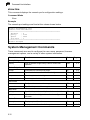
Quidway WB2011 Wireless Bridge
User Guide
User Guide
Guide
Outdoor 5 GHz Wireless Bridge
IEEE 802.11a Wireless Bridge
WB2011
F1.1.1.0 E102004-R01
Compliances
Federal Communication Commission Interference Statement
This equipment generates, uses, and can radiate radio frequency energy and, if not
installed and used in accordance with the instruction manual, may cause interference to
radio communications. It has been tested and found to comply with the limits for a Class A
computing device pursuant to Subpart B of Part 15 of FCC Rules, which are designed to
provide reasonable protection against such interference when operated in a commercial
environment. Operation of this equipment in a residential area is likely to cause
interference, in which case the user, at his own expense, will be required to take whatever
measures may be required to correct the interference. You are cautioned that changes or
modifications not expressly approved by the party responsible for compliance could void
your authority to operate the equipment.
You may use unshielded twisted-pair (UTP) for RJ-45 connections - Category 3 or greater
for 10 Mbps connections, Category 5 for 100 Mbps connections.
Warnings: 1. Wear an anti-static wrist strap or take other suitable measures to prevent
electrostatic discharge when handling this equipment.
2. When connecting this device to a power outlet, connect the field ground
lead on the tri-pole power plug to a valid earth ground line to prevent
electrical hazards.
IMPORTANT NOTE: FCC Radiation Exposure Statement
This equipment complies with FCC radiation exposure limits set forth for an uncontrolled
environment. This equipment should be installed and operated with a minimum distance
of 20 centimeters (8 inches) between the radiator and your body. This transmitter must
not be co-located or operating in conjunction with any other antenna or transmitter.
Wireless 5 GHz Band Statement:
As the access point can operate in the 5150-5250 MHz frequency band it is limited by the
FCC, Industry Canada and some other countries to indoor use only so as to reduce the
potential for harmful interference to co-channel Mobile Satellite systems.
High power radars are allocated as primary users (meaning they have priority) of the
5250-5350 MHz and 5650-5850 MHz bands. These radars could cause interference and/
or damage to the access point when used in Canada.
The term “IC:” before the radio certification number only signifies that Industry Canada
technical specifications were met.
i
Safety Compliance
Power Cord Safety
Please read the following safety information carefully before installing the wireless
bridge:
Warning: Installation and removal of the unit must be carried out by qualified personnel
only.
• The unit must be connected to an earthed (grounded) outlet to comply with international
safety standards.
• Do not connect the unit to an A.C. outlet (power supply) without an earth (ground)
connection.
• The appliance coupler (the connector to the unit and not the wall plug) must have a
configuration for mating with an EN 60320/IEC 320 appliance inlet.
• The socket outlet must be near to the unit and easily accessible. You can only remove
power from the unit by disconnecting the power cord from the outlet.
• This unit operates under SELV (Safety Extra Low Voltage) conditions according to
IEC 60950. The conditions are only maintained if the equipment to which it is connected
also operates under SELV conditions.
France and Peru only
This unit cannot be powered from IT† supplies. If your supplies are of IT type, this unit
must be powered by 230 V (2P+T) via an isolation transformer ratio 1:1, with the
secondary connection point labelled Neutral, connected directly to earth (ground).
Impédance à la terre
†
Power Cord Set
U.S.A. and Canada The cord set must be UL-approved and CSA certified.
The minimum specifications for the flexible cord are:
- No. 18 AWG - not longer than 2 meters, or 16 AWG.
- Type SV or SJ
- 3-conductor
The cord set must have a rated current capacity of at least 10 A
The attachment plug must be an earth-grounding type with NEMA 5-15P (15 A, 125
V) or NEMA 6-15P (15 A, 250 V) configuration.
Denmark
The supply plug must comply with Section 107-2-D1, Standard DK2-1a or DK2-5a.
Switzerland
The supply plug must comply with SEV/ASE 1011.
U.K.
The supply plug must comply with BS1363 (3-pin 13 A) and be fitted with a 5 A fuse
which complies with BS1362.
The mains cord must be <HAR> or <BASEC> marked and be of type HO3VVF3GO.75
(minimum).
Europe
The supply plug must comply with CEE7/7 (“SCHUKO”).
The mains cord must be <HAR> or <BASEC> marked and be of type HO3VVF3GO.75
(minimum).
IEC-320 receptacle.
ii
Veuillez lire à fond l'information de la sécurité suivante avant d'installer le wireless
bridge:
AVERTISSEMENT: L’installation et la dépose de ce groupe doivent être confiés à un
personnel qualifié.
• Ne branchez pas votre appareil sur une prise secteur (alimentation électrique) lorsqu'il
n'y a pas de connexion de mise à la terre (mise à la masse).
• Vous devez raccorder ce groupe à une sortie mise à la terre (mise à la masse) afin de
respecter les normes internationales de sécurité.
• Le coupleur d’appareil (le connecteur du groupe et non pas la prise murale) doit
respecter une configuration qui permet un branchement sur une entrée d’appareil EN
60320/IEC 320.
• La prise secteur doit se trouver à proximité de l’appareil et son accès doit être facile.
Vous ne pouvez mettre l’appareil hors circuit qu’en débranchant son cordon électrique
au niveau de cette prise.
• L’appareil fonctionne à une tension extrêmement basse de sécurité qui est conforme à
la norme IEC 60950. Ces conditions ne sont maintenues que si l’équipement auquel il
est raccordé fonctionne dans les mêmes conditions.
France et Pérou uniquement:
Ce groupe ne peut pas être alimenté par un dispositif à impédance à la terre. Si vos
alimentations sont du type impédance à la terre, ce groupe doit être alimenté par une
tension de 230 V (2 P+T) par le biais d’un transformateur d’isolement à rapport 1:1, avec
un point secondaire de connexion portant l’appellation Neutre et avec raccordement
direct à la terre (masse).
Cordon électrique - Il doit être agréé dans le pays d’utilisation
Etats-Unis et Canada: Le cordon doit avoir reçu l’homologation des UL et un certificat de la CSA.
Les spe'cifications minimales pour un cable flexible sont AWG No. 18, ouAWG No.
16 pour un cable de longueur infe'rieure a` 2 me'tres.
- type SV ou SJ
- 3 conducteurs
Le cordon doit être en mesure d’acheminer un courant nominal d’au moins 10 A.
La prise femelle de branchement doit être du type à mise à la terre (mise à la
masse) et respecter la configuration NEMA 5-15P (15 A, 125 V) ou NEMA 6-15P
(15 A, 250 V).
Danemark:
La prise mâle d’alimentation doit respecter la section 107-2 D1 de la norme DK2 1a
ou DK2 5a.
Suisse:
La prise mâle d’alimentation doit respecter la norme SEV/ASE 1011.
Europe
La prise secteur doit être conforme aux normes CEE 7/7 (“SCHUKO”)
LE cordon secteur doit porter la mention <HAR> ou <BASEC> et doit être de type
HO3VVF3GO.75 (minimum).
iii
Bitte unbedingt vor dem Einbauen des wireless bridges die folgenden
Sicherheitsanweisungen durchlesen:
WARNUNG: Die Installation und der Ausbau des Geräts darf nur durch Fachpersonal
erfolgen.
• Das Gerät sollte nicht an eine ungeerdete Wechselstromsteckdose angeschlossen
werden.
• Das Gerät muß an eine geerdete Steckdose angeschlossen werden, welche die
internationalen Sicherheitsnormen erfüllt.
• Der Gerätestecker (der Anschluß an das Gerät, nicht der Wandsteckdosenstecker) muß
einen gemäß EN 60320/IEC 320 konfigurierten Geräteeingang haben.
• Die Netzsteckdose muß in der Nähe des Geräts und leicht zugänglich sein. Die
Stromversorgung des Geräts kann nur durch Herausziehen des Gerätenetzkabels aus
der Netzsteckdose unterbrochen werden.
• Der Betrieb dieses Geräts erfolgt unter den SELV-Bedingungen
(Sicherheitskleinstspannung) gemäß IEC 60950. Diese Bedingungen sind nur gegeben,
wenn auch die an das Gerät angeschlossenen Geräte unter SELV-Bedingungen
betrieben werden.
Stromkabel. Dies muss von dem Land, in dem es benutzt wird geprüft werden:
Schweiz
Dieser Stromstecker muß die SEV/ASE 1011Bestimmungen einhalten.
Europe
Das Netzkabel muß vom Typ HO3VVF3GO.75 (Mindestanforderung) sein und die
Aufschrift <HAR> oder <BASEC> tragen.
Der Netzstecker muß die Norm CEE 7/7 erfüllen (”SCHUKO”).
iv
Contents
Chapter 1: Introduction
Package Checklist
Hardware Description
Component Description
System Configuration
System Components
Point-to-Point Configuration
Point-to-Multipoint Configuration
Features and Benefits
System Defaults
1-1
1-1
1-2
1-2
1-5
1-5
1-5
1-5
1-6
1-7
Chapter 2: Bridge Link Planning
Data Rates
Radio Path Planning
Antenna Height
Antenna Position and Orientation
Radio Interference
Weather Conditions
Ethernet Cabling
Grounding
2-1
2-1
2-2
2-3
2-4
2-5
2-5
2-6
2-6
Chapter 3: Hardware Installation
Testing Basic Link Operation
Mount the Unit
Using the Pole-Mounting Bracket
Using the Wall-Mounting Bracket
Connect the External Antenna
Connect Cables to the Unit
Connect the Power Injector
Align Antennas
3-1
3-1
3-1
3-1
3-3
3-4
3-5
3-5
3-6
Chapter 4: Initial Configuration
Initial Setup through the CLI
Initial Configuration Steps
Using the Web-based Management Setup Wizard
4-1
4-1
4-2
4-3
Chapter 5: System Configuration
Advanced Configuration
System Identification
TCP / IP Settings
Filter Control
5-1
5-1
5-2
5-3
5-6
v
Contents
SNMP
Administration
System Log
Wireless Distribution System (WDS)
Bridge
Spanning Tree Protocol (STP)
Radio Interface
Radio Settings (802.11a)
Security
Status Information
Wireless Bridge Status
Station Status
Event Logs
Chapter 6: Command Line Interface
Using the Command Line Interface
Accessing the CLI
Telnet Connection
Entering Commands
Keywords and Arguments
Minimum Abbreviation
Command Completion
Getting Help on Commands
Partial Keyword Lookup
Negating the Effect of Commands
Using Command History
Understanding Command Modes
Exec Commands
Configuration Commands
Command Line Processing
Command Groups
General Commands
configure
end
exit
ping
reset
show history
show line
System Management Commands
country
prompt
system name
username
vi
5-7
5-10
5-13
5-17
5-18
5-21
5-25
5-25
5-28
5-33
5-33
5-35
5-36
6-1
6-1
6-1
6-1
6-2
6-2
6-2
6-2
6-2
6-3
6-3
6-3
6-4
6-4
6-4
6-5
6-6
6-6
6-7
6-7
6-7
6-8
6-9
6-9
6-10
6-10
6-11
6-12
6-12
6-13
Contents
password
ip http port
ip http server
show system
show version
System Logging Commands
logging on
logging host
logging console
logging level
logging facility-type
show logging
System Clock Commands
sntp-server ip
sntp-server enable
sntp-server date-time
sntp-server daylight-saving
sntp-server timezone
show sntp
SNMP Commands
snmp-server community
snmp-server contact
snmp-server enable server
snmp-server host
snmp-server location
show snmp
Flash/File Commands
bootfile
copy
delete
dir
WDS Commands
wds mac-address
wds enable
show wds
Bridge Commands
bridge timeout
bridge stp-bridge spanning-tree
bridge stp-bridge forward-time
bridge stp-bridge hello-time
bridge stp-bridge max-age
bridge stp-bridge priority
bridge stp-port path-cost
bridge stp-port priority
bridge stp-port portfast
6-13
6-14
6-14
6-15
6-15
6-16
6-16
6-17
6-17
6-18
6-18
6-19
6-19
6-20
6-20
6-21
6-21
6-22
6-22
6-23
6-23
6-24
6-25
6-25
6-26
6-26
6-27
6-27
6-28
6-29
6-30
6-30
6-31
6-31
6-32
6-33
6-33
6-34
6-34
6-35
6-35
6-36
6-37
6-37
6-38
vii
Contents
bridge stp-port spanning-disabled
show bridge
Filtering Commands
filter ap-manage
filter ethernet-type enable
filter ethernet-type protocol
show filters
Ethernet Interface Commands
interface ethernet
dns server
ip address
ip dhcp
shutdown
show interface ethernet
Wireless Interface Commands
interface wireless
description
speed
channel
turbo
beacon-interval
dtim-period
fragmentation-length
rts-threshold
encryption
key
transmit-key
transmit-power
shutdown
show interface wireless
VLAN Commands
vlan
native-vlanid
6-39
6-39
6-40
6-40
6-41
6-41
6-42
6-43
6-43
6-43
6-44
6-45
6-46
6-46
6-47
6-48
6-48
6-49
6-49
6-50
6-50
6-51
6-52
6-52
6-53
6-54
6-55
6-56
6-56
6-57
6-58
6-58
6-59
Appendix A: Troubleshooting
A-1
Appendix B: Specifications
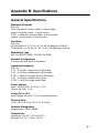
General Specifications
B-1
B-1
viii
Contents
Appendix C: Cables and Pinouts
Twisted-Pair Cable Assignments
10/100BASE-TX Pin Assignments
Straight-Through Wiring
Crossover Wiring
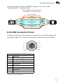
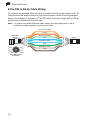
8-Pin DIN Connector Pinout
8-Pin DIN to RJ-45 Cable Wiring
C-1
C-1
C-1
C-2
C-2
C-3
C-4
Glossary
Index
ix
Contents
x
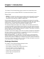
Chapter 1: Introduction
The Outdoor 5 GHz Wireless Bridge system consists of two models that provide
point-to-point or point-to-multipoint IEEE 802.11a wireless links between remote
Ethernet LANs:
• WB2011– Provides only external antenna options and is designed to operate as
the “Master” bridge in point-to-multipoint configurations, supporting wireless
connections to as many as 16 WB2011 Slave units.
Each wireless bridge model is housed in a weatherproof enclosure for mounting
outdoors and includes its own bracket kits for attaching to a wall, pole, radio mast, or
tower structure. The wireless bridge is powered through its Ethernet cable
connection from a power injector module that is installed indoors.
The wireless bridge system offers a fast, reliable, and cost-effective solution for
connectivity between remote Ethernet wired LANs or to provide Internet access to
an isolated site. The system is also easy to install and operate, ideal for situations
where a wired link may be difficult or expensive to deploy. The wireless connection
provides data rates of up to 108 Mbps.
In addition, both wireless bridge models offer full network management capabilities
through an easy-to-use web interface, a command-line interface, and support for
Simple Network Management Protocol (SNMP) tools.
Radio Characteristics – The IEEE 802.11a standard uses a radio modulation
technique known as Orthogonal Frequency Division Multiplexing (OFDM), and a
shared collision domain (CSMA/CA). It operates at the 5 GHz Unlicensed National
Information Infrastructure (UNII) band, providing a 54 Mbps half-duplex connection
in its normal mode or 108 Mbps in turbo mode.
Package Checklist
The Outdoor 5 GHz Wireless Bridge package includes:
• One Outdoor 5 GHz Wireless Bridge
• One Category 5 network cable, length 100 ft (30 m)
• One power injector module and power cord
• One N-type RF coaxial cable (WB2011 only)
• Outdoor pole-mounting bracket kit
• Outdoor wall-mounting bracket kit
• This User Guide
1-1
1
Introduction
Inform your dealer if there are any incorrect, missing or damaged parts. If possible,
retain the carton, including the original packing materials. Use them again to repack
the product in case there is a need to return it.
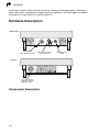
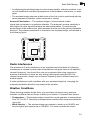
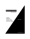
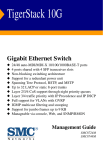
Hardware Description
Bottom View
Ethernet Port
(Also Supplies Power)
RSSI Connector with
Protective Cap
Top View
N-Type External
Antenna Connector
(WB2011 only)
Component Description
1-2
Grounding Point
Screw
Hardware Description
1
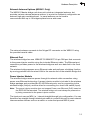
External Antenna Options (WB2011 Only)
The WB2011 Master bridge unit does not include an integrated antenna, but
provides various external antenna options. In a point-to-multipoint configuration an
external high-gain omnidirectional, or panel antenna can be used to
communicate with up to 16 bridges spread over a wide area.
The external antenna connects to the N-type RF connector on the WB2011 using
the provided coaxial cable.
Ethernet Port
The wireless bridge has one 10BASE-T/100BASE-TX 8-pin DIN port that connects
to the power injector module using the included Ethernet cable. The Ethernet port
connection provides power to the wireless bridge as well as a data link to the local
network.
The wireless bridge appears as an Ethernet node and performs a bridging function
by moving packets from the wired LAN to the remote end of the wireless bridge link.
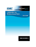
Power Injector Module
The wireless bridge receives power through its network cable connection using
power-over-Ethernet technology. A power injector module is included in the wireless
bridge package and provides two RJ-45 Ethernet ports, one for connecting to the
wireless bridge (Output), and the other for connecting to a local LAN switch (Input).
Note: The power injector module does not support Power over Ethernet (PoE) based on
the IEEE 802.3af standard. The wireless bridge unit must always be powered on
by being connected to the power injector module.
The Input port uses an MDI (i.e., internal straight-through) pin configuration. You can
therefore use straight-through twisted-pair cable to connect this port to most network
interconnection devices such as a switch or router that provide MDI-X ports.
1-3
1
Introduction
However, when connecting the access point to a workstation or other device that
does not have MDI-X ports, you must use crossover twisted-pair cable.
LED Indicator
Input
Data from Local
Network Switch
AC Power Socket
(Hidden)
Output
Data and Power to
Wireless Bridge
The wireless bridge does not have a power switch. It is powered on when its
Ethernet port is connected to the power injector module, and the power injector
module is connected to an AC power source. The power injector includes one LED
indicator that turns on when AC power is applied.
The power injector module automatically adjusts to any AC voltage between
100-240 volts at 50 or 60 Hz. No voltage range settings are required.
Warning: The power injector module is designed for indoor use only. Never mount the
power injector outside with the wireless bridge unit.
Receive Signal Strength Indicator (RSSI) BNC Connector
The RSSI connector provides an output voltage that is proportional to the received
radio signal strength. A DC voltmeter can be connected the this port to assist in
aligning the antennas at both ends of a wireless bridge link. For more information,
see “Align Antennas” on page 3-6.
Grounding Point
Even though the wireless bridge includes its own built-in lightning protection, it is
important that the unit is properly connected to ground. A grounding screw is
provided for attaching a ground wire to the unit.
Wall- and Pole-Mounting Bracket Kits
The wireless bridge includes bracket kits that can be used to mount the bridge to a
wall, pole, radio mast, or part of a tower structure.
1-4
System Configuration
1
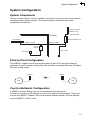
System Configuration
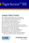
System Components
At each location where a unit is installed, it must be connected to the local network
using the power injector module. The following figure illustrates the system
component connections.
External Antenna
(WB2011 only)
Indoor
RF Coaxial Cable
Outdoor
Wireless Bridge Unit
LAN Switch
Ethernet Cable
Ethernet Cable
Power
Injector
AC Power
Ground Wire
Point-to-Point Configuration
Two WB2011 bridges can form a wireless point-to-point link using the external
antennas. A point-to-point configuration can provide a moderate data rate (36 Mbps)
link over a long range .
WB2011
LAN
WB2011
LAN
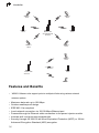
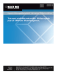
Point-to-Multipoint Configuration
A WB2011 wireless bridge can use an omnidirectional antenna to
connect to as many as 16 bridges in a point-to-multipoint configuration. There can
only be one WB2011 “Master” unit in the wireless bridge network, all other bridges
must be WB2011 “Slave” units.
1-5
1
Introduction
WB2011
Slave
WB2011
Slave
WB2011
Slave
WB2011
Master with
Omnidirectional
Antenna
WB2011
Slave
WB2011
Slave
WB2011
Slave
WB2011
Slave
WB2011
Master with
Antenna
WB2011
Slave
WB2011
Features and Benefits
• WB2011 Master units support point-to-multipoint links using various external
antenna options
•
•
•
•
•
•
•
Maximum data rate up to 108 Mbps
Outdoor weatherproof design
IEEE 802.11a compliant
Local network connection via 10/100 Mbps Ethernet port
Powered through its Ethernet cable connection to the power injector module
Includes wall- and pole-mount bracket kits
Security through 64/128/152-bit Wired Equivalent Protection (WEP) or 128-bit
Advanced Encryption Standard (AES) encryption
1-6
System Defaults
1
• Scans all available channels and selects the best channel and data rate based on
the signal-to-noise ratio
• Manageable through an easy-to-use web-browser interface, command line (via
Telnet), or SNMP network management tools
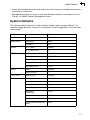
System Defaults
The following table lists some of the wireless bridge’s basic system defaults. To
reset the bridge defaults, use the CLI command “reset configuration” from the Exec
level prompt.
Feature
Parameter
Default
Identification
System Name
Outdoor Bridge
Administration
User Name
admin
General
TCP/IP
VLANs
Password
null
HTTP Server
Enabled
HTTP Server Port
80
IP Address
192.168.1.1
Subnet Mask
255.255.255.0
Default Gateway
0.0.0.0
Primary DNS IP
0.0.0.0
Secondary DNS IP
0.0.0.0
Status
DIsbaled
Native VLAN ID
1
Filter Control
Ethernet Type
Disabled
SNMP
Status
Enabled
Location
null
Contact
Contact
Community (Read Only)
public
Community
(Read/Write)
private
Traps
Enabled
Trap Destination IP Address
null
Trap Destination Community
Name
public
1-7
1
Introduction
Feature
Parameter
Default
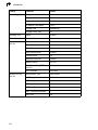
System Logging
Syslog
Disabled
Logging Host
Disabled
Logging Console
Disabled
IP Address / Host Name
0.0.0.0
Logging Level
Informational
Logging Facility Type
16
Spanning Tree
Status
Enabled
Ethernet Interface
Speed and Duplex
Auto
Wireless Interface
802.11a
Status
Enabled
Turbo Mode
Disabled
Wireless Security
802.11a
1-8
Radio Channel
Default to first channel
Auto Channel Select
Enabled
Transmit Power
Full
Maximum Data Rate
54 Mbps
Beacon Interval
100 TUs
Data Beacon Rate (DTIM
Interval)
2 beacons
RTS Threshold
2347 bytes
Authentication Type
Open System
AES Encryption
Disabled
WEP Encryption
Disabled
WEP Key Length
128 bits
WEP Key Type
Hexadecimal
WEP Transmit Key Number
1
WEP Keys
null
Chapter 2: Bridge Link Planning
The Outdoor 5 GHz Wireless Bridge supports fixed point-to-point or
point-to-multipoint wireless links. A single link between two points can be used to
connect a remote site to larger core network. Multiple bridge links can provide a way
to connect widespread Ethernet LANs.
For each link in a wireless bridge network to be reliable and provide optimum
performance, some careful site planning is required. This chapter provides guidance
and information for planning your wireless bridge links.
Note: The planning and installation of the wireless bridge requires professional
personnel that are trained in the installation of radio transmitting equipment. The
user is responsible for compliance with local regulations concerning items such as
antenna power, use of lightning arrestors, grounding, and radio mast or tower
construction. Therefore, it is recommended to consult a professional contractor
knowledgeable in local radio regulations prior to equipment installation.
Data Rates
Using the antenna, the WB2011 Slave bridge can operate over a range of
up to long-distance or provide a high-speed connection.
2-1
2
Bridge Link Planning
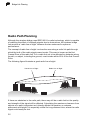
Radio Path Planning
Although the wireless bridge uses IEEE 802.11a radio technology, which is capable
of reducing the effect of multipath signals due to obstructions, the wireless bridge
link requires a “radio line-of-sight” between the two antennas for optimum
performance.
The concept of radio line-of-sight involves the area along a radio link path through
which the bulk of the radio signal power travels. This area is known as the first
Fresnel Zone of the radio link. For a radio link not to be affected by obstacles along
its path, no object, including the ground, must intrude within 60% of the first Fresnel
Zone.
The following figure illustrates a good radio line-of-sight.
Visual Line of Sight
Radio Line of Sight
If there are obstacles in the radio path, there may still be a radio link but the quality
and strength of the signal will be affected. Calculating the maximum clearance from
objects on a path is important as it directly affects the decision on antenna
placement and height. It is especially critical for long-distance links, where the radio
signal could easily be lost.
2-2
Radio Path Planning
2
When planning the radio path for a wireless bridge link, consider these factors:
• Avoid any partial line-of-sight between the antennas.
• Be cautious of trees or other foliage that may be near the path, or may grow and
obstruct the path.
• Be sure there is enough clearance from buildings and that no building construction
may eventually block the path.
• Check the topology of the land between the antennas using topographical maps,
aerial photos, or even satellite image data (software packages are available that
may include this information for your area)
• Avoid a path that may incur temporary blockage due to the movement of cars,
trains, or aircraft.
Antenna Height
A reliable wireless link is usually best achieved by mounting the antennas at each
end just high enough for a clear radio line of sight between them. The minimum
height required depends on the distance of the link, obstacles that may be in the
path, topology of the terrain, and the curvature of the earth (for links over 3 miles).
For long-distance links, a mast or pole may need to be contsructed to attain the
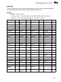
minimum required height. Use the following table to estimate the required minimum
clearance above the ground or path obstruction.
.
Total Link Distance
Max Clearance for
60% of First Fresnel
Zone at 5.8 GHz
Approximate
Clearance for
Earth Curvature
Total Clearance
Required at
Mid-point of Link
0.25 mile (402 m)
4.5 ft (1.4 m)
0
4.5 ft (1.4 m)
0.5 mile (805 m)
6.4 ft (1.95 m)
0
6.4 ft (1.95 m)
1 mile (1.6 km)
9 ft (2.7 m)
0
9 ft (2.7 m)
2 miles (3.2 km)
12.7 ft (3.9 m)
0
12.7 ft (3.9 m)
3 miles (4.8 km)
15.6 ft (4.8 m)
1.8 ft (0.5 m)
17.4 ft (5.3 m)
4 miles (6.4 km)
18 ft (5.5 m)
3.2 ft (1.0 m)
21.2 ft (6.5 m)
5 miles (8 km)
20 ft (6.1 m)
5 ft (1.5 m)
25 ft (7.6 m)
7 miles (11.3 km)
24 ft (7.3 m)
9.8 ft (3.0 m)
33.8 ft (10.3 m)
9 miles (14.5 km)
27 ft (8.2 m)
16 ft (4.9 m)
43 ft (13.1 m)
12 miles (19.3 km)
31 ft (9.5 m)
29 ft (8.8 m)
60 ft (18.3 m)
2-3
2
Bridge Link Planning
Total Link Distance
Max Clearance for
60% of First Fresnel
Zone at 5.8 GHz
Approximate
Clearance for
Earth Curvature
Total Clearance
Required at
Mid-point of Link
15 miles (24.1 km)
35 ft (10.7 m)
45 ft (13.7 m)
80 ft (24.4 m)
17 miles (27.4 km)
37 ft (11.3 m)
58 ft (17.7 m)
95 ft (29 m)
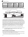
Note that to avoid any obstruction along the path, the height of the object must be
added to the minimum clearance required for a clear radio line-of-sight. Consider the
following simple example, illustrated in the figure below.
Radio Line of Sight
Visual Line of Sight
3 miles (4.8 km)
2.4 m
A
5.4 m
B
1.4 m
9m
20 m
17 m
12 m
A wireless bridge link is deployed to connect building A to building B, which is
located three miles (4.8 km) away. Mid-way between the two buidings is a small
tree-covered hill. From the above table it can be seen that for a three-mile link, the
object clearance required at the mid-point is 5.3 m (17.4 ft). The tree-tops on the hill
are at an elevation of 17 m (56 ft), so the antennas at each end of the link need to be
at least 22.3 m (73 ft) high. Building A is six stories high, or 20 m (66 ft), so a 2.3 m
(7.5 ft) mast or pole must be contructed on its roof to achieve the required antenna
height. Building B is only three stories high, or 9 m (30 ft), but is located at an
elevation that is 12 m (39 ft) higher than bulding A. To mount an anntena at the
required height on building B, a mast or pole of only 1.3 m (4.3 ft) is needed.
Warning: Never construct a radio mast, pole, or tower near overhead power lines.
Note: Local regulations may limit or prevent construction of a high radio mast or tower. If
your wireless bridge link requires a high radio mast or tower, consult a
professional contractor for advice.
Antenna Position and Orientation
Once the required antenna height has been determined, other factors affecting the
precise position of the wireless bridge must be considered:
• Be sure there are no other radio antennas within 2 m (6 ft) of the wireless bridge
• Place the wireless bridge away from power and telephone lines
2-4
Radio Path Planning
2
• Avoid placing the wireless bridge too close to any metallic, reflective surfaces, such
as roof-installed air-conditioning equipment, tinted windows, wire fences, or water
pipes
• The wireless bridge antennas at both ends of the link must be positioned with the
same polarization direction, either horizontal or vertical
Antenna Polarization — The wireless bridge’s antenna sends a radio
signal that is polarized in a particular direction. The antenna’s receive sensitivity is
also higher for radio signals that have the same polarization. To maximize the
performance of the wireless link, both antennas must be set to the same polarization
direction. The antenna polarization is marked on the wireless bridge, as indicated in
the following figure.
V
H
Radio Interference
The avoidance of radio interference is an important part of wireless link planning.
Interference is caused by other radio transmissions using the same or an adjacent
channel frequency. You should first scan your proposed site using a spectrum
analyzer to determine if there are any strong radio signals using the 802.11a
channel frequencies. Always use a channel frequency that is furthest away from
another signal.
If radio interference is still a problem with your wireless bridge link, changing the
antenna polarization direction may improve the situation.
Weather Conditions
When planning wireless bridge links, you must take into account any extreme
weather conditions that are known to affect your location. Consider these factors:
• Temperature — The wireless bridge is tested for normal operation in temperatures
from -33°C to 55°C. Operating in temperatures outside of this range may cause the
unit to fail.
• Wind Velocity — The wireless bridge can operate in winds up to 90 MPH and
survive higher wind speeds up to 125 MPH. You must consider the known
2-5
2
Bridge Link Planning
maximum wind velocity and direction at the site and be sure that any supporting
structure, such as a pole, mast, or tower, is built to withstand this force.
• Lightning — The wireless bridge includes its own built-in lightning protection.
However, you should make sure that the unit, any supporting structure, and cables
are all properly grounded. Additional protection using lightning rods, lightning
arrestors, or surge suppressors may also be employed.
• Rain — The wireless bridge is weatherproofed against rain. Also, prolonged heavy
rain has no significant effect on the radio signal. However, you may want to apply
sealing tape around the Ethernet port connector for extra protection. If moisture
enters the connector, it may cause a degradation in performance or even a
complete failure of the link.
• Snow and Ice — Falling snow, like rain, has no significant effect on the radio
signal. However, a build up of snow or ice on antennas may cause the link to fail.
In this case, the snow or ice has to be cleared from the antennas to restore
operation of the link.
Ethernet Cabling
When a suitable antenna location has been determined, you must plan a cable route
form the wireless bridge outdoors to the power injector module indoors. Consider
these points:
• The Ethernet cable length should never be longer than 100 m (328 ft)
• Determine a building entry point for the cable
• Determine if conduits, bracing, or other structures are required for safety or
protection of the cable
• For lightning protection at the power injector end of the cable, it is recommended
to use a lightning arrestor immediately before the cable enters the building
Grounding
It is important that the wireless bridge, cables, and any supporting structures are
properly grounded. The wireless bridge unit includes a grounding screw for
attaching a ground wire. Be sure that grounding is available and that it meets local
and national electrical codes.
2-6
Chapter 3: Hardware Installation
Before mounting antennas to set up your wireless bridge links, be sure you have
selected appropriate locations for each antenna. Follow the guidance and
information in Chapter 2, “Wireless Link Planning.”
Also, before mounting units in their intended locations, you should first perform initial
configuration and test the basic operation of the wireless bridge links in a controlled
environment over a very short range. (See the section “Testing Basic Link
Operation” in this chapter.)
The wireless bridge includes its own bracket kit for mounting the unit to a 1.5 to
2 inch diameter steel pole or tube. The pole-mounting bracket allows the unit to be
mounted to part of a radio mast or tower structure. The unit also has a wall-mounting
bracket kit that enables it to be fixed to a building wall or roof when using an external
antenna (for WB2011).
Hardware installation of the wireless bridge involves these steps:
1.
Mount the unit on a wall, pole, mast, or tower using the appropriate mounting
bracket.
2.
If using an external antenna, mount the antenna nearby on the same
supporting structure as the bridge and connect it to the bridge unit.
3.
Connect the Ethernet cable and a grounding wire to the unit.
4.
Connect the power injector to the Ethernet cable, a local LAN switch, and an
AC power source.
5.
Align antennas at both ends of the link.
Testing Basic Link Operation
Set up the units over a very short range (15 to 25 feet), either outdoors or indoors.
Connect the units as indicated in this chapter and be sure to perform all the basic
configuration tasks outlined in Chapter 4, “Initial Configuration.” When you are
satisfied that the links are operating correctly, proceed to mount the units in their
intended locations.
Mount the Unit
Using the Pole-Mounting Bracket
Perform the following steps to mount the unit to a 1.5 to 2 inch diameter steel pole or
tube using the mounting bracket:
1.
Always attach the bracket to a pole with the open end of the mounting grooves
facing up.
3-1
3
2.
Hardware Installation
Place the U-shaped part of the bracket around the pole and tighten the securing
nut just enough to hold the bracket to the pole. (The bracket may need to be
rotated around the pole during the alignment process.)
Attach bracket to
pole with mounting
grooves facing up
3.
Use the included nuts to tightly secure the wireless bridge to the bracket. Be
sure to take account of the antenna polarization direction; both antennas in a
link must be mounted with the same polarization.
Antenna Polarization
Direction
3-2
Mount the Unit
3
Mounting on Larger Diameter Poles
In addition, there is a method for attaching the pole-mounting bracket to a pole that
is 2 to 5 inches in diameter using an adjustable steel band clamp (not included in the
kit). A steel band clamp up to 0.5 inch (1.27 cm) wide can be threaded through the
main part of the bracket to secure it to a larger diameter pole without using the
U-shaped part of the bracket. This method is illustrated in the following figure.
Steel Band Clamp
Using the Wall-Mounting Bracket
Perform the following steps to mount the unit to a wall using the wall-mounting
bracket:
1.
Always attach the bracket to a wall with the open end of the mounting grooves
facing up (see following figure).
Mounting Grooves
3-3
3
Hardware Installation
2.
Position the bracket in the intended location and mark the position of the three
mounting screw holes.
3.
Drill three holes in the wall that match the screws and wall plugs included in the
bracket kit, then secure the bracket to the wall.
4.
Use the included nuts to tightly secure the wireless bridge to the bracket.
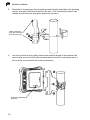
Connect the External Antenna
If deploying a WB2011 Master bridge unit in a point-to-multipoint configuration,
you need to mount the external antenna and connect it to the bridge. Perform these
steps:
1.
Mount the external antenna to the same supporting structure as the bridge,
within 3 m (10 ft) distance, using the bracket supplied in the antenna package.
2.
Connect the antenna to the bridge’s N-type connector using the provided RF
coaxial cable.
3.
Apply weatherproofing tape (not included) to the antenna connectors to help
prevent water entering the connectors.
External
Omnidirectional
Antenna
N-type
Connector
Coaxial Cable
3-4
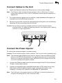
Connect Cables to the Unit
3
Connect Cables to the Unit
1.
Attach the Ethernet cable to the Ethernet port on the wireless bridge.
Note: The Ethernet cable included with the package is 30 m (100 ft) long. To wire a
longer cable (maximum 100 m, 325 ft), follow the connector pinout information in
Appendix B.
2.
For extra protection against rain or moisture, apply weatherproofing tape (not
included) around the Ethernet connector.
3.
Be sure to ground the unit with an appropriate grounding wire (not included) by
attaching it to the grounding screw on the unit.
Caution: Be sure that grounding is available and that it meets local and national
electrical codes. For additional lightning protection, use lightning rods, lightning
arrestors, or surge suppressors.
Ethernet Cable
Ground Wire
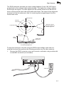
Connect the Power Injector
To connect the wireless bridge to a power source:
Caution: Do not install the power injector outdoors. The unit is for indoor installation only.
Note: The wireless bridge’s Ethernet port does not support Power over Ethernet (PoE)
based on the IEEE 802.3af standard. You cannot power the unit by connecting it
directly to a network switch that provides IEEE 802.3af PoE. Always connect the
unit to the included power injector module.
1.
Connect the Ethernet cable from the wireless bridge to the RJ-45 port labeled
“Output” on the power injector.
2.
Connect a straight-through unshielded twisted-pair (UTP) cable from a local
LAN switch to the RJ-45 port labeled “Input” on the power injector. Use
Category 5 or better UTP cable for 10/100BASE-TX connections.
Note: The RJ-45 port on the power injector is an MDI port. If connecting directly to a
computer for testing the link, use a crossover cable.
3-5
3
Hardware Installation
AC power
Ethernet cable
from LAN switch
Inp
ut
Ou
tpu
t
Power LED indicator
Ethernet cable to
wireless bridge
3.
Insert the power cable plug directly into the standard AC receptacle on the
power injector.
4.
Plug the other end of the power cable into a grounded, 3-pin socket, AC power
source.
Note: For International use, you may need to change the AC line cord. You must use a
line cord set that has been approved for the receptacle type in your country.
5.
Check the LED on top of the power injector to be sure that power is being
supplied to the wireless bridge through the Ethernet connection.
Align Antennas
After wireless bridge units have been mounted, connected, and their radios are
operating, the antennas must be accurately aligned to ensure optimum performance
on the links. This alignment process is particularly important for long-range
point-to-point links. In a point-to-multipoint configuration the Master bridge uses an
omnidirectional antenna, which does not require alignment, but Slave
bridges still need to be correctly aligned with the Master bridge antennna.
• Point-to-Point Configurations – In a point-to-point configuration the alignment
process requires two people at each end of the link. The use of cell phones or
two-way radio communication may help with coordination. To start, you can just
point the antennas at each other, using binoculars or a compass to set the general
direction. For accurate alignment, you must connect a DC voltmeter to the RSSI
connector on the wireless bridge and monitor the voltage as the antenna moves
horizontally and vertically.
• Point-to-Multipoint Configurations – In a point-to-multipoint configuration all
Slave bridges must be aligned with the Master bridge antenna. The alignment
process is the same as in point-to-point links, but only the Slave end of the link
requires precise alignment.
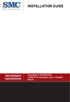
3-6
Align Antennas
3
The RSSI connector provides an output voltage between 0 and 3.28 VDC that is
proportional to the received radio signal strength. The higher the voltage reading,
the stronger the signal. The radio signal from the remote antenna can be seen to
have a strong central main lobe and smaller side lobes. The object of the alignment
process is to set the antenna so that it is receiving the strongest signal from the
central main lobe.
Vertical Scan
Remote
Antenna
Maximum Signal
Strength Position for
Vertical Alignment
Horizontal Scan
Main Lobe
Maximum
RSSI Voltage
RSSI
Voltage
Side Lobe
Maximum
Maximum Signal Strength Position
for Horizontal Alignment
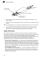
To align the antennas in the link using the RSSI output voltage, start with one
antenna fixed and then perform the following procedure on the other antenna:
1.
Remove the RSSI connector cover and connect a voltmeter using a cable with
a male BNC connector (not included).
RSSI BNC
Connection
Voltmeter
3-7
3
Hardware Installation
2.
Pan the antenna horizontally back and forth by rotating the mounting bracket
around the pole while checking the RSSI voltage.
3.
Find the point where the signal is strongest (highest voltage) and secure the
mounting bracket firmly to the pole.
Note: Sometimes there may not be a central lobe peak in the voltage because vertical
alignment is too far off; only two similar peaks for the side lobes are detected. In
this case, fix the antenna halfway between the two peaks.
4.
Loosen the vertical adjustment nut on the mounting bracket and tilt the antenna
slowly up and down while checking the RSSI voltage.
5.
Find the point where the signal is strongest and secure the vertical adjustment
nut.
6.
Remove the voltmeter cable and replace the RSSI connector cover.
3-8
Chapter 4: Initial Configuration
The wireless bridge offers a variety of management options, including a web-based
interface, a command line interface (CLI), or using SNMP management software.
Most initial configuration steps can be made through the web browser interface
using the Setup Wizard (page 4-3). However, for units that do not have a preset
country code, you must first set the country code using the CLI.
Note: Units sold in some countries are not configured with a specific country code. You
must use the CLI to set the country code and enable wireless operation
(page 4-2).
The wireless bridge requests an IP address via DHCP by default. If no response is
received from a DHCP server, then the wireless bridge uses the default address
192.168.1.1. If this address is not compatible with your network, you can first
perform initial configuration using a PC that has IP settings compatible with this
subnet (for example, 192.168.1.2) and connecting it directly to the wireless bridge.
When the basic configuration is completed, you can set new IP settings for the
wireless bridge before connecting it to your network.
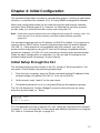
Initial Setup through the CLI
The wireless bridge provides access to the CLI through a Telnet connection. You
can open a Telnet session by performing these steps:
1.
From the host computer, enter the Telnet command and the IP address of the
wireless bridge unit (default 192.168.1.1 if not set via DHCP).
2.
At the prompt, enter “admin” for the user name.
3.
The default password is null, so just press [Enter] at the password prompt.
The CLI will display the “Outdoor Bridge#” prompt to show that you are using
executive access mode (i.e., Exec).
Username: admin
Password:
Outdoor Bridge#
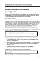
For a full description of how to use the CLI, see “Using the Command Line Interface”
on page 6-1. For a list of all the CLI commands and detailed information on using the
CLI, refer to “Command Groups” on page 6-6.
4-1
4
Initial Configuration
Initial Configuration Steps
Setting the Country Code – Regulations for wireless products differ from country to
country. Setting the country code restricts the wireless bridge to use only the radio
channels and power settings permitted in the specified country of operation. If the
wireless bridge unit is shipped with a preset country code, you are not permitted to
change it, as required by country regulations. If the unit is set to the default “99,” you
must set the country code to the country of operation.
At the Exec prompt, type “country ?” to display the list of country codes. Check the
code for your country, then enter the country command again followed by your
country code (e.g., IE for Ireland).
Outdoor Bridge#country ie
Outdoor Bridge#
Setting the IP Address – By default, the wireless bridge is configured to obtain IP
address settings from a DHCP server. You may also use the CLI to assign an IP
address that is compatible with your network.
Type “configure” to enter configuration mode, then type “interface ethernet” to
access the Ethernet interface-configuration mode.
Outdoor Bridge#configure
Outdoor Bridge(config)#interface ethernet
Outdoor Bridge(config-if)#
First type “no dhcp” to disable DHCP client mode. Then type “ip address ip-address
netmask gateway,” where “ip-address” is the wireless bridge’s IP address, “netmask”
is the network mask for the network, and “gateway” is the default gateway router.
Check with your system administrator to obtain an IP address that is compatible with
your network.
Outdoor Bridge(if-ethernet)#no ip dhcp
Outdoor Bridge(if-ethernet)#ip address 192.168.2.2 255.255.255.0
192.168.2.254
Outdoor Bridge(if-ethernet)#
After configuring the wireless bridge’s IP parameters, you can access the
management interface from anywhere within the attached network. The command
line interface can also be accessed using Telnet from any computer attached to the
network.
4-2
Using the Web-based Management Setup Wizard
4
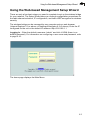
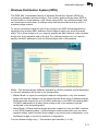
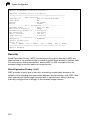
Using the Web-based Management Setup Wizard
There are only a few basic steps you need to complete to set up the wireless bridge
for your network. The Setup Wizard takes you through configuration procedures for
the radio channel selection, IP configuration, and basic WEP encryption for wireless
security.
The wireless bridge can be managed by any computer using a web browser
(Internet Explorer 5.0 or above, or Netscape Navigator 6.2 or above). Enter the IP
configured for the unit or the default IP address: http://192.168.1.1
Logging In – Enter the default username “admin” and click LOGIN (there is no
default password). For information on configuring a user name and password, refer
to page 5-10.
Huawei
The home page displays the Main Menu.
4-3
4
Initial Configuration
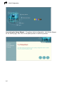
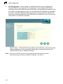
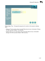
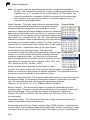
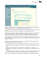
Launching the Setup Wizard – To perform initial configuration, click Setup Wizard
on the home page, then click on the [Next] button to start the process.
4-4
Using the Web-based Management Setup Wizard
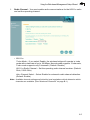
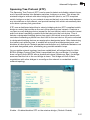
1.
4
Radio Channel – You must enable radio communications for the 802.11a radio
and set the operating channel.
• 802.11a
Turbo Mode – If you select Enable, the wireless bridge will operate in turbo
mode with a data rate of up to 108 Mbps. Normal mode supports 13 channels,
Turbo mode supports only 5 channels. (Default: Disable)
802.11a Radio Channel – Set the operating radio channel number. (Default:
56ch, 5.280 GHz)
Auto Channel Select – Select Enable for automatic radio channel detection.
(Default: Enable)
Note: Available channel settings are limited by local regulations which determine which
channels are available. (See “Maximum Channels” on page B-1.)
4-5
4
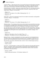
2.
Initial Configuration
IP Configuration – Either enable or disable (Dynamic Host Configuration
Protocol (DHCP) for automatic IP configuration. If you disable DHCP, then
manually enter the IP address and subnet mask. If a management station exists
on another network segment, then you must enter the IP address for a gateway
that can route traffic between these segments. Then enter the IP address for
the primary and secondary Domain Name Servers (DNS) servers to be used for
host-name to IP address resolution.
DHCP Client – With DHCP Client enabled, the IP address, subnet mask and
default gateway can be dynamically assigned to the access point by the
network DHCP server. (Default: Enable)
Note: If there is no DHCP server on your network, then the access point will
automatically start up with its default IP address, 192.168.1.1.
4-6
Using the Web-based Management Setup Wizard
3.
Security – Enable Wired Equivalent Privacy (WEP) encryption and set an
encryption key.
4.
Click Finish.
5.
Click the OK button to restart the access point.
4
4-7
4
4-8
Initial Configuration
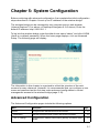
Chapter 5: System Configuration
Before continuing with advanced configuration, first complete the initial configuration
steps described in Chapter 4 to set up an IP address for the wireless bridge.
The wireless bridge can be managed by any computer using a web browser
(Internet Explorer 5.0 or above, or Netscape Navigator 6.2 or above). Enter the
default IP address: http://192.168.1.1
To log into the wireless bridge, enter the default user name “admin” and click LOGIN
(there is no default password). When the home page displays, click on Advanced
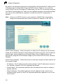
Setup. The following page will display.
The information in this chapter is organized to reflect the structure of the web
screens for easy reference. However, it is recommended that you configure a user
name and password as the first step under advanced configuration to control
management access to the wireless bridge (page 5-10).
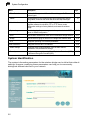
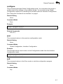
Advanced Configuration
The Advanced Configuration pages include the following options.
Menu
Description
Page
System
Configures basic administrative and client access
5-2
Identification
Specifies the system name, location and contact information
5-2
TCP / IP Settings
Configures the IP address, subnet mask, gateway, and domain name
servers
5-3
5-1
5
System Configuration
Menu
Description
Page
Filter Control
Enables VLAN support and filters traffic matching specific Ethernet
protocol types
5-6
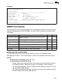
SNMP
Controls access to this wireless bridge from management stations
using SNMP, as well as the hosts that will receive trap messages
5-7
Administration
Configures user name and password for management access;
upgrades software from local file, FTP or TFTP server; resets
configuration settings to factory defaults; and resets the wireless
bridge
5-10
System Log
Controls logging of error messages; sets the system clock via SNTP
server or manual configuration
5-13
WDS
Sets the MAC addresses of other units in the wireless bridge network
5-17
Bridge
Sets the time for aging out entries in the bridge MAC address table
5-18
STP
Configures Spanning Tree Protocol parameters
5-21
Radio Interface A
Configures the IEEE 802.11a interface
5-25
Radio Settings
Configures radio signal parameters, such as radio channel,
transmission rate, and beacon settings
5-25
Security
Configures data encryption using Wired Equivalent Protection (WEP)
or Advanced Encryption Standard (AES)
5-28
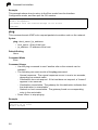
System Identification
The system information parameters for the wireless bridge can be left at their default
settings. However, modifying these parameters can help you to more easily
distinguish different devices in your network.
5-2
5
Advanced Configuration
System Name – An alias for the wireless bridge, enabling the device to be uniquely
identified on the network. (Default: Outdoor Bridge; Range: 1-22 characters)
Location – A text string that describes the system location. (Maximum length: 20
characters)
Contact – A text string that describes the system contact. (Maximum length: 255
characters)
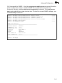
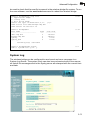
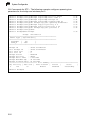
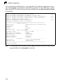
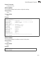
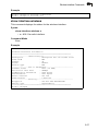
CLI Commands for System Identification – Enter the global configuration mode and
use the system name command to specify a new system name. Use the
snmp-server location and snmp-server contact commands to indicate the physical
location of the wireless bridge and define a system contact. Then return to the Exec
mode, and use the show system command to display the changes to the system
identification settings.
Outdoor
Outdoor
Outdoor
Outdoor
Outdoor
Outdoor
Bridge#configure
Bridge(config)#system name R&D
Bridge(config)#snmp-server location building-1
Bridge(config)#snmp-server contact Paul
Bridge(config)#exit
Bridge#show system
6-7
6-12
6-26
6-24
6-15
System Information
===================================================
Serial Number
: 0000000005
System Up time
: 0 days, 0 hours, 35 minutes, 56 seconds
System Name
: R&D
System Location
: building-1
System Contact
: Paul
System Country Code : US - UNITED STATES
MAC Address
: 00-30-F1-BE-F4-96
IP Address
: 192.168.1.1
Subnet Mask
: 255.255.255.0
Default Gateway
: 0.0.0.0
VLAN State
: DISABLED
Native VLAN ID
: 1
DHCP Client
: ENABLED
HTTP Server
: ENABLED
HTTP Server Port
: 80
Software Version
: v1.1.1.0
===================================================
Outdoor Bridge#
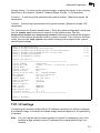
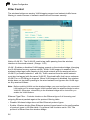
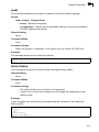
TCP / IP Settings
Configuring the wireless bridge with an IP address expands your ability to manage
the wireless bridge. A number of wireless bridge features depend on IP addressing
to operate.
Note: You can use the web browser interface to access IP addressing only if the
wireless bridge already has an IP address that is reachable through your
network.
5-3
5
System Configuration
By default, the wireless bridge will be automatically configured with IP settings from
a Dynamic Host Configuration Protocol (DHCP) server. However, if you are not
using a DHCP server to configure IP addressing, use the CLI to manually configure
the initial IP values (page 4-2). After you have network access to the wireless bridge,
you can use the web browser interface to modify the initial IP configuration, if
needed.
Note: If there is no DHCP server on your network, or DHCP fails, the wireless
bridge will automatically start up with a default IP address of 192.168.1.1.
DHCP Client (Enable) – Select this option to obtain the IP settings for the wireless
bridge from a DHCP (Dynamic Host Configuration Protocol) server. The IP address,
subnet mask, default gateway, and Domain Name Server (DNS) address are
dynamically assigned to the wireless bridge by the network DHCP server. (Default:
Disable)
DHCP Client (Disable) – Select this option to manually configure a static address for
the wireless bridge.
• IP Address: The IP address of the wireless bridge. Valid IP addresses consist of
four decimal numbers, 0 to 255, separated by periods.
• Subnet Mask: The mask that identifies the host address bits used for routing to
specific subnets.
• Default Gateway: The default gateway is the IP address of the router for the
wireless bridge, which is used if the requested destination address is not on the
local subnet.
5-4
5
Advanced Configuration
If you have management stations, DNS, or other network servers located on
another subnet, type the IP address of the default gateway router in the text field
provided. Otherwise, leave the address as all zeros (0.0.0.0).
• Primary and Secondary DNS Address: The IP address of Domain Name Servers
on the network. A DNS maps numerical IP addresses to domain names and can
be used to identify network hosts by familiar names instead of the IP addresses.
If you have one or more DNS servers located on the local network, type the IP
addresses in the text fields provided. Otherwise, leave the addresses as all zeros
(0.0.0.0).
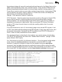
CLI Commands for TCP/IP Settings – From the global configuration mode, enter the
interface configuration mode with the interface ethernet command. Use the ip dhcp
command to enable the DHCP client, or no ip dhcp to disable it. To manually
configure an address, specify the new IP address, subnet mask, and default
gateway using the ip address command. To specify DNS server addresses use the
dns server command. Then use the show interface ethernet command from the
Exec mode to display the current IP settings.
Outdoor Bridge(config)#interface ethernet
Enter Ethernet configuration commands, one per line.
Outdoor Bridge(if-ethernet)#no ip dhcp
Outdoor Bridge(if-ethernet)#ip address 192.168.1.2
255.255.255.0 192.168.1.253
Outdoor Bridge(if-ethernet)#dns primary-server 192.168.1.55
Outdoor Bridge(if-ethernet)#dns secondary-server 10.1.0.55
Outdoor Bridge(config)#end
Outdoor Bridge#show interface ethernet
Ethernet Interface Information
========================================
IP Address
: 192.168.1.2
Subnet Mask
: 255.255.255.0
Default Gateway
: 192.168.1.253
Primary DNS
: 192.168.1.55
Secondary DNS
: 10.1.0.55
Admin status
: Up
Operational status : Up
========================================
Outdoor Bridge#
6-43
6-45
6-44
6-43
6-43
6-7
6-46
5-5
5
System Configuration
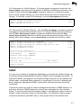
Filter Control
The wireless bridge can employ VLAN tagging support and network traffic frame
filtering to control access to network resources and increase security.
Native VLAN ID – The VLAN ID used to tag traffic passing from the wireless
interface to the wired network. (Range: 1-64)
VLAN – Enables or disables VLAN tagging support on the wireless bridge (changing
the VLAN status forces a system reboot). When VLAN support is enabled, the
wireless bridge tags traffic passing to the wired network with the assigned native
VLAN ID (a number between 1 and 64). Traffic received from the wired network
must also be tagged with the same VLAN ID. Received traffic that has an unknown
VLAN ID or no VLAN tag is dropped. When VLAN support is disabled, the wireless
bridge does not tag traffic passing to the wired network and ignores the VLAN tags
on any received frames.
Note: Before enabling VLANs on the wireless bridge, you must configure the connected
LAN switch port to accept tagged VLAN packets with the wireless bridge’s native
VLAN ID. Otherwise, connectivity to the wireless bridge will be lost when you
enable the VLAN feature.
Ethernet Type Filter – Controls checks on the Ethernet type of all incoming and
outgoing Ethernet packets against the protocol filtering table.
• Disable: Wireless bridge does not filter Ethernet protocol types.
• Enable: Wireless bridge filters Ethernet protocol types based on the configuration
of protocol types in the filter table. If a protocol has its status set to “ON,” the
protocol is filtered from the wireless bridge.
5-6
5
Advanced Configuration
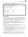
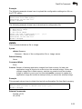
CLI Commands for VLAN Support – From the global configuration mode use the
native-vlanid command to set the default VLAN ID for the Ethernet interface, then
enable VLANs using the vlan enable command. When you change the access
point’s VLAN support setting, you must reboot the access point to implement the
change. To view the current VLAN settings, use the show system command.
Outdoor Bridge(config)#native-vlanid 3
Outdoor Bridge(config)#vlan enable
Reboot system now? <y/n>: y
6-59
6-58
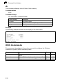
CLI Commands for Bridge Filtering – Use the filter ap-manage command to restrict
management access from wireless clients. To configure Ethernet protocol filtering,
use the filter ethernet-type enable command to enable filtering and the filter
ethernet-type protocol command to define the protocols that you want to filter. To
display the current settings, use the show filters command from the Exec mode.
Outdoor
Outdoor
Outdoor
Outdoor
Outdoor
Bridge(config)#filter ap-manage
Bridge(config)#filter ethernet-type enable
Bridge(config)#filter ethernet-type protocol ARP
Bridge(config)#exit
Bridge#show filters
6-40
6-41
6-41
6-42
Protocol Filter Information
=========================================================
AP Management
:ENABLED
Ethernet Type Filter :ENABLED
Enabled Protocol Filters
--------------------------------------------------------Protocol: ARP
ISO: 0x0806
=========================================================
Outdoor Bridge#
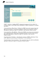
SNMP
You can use a network management application to manage the wireless bridge via
the Simple Network Management Protocol (SNMP) from a management station. To
implement SNMP management, the wireless bridge must have an IP address and
subnet mask, configured either manually or dynamically. Once an IP address has
been configured, appropriate SNMP communities and trap receivers should be
configured.
Community names are used to control management access to SNMP stations, as
well as to authorize SNMP stations to receive trap messages from the wireless
bridge. To communicate with the wireless bridge, a management station must first
submit a valid community name for authentication. You therefore need to assign
community names to specified users or user groups and set the access level.
5-7
5
System Configuration
SNMP – Enables or disables SNMP management access and also enables the
wireless bridge to send SNMP traps (notifications). SNMP management is enabled
by default.
Community Name (Read Only) – Defines the SNMP community access string that
has read-only access. Authorized management stations are only able to retrieve
MIB objects. (Maximum length: 23 characters, case sensitive; Default: public)
Community Name (Read/Write) – Defines the SNMP community access string that
has read/write access. Authorized management stations are able to both retrieve
and modify MIB objects. (Maximum length: 23 characters, case sensitive;
Default: private)
Trap Destination IP Address – Specifies the recipient of SNMP notifications. Enter
the IP address or the host name. (Host Name: 1 to 20 characters)
Trap Destination Community Name – The community string sent with the notification
operation. (Maximum length: 23 characters; Default: public)
5-8
5
Advanced Configuration
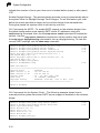
CLI Commands for SNMP – Use the snmp-server enable server command from the
global configuration mode to enable SNMP. To set read/write and read-only
community names, use the snmp-server community command. The snmp-server
host command defines a trap receiver host. To view the current SNMP settings, use
the show snmp command.
Outdoor
Outdoor
Outdoor
Outdoor
Outdoor
Outdoor
Bridge(config)#snmp-server
Bridge(config)#snmp-server
Bridge(config)#snmp-server
Bridge(config)#snmp-server
Bridge(config)#exit
Bridge#show snmp
enable server
community alpha rw
community beta ro
host 10.1.19.23 alpha
6-25
6-23
6-25
6-26
SNMP Information
============================================
Service State : Enable
Community (ro) : ****
Community (rw) : *****
Location
: building-1
Contact
: Paul
Traps
: Enabled
Host Name/IP
: 10.1.19.23
Trap Community : *****
=============================================
Outdoor Bridge#
5-9
5
System Configuration
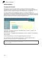
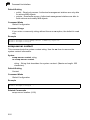
Administration
Changing the Password
Management access to the web and CLI interface on the wireless bridge is
controlled through a single user name and password. You can also gain additional
access security by using control filters (see “Filter Control” on page 5-6).
To protect access to the management interface, you need to configure an
Administrator’s user name and password as soon as possible. If the user name and
password are not configured, then anyone having access to the wireless bridge may
be able to compromise wireless bridge and network security.
Username – The name of the user. The default name is “admin.” (Length: 3-16
characters, case sensitive.)
New Password – The password for management access. (Length: 3-16 characters,
case sensitive)
Confirm New Password – Enter the password again for verification.
CLI Commands for the User Name and Password – Use the username and
password commands from the CLI configuration mode.
Outdoor Bridge(config)#username bob
Outdoor Bridge(config)#password spiderman
Outdoor Bridge#
5-10
6-13
6-13
Advanced Configuration
5
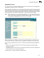
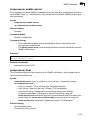
Upgrading Firmware
You can upgrade new wireless bridge software from a local file on the management
workstation, or from an FTP or TFTP server.
After upgrading new software, you must reboot the wireless bridge to implement the
new code. Until a reboot occurs, the wireless bridge will continue to run the software
it was using before the upgrade started. Also note that rebooting the wireless bridge
with new software will reset the configuration to the factory default settings.
Note: Before upgrading your wireless bridge software, it is recommended to save a
copy of the current configuration file. See “copy” on page 6-28 for information
on saving the configuration file to a TFTP or FTP server.
Before upgrading new software, verify that the wireless bridge is connected to the
network and has been configured with a compatible IP address and subnet mask.
If you need to download from an FTP or TFTP server, take the following additional
steps:
• Obtain the IP address of the FTP or TFTP server where the wireless bridge
software is stored.
• If upgrading from an FTP server, be sure that you have an account configured on
the server with a user name and password.
Current version – Version number of runtime code.
5-11
5
System Configuration
Firmware Upgrade Local – Downloads an operation code image file from the web
management station to the wireless bridge using HTTP. Use the Browse button to
locate the image file locally on the management station and click Start Upgrade to
proceed.
• New firmware file: Specifies the name of the code file on the server. The new
firmware file name should not contain slashes (\ or /), the leading letter of the file
name should not be a period (.), and the maximum length for file names is 32
characters for files on the wireless bridge. (Valid characters: A-Z, a-z, 0-9, “.”, “-”,
“_”)
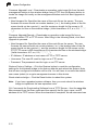
Firmware Upgrade Remote – Downloads an operation code image file from a
specified remote FTP or TFTP server. After filling in the following fields, click Start
Upgrade to proceed.
• New firmware file: Specifies the name of the code file on the server. The new
firmware file name should not contain slashes (\ or /), the leading letter of the file
name should not be a period (.), and the maximum length for file names on the
FTP/TFTP server is 255 characters or 32 characters for files on the wireless bridge.
(Valid characters: A-Z, a-z, 0-9, “.”, “-”, “_”)
• IP Address: IP address or host name of FTP or TFTP server.
• Username: The user ID used for login on an FTP server.
• Password: The password used for login on an FTP server.
Restore Factory Settings – Click the Restore button to reset the configuration
settings for the wireless bridge to the factory defaults and reboot the system. Note
that all user configured information will be lost. You will have to re-enter the default
user name (admin) to re-gain management access to this device.
Reset wireless bridge – Click the Reset button to reboot the system.
Note: If you have upgraded system software, then you must reboot the wireless
bridge to implement the new operation code.
CLI Commands for Downloading Software from a TFTP Server – Use the copy tftp
file command from the Exec mode and then specify the file type, name, and IP
address of the TFTP server. When the download is complete, the dir command can
5-12
5
Advanced Configuration
be used to check that the new file is present in the wireless bridge file system. To run
the new software, use the reset board command to reboot the wireless bridge.
Outdoor Bridge#copy tftp file
1. Application image
2. Config file
3. Boot block image
Select the type of download<1,2,3>: [1]:1
TFTP Source file name:bridge-img.bin
TFTP Server IP:192.168.1.19
6-28
Outdoor Bridge#dir
File Name
-------------------------dflt-img.bin
bridge-img.bin
syscfg
syscfg_bak
6-30
Type
---2
2
5
5
File Size
----------1319939
1629577
17776
17776
262144 byte(s) available
Outdoor Bridge#reset board
Reboot system now? <y/n>: y
6-9
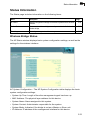
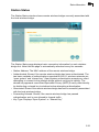
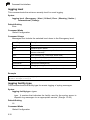
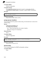
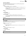
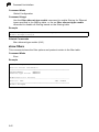
System Log
The wireless bridge can be configured to send event and error messages to a
System Log Server. The system clock can also be synchronized with a time server,
so that all the messages sent to the Syslog server are stamped with the correct time
and date.
5-13
5
System Configuration
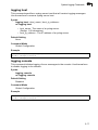
Enabling System Logging
The wireless bridge supports a logging process that can control error messages
saved to memory or sent to a Syslog server. The logged messages serve as a
valuable tool for isolating wireless bridge and network problems.
System Log Setup – Enables the logging of error messages.
Logging Host – Enables the sending of log messages to a Syslog server host.
Server Name/IP – The IP address or name of a Syslog server.
Logging Console – Enables the logging of error messages to the console.
Logging Level – Sets the minimum severity level for event logging.
The system allows you to limit the messages that are logged by specifying a
minimum severity level. The following table lists the error message levels from the
most severe (Emergency) to least severe (Debug). The message levels that are
logged include the specified minimum level up to the Emergency level.
Error Level
Description
Emergency
System unusable
Alert
Immediate action needed
Critical
Critical conditions (e.g., memory allocation, or free memory error - resource
exhausted)
Error
Error conditions (e.g., invalid input, default used)
Warning
Warning conditions (e.g., return false, unexpected return)
Notice
Normal but significant condition, such as cold start
Informational
Informational messages only
Debug
Debugging messages
Note: The wireless bridge error log can be viewed using the Event Logs window in
the Status section (page 5-36).The Event Logs window displays the last 128
messages logged in chronological order, from the newest to the oldest. Log
messages saved in the wireless bridge’s memory are erased when the
device is rebooted.
CLI Commands for System Logging – To enable logging on the wireless bridge, use
the logging on command from the global configuration mode. The logging level
command sets the minimum level of message to log. Use the logging console
command to enable logging to the console. Use the logging host command to
specify up to four Syslog servers. The CLI also allows the logging facility-type
5-14
5
Advanced Configuration
command to set the facility-type number to use on the Syslog server. To view the
current logging settings, use the show logging command.
Outdoor
Outdoor
Outdoor
Outdoor
Outdoor
Outdoor
Outdoor
Bridge(config)#logging
Bridge(config)#logging
Bridge(config)#logging
Bridge(config)#logging
Bridge(config)#logging
Bridge(config)#exit
Bridge#show logging
on
level alert
console
host 1 10.1.0.3 514
facility-type 19
6-16
6-18
6-17
6-17
6-18
6-19
Logging Information
============================================
Syslog State
: Enabled
Logging Host State
: Enabled
Logging Console State
: Enabled
Server Domain name/IP
: 1 10.1.0.3
Logging Level
: Error
Logging Facility Type
: 16
=============================================
Outdoor Bridge#
Configuring SNTP
Simple Network Time Protocol (SNTP) allows the wireless bridge to set its internal
clock based on periodic updates from a time server (SNTP or NTP). Maintaining an
accurate time on the wireless bridge enables the system log to record meaningful
dates and times for event entries. If the clock is not set, the wireless bridge will only
record the time from the factory default set at the last bootup.
The wireless bridge acts as an SNTP client, periodically sending time
synchronization requests to specific time servers. You can configure up to two time
server IP addresses. The wireless bridge will attempt to poll each server in the
configured sequence.
SNTP Server – Configures the wireless bridge to operate as an SNTP client. When
enabled, at least one time server IP address must be specified.
• Primary Server: The IP address of an SNTP or NTP time server that the wireless
bridge attempts to poll for a time update.
• Secondary Server: The IP address of a secondary SNTP or NTP time server. The
wireless bridge first attempts to update the time from the primary server; if this fails
it attempts an update from the secondary server.
Note: The wireless bridge also allows you to disable SNTP and set the system
clock manually using the CLI.
Set Time Zone – SNTP uses Coordinated Universal Time (or UTC, formerly
Greenwich Mean Time, or GMT) based on the time at the Earth’s prime meridian,
zero degrees longitude. To display a time corresponding to your local time, you must
5-15
5
System Configuration
indicate the number of hours your time zone is located before (east) or after (west)
UTC.
Enable Daylight Saving – The wireless bridge provides a way to automatically adjust
the system clock for Daylight Savings Time changes. To use this feature you must
define the month and date to begin and to end the change from standard time.
During this period the system clock is set back by one hour.
CLI Commands for SNTP – To enable SNTP support on the wireless bridge, from
the global configuration mode specify SNTP server IP addresses using the
sntp-server ip command, then use the sntp-server enable command to enable the
service. Use the sntp-server timezone command to set the location time zone and
the sntp-server daylight-saving command to set up a daylight saving. To view the
current SNTP settings, use the show sntp command.
Outdoor Bridge(config)#sntp-server ip 10.1.0.19
Outdoor Bridge(config)#sntp-server enable
Outdoor Bridge(config)#sntp-server timezone +8
Outdoor Bridge(config)#sntp-server daylight-saving
Enter Daylight saving from which month<1-12>: 3
and which day<1-31>: 31
Enter Daylight saving end to which month<1-12>: 10
and which day<1-31>: 31
Outdoor Bridge(config)#exit
Outdoor Bridge#show sntp
6-20
6-20
6-22
6-21
6-22
SNTP Information
=========================================================
Service State
: Enabled
SNTP (server 1) IP
: 137.92.140.80
SNTP (server 2) IP
: 192.43.244.18
Current Time
: 19 : 35, Oct 10th, 2003
Time Zone
: +8 (TAIPEI, BEIJING)
Daylight Saving
: Enabled, from Mar, 31th to Oct, 31th
=========================================================
Outdoor Bridge#
CLI Commands for the System Clock – The following example shows how to
manually set the system time when SNTP server support is disabled on the wireless
bridge.
Outdoor Bridge(config)#no sntp-server enable
Outdoor Bridge(config)#sntp-server date-time
Enter Year<1970-2100>: 2003
Enter Month<1-12>: 10
Enter Day<1-31>: 10
Enter Hour<0-23>: 18
Enter Min<0-59>: 35
Outdoor Bridge(config)#
5-16
6-20
6-21
Advanced Configuration
5
Wireless Distribution System (WDS)
The IEEE 802.11a standard defines a WIreless Distribution System (WDS) for
connections between wireless bridges. The outdoor wireless bridge uses WDS to
forward traffic on links between units. When using WDS, only wireless bridge units
can associate to each other. A wireless client cannot associate with any unit in a
wireless bridge network.
To set up a wireless bridge link you must configure the WDS forwarding table by
specifying the wireless MAC address of the bridge to which you want to forward
traffic. For a Slave bridge unit, you need to specify the MAC address of the wireless
bridge unit at the opposite end of the link. For a Master bridge unit, you need to
specify the MAC addresses of all the Slave bridge units in the network.
Mode – The wireless bridge software operates in a Slave or Master mode depending
on the unit hardware (the mode is not configurable):
• Master Mode: In a point-to-multipoint network configuration, only one wireless
bridge unit must be a Master unit (all others must be Slave units). A Master wireless
bridge provides support for up to 16 MAC addresses in the WDS forwarding table.
The MAC addresses of all other Slave bridge units in the network must be
configured in the forwarding table.
• Slave Mode: A Slave wireless bridge provides support for only one MAC address
in the WDS forwarding table. A Slave bridge communicates with only one other
wireless bridge, either another Slave bridge in a point-to-point configuration, or to
the Master bridge in a point-to-multipoint configuration.
Port No (Master bridge only) – The wireless port identifier (1 to 16).
5-17
5
System Configuration
MAC Address – The physical layer address of the wireless bridge unit at the other
end of the wireless link. (12 hexadecimal digits in the form “xx:xx:xx:xx:xx:xx”)
Port Status – Enables or disables the wireless bridge link.
Note: The wireless MAC address for each bridge unit is printed on the label on the
back of the unit.
CLI Commands for WDS – The following example shows how to configure the MAC
address of the wireless bridge at the opposite end of a point-to-point link, and then
enable forwarding on the link.
Outdoor
Outdoor
Outdoor
Outdoor
Bridge(config)#wds mac-address 1 00-12-34-56-78-9a
Bridge(config)#wds enable
Bridge(config)#exit
Bridge#show wds
6-31
6-31
6-32
Outdoor_Mode
:
SLAVE
==================================================
Port ID |
Status
|
Mac-Address
==================================================
01
|
ENABLE
|
00-12-34-56-78-9A
==================================================
Outdoor Bridge#
Bridge
The wireless bridge can store the MAC addresses for all known devices in the
connected networks. All the addresses are learned by monitoring traffic received by
the wireless bridge and are stored in a dynamic MAC address table. This information
is then used to forward traffic directly between the Ethernet port and the wireless
interface.
The Bridging page allows the MAC address aging time to be set for both the
Ethernet port and the wireless radio interface. If the MAC address of an entry in the
address table is not seen on the associated interface for longer than the aging time,
the entry is discarded.
5-18
Advanced Configuration
5
Bridge Aging Time – Changes the aging time for entries in the dynamic address
table:
• Ethernet: The time after which a learned Ethernet port entry is discarded. (Range:
60-1800 seconds; Default: 100 seconds)
• Wireless 802.11a: The time after which a learned wireless entry is discarded.
(Range: 60-1800 seconds; Default: 1800 seconds)
5-19
5
System Configuration
CLI Commands for Bridging – The following example shows how to set the MAC
address aging time for the wireless bridge.
Outdoor
Outdoor
Outdoor
Outdoor
Bridge(config)#bridge timeout 0 300
Bridge(config)#bridge timeout 2 1000
Bridge(config)#exit
Bridge#show bridge
6-33
6-33
6-39
Bridge Information
=================================================
Media Type | Age Time(sec)|
=================================================
EtherNet |
300
|
WLAN_A
| 1000
|
==================================================
Bridge Id
: 32768.037fbef192
Root Bridge Id
: 32768.01f47483e2
Root Path Cost
: 25
Root Port Id
: 0
Bridge Status
: Enabled
Bridge Priority
: 32768
Bridge Hello Time
: 2 Seconds
Bridge Maximum Age : 20 Seconds
Bridge Forward Delay: 15 Seconds
============================= Port Summary =============================
Id| Priority | Path Cost | Fast Forward | Status |
State
|
0
128
25
Enable
Enabled
Forwarding
Outdoor Bridge#
5-20
5
Advanced Configuration
Spanning Tree Protocol (STP)
The Spanning Tree Protocol (STP) can be used to detect and disable network loops,
and to provide backup links between switches, bridges or routers. This allows the
wireless bridge to interact with other bridging devices (that is, an STP-compliant
switch, bridge or router) in your network to ensure that only one route exists between
any two stations on the network, and provide backup links which automatically take
over when a primary link goes down.
STP uses a distributed algorithm to select a bridging device (STP-compliant switch,
bridge or router) that serves as the root of the spanning tree network. It selects a
root port on each bridging device (except for the root device) which incurs the lowest
path cost when forwarding a packet from that device to the root device. Then it
selects a designated bridging device from each LAN which incurs the lowest path
cost when forwarding a packet from that LAN to the root device. All ports connected
to designated bridging devices are assigned as designated ports. After determining
the lowest cost spanning tree, it enables all root ports and designated ports, and
disables all other ports. Network packets are therefore only forwarded between root
ports and designated ports, eliminating any possible network loops.
Once a stable network topology has been established, all bridges listen for Hello
BPDUs (Bridge Protocol Data Units) transmitted from the root bridge. If a bridge
does not get a Hello BPDU after a predefined interval (Maximum Age), the bridge
assumes that the link to the root bridge is down. This bridge will then initiate
negotiations with other bridges to reconfigure the network to reestablish a valid
network topology.
Enable – Enables/disables STP on the wireless bridge. (Default: Enable)
5-21
5
System Configuration
Forward Delay – The maximum time (in seconds) this device waits before changing
states (i.e., discarding to learning to forwarding). This delay is required because
every device must receive information about topology changes before it starts to
forward frames. In addition, each port needs time to listen for conflicting information
that would make it return to a discarding state; otherwise, temporary data loops
might result. (Range: 4-30 seconds)
• Default: 15
• Minimum: The higher of 4 or [(Max. Message Age / 2) + 1]
• Maximum: 30
Hello Time – Interval (in seconds) at which the root device transmits a configuration
message. (Range: 1-10 seconds)
• Default: 2
• Minimum: 1
• Maximum: The lower of 10 or [(Max. Message Age / 2) -1]
Maximum Age – The maximum time (in seconds) a device can wait without receiving
a configuration message before attempting to reconfigure. All device ports (except
for designated ports) should receive configuration messages at regular intervals.
Any port that ages out STP information (provided in the last configuration message)
becomes the designated port for the attached LAN. If it is a root port, a new root port
is selected from among the device ports attached to the network. (Range: 6-40
seconds)
• Default: 20
• Minimum: The higher of 6 or [2 x (Hello Time + 1)].
• Maximum: The lower of 40 or [2 x (Forward Delay - 1)]
Bridge Priority – Used in selecting the root device, root port, and designated port.
The device with the highest priority becomes the STP root device. However, if all
devices have the same priority, the device with the lowest MAC address will then
become the root device. (Note that lower numeric values indicate higher priority.)
• Range: 0-65535
• Default: 32768
Port Cost – This parameter is used by the STP to determine the best path between
devices. Therefore, lower values should be assigned to ports attached to faster
media, and higher values assigned to ports with slower media. (Path cost takes
precedence over port priority.)
• Range: 1-65535
• Default: Ethernet interface: 19; Wireless interface: 40
5-22
Advanced Configuration
5
Priority – Defines the priority used for this port in the Spanning Tree Protocol. If the
path cost for all ports on a switch are the same, the port with the highest priority (i.e.,
lowest value) will be configured as an active link in the spanning tree. This makes a
port with higher priority less likely to be blocked if the Spanning Tree Protocol is
detecting network loops. Where more than one port is assigned the highest priority,
the port with lowest numeric identifier will be enabled.
• Default: 128
• Range: 0-240, in steps of 16
Port Fast (Fast Forwarding) – You can enable this option if an interface is attached
to a LAN segment that is at the end of a bridged LAN or to an end node. Since end
nodes cannot cause forwarding loops, they can pass directly through to the
spanning tree forwarding state. Specifying fast forwarding provides quicker
convergence for devices such as workstations or servers, retains the current
forwarding database to reduce the amount of frame flooding required to rebuild
address tables during reconfiguration events, does not cause the spanning tree to
initiate reconfiguration when the interface changes state, and also overcomes other
STP-related timeout problems. However, remember that fast forwarding should only
be enabled for ports connected to an end-node device. (Default: Disable)
Status – Enables/disables STP on this interface. (Default: Enable)
5-23
5
System Configuration
CLI Commands for STP – The following example configures spanning tree
paramters for the bridge and wireless port 5.
Outdoor
Outdoor
Outdoor
Outdoor
Outdoor
Outdoor
Outdoor
Outdoor
Outdoor
Outdoor
Bridge(config)#bridge stp-bridge priority 40000
Bridge(config)#bridge stp-bridge hello-time 5
Bridge(config)#bridge stp-bridge max-age 38
Bridge(config)#bridge stp-bridge forward-time 20
Bridge(config)#no bridge stp-port spanning-disabled 5
Bridge(config)#bridge stp-port priority 5 0
Bridge(config)#bridge stp-port path-cost 5 50
Bridge(config)#no bridge stp-port portfast 5
Bridge(config)#end
Bridge#show bridge
6-36
6-35
6-35
6-34
6-39
6-37
6-37
6-38
6-39
Bridge Information
=================================================
Media Type | Age Time(sec)|
=================================================
EtherNet |
300
|
WLAN_A
| 1000
|
==================================================
Bridge Id
: 32768.037fbef192
Root Bridge Id
: 32768.01f47483e2
Root Path Cost
: 25
Root Port Id
: 0
Bridge Status
: Enabled
Bridge Priority
: 40000
Bridge Hello Time
: 5 Seconds
Bridge Maximum Age : 38 Seconds
Bridge Forward Delay: 20 Seconds
============================= Port Summary =============================
Id| Priority | Path Cost | Fast Forward | Status |
State
|
0
128
25
Enable
Enabled
Forwarding
Outdoor Bridge#
5-24
5
Radio Interface
Radio Interface
The IEEE 802.11a radio interface includes configuration options for radio signal
characteristics and wireless security features.
Note: The radio channel settings for the wireless bridge are limited by local
regulations, which determine the number of channels that are available.
Radio Settings (802.11a)
The IEEE 802.11a interface operates within the 5 GHz band, at up to 54 Mbps in
normal mode or up to 108 Mbps in Turbo mode.
Enable – Enables radio communications on the wireless bridge. (Default: Enable)
Description – Adds a comment or description to the wireless interface. (Range: 1-80
characters)
Secure Access – When enabled, the bridge radio does not include its SSID in
beacon messages. Nor does it respond to probe requests from other bridges that do
not include a fixed SSID. (Default: Enable)
Turbo Mode – The normal 802.11a wireless operation mode provides connections
up to 54 Mbps. Turbo Mode is an enhanced mode (not regulated in IEEE 802.11a)
that provides a higher data rate of up to 108 Mbps. Enabling Turbo Mode allows the
wireless bridge to provide connections up to 108 Mbps. (Default: Disable)
5-25
5
System Configuration
Note: In normal mode, the wireless bridge provides a channel bandwidth of
20 MHz, and supports the maximum number of channels permitted by local
regulations (e.g., 11 channels for the United States). In Turbo Mode, the
channel bandwidth is increased to 40 MHz to support the increased data
rate. However, this reduces the number of channels supported (e.g., 5
channels for the United States).
Radio Channel – The radio channel that the wireless bridge
Normal Mode
uses to communicate with wireless clients. When multiple
wireless bridges are deployed in the same area, set the
channel on neighboring wireless bridges at least four channels
apart to avoid interference with each other. For example, in the
United States you can deploy up to four wireless bridges in the
same area (e.g., channels 36, 56, 149, 165). Also note that the
channel for wireless clients is automatically set to the same as
that used by the wireless bridge to which it is linked. (Default:
Channel 60 for normal mode, and channel 42 for Turbo mode)
Transmit Power – Adjusts the power of the radio signals
transmitted from the wireless bridge. The higher the
transmission power, the farther the transmission range. Power Turbo Mode
selection is not just a trade off between coverage area and
maximum supported clients. You also have to ensure that
high-power signals do not interfere with the operation of other
radio devices in the service area. (Options: 100%, 50%, 25%,
12%, minimum (6.25%); Default: 100%)
Actual transmit power depends on the antenna, radio
channel, and transmit data rate. See “Antenna Specifications” on page B-3 for
details on maximum output power for specific antennas. The maximum transmit
power may also be lowered by local regulatory limits.
Maximum Supported Rate – The maximum data rate at which a client can connect to
the wireless bridge. The maximum transmission distance is affected by the data
rate. The lower the data rate, the longer the transmission distance.
(Options: 54, 48, 36, 24, 18, 12, 9, 6 Mbps; Default: 54 Mbps)
Beacon Interval – The rate at which beacon signals are transmitted from the
wireless bridge. The beacon signals allow wireless clients to maintain contact with
the wireless bridge. They may also carry power-management information.
(Range: 20-1000 TUs; Default: 100 TUs; where one Time Unit (TU) is 1024
microseconds)
Data Beacon Rate – The rate at which stations in sleep mode must wake up to
receive broadcast/multicast transmissions.
Known also as the Delivery Traffic Indication Map (DTIM) interval, it indicates how
often the MAC layer forwards broadcast/multicast traffic, which is necessary to wake
up stations that are using Power Save mode. The default value of 2 indicates that
5-26
5
Radio Interface
the wireless bridge will save all broadcast/multicast frames for the Basic Service Set
(BSS) and forward them after every second beacon. Using smaller DTIM intervals
delivers broadcast/multicast frames in a more timely manner, causing stations in
Power Save mode to wake up more often and drain power faster. Using higher DTIM
values reduces the power used by stations in Power Save mode, but delays the
transmission of broadcast/multicast frames.
(Range: 1-255 beacons; Default: 2 beacons)
RTS Threshold – Sets the packet size threshold at which a Request to Send (RTS)
signal must be sent to a receiving station prior to the sending station starting
communications. The wireless bridge sends RTS frames to a receiving station to
negotiate the sending of a data frame. After receiving an RTS frame, the station
sends a CTS (clear to send) frame to notify the sending station that it can start
sending data.
If the RTS threshold is set to 0, the wireless bridge never sends RTS signals. If set
to 2347, the wireless bridge always sends RTS signals. If set to any other value, and
the packet size equals or exceeds the RTS threshold, the RTS/CTS (Request to
Send / Clear to Send) mechanism will be enabled.
The wireless bridges contending for the medium may not be aware of each other.
The RTS/CTS mechanism can solve this “Hidden Node Problem.” (Range: 0-2347
bytes: Default: 2347 bytes)
CLI Commands for the 802.11a Wireless Interface – From the global configuration
mode, enter the interface wireless a command to access the 802.11a radio
interface. If required, configure a name for the interface using the description
command. Use the turbo command to enable this feature before setting the radio
channel with the channel command. Set any other parameters as required. To view
the current 802.11a radio settings, use the show interface wireless a command.
Outdoor Bridge(config)#interface wireless a
Enter Wireless configuration commands, one per line.
Outdoor Bridge(if-wireless a)#description RD-AP#3
Outdoor Bridge(if-wireless a)#turbo
Outdoor Bridge(if-wireless a)#channel 42
Outdoor Bridge(if-wireless a)#transmit-power full
Outdoor Bridge(if-wireless a)#speed 9
Outdoor Bridge(if-wireless a)#beacon-interval 150
Outdoor Bridge(if-wireless a)#dtim-period 5
Outdoor Bridge(if-wireless a)#fragmentation-length 512
Outdoor Bridge(if-wireless a)#rts-threshold 256
Outdoor Bridge(if-wireless a)#
6-43
6-48
6-50
6-49
6-56
6-49
6-50
6-51
6-52
6-52
5-27
5
System Configuration
Outdoor Bridge#show interface wireless a
6-57
Wireless Interface 802.11a Information
==========================================================
----------------Identification---------------------------Description
: 802.11a wireless bridge
Turbo Mode
: ON
Channel
: 42 (AUTO)
Status
: Enable
----------------802.11 Parameters------------------------Transmit Power
: FULL (17 dBm)
Max Station Data Rate
: 9Mbps
Fragmentation Threshold
: 512 bytes
RTS Threshold
: 256 bytes
Beacon Interval
: 150 TUs
DTIM Interval
: 5 beacons
----------------Security---------------------------------Encryption
: DISABLED
Default Transmit Key
: 1
Static Keys :
Key 1: EMPTY
Key 2: EMPTY
Key 3: EMPTY
Key 4: EMPTY
==========================================================
Outdoor Bridge#
Security
Wired Equivalent Privacy (WEP) and Advanced Encryption Standard (AES) are
implemented in the wireless bridge to prevent unauthorized access to network data.
For more secure data transmissions, enable WEP or AES encryption for the
wireless bridge and set at least one encryption key.
Wired Equivalent Privacy (WEP)
WEP provides a basic level of security, preventing unauthorized access to the
network and encrypting data transmitted between wireless bridge units. WEP uses
static shared keys (fixed-length hexadecimal or alphanumeric strings) that are
manually configured on all bridges in the wireless bridge network.
5-28
5
Radio Interface
Setting up IEEE 802.11 Wired Equivalent Privacy (WEP) shared keys enables the
wireless bridge to prevent unauthorized access to the network.
Be sure to define at least one static WEP key for data encryption. Also, be sure that
the WEP keys are the same for all bridge units in the wireless network.
Data Encryption Setup – Enable or disable the wireless bridge to use either WEP or
AES for data encryption. If WEP encryption is selected and enabled, you must
configure at least one encryption key on the wireless bridge. (Default: Disable)
Shared Key Setup – Select 64 Bit, 128 Bit, or 152 Bit key length. Note that the same
size of WEP encryption key must be set on all bridge units in the wireless network.
(Default: 128 Bit)
Key Type – Select the preferred method of entering WEP encryption keys on the
wireless bridge and enter up to four keys:
• Hexadecimal: Enter keys as 10 hexadecimal digits (0 to 9 and A to F) for 64 bit
keys, 26 hexadecimal digits for 128 bit keys, or 32 hexadecimal digits for 152 bit
keys.
• Alphanumeric: Enter keys as 5 alphanumeric characters for 64 bit keys, 13
alphanumeric characters for 128 bit keys, or 16 alphanumeric characters for 152
bit keys.
• Transmit Key Select: Selects the key number to use for encryption. Bridge units in
the wireless network must have all four keys configured to the same values.
Note: Key index and type must match on all bridge units in the wireless network.
5-29
5
System Configuration
Advanced Encryption Standard (AES)
AES has been designated by the National Institute of Standards and Technology as
the successor to the Data Encryption Standard (DES) encryption algorithm, and will
be used by the U.S. government for encrypting all sensitive, nonclassified
information. Because of its strength, and resistance to attack, AES is also being
incorporated as part of the 802.11 security standard.
The wireless bridge uses 128-bit static AES keys (hexadecimal or alphanumeric
strings) that are configured for each link pair in the wireless bridge network. For a
Slave bridge unit, only one encryption key needs to be defined. A Master bridge
allows a different key to be defined for each wireless bridge link in the network.
Configuring AES encryption keys on the wireless bridge provides far more robust
security than using WEP. Also, a unique AES key can be used for each bridge link in
the wireless network, instead of all bridges sharing the same WEP keys.
Data Encryption Setup – Enable or disable the wireless bridge to use either WEP or
AES for data encryption. If AES encryption is selected and enabled, you must
configure one encryption key for each wireless port link on the wireless bridge. A
Slave bridge supports only one wireless port link, but a Master bridge supports up to
16 links. (Default: Disable)
Key Type – Select the preferred method of entering AES encryption keys on the
wireless bridge and enter a key for each bridge link in the network:
• Hexadecimal: Enter keys as exactly 32 hexadecimal digits (0 to 9 and A to F).
5-30
5
Radio Interface
• Alphanumeric: Enter keys as an alphanumeric string using between 8 and 31
characters.
Note: For each wireless port link (1 to 16), the AES keys must match on the
corresponding bridge unit.
CLI Commands for WEP Security – From the 802.11a interface configuration mode,
use the encryption command to enable WEP encryption. To enter WEP keys, use the
key command, and then set one key as the transmit key using the transmit-key
command. To view the current security settings, use the show interface wireless a
command.
Outdoor Bridge(config)#interface wireless a
Enter Wireless configuration commands, one per line.
Outdoor Bridge(if-wireless a)#encryption wep 128
Outdoor Bridge(if-wireless a)#key wep 1 128 ascii abcdeabcdeabc
Outdoor Bridge(if-wireless a)#transmit-key 1
Outdoor Bridge(if-wireless a)#exit
Outdoor Bridge#show interface wireless a
Wireless Interface 802.11g Information
==========================================================
Description
: Enterprise 802.11a Access Point
Turbo Mode
: OFF
Channel
: 36
Status
: Disable
Service type
: WDS
----------------802.11 Parameters-------------------------Transmit Power
: FULL (15 dBm)
Max Station Data Rate
: 54Mbps
Fragmentation Threshold
: 2346 bytes
RTS Threshold
: 2347 bytes
Beacon Interval
: 100 TUs
DTIM Interval
: 2 beacons
----------------Security----------------------------------Encryption
: 128-BIT WEP ENCRYPTION
WEP Key type
: Alphanumeric
Default Transmit Key
: 1
Static Keys :
Key 1: *****
Key 2: EMPTY
Key 3: EMPTY
Key 4: EMPTY
===========================================================
Outdoor Bridge#
6-43
6-53
6-54
6-55
6-57
Note: The index and length values used in the key command must be the same
values used in the encryption and transmit-key commands.
5-31
5
System Configuration
CLI Commands for AES Security – From the 802.11a interface configuration mode,
use the encryption command to enable AES encryption. To enter AES keys, use the
key command. To view the current security settings, use the show interface wireless
a command.
Outdoor Bridge(config)#interface wireless a
Enter Wireless configuration commands, one per line.
Outdoor Bridge(if-wireless a)#encryption wdsaes alphanumeric
Outdoor Bridge(if-wireless a)#key wdsaes 1 agoodsecretkey
Outdoor Bridge(if-wireless a)#exit
Outdoor Bridge#show interface wireless a
Wireless Interface 802.11g Information
==========================================================
----------------Identification----------------------------Description
: Enterprise 802.11a Access Point
Turbo Mode
: OFF
Channel
: 36
Status
: Disable
Service type
: WDS
----------------802.11 Parameters-------------------------Transmit Power
: FULL (15 dBm)
Max Station Data Rate
: 54Mbps
Fragmentation Threshold
: 2346 bytes
RTS Threshold
: 2347 bytes
Beacon Interval
: 100 TUs
DTIM Interval
: 2 beacons
----------------Security----------------------------------Encryption
: 128-BIT AES ENCRYPTION
AES Key type
: Alphanumeric
===========================================================
Outdoor Bridge#
6-43
6-53
6-54
6-57
Note: The key type value entered using the key command must be the same as the
type specified in the encryption command.
5-32
Status Information
5
Status Information
The Status page includes information on the following items:
Menu
Description
Page
AP Status
Displays configuration settings for the basic system and the wireless
interface
5-33
Station Status
Shows remote wireless bridges currently associated with the local
wireless bridge
5-35
Event Logs
Shows log messages stored in memory
5-36
Wireless Bridge Status
The AP Status window displays basic system configuration settings, as well as the
settings for the wireless interface.
AP System Configuration – The AP System Configuration table displays the basic
system configuration settings:
• System Up Time: Length of time the management agent has been up.
• MAC Address: The physical layer address for this device.
• System Name: Name assigned to this system.
• System Contact: Administrator responsible for the system.
• System Mode: Indicates if the bridge is set as a Master or Slave unit.
• IP Address: IP address of the management interface for this device.
5-33
5
System Configuration
• IP Default Gateway: IP address of the gateway router between this device and
management stations that exist on other network segments.
• HTTP Server: Shows if management access via HTTP is enabled.
• HTTP Server Port: Shows the TCP port used by the HTTP interface.
• Version: Shows the version number for the runtime code.
AP Wireless Configuration – The AP Wireless Configuration table displays the
wireless interface settings listed below. Note that Radio A refers to the 802.11a
interface.
• Radio Channel: The radio channel currently used on the wireless bridge.
• Radio Encryption: The key size used for data encryption.
• Radio Authentication Type: Shows the bridge is set as an open system.
CLI Commands for Displaying System Settings – To view the current wireless bridge
system settings, use the show system command from the Exec mode. To view the
current radio interface settings, use the show interface wireless a command (see
page 6-57).
Outdoor Bridge#show system
System Information
==========================================================
Serial Number
: 0000000001
System Up time
: 0 days, 0 hours, 15 minutes, 30 seconds
System Name
: Outdoor Bridge
System Location
:
System Contact
: Contact
System Country Code : US - UNITED STATES
MAC Address
: 00-0D-3B-10-01-84
IP Address
: 192.168.1.1
Subnet Mask
: 255.255.255.0
Default Gateway
: 0.0.0.0
VLAN State
: DISABLED
Native VLAN ID
: 1
DHCP Client
: ENABLED
HTTP Server
: ENABLED
HTTP Server Port
: 80
Software Version
: v1.1.1.0
==========================================================
Outdoor Bridge#
5-34
6-15
Status Information
5
Station Status
The Station Status window shows remote wireless bridges currently associated with
the local wireless bridge.
The Station Status page displays basic connection information for each wireless
bridge link. Note that this page is automatically refreshed every five seconds.
• Station Address: The MAC address of the remote wireless bridge.
• Authenticated: Shows if the remote wireless bridge has been authenticated. The
two basic methods of authentication supported for 802.11 wireless networks are
“open system” and “shared key.” Open-system authentication accepts any client
attempting to connect to the wireless bridge without verifying its identity. The
shared-key approach uses Wired Equivalent Privacy (WEP) to verify client identity
by distributing a shared key to stations before attempting authentication.
• Associated: Shows if the remote wireless bridge has been successfully associated
with the local wireless bridge.
• Forwarding Allowed: Shows if the remote wireless bridge has passed
authentication and is now allowed to forward traffic.
• Key Type: Displays “Open System” or “Shared Key.”
5-35
5
System Configuration
Event Logs
The Event Logs window shows the log messages generated by the wireless bridge
and stored in memory.
The Event Logs table displays the following information:
• Log Time: The time the log message was generated.
• Event Level: The logging level associated with this message. For a description of
the various levels, see “logging level” on page 5-13.
• Event Message: The content of the log message.
CLI Commands for Displaying the Event Logs – From the global configuration mode,
use the show logging command.
Outdoor Bridge#show loggging
Logging Information
============================================
Syslog State
: Enabled
Logging Host State
: Enabled
Logging Console State
: Enabled
Server Domain name/IP
: 192.168.1.19
Logging Level
: Alert
Logging Facility Type
: 16
=============================================
Outdoor Bridge#
5-36
6-19
Chapter 6: Command Line Interface
Using the Command Line Interface
Accessing the CLI
When accessing the management interface for the wireless bridge via a Telnet
connection, the wireless bridge can be managed by entering command keywords
and parameters at the prompt. Using the wireless bridge’s command-line interface
(CLI) is very similar to entering commands on a UNIX system.
Telnet Connection
Telnet operates over the IP transport protocol. In this environment, your
management station and any network device you want to manage over the network
must have a valid IP address. Valid IP addresses consist of four decimal numbers, 0
to 255, separated by periods. Each address consists of a network portion and host
portion. For example, if the wireless bridge cannot acquire an IP address from a
DHCP server, the default IP address used by the wireless bridge, 192.168.1.1,
consists of a network portion (192.168.1) and a host portion (1).
To access the wireless bridge through a Telnet session, you must first set the IP
address for the wireless bridge, and set the default gateway if you are managing the
wireless bridge from a different IP subnet. For example:
Outdoor Bridge#configure
Outdoor Bridge(config)#interface ethernet
Outdoor Bridge(if-ethernet)#ip address 10.1.0.1 255.255.255.0
10.1.0.254
Outdoor Bridge(if-ethernet)#
After you configure the wireless bridge with an IP address, you can open a Telnet
session by performing these steps.
1.
From the remote host, enter the Telnet command and the IP address of the
device you want to access.
2.
At the prompt, enter the user name and system password. The CLI will display
the “Outdoor Bridge#” prompt to show that you are using executive access
mode (i.e., Exec).
3.
Enter the necessary commands to complete your desired tasks.
4.
When finished, exit the session with the “quit” or “exit” command.
After entering the Telnet command, the login screen displays:
Username: admin
Password:
Outdoor Bridge#
Note: You can open up to four sessions to the device via Telnet.
6-1
6
Command Line Interface
Entering Commands
This section describes how to enter CLI commands.
Keywords and Arguments
A CLI command is a series of keywords and arguments. Keywords identify a
command, and arguments specify configuration parameters. For example, in the
command “show interface ethernet,” show and interface are keywords, and
ethernet is an argument that specifies the interface type.
You can enter commands as follows:
• To enter a simple command, enter the command keyword.
• To enter commands that require parameters, enter the required parameters after
the command keyword. For example, to set a password for the administrator,
enter:
Outdoor Bridge(config)#username smith
Minimum Abbreviation
The CLI will accept a minimum number of characters that uniquely identify a
command. For example, the command “configure” can be entered as con. If an
entry is ambiguous, the system will prompt for further input.
Command Completion
If you terminate input with a Tab key, the CLI will print the remaining characters of a
partial keyword up to the point of ambiguity. In the “configure” example, typing con
followed by a tab will result in printing the command up to “configure.”
Getting Help on Commands
You can display a brief description of the help system by entering the help
command. You can also display command syntax by following a command with the
“?” character to list keywords or parameters.
Showing Commands
If you enter a “?” at the command prompt, the system will display the first level of
keywords for the current configuration mode (Exec, Global Configuration, or
6-2
Entering Commands
6
Interface). You can also display a list of valid keywords for a specific command. For
example, the command “show ?” displays a list of possible show commands:
Outdoor Bridge#show ?
bootfile
Show bootfile name
bridge
Show bridge table
filters
Show filters
hardware
Show hardware version
history
Display the session history
interface Show interface information
line
TTY line information
logging
Show the logging buffers
snmp
Show snmp statistics
sntp
Show sntp statistics
system
Show system information
version
Show system version
wds
Show wds table
Outdoor Bridge#show
The command “show interface ?” will display the following information:
Outdoor Bridge#show interface ?
ethernet Show Ethernet interface
wireless Show wireless interface
<cr>
Outdoor Bridge#show interface
Partial Keyword Lookup
If you terminate a partial keyword with a question mark, alternatives that match the
initial letters are provided. (Remember not to leave a space between the command
and question mark.) For example “s?” shows all the keywords starting with “s.”
Outdoor Bridge#show s?
snmp
sntp
system
Outdoor Bridge#show s
Negating the Effect of Commands
For many configuration commands you can enter the prefix keyword “no” to cancel
the effect of a command or reset the configuration to the default value. For example,
the logging command will log system messages to a host server. To disable
logging, specify the no logging command. This guide describes the negation effect
for all applicable commands.
Using Command History
The CLI maintains a history of commands that have been entered. You can scroll
back through the history of commands by pressing the up arrow key. Any command
displayed in the history list can be executed again, or first modified and then
executed.
Using the show history command displays a longer list of recently executed
commands.
6-3
6
Command Line Interface
Understanding Command Modes
The command set is divided into Exec and Configuration classes. Exec commands
generally display information on system status or clear statistical counters.
Configuration commands, on the other hand, modify interface parameters or enable
certain functions. These classes are further divided into different modes. Available
commands depend on the selected mode. You can always enter a question mark “?”
at the prompt to display a list of the commands available for the current mode. The
command classes and associated modes are displayed in the following table:
Class
Mode
Exec
Privileged
Configuration
Global
Interface-ethernet
Interface-wireless
Exec Commands
When you open a new console session on wireless bridge, the system enters Exec
command mode. Only a limited number of the commands are available in this mode.
You can access all other commands only from the configuration mode. To access
Exec mode, open a new console session with the user name “admin.” The
command prompt displays as “Outdoor Bridge#” for Exec mode.
Username: admin
Password: [system login password]
Outdoor Bridge#
Configuration Commands
Configuration commands are used to modify wireless bridge settings. These
commands modify the running configuration and are saved in memory.
The configuration commands are organized into three different modes:
• Global Configuration - These commands modify the system level configuration,
and include commands such as username and password.
• Interface-Ethernet Configuration - These commands modify the Ethernet port
configuration, and include command such as dns and ip.
• Interface-Wireless Configuration - These commands modify the wireless port
configuration, and include command such as channel and encryption.
To enter the Global Configuration mode, enter the command configure in Exec
mode. The system prompt will change to “Outdoor Bridge(config)#” which gives you
access privilege to all Global Configuration commands.
Outdoor Bridge#configure
Outdoor Bridge(config)#
To enter Interface mode, you must enter the “interface ethernet” or “interface
wireless a” command while in Global Configuration mode. The system prompt will
6-4
Entering Commands
6
change to “Outdoor Bridge(if-ethernet)#,” or “Outdoor Bridge(if-wireless a)”
indicating that you have access privileges to the associated commands. You can
use the end command to return to the Exec mode.
Outdoor Bridge(config)#interface ethernet
Outdoor Bridge(if-ethernet)#
Command Line Processing
Commands are not case sensitive. You can abbreviate commands and parameters
as long as they contain enough letters to differentiate them from any other currently
available commands or parameters. You can use the Tab key to complete partial
commands, or enter a partial command followed by the “?” character to display a list
of possible matches. You can also use the following editing keystrokes for
command-line processing:
Keystroke
Function
Ctrl-A
Shifts cursor to start of command line.
Ctrl-B
Shifts cursor to the left one character.
Ctrl-C
Terminates a task and displays the command prompt.
Ctrl-E
Shifts cursor to end of command line.
Ctrl-F
Shifts cursor to the right one character.
Ctrl-K
Deletes from cursor to the end of the command line.
Ctrl-L
Repeats current command line on a new line.
Ctrl-N
Enters the next command line in the history buffer.
Ctrl-P
Shows the last command.
Ctrl-R
Repeats current command line on a new line.
Ctrl-U
Deletes the entire line.
Ctrl-W
Deletes the last word typed.
Esc-B
Moves the cursor backward one word.
Esc-D
Deletes from the cursor to the end of the word.
Esc-F
Moves the cursor forward one word.
Delete key or
backspace key
Erases a mistake when entering a command.
6-5
6
Command Line Interface
Command Groups
The system commands can be broken down into the functional groups shown below.
Command Group
Description
General
Basic commands for entering configuration mode, restarting the system,
or quitting the CLI
Page
System Management
Controls user name, password, browser management options, and a
variety of other system information
6-10
System Logging
Configures system logging parameters
6-16
System Clock
Configures SNTP and system clock settings
6-19
SNMP
Configures community access strings and trap managers
6-23
Flash/File
Manages code image or wireless bridge configuration files
6-27
WDS
Configures the Wireless Distribution System forwarding table
6-30
Bridge
Configures MAC address table aging time settings and spanning tree
parameters
6-33
Filtering
Filters access to the management interface from wireless nodes, and
filters traffic using specific Ethernet protocol types
6-40
6-6
Ethernet Interface
Configures connection parameters for the Ethernet interface
6-43
Wireless Interface
Configures connection parameters for the wireless interface
6-47
VLANs
Configures VLAN support
6-58
The access mode shown in the following tables is indicated by these abbreviations:
GC (Global Configuration), and IC (Interface Configuration.
General Commands
Command
Function
Mode
Page
configure
Activates global configuration mode
Exec
6-7
end
Returns to the previous configuration mode
GC, IC
6-7
exit
Returns to Exec mode, or exits the CLI
any
ping
Sends ICMP echo request packets to another node on the network Exec
6-7
6-8
reset
Restarts the system
Exec
6-9
show history
Shows the command history buffer
Exec
6-9
show line
Shows the configuration settings for the console port
Exec
6-10
6-6
General Commands
6
configure
This command activates Global Configuration mode. You must enter this mode to
modify most of the settings on the wireless bridge. You must also enter Global
Configuration mode prior to enabling the context modes for Interface Configuration.
See “Using the Command Line Interface” on page 1.
Default Setting
None
Command Mode
Exec
Example
Outdoor Bridge#configure
Outdoor Bridge(config)#
Related Commands
end (6-7)
end
This command returns to the previous configuration mode.
Default Setting
None
Command Mode
Global Configuration, Interface Configuration
Example
This example shows how to return to the Configuration mode from the Interface
Configuration mode:
Outdoor Bridge(if-ethernet)#end
Outdoor Bridge(config)#
exit
This command returns to the Exec mode or exits the configuration program.
Default Setting
None
Command Mode
Any
6-7
6
Command Line Interface
Example
This example shows how to return to the Exec mode from the Interface
Configuration mode, and then quit the CLI session:
Outdoor Bridge(if-ethernet)#exit
Outdoor Bridge#exit
CLI session with the wireless bridge is now closed
Username:
ping
This command sends ICMP echo request packets to another node on the network.
Syntax
ping <host_name | ip_address>
• host_name - Alias of the host.
• ip_address - IP address of the host.
Default Setting
None
Command Mode
Exec
Command Usage
• Use the ping command to see if another site on the network can be
reached.
• The following are some results of the ping command:
- Normal response - The normal response occurs in one to ten seconds,
depending on network traffic.
- Destination does not respond - If the host does not respond, a “timeout”
appears in ten seconds.
- Destination unreachable - The gateway for this destination indicates that
the destination is unreachable.
- Network or host unreachable - The gateway found no corresponding
entry in the route table.
• Press <Esc> to stop pinging.
Example
Outdoor Bridge#ping 10.1.0.19
192.168.1.19 is alive
Outdoor Bridge#
6-8
General Commands
6
reset
This command restarts the system or restores the factory default settings.
Syntax
reset <board | configuration>
• board - Reboots the system.
• configuration - Resets the configuration settings to the factory defaults,
and then reboots the system.
Default Setting
None
Command Mode
Exec
Command Usage
When the system is restarted, it will always run the Power-On Self-Test.
Example
This example shows how to reset the system:
Outdoor Bridge#reset board
Reboot system now? <y/n>: y
show history
This command shows the contents of the command history buffer.
Default Setting
None
Command Mode
Exec
Command Usage
• The history buffer size is fixed at 10 commands.
• Use the up or down arrow keys to scroll through the commands in the
history buffer.
Example
In this example, the show history command lists the contents of the command
history buffer:
Outdoor Bridge#show history
config
exit
show history
Outdoor Bridge#
6-9
6
Command Line Interface
show line
This command displays the console port’s configuration settings.
Command Mode
Exec
Example
The console port settings are fixed at the values shown below.
Outdoor Bridge#show line
Console Line Information
======================================================
databits
: 8
parity
: none
speed
: 9600
stop bits : 1
======================================================
Outdoor Bridge#
System Management Commands
These commands are used to configure the user name, password, browser
management options, and a variety of other system information.
Command
Function
Mode
Page
Sets the wireless bridge country code for correct radio
operation
Exec
6-11
prompt
Customizes the command line prompt
GC
6-12
system name
Specifies the host name for the wireless bridge
GC
6-12
snmp-server contact
Sets the system contact string
GC
6-24
snmp-server location
Sets the system location string
GC
6-26
Country Setting
country
Device Designation
User Access
username
Configures the user name for management access
GC
6-13
password
Specifies the password for management access
GC
6-13
ip http port
Specifies the port to be used by the web browser interface
GC
6-14
ip http server
Allows the wireless bridge to be monitored or configured from GC
a browser
6-14
Web Server
System Status
show system
Displays system information
Exec
6-15
show version
Displays version information for the system
Exec
6-15
6-10
6
System Management Commands
country
This command configures the wireless bridge’s country code, which identifies the
country of operation and sets the authorized radio channels.
Syntax
country <country_code>
country_code - A two character code that identifies the country of
operation. See the following table for a full list of codes.
Country
Code
Country
Code
Country
Code
Country
Code
Albania
AL
Dominican
Republic
DO
Kuwait
KW
Qatar
QA
Algeria
DZ
Ecuador
EC
Latvia
LV
Romania
RO
Argentina
AR
Egypt
EG
Lebanon
LB
Russia
RU
Armenia
AM
Estonia
EE
Liechtenstein
LI
Saudi Arabia
SA
Australia
AU
Finland
FI
Lithuania
LT
Singapore
SG
Austria
AT
France
FR
Luxembourg
LU
Slovak Republic SK
Azerbaijan
AZ
Georgia
GE
Macao
MO
Slovenia
SI
Bahrain
BH
Germany
DE
Macedonia
MK
South Africa
ZA
Belarus
BY
Greece
GR
Malaysia
MY
Spain
ES
Belgium
BE
Guatemala
GT
Mexico
MX
Sweden
SE
Belize
BZ
Hong Kong
HK
Monaco
MC
Switzerland
CH
Syria
SY
Bolivia
BO
Hungary
HU
Morocco
MA
Brazil
BR
Iceland
IS
North America
NA
Brunei
Darussalam
BN
India
IN
Netherlands
NL
Thailand
TH
Bulgaria
BG
Indonesia
ID
New Zealand
NZ
Turkey
TR
Canada
CA
Iran
IR
Norway
NO
Ukraine
UA
Chile
CL
Ireland
IE
Oman
OM
United Arab
Emirates
AE
China
CN
Israel
IL
Pakistan
PK
United Kingdom GB
Colombia
CO
Italy
IT
Panama
PA
United States
US
Costa Rica
CR
Japan
JP
Peru
PE
Uruguay
UY
Croatia
HR
Jordan
JO
Philippines
PH
Venezuela
VE
Cyprus
CY
Kazakhstan
KZ
Poland
PL
Vietnam
VN
Czech
Republic
CZ
North Korea
KP
Portugal
PT
Denmark
DK
Korea
Republic
KR
Puerto Rico
PR
6-11
6
Command Line Interface
Default Setting
US - for units sold in the United States
99 (no country set) - for units sold in other countries
Command Mode
Exec
Command Usage
• If you purchased an wireless bridge outside of the United States, the
country code must be set before radio functions are enabled.
• The available Country Code settings can be displayed by using the country
? command.
Example
Outdoor Bridge#country us
Outdoor Bridge#
prompt
This command customizes the CLI prompt. Use the no form to restore the default
prompt.
Syntax
prompt string
no prompt
string - Any alphanumeric string to use for the CLI prompt.
(Maximum length: 255 characters)
Default Setting
Outdoor Bridge
Command Mode
Global Configuration
Example
Outdoor Bridge(config)#prompt RD2
RD2(config)#
system name
This command specifies or modifies the system name for this device. Use the no
form to restore the default system name.
Syntax
system name name
no system name
name - The name of this host.
(Maximum length: 32 characters)
6-12
System Management Commands
6
Default Setting
Outdoor Bridge
Command Mode
Global Configuration
Example
Outdoor Bridge(config)#system name bridge-link
Outdoor Bridge(config)#
username
This command configures the user name for management access.
Syntax
username name
name - The name of the user.
(Length: 3-16 characters, case sensitive)
Default Setting
admin
Command Mode
Global Configuration
Example
Outdoor Bridge(config)#username bob
Outdoor Bridge(config)#
password
After initially logging onto the system, you should set the password. Remember to
record it in a safe place. Use the no form to reset the default password.
Syntax
password password
no password
password - Password for management access.
(Length: 3-16 characters, case sensitive)
Default Setting
null
Command Mode
Global Configuration
6-13
6
Command Line Interface
Example
Outdoor Bridge(config)#password bridgelink
Outdoor Bridge(config)#
ip http port
This command specifies the TCP port number used by the web browser interface.
Use the no form to use the default port.
Syntax
ip http port port-number
no ip http port
port-number - The TCP port to be used by the browser interface.
(Range: 1024-65535)
Default Setting
80
Command Mode
Global Configuration
Example
Outdoor Bridge(config)#ip http port 1143
Outdoor Bridge(config)#
Related Commands
ip http server (6-14)
ip http server
This command allows this device to be monitored or configured from a browser. Use
the no form to disable this function.
Syntax
ip http server
no ip http server
Default Setting
Enabled
Command Mode
Global Configuration
Example
Outdoor Bridge(config)#ip http server
Outdoor Bridge(config)#
6-14
System Management Commands
6
Related Commands
ip http port (6-14)
show system
This command displays basic system configuration settings.
Default Setting
None
Command Mode
Exec
Example
Outdoor Bridge#show system
System Information
===========================================================
Serial Number
: 0000000005
System Up time
: 0 days, 2 hours, 27 minutes, 19 seconds
System Name
: Outdoor Bridge
System Location
:
System Contact
: Contact
System Country Code : US - UNITED STATES
MAC Address
: 00-30-F1-BE-F4-96
IP Address
: 192.168.1.1
Subnet Mask
: 255.255.255.0
Default Gateway
: 0.0.0.0
VLAN State
: DISABLED
Native VLAN ID
: 1
DHCP Client
: ENABLED
HTTP Server
: ENABLED
HTTP Server Port
: 80
Software Version
: v1.1.1.0
===========================================================
Outdoor Bridge#
show version
This command displays the software version for the system.
Default Setting
None
Command Mode
Exec
Example
Outdoor Bridge#show version
Version v1.1.0.1
Outdoor Bridge#
6-15
6
Command Line Interface
System Logging Commands
These commands are used to configure system logging on the wireless bridge.
Command
Function
Mode
logging on
Controls logging of error messages
GC
Page
6-16
logging host
Adds a syslog server host IP address that will receive logging GC
messages
6-17
logging console
Initiates logging of error messages to the console
GC
6-17
logging level
Defines the minimum severity level for event logging
GC
6-18
logging facility-type
Sets the facility type for remote logging of syslog messages
GC
6-18
show logging
Displays the state of logging
Exec
6-19
logging on
This command controls logging of error messages; i.e., sending debug or error
messages to memory. The no form disables the logging process.
Syntax
logging on
no logging on
Default Setting
None
Command Mode
Global Configuration
Command Usage
The logging process controls error messages saved to memory. You can use
the logging level command to control the type of error messages that are
stored in memory.
Example
Outdoor Bridge(config)#logging on
Outdoor Bridge(config)#
6-16
6
System Logging Commands
logging host
This command specifies a syslog server host that will receive logging messages.
Use the no form to remove syslog server host.
Syntax
logging host <host_name | host_ip_address>
no logging host
• host_name - The name of a syslog server.
(Range: 1-20 characters)
• host_ip_address - The IP address of a syslog server.
Default Setting
None
Command Mode
Global Configuration
Example
Outdoor Bridge(config)#logging host 10.1.0.3
Outdoor Bridge(config)#
logging console
This command initiates logging of error messages to the console. Use the no form
to disable logging to the console.
Syntax
logging console
no logging console
Default Setting
Disabled
Command Mode
Global Configuration
Example
Outdoor Bridge(config)#logging console
Outdoor Bridge(config)#
6-17
6
Command Line Interface
logging level
This command sets the minimum severity level for event logging.
Syntax
logging level <Emergency | Alert | Critical | Error | Warning | Notice |
Informational | Debug>
Default Setting
Error
Command Mode
Global Configuration
Command Usage
Messages sent include the selected level down to the Emergency level.
Level Argument
Description
Emergency
System unusable
Alert
Immediate action needed
Critical
Critical conditions (e.g., memory allocation, or free memory error resource exhausted)
Error
Error conditions (e.g., invalid input, default used)
Warning
Warning conditions (e.g., return false, unexpected return)
Notice
Normal but significant condition, such as cold start
Informational
Informational messages only
Debug
Debugging messages
* There are only Critical, Notice, and Informational messages for the current firmware.
Example
Outdoor Bridge(config)#logging level alert
Outdoor Bridge(config)#
logging facility-type
This command sets the facility type for remote logging of syslog messages.
Syntax
logging facility-type <type>
type - A number that indicates the facility used by the syslog server to
dispatch log messages to an appropriate service. (Range: 16-23)
Default Setting
16
Command Mode
Global Configuration
6-18
6
System Clock Commands
Command Usage
The command specifies the facility type tag sent in syslog messages. (See
RFC 3164.) This type has no effect on the kind of messages reported by the
wireless bridge. However, it may be used by the syslog server to sort
messages or to store messages in the corresponding database.
Example
Outdoor Bridge(config)#logging facility 19
Outdoor Bridge(config)#
show logging
This command displays the logging configuration.
Syntax
show logging
Command Mode
Exec
Example
Outdoor Bridge#show logging
Logging Information
============================================
Syslog State
: Disabled
Logging Host State
: Enabled
Logging Console State
: Disabled
Server Domain name/IP
: none
Logging Level
: Error
Logging Facility Type
: 16
=============================================
Outdoor Bridge#
System Clock Commands
These commands are used to configure SNTP and system clock settings on the
wireless bridge.
Command
Function
Mode
sntp-server ip
Specifies one or more time servers
GC
Page
6-20
sntp-server enable
Accepts time from the specified time servers
GC
6-20
sntp-server date-time
Manually sets the system date and time
GC
6-21
sntp-server
daylight-saving
Sets the start and end dates for daylight savings time
GC
6-21
sntp-server timezone
Sets the time zone for the wireless bridge’s internal clock
GC
6-22
show sntp
Shows current SNTP configuration settings
Exec
6-22
6-19
6
Command Line Interface
sntp-server ip
This command sets the IP address of the servers to which SNTP time requests are
issued. Use the this command with no arguments to clear all time servers from the
current list.
Syntax
sntp-server ip <1 | 2> <ip>
• 1 - First time server.
• 2 - Second time server.
• ip - IP address of an time server (NTP or SNTP).
Default Setting
137.92.140.80
192.43.244.18
Command Mode
Global Configuration
Command Usage
When SNTP client mode is enabled using the sntp-server enable command,
the sntp-server ip command specifies the time servers from which the
wireless bridge polls for time updates. The wireless bridge will poll the time
servers in the order specified until a response is received.
Example
Outdoor Bridge(config)#sntp-server ip 10.1.0.19
Outdoor Bridge#
Related Commands
sntp-server enable (6-20)
show sntp (6-22)
sntp-server enable
This command enables SNTP client requests for time synchronization with NTP or
SNTP time servers specified by the sntp-server ip command. Use the no form to
disable SNTP client requests.
Syntax
sntp-server enable
no sntp-server enable
Default Setting
Disabled
Command Mode
Global Configuration
6-20
6
System Clock Commands
Command Usage
The time acquired from time servers is used to record accurate dates and
times for log events. Without SNTP, the wireless bridge only records the time
starting from the factory default set at the last bootup (i.e., 00:14:00, January
1, 1970).
Example
Outdoor Bridge(config)#sntp-server enable
Outdoor Bridge(config)#
Related Commands
sntp-server ip (6-20)
show sntp (6-22)
sntp-server date-time
This command sets the system clock.
Default Setting
00:14:00, January 1, 1970
Command Mode
Global Configuration
Example
This example sets the system clock to 17:37 June 19, 2003.
Outdoor Bridge#sntp-server date-time
Enter Year<1970-2100>: 2003
Enter Month<1-12>: 6
Enter Day<1-31>: 19
Enter Hour<0-23>: 17
Enter Min<0-59>: 37
Outdoor Bridge#
Related Commands
sntp-server enable (6-20)
sntp-server daylight-saving
This command sets the start and end dates for daylight savings time. Use the no
form to disable daylight savings time.
Syntax
sntp-server daylight-saving
no sntp-server daylight-saving
Default Setting
Disabled
6-21
6
Command Line Interface
Command Mode
Global Configuration
Command Usage
The command sets the system clock back one hour during the specified
period.
Example
This sets daylight savings time to be used from July 1st to September 1st.
Outdoor Bridge(config)#sntp-server daylight-saving
Enter Daylight saving from which month<1-12>: 6
and which day<1-31>: 1
Enter Daylight saving end to which month<1-12>: 9
and which day<1-31>: 1
Outdoor Bridge(config)#
sntp-server timezone
This command sets the time zone for the wireless bridge’s internal clock.
Syntax
sntp-server timezone <hours>
hours - Number of hours before/after UTC.
(Range: -12 to +12 hours)
Default Setting
None
Command Mode
Global Configuration
Command Usage
This command sets the local time zone relative to the Coordinated Universal
Time (UTC, formerly Greenwich Mean Time or GMT), based on the earth’s
prime meridian, zero degrees longitude. To display a time corresponding to
your local time, you must indicate the number of hours and minutes your time
zone is east (before) or west (after) of UTC.
Example
Outdoor Bridge(config)#sntp-server timezone +8
Outdoor Bridge(config)#
show sntp
This command displays the current time and configuration settings for the SNTP
client.
Command Mode
Exec
6-22
6
SNMP Commands
Example
Outdoor Bridge#show sntp
SNTP Information
=========================================================
Service State
: Enabled
SNTP (server 1) IP
: 137.92.140.80
SNTP (server 2) IP
: 192.43.244.18
Current Time
: 08 : 04, Jun 20th, 2003
Time Zone
: +8 (TAIPEI, BEIJING)
Daylight Saving
: Enabled, from Jun, 1st to Sep, 1st
=========================================================
Outdoor Bridge#
SNMP Commands
Controls access to this wireless bridge from management stations using the Simple
Network Management Protocol (SNMP), as well as the hosts that will receive trap
messages.
Command
Function
Mode
Page
snmp-server community Sets up the community access string to permit access to
SNMP commands
GC
6-23
snmp-server contact
Sets the system contact string
GC
6-24
snmp-server enable
server
Enables SNMP service and traps
GC
6-25
snmp-server host
Specifies the recipient of an SNMP notification operation
GC
6-25
snmp-server location
Sets the system location string
GC
6-26
show snmp
Displays the status of SNMP communications
Exec
6-26
snmp-server community
This command defines the community access string for the Simple Network
Management Protocol. Use the no form to remove the specified community string.
Syntax
snmp-server community string [ro | rw]
no snmp-server community string
• string - Community string that acts like a password and permits access to
the SNMP protocol. (Maximum length: 23 characters, case sensitive)
• ro - Specifies read-only access. Authorized management stations are only
able to retrieve MIB objects.
• rw - Specifies read/write access. Authorized management stations are able
to both retrieve and modify MIB objects.
6-23
6
Command Line Interface
Default Setting
• public - Read-only access. Authorized management stations are only able
to retrieve MIB objects.
• private - Read/write access. Authorized management stations are able to
both retrieve and modify MIB objects.
Command Mode
Global Configuration
Command Usage
If you enter a community string without the ro or rw option, the default is read
only.
Example
Outdoor Bridge(config)#snmp-server community alpha rw
Outdoor Bridge(config)#
snmp-server contact
This command sets the system contact string. Use the no form to remove the
system contact information.
Syntax
snmp-server contact string
no snmp-server contact
string - String that describes the system contact. (Maximum length: 255
characters)
Default Setting
Contact
Command Mode
Global Configuration
Example
Outdoor Bridge(config)#snmp-server contact Paul
Outdoor Bridge(config)#
Related Commands
snmp-server location (6-26)
6-24
SNMP Commands
6
snmp-server enable server
This command enables SNMP management access and also enables this device to
send SNMP traps (i.e., notifications). Use the no form to disable SNMP service and
trap messages.
Syntax
snmp-server enable server
no snmp-server enable server
Default Setting
Enabled
Command Mode
Global Configuration
Command Usage
• This command enables both authentication failure notifications and
link-up-down notifications.
• The snmp-server host command specifies the host device that will receive
SNMP notifications.
Example
Outdoor Bridge(config)#snmp-server enable server
Outdoor Bridge(config)#
Related Commands
snmp-server host (6-25)
snmp-server host
This command specifies the recipient of an SNMP notification. Use the no form to
remove the specified host.
Syntax
snmp-server host <host_ip_address | host_name> <community-string>
no snmp-server host
• host_ip_address - IP of the host (the targeted recipient).
• host_name - Name of the host. (Range: 1-20 characters)
• community-string - Password-like community string sent with the
notification operation. Although you can set this string using the
snmp-server host command by itself, we recommend that you define this
string using the snmp-server community command prior to using the
snmp-server host command. (Maximum length: 23 characters)
Default Setting
Host Address: None
Community String: public
6-25
6
Command Line Interface
Command Mode
Global Configuration
Command Usage
The snmp-server host command is used in conjunction with the
snmp-server enable server command to enable SNMP notifications.
Example
Outdoor Bridge(config)#snmp-server host 10.1.19.23 batman
Outdoor Bridge(config)#
Related Commands
snmp-server enable server (6-25)
snmp-server location
This command sets the system location string. Use the no form to remove the
location string.
Syntax
snmp-server location text
no snmp-server location
text - String that describes the system location.
(Maximum length: 20 characters)
Default Setting
None
Command Mode
Global Configuration
Example
Outdoor Bridge(config)#snmp-server location building-1
Outdoor Bridge(config)#
Related Commands
snmp-server contact (6-24)
show snmp
This command displays the SNMP configuration settings.
Command Mode
Exec
6-26
6
Flash/File Commands
Example
Outdoor Bridge#show snmp
SNMP Information
============================================
Service State : Enable
Community (ro) : *****
Community (rw) : *****
Location
: WC-19
Contact
: Paul
Traps
: Enabled
Host Name/IP
: 10.1.19.23
Trap Community : *****
=============================================
Outdoor Bridge#
Flash/File Commands
These commands are used to manage the system code or configuration files.
Command
Function
Mode
bootfile
Specifies the file or image used to start up the system
Exec
Page
6-27
copy
Copies a code image or configuration between flash memory Exec
and a FTP/TFTP server
6-28
delete
Deletes a file or code image
Exec
6-29
dir
Displays a list of files in flash memory
Exec
6-30
bootfile
This command specifies the image used to start up the system.
Syntax
bootfile <filename>
filename - Name of the image file.
Default Setting
None
Command Mode
Exec
Command Usage
• The file name should not contain slashes (\ or /), the leading letter of the file
name should not be a period (.), and the maximum length for file names is
32 characters. (Valid characters: A-Z, a-z, 0-9, “.”, “-”, “_”)
• If the file contains an error, it cannot be set as the default file.
6-27
6
Command Line Interface
Example
Outdoor Bridge#bootfile bridge-img.bin
Outdoor Bridge#
copy
This command copies a boot file, code image, or configuration file between the
wireless bridge’s flash memory and a FTP/TFTP server. When you save the
configuration settings to a file on a FTP/TFTP server, that file can later be
downloaded to the wireless bridge to restore system operation. The success of the
file transfer depends on the accessibility of the FTP/TFTP server and the quality of
the network connection.
Syntax
copy <ftp | tftp> file
copy config <ftp | tftp>
•
•
•
•
ftp - Keyword that allows you to copy to/from an FTP server.
tftp - Keyword that allows you to copy to/from a TFTP server.
file - Keyword that allows you to copy to/from a flash memory file.
config - Keyword that allows you to upload the configuration file from flash
memory.
Default Setting
None
Command Mode
Exec
Command Usage
• The system prompts for data required to complete the copy command.
• Only a configuration file can be uploaded to an FTP/TFTP server, but every
type of file can be downloaded to the wireless bridge.
• The destination file name should not contain slashes (\ or /), the leading
letter of the file name should not be a period (.), and the maximum length
for file names on the FTP/TFTP server is 255 characters or 32 characters
for files on the wireless bridge. (Valid characters: A-Z, a-z, 0-9, “.”, “-”, “_”)
• Due to the size limit of the flash memory, the wireless bridge supports only
two operation code files.
• The system configuration file must be named “syscfg” in all copy
commands.
6-28
6
Flash/File Commands
Example
The following example shows how to upload the configuration settings to a file on
the TFTP server:
Outdoor Bridge#copy config tftp
TFTP Source file name:syscfg
TFTP Server IP:192.168.1.19
Outdoor Bridge#
The following example shows how to download a configuration file:
Outdoor Bridge#copy tftp file
1. Application image
2. Config file
3. Boot block image
Select the type of download<1,2,3>:
TFTP Source file name:syscfg
TFTP Server IP:192.168.1.19
Outdoor Bridge#
[1]:2
delete
This command deletes a file or image.
Syntax
delete filename
filename - Name of the configuration file or image name.
Default Setting
None
Command Mode
Exec
Caution: Beware of deleting application images from flash memory. At least one
application image is required in order to boot the wireless bridge. If there are
multiple image files in flash memory, and the one used to boot the wireless
bridge is deleted, be sure you first use the bootfile command to update the
application image file booted at startup before you reboot the wireless bridge.
Example
This example shows how to delete the test.cfg configuration file from flash memory.
Outdoor Bridge#delete test.cfg
Are you sure you wish to delete this file? <y/n>:
Outdoor Bridge#
Related Commands
bootfile (6-27)
dir (6-30)
6-29
6
Command Line Interface
dir
This command displays a list of files in flash memory.
Command Mode
Exec
Command Usage
File information is shown below:
Column Heading
Description
File Name
The name of the file.
Type
(2) Operation Code and (5) Configuration file
File Size
The length of the file in bytes.
Example
The following example shows how to display all file information:
Outdoor Bridge#dir
zz-img.bin
dflt-img.bin
syscfg
syscfg_bak
1099676
1075164
15316
15316
1386496 bytes free
Outdoor Bridge#
WDS Commands
The commands described in this section are used to configure the WIreless
Distribution System (WDS) forwarding table.
Command
Function
wds mac-address
Configures MAC addresses of nodes in the wireless bridge GC
network
6-31
wds enable
Enables WDS forwarding for specific wireless port IDs
GC
6-31
show wds
Displays the current entries in the WDS forwarding table
Exec
6-32
6-30
Mode
Page
WDS Commands
6
wds mac-address
This command enters wireless MAC addresses in the WDS forwarding table for
each node in the wireless bridge network.
Syntax
wds mac-address <port-id> <mac-address>
• port-id - The wireless port number for the bridge link. (1 for Slave units; 1-16
for Master units)
• mac-address - The wireless MAC address of the remote bridge unit for this
link. (12 hexadecimal digits in the form “xx-xx-xx-xx-xx-xx”)
Default
none
Command Mode
Global Configuration
Command Usage
• You can only configure one MAC address per wireless port ID.
• The wireless MAC address for each bridge unit is printed on the label on the
back of the unit.
Example
Outdoor Bridge(config)#wds mac-address 1 00-12-34-56-78-9a
Outdoor Bridge(config)#
wds enable
This command enables WDS forwarding for a wireless port ID. Use the no form to
disable WDS forwarding for a wireless port ID.
Syntax
[no] wds enable <port-id>
• port-id - The wireless port number for the link. (1 for Slave units; 1-16 for
Master units)
Default
WDS forwarding disabled on all ports
Command Mode
Global Configuration
Example
Outdoor Bridge(config)#wds enable 1
Outdoor Bridge(config)#
6-31
6
Command Line Interface
show wds
This command displays the current entries in the WDS forwarding table.
Syntax
show wds
Command Mode
Exec
Example
Outdoor Bridge#show wds
Outdoor_Mode
:
MASTER
==================================================
Port ID |
Status
|
Mac-Address
==================================================
01
|
ENABLE
|
00-12-34-56-78-9A
02
|
ENABLE
|
00-1A-2B-3C-4D-5E
03
|
DISABLE
|
00-01-02-03-04-05
04
|
ENABLE
|
00-0E-87-3B-60-51
05
|
DISABLE
|
00-00-00-00-00-00
06
|
DISABLE
|
00-00-00-00-00-00
07
|
DISABLE
|
00-00-00-00-00-00
08
|
DISABLE
|
00-00-00-00-00-00
09
|
DISABLE
|
00-00-00-00-00-00
10
|
DISABLE
|
00-00-00-00-00-00
11
|
DISABLE
|
00-00-00-00-00-00
12
|
DISABLE
|
00-00-00-00-00-00
13
|
DISABLE
|
00-00-00-00-00-00
14
|
DISABLE
|
00-00-00-00-00-00
15
|
DISABLE
|
00-00-00-00-00-00
16
|
DISABLE
|
00-00-00-00-00-00
==================================================
Outdoor Bridge(config)#
6-32
Bridge Commands
6
Bridge Commands
The commands described in this section are used to set the MAC address table
aging time and spanning tree parameters for both the Ethernet and wireless
interfaces.
Command
Function
Mode
bridge timeout
Sets the aging time for the address table
GC
Page
6-33
bridge stp-bridge spanning-tree Enables the spanning tree protocol for the bridge
GC
6-34
bridge stp-bridge forward-time
Configures the spanning tree bridge forward time
GC
6-34
bridge stp-bridge hello-time
Configures the spanning tree bridge hello time
GC
6-35
bridge stp-bridge max-age
Configures the spanning tree bridge maximum age
GC
6-35
bridge stp-bridge priority
Configures the spanning tree bridge priority
GC
6-36
bridge stp-port path-cost
Configures the spanning tree path cost of a port
GC
6-37
bridge stp-port priority
Configures the spanning tree priority of a port
GC
6-37
bridge stp-port portfast
Sets a port to fast forwarding
GC
6-38
bridge stp-port
spanning-disabled
Disables the spanning tree protocol on a port
GC
6-39
show bridge
Displays the current aging time settings
Exec
6-39
bridge timeout
This command sets the aging time for both the Ethernet port and the wireless
interface.
Syntax
bridge timeout <interface-id> <seconds>
• interface-id - An identifier that specifies the interface. (0 for Ethernet, 2 for
802.11a wireless)
• seconds - The time to age out an address entry. (Range: 60-1800 seconds)
Default
Ethernet: 100
802.11a wireless: 1800
Command Mode
Global Configuration
Command Usage
• If the MAC address of an entry in the address table is not seen on the
associated interface for longer than the aging time, the entry is discarded.
Example
Outdoor Bridge(config)#bridge timeout 0 300
Outdoor Bridge(config)#bridge timeout 2 1000
Outdoor Bridge(config)#
6-33
6
Command Line Interface
bridge stp-bridge spanning-tree
Use this command to enable the Spanning Tree Protocol globally for the wireless
bridge. Use the no form to disable it.
Syntax
bridge stp-bridge spanning-tree
no bridge stp-bridge spanning-tree
Default Setting
Spanning tree is enabled.
Command Mode
Global Configuration
Command Usage
The Spanning Tree Protocol (STP) can be used to detect and disable network
loops, and to provide backup links between switches, bridges or routers. This
allows the wireless bridge to interact with other bridging devices (that is, an
STP-compliant switch, bridge or router) in your network to ensure that only
one route exists between any two stations on the network, and provide backup
links which automatically take over when a primary link goes down.
Example
This example shows how to enable the Spanning Tree Protocol for the wireless
bridge:
Outdoor Bridge(config)#bridge stp-bridge spanning-tree
Outdoor Bridge(config)#
bridge stp-bridge forward-time
Use this command to configure the spanning tree bridge forward time globally for the
wireless bridge. Use the no form to restore the default.
Syntax
bridge stp-bridge forward-time seconds
no bridge stp-bridge forward-time
seconds - Time in seconds. (Range: 4 - 30 seconds)
The minimum value is the higher of 4 or [(max-age / 2) + 1].
Default Setting
15 seconds
Command Mode
Global Configuration
6-34
Bridge Commands
6
Command Usage
This command sets the maximum time (in seconds) the root device will wait
before changing states (i.e., discarding to learning to forwarding). This delay is
required because every device must receive information about topology
changes before it starts to forward frames. In addition, each port needs time to
listen for conflicting information that would make it return to the discarding
state; otherwise, temporary data loops might result.
Example
Outdoor Bridge(config)#bridge stp-bridge forward-time 20
Outdoor Bridge(config)#
bridge stp-bridge hello-time
Use this command to configure the spanning tree bridge hello time globally for the
wireless bridge. Use the no form to restore the default.
Syntax
bridge stp-bridge hello-time time
no bridge stp-bridge hello-time
time - Time in seconds. (Range: 1-10 seconds).
The maximum value is the lower of 10 or [(max-age / 2) -1].
Default Setting
2 seconds
Command Mode
Global Configuration
Command Usage
This command sets the time interval (in seconds) at which the root device
transmits a configuration message.
Example
Outdoor Bridge(config)#bridge stp-bridge hello-time 5
Outdoor Bridge(config)#
bridge stp-bridge max-age
Use this command to configure the spanning tree bridge maximum age globally for
the wireless bridge. Use the no form to restore the default.
Syntax
bridge stp-bridge max-age seconds
no bridge stp-bridge max-age
seconds - Time in seconds. (Range: 6-40 seconds)
The minimum value is the higher of 6 or [2 x (hello-time + 1)].
The maximum value is the lower of 40 or [2 x (forward-time - 1)].
6-35
6
Command Line Interface
Default Setting
20 seconds
Command Mode
Global Configuration
Command Usage
This command sets the maximum time (in seconds) a device can wait without
receiving a configuration message before attempting to reconfigure. All device
ports (except for designated ports) should receive configuration messages at
regular intervals. Any port that ages out STP information (provided in the last
configuration message) becomes the designated port for the attached LAN. If
it is a root port, a new root port is selected from among the device ports
attached to the network.
Example
Outdoor Bridge(config)#bridge stp-bridge max-age 40
Outdoor Bridge(config)#
bridge stp-bridge priority
Use this command to configure the spanning tree priority globally for the wireless
bridge. Use the no form to restore the default.
Syntax
bridge stp-bridge priority priority
no bridge stp-bridge priority
priority - Priority of the bridge. (Range: 0 - 65535)
Default Setting
32768
Command Mode
Global Configuration
Command Usage
Bridge priority is used in selecting the root device, root port, and designated
port. The device with the highest priority becomes the STP root device.
However, if all devices have the same priority, the device with the lowest MAC
address will then become the root device.
Example
Outdoor Bridge(config)#bridge stp-bridge priority 40000
Outdoor Bridge(config)#
6-36
6
Bridge Commands
bridge stp-port path-cost
Use this command to configure the spanning tree path cost for the specified port.
Use the no form to restore the default for the specified port.
Syntax
bridge stp-port path-cost <port> cost
no bridge stp-port path-cost <port>
• port - Specifies the port number on the wireless bridge. (Range: 0, Ethernet
interface; 1-16 wireless interface)
• cost - The path cost for the port. (Range: 1-65535)
Default Setting
• Ethernet interface – 19
• Wireless interface – 40
Command Mode
Global Configuration
Command Usage
• This command is used by the Spanning Tree Protocol to determine the best
path between devices. Therefore, lower values should be assigned to ports
attached to faster media, and higher values assigned to ports with slower
media.
• Path cost takes precedence over port priority.
Example
Outdoor Bridge(config)#bridge stp-port path-cost 1 50
Outdoor Bridge(config)#
bridge stp-port priority
Use this command to configure the priority for the specified port. Use the no form to
restore the default for the specified port.
Syntax
bridge stp-port priority <port> priority
no bridge stp-port priority <port>
• port - Specifies the port number on the wireless bridge. (Range: 0, Ethernet
interface; 1-16 wireless interface)
• priority - The priority for a port. (Range: 1-255)
Default Setting
128
Command Mode
Global Configuration
6-37
6
Command Line Interface
Command Usage
• This command defines the priority for the use of a port in the Spanning Tree
Protocol. If the path cost for all ports on a wireless bridge are the same, the
port with the highest priority (that is, lowest value) will be configured as an
active link in the spanning tree.
• Where more than one port is assigned the highest priority, the port with lowest
numeric identifier will be enabled.
Example
Outdoor Bridge(config)#bridge stp-port priority 1 64
Outdoor Bridge(config)#
Related Commands
bridge stp-port path-cost (6-37)
bridge stp-port portfast
Use this command to set an interface to fast forwarding. Use the no form to disable
fast forwarding.
Syntax
bridge stp-port portfast <port>
no bridge stp-port portfast <port>
port - Specifies the port number on the wireless bridge. (Range: 0,
Ethernet interface; 1-16 wireless interface)
Default Setting
Disabled
Command Mode
Global Configuration
Command Usage
• This command is used to enable/disable the fast spanning-tree mode for the
selected port. In this mode, ports skip the Discarding and Learning states, and
proceed straight to Forwarding.
• Since end-nodes cannot cause forwarding loops, they can be passed through
the spanning tree state changes more quickly than allowed by standard
convergence time. Fast forwarding can achieve quicker convergence for
end-node devices, and also overcome other STP related timeout problems.
(Remember that fast forwarding should only be enabled for ports connected
to a LAN segment that is at the end of a bridged LAN or for an end-node
device.)
Example
Outdoor Bridge(config)#bridge stp-port portfast 15
Outdoor Bridge(config)#
6-38
Bridge Commands
6
bridge stp-port spanning-disabled
This command disables the Spanning Tree Protocol for the specified interface. Use
the no form to reenable the Spanning Tree Protocol for the specified interface.
Syntax
bridge stp-port spanning-disabled <port>
no bridge stp-port spanning-disabled <port>
port - Specifies the port number on the wireless bridge. (Range: 0,
Ethernet interface; 1-16 wireless interface)
Default Setting
Enabled
Command Mode
Global Configuration
Example
This example disables the Spanning Tree Protocol for port 5.
Outdoor Bridge(config)#bridge stp-port spanning-disabled 5
Outdoor Bridge(config)#
show bridge
This command displays aging time and spanning tree settings for the Ethernet and
wireless interfaces.
Syntax
show bridge
Command Mode
Exec
6-39
6
Command Line Interface
Example
Outdoor Bridge#show bridge
Bridge Information
=================================================
Media Type | Age Time(sec)|
=================================================
EtherNet |
300
|
WLAN_A
| 1000
|
==================================================
Bridge Id
: 32768.037fbef192
Root Bridge Id
: 32768.01f47483e2
Root Path Cost
: 25
Root Port Id
: 0
Bridge Status
: Enabled
Bridge Priority
: 32768
Bridge Hello Time
: 2 Seconds
Bridge Maximum Age : 20 Seconds
Bridge Forward Delay: 15 Seconds
============================= Port Summary =============================
Id| Priority | Path Cost | Fast Forward | Status |
State
|
0
128
25
Enable
Enabled
Forwarding
Outdoor Bridge#
Filtering Commands
The commands described in this section are used to control access to the
management interface from the wireless interface and filter traffic using specific
Ethernet protocol types.
Command
Function
Mode
filter ap-manage
Prevents access to the management interface over the
wireless bridge link
GC
Page
6-40
filter ethernet-type enable Checks the Ethernet type for all incoming and outgoing
Ethernet packets against the protocol filtering table
GC
6-41
filter ethernet-type
protocol
Sets a filter for a specific Ethernet type
GC
6-41
show filter
Shows the filter configuration
Exec
6-42
filter ap-manage
This command prevents access to wireless bridge management from the wireless
interface. Use the no form to disable this filtering.
Syntax
filter ap-manage
no filter ap-manage
Default
Disabled
6-40
Filtering Commands
6
Command Mode
Global Configuration
Example
Outdoor Bridge(config)#filter ap-manage
Outdoor Bridge(config)#
filter ethernet-type enable
This command checks the Ethernet type on all incoming and outgoing Ethernet
packets against the protocol filtering table. Use the no form to disable this feature.
Syntax
filter ethernet-type enable
no filter ethernet-type enable
Default
Disabled
Command Mode
Global Configuration
Command Usage
This command is used in conjunction with the filter ethernet-type protocol
command to determine which Ethernet protocol types are to be filtered.
Example
Outdoor Bridge(config)#filter ethernet-type enable
Outdoor Bridge(config)#
Related Commands
filter ethernet-type protocol (6-41)
filter ethernet-type protocol
This command sets a filter for a specific Ethernet type. Use the no form to disable
filtering for a specific Ethernet type.
Syntax
filter ethernet-type protocol <protocol>
no filter ethernet-type protocol <protocol>
protocol - An Ethernet protocol type. (Options: ARP, RARP,
Berkeley-Trailer-Negotiation, LAN-Test, X25-Level-3, Banyan, CDP, DEC
XNS, DEC-MOP-Dump-Load, DEC-MOP, DEC-LAT, Ethertalk,
Appletalk-ARP, Novell-IPX(old), Novell-IPX(new), EAPOL, Telxon-TXP,
Aironet-DDP, Enet-Config-Test)
Default
None
6-41
6
Command Line Interface
Command Mode
Global Configuration
Command Usage
Use the filter ethernet-type enable command to enable filtering for Ethernet
types specified in the filtering table, or the no filter ethernet-type enable
command to disable all filtering based on the filtering table.
Example
Outdoor Bridge(config)#filter ethernet-type protocol ARP
Outdoor Bridge(config)#
Related Commands
filter ethernet-type enable (6-41)
show filters
This command shows the filter options and protocol entries in the filter table.
Command Mode
Exec
Example
Outdoor Bridge#show filters
Protocol Filter Information
=========================================================
AP Management
:ENABLED
Ethernet Type Filter :ENABLED
Enabled Protocol Filters
--------------------------------------------------------Protocol: ARP
ISO: 0x0806
=========================================================
Outdoor Bridge#
6-42
6
Ethernet Interface Commands
Ethernet Interface Commands
The commands described in this section configure connection parameters for the
Ethernet interface.
Command
Function
Mode
interface ethernet
Enters Ethernet interface configuration mode
GC
Page
6-43
dns primary-server
Specifies the primary name server
IC-E
6-43
dns secondary-server
Specifies the secondary name server
IC-E
6-43
ip address
Sets the IP address for the Ethernet interface
IC-E
6-44
ip dhcp
Submits a DHCP request for an IP address
IC-E
6-45
shutdown
Disables the Ethernet interface
IC-E
6-46
show interface ethernet
Shows the status for the Ethernet interface
Exec
6-46
interface ethernet
This command enters Ethernet interface configuration mode.
Syntax
interface ethernet
Default Setting
None
Command Mode
Global Configuration
Example
To specify the 10/100Base-TX network interface, enter the following command:
Outdoor Bridge(config)#interface ethernet
Outdoor Bridge(if-ethernet)#
dns server
This command specifies the address for the primary or secondary domain name
server to be used for name-to-address resolution.
Syntax
dns primary-server <server-address>
dns secondary-server <server-address>
• primary-server - Primary server used for name resolution.
• secondary-server - Secondary server used for name resolution.
• server-address - IP address of domain-name server.
Default Setting
None
6-43
6
Command Line Interface
Command Mode
Global Configuration
Command Usage
The primary and secondary name servers are queried in sequence.
Example
This example specifies two domain-name servers.
Outdoor Bridge(if-ethernet)#dns primary-server 192.168.1.55
Outdoor Bridge(if-ethernet)#dns secondary-server 10.1.0.55
Outdoor Bridge(if-ethernet)#
Related Commands
show interface ethernet (6-46)
ip address
This command sets the IP address for the (10/100Base-TX) Ethernet interface. Use
the no form to restore the default IP address.
Syntax
ip address <ip-address> <netmask> <gateway>
no ip address
• ip-address - IP address
• netmask - Network mask for the associated IP subnet. This mask identifies
the host address bits used for routing to specific subnets.
• gateway - IP address of the default gateway
Default Setting
IP address: 192.168.1.1
Netmask: 255.255.255.0
Command Mode
Interface Configuration (Ethernet)
Command Usage
• DHCP is enabled by default. To manually configure a new IP address, you
must first disable the DHCP client with the no ip dhcp command.
• You must assign an IP address to this device to gain management access
over the network or to connect the wireless bridge to existing IP subnets.
You can manually configure a specific IP address using this command, or
direct the device to obtain an address from a DHCP server using the ip
dhcp command. Valid IP addresses consist of four numbers, 0 to 255,
separated by periods. Anything outside this format will not be accepted by
the configuration program.
6-44
Ethernet Interface Commands
6
Example
Outdoor Bridge(config)#interface ethernet
Enter Ethernet configuration commands, one per line.
Outdoor Bridge(if-ethernet)#ip address 192.168.1.2 255.255.255.0
192.168.1.253
Outdoor Bridge(if-ethernet)#
Related Commands
ip dhcp (6-45)
ip dhcp
This command sets the IP address for the currently selected VLAN interface. Use
the no form to restore the default IP address.
Syntax
ip dhcp
no ip dhcp
Default Setting
Enabled
Command Mode
Interface Configuration (Ethernet)
Command Usage
• You must assign an IP address to this device to gain management access
over the network or to connect the wireless bridge to existing IP subnets.
You can manually configure a specific IP address using the ip address
command, or direct the device to obtain an address from a DHCP server
using this command.
• When you use this command, the wireless bridge will begin broadcasting
DHCP client requests. The current IP address (i.e., default or manually
configured address) will continue to be effective until a DHCP reply is
received. Requests will be broadcast periodically by this device in an effort
to learn its IP address. (DHCP values can include the IP address, subnet
mask, and default gateway.)
Example
Outdoor Bridge(config)#interface ethernet
Enter Ethernet configuration commands, one per line.
Outdoor Bridge(if-ethernet)#ip dhcp
Outdoor Bridge(if-ethernet)#
Related Commands
ip address (6-44)
6-45
6
Command Line Interface
shutdown
This command disables the Ethernet interface. To restart a disabled interface, use
the no form.
Syntax
shutdown
no shutdown
Default Setting
Interface enabled
Command Mode
Interface Configuration (Ethernet)
Command Usage
This command allows you to disable the Ethernet port due to abnormal
behavior (e.g., excessive collisions), and reenable it after the problem has
been resolved. You may also want to disable the Ethernet port for security
reasons.
Example
The following example disables the Ethernet port.
Outdoor Bridge(if-ethernet)#shutdown
Outdoor Bridge(if-ethernet)#
show interface ethernet
This command displays the status for the Ethernet interface.
Syntax
show interface [ethernet]
Default Setting
Ethernet interface
Command Mode
Exec
6-46
6
Wireless Interface Commands
Example
Outdoor Bridge#show interface ethernet
Ethernet Interface Information
========================================
IP Address
: 192.168.1.1
Subnet Mask
: 255.255.255.0
Default Gateway
: 192.168.1.253
Primary DNS
: 192.168.1.55
Secondary DNS
: 10.1.0.55
Admin status
: Up
Operational status : Up
========================================
Outdoor Bridge#
Wireless Interface Commands
The commands described in this section configure connection parameters for the
wireless interface.
Command
Function
Mode
interface wireless
Enters wireless interface configuration mode
GC
Page
6-48
description
Adds a description to the wireless interface
IC-W
6-48
speed
Configures the maximum data rate at which a station
can connect to the wireless bridge
IC-W
6-49
channel
Configures the radio channel
IC-W
6-49
turbo
Configures turbo mode to use faster data rate
IC-W
6-50
beacon-interval
Configures the rate at which beacon signals are
transmitted from the wireless bridge
IC-W
6-50
dtim-period
Configures the rate at which stations in sleep mode
must wake up to receive broadcast/multicast
transmissions
IC-W
6-51
fragmentation-length
Configures the minimum packet size that can be
fragmented
IC-W
6-52
rts-threshold
Sets the packet size threshold at which an RTS must be IC-W
sent to the receiving station prior to the sending station
starting communications
6-52
encryption
Defines whether or not WEP or AES encryption is used IC-W
to provide privacy for wireless communications
6-53
key
Sets the keys used for WEP or AES encryption
IC-W
6-54
transmit-key
Sets the index of the key to be used for WEP encryption IC-W
6-55
transmit-power
Adjusts the power of the radio signals transmitted from IC-W
the wireless bridge
6-56
shutdown
Disables the wireless interface
IC-W
6-56
show interface wireless
Shows the status for the wireless interface
Exec
6-57
6-47
6
Command Line Interface
interface wireless
This command enters wireless interface configuration mode.
Syntax
interface wireless a
a - 802.11a radio interface.
Default Setting
None
Command Mode
Global Configuration
Example
To specify the wireless interface, enter the following command:
Outdoor Bridge(config)#interface wireless a
Outdoor Bridge(if-wireless a)#
description
This command adds a description to a the wireless interface. Use the no form to
remove the description.
Syntax
description <string>
no description
string - Comment or a description for this interface.
(Range: 1-80 characters)
Default Setting
None
Command Mode
Interface Configuration (Wireless)
Example
Outdoor Bridge(config)#interface wireless a
Outdoor Bridge(if-wireless a)#description RD-AP#3
Outdoor Bridge(if-wireless a)#
6-48
Wireless Interface Commands
6
speed
This command configures the maximum data rate at which remote bridges can
connect to the local bridge.
Syntax
speed <speed>
speed - Maximum access speed allowed for remote bridges. (Options: 6,
9, 12, 18, 24, 36, 48, 54 Mbps)
Default Setting
54 Mbps
Command Mode
Interface Configuration (Wireless)
Command Usage
The maximum transmission distance is affected by the data rate. The lower
the data rate, the longer the transmission distance.
Example
Outdoor Bridge(if-wireless a)#speed 6
Outdoor Bridge(if-wireless a)#
channel
This command configures the radio channel through which the local wireless bridge
communicates with remote bridges.
Syntax
channel <channel | auto>
• channel - Manually sets the radio channel used for communications with
remote bridges. (Range: 802.11a - 36, 40, 44, 48, 52, 56, 60, 64, 149, 153,
157, 161, 165 for normal mode, and 42, 50, 58, 152, 160 for turbo mode)
• auto - Automatically selects an unoccupied channel (if available).
Otherwise, the lowest channel is selected.
Default Setting
Automatic channel selection
Command Mode
Interface Configuration (Wireless)
Command Usage
The available channel settings are limited by local regulations, which
determine the number of channels that are available.
6-49
6
Command Line Interface
Example
Outdoor Bridge(if-wireless a)#channel 36
Outdoor Bridge(if-wireless a)#
turbo
This command sets the wireless bridge to an enhanced mode (not regulated in IEEE
802.11a) that provides a higher data rate of up to 108 Mbps.
Default Setting
Disabled
Command Mode
Interface Configuration (Wireless - 802.11a)
Command Usage
• The normal 802.11a wireless operation mode provides connections up to
54 Mbps. Turbo Mode is an enhanced mode (not regulated in IEEE
802.11a) that provides a higher data rate of up to 108 Mbps. Enabling Turbo
Mode allows the wireless bridge to provide connections up to 108 Mbps.
• In normal mode, the wireless bridge provides a channel bandwidth of 20
MHz, and supports the maximum number of channels permitted by local
regulations (e.g., 11 channels for the United States). In Turbo Mode, the
channel bandwidth is increased to 40 MHz to support the increased data
rate. However, this reduces the number of channels supported (e.g., 5
channels for the United States).
Example
Outdoor Bridge(if-wireless a)#turbo
Outdoor Bridge(if-wireless a)#
beacon-interval
This command configures the rate at which beacon signals are transmitted from the
wireless bridge.
Syntax
beacon-interval <interval>
interval - The rate for transmitting beacon signals. (Range: 20-1000 TUs;
where one Time Unit (TU) is 1024 microseconds)
Default Setting
100
Command Mode
Interface Configuration (Wireless)
6-50
6
Wireless Interface Commands
Command Usage
The beacon signals allow remote bridges to maintain contact with the local
wireless bridge. They may also carry power-management information.
Example
Outdoor Bridge(if-wireless a)#beacon-interval 150
Outdoor Bridge(if-wireless a)#
dtim-period
This command configures the rate at which remote bridges in sleep mode must
wake up to receive broadcast/multicast transmissions.
Syntax
dtim-period <interval>
interval - Interval between the beacon frames that transmit broadcast or
multicast traffic. (Range: 1-255 beacon frames)
Default Setting
2
Command Mode
Interface Configuration (Wireless)
Command Usage
• The Delivery Traffic Indication Map (DTIM) packet interval value indicates
how often the MAC layer forwards broadcast/multicast traffic. This
parameter is necessary to wake up remote bridges that are using Power
Save mode.
• The DTIM is the interval between two synchronous frames with broadcast/
multicast information. The default value of 2 indicates that the wireless
bridge will save all broadcast/multicast frames for the Basic Service Set
(BSS) and forward them after every second beacon.
• Using smaller DTIM intervals delivers broadcast/multicast frames in a more
timely manner, causing remote bridges in Power Save mode to wake up
more often and drain power faster. Using higher DTIM values reduces the
power used by remote bridges in Power Save mode, but delays the
transmission of broadcast/multicast frames.
Example
Outdoor Bridge(if-wireless a)#dtim-period 100
Outdoor Bridge(if-wireless a)#
6-51
6
Command Line Interface
fragmentation-length
This command configures the minimum packet size that can be fragmented when
passing through the wireless bridge.
Syntax
fragmentation-length <length>
length - Minimum packet size for which fragmentation is allowed.
(Range: 256-2346 bytes)
Default Setting
2346
Command Mode
Interface Configuration (Wireless)
Command Usage
• If the packet size is smaller than the preset Fragment size, the packet will
not be segmented.
• Fragmentation of the PDUs (Package Data Unit) can increase the reliability
of transmissions because it increases the probability of a successful
transmission due to smaller frame size. If there is significant interference
present, or collisions due to high network utilization, try setting the fragment
size to send smaller fragments. This will speed up the retransmission of
smaller frames. However, it is more efficient to set the fragment size larger
if very little or no interference is present because it requires overhead to
send multiple frames.
Example
Outdoor Bridge(if-wireless a)#fragmentation-length 512
Outdoor Bridge(if-wireless a)#
rts-threshold
This command sets the packet size threshold at which a Request to Send (RTS)
signal must be sent to the receiving remote bridge prior to the sending bridge
starting communications.
Syntax
rts-threshold <threshold>
threshold - Threshold packet size for which to send an RTS.
(Range: 0-2347 bytes)
Default Setting
2347
Command Mode
Interface Configuration (Wireless)
6-52
Wireless Interface Commands
6
Command Usage
• If the threshold is set to 0, the wireless bridge never sends RTS signals. If
set to 2347, the wireless bridge always sends RTS signals. If set to any
other value, and the packet size equals or exceeds the RTS threshold, the
RTS/CTS (Request to Send / Clear to Send) mechanism will be enabled.
• The wireless bridge sends RTS frames to a receiving remote bridge to
negotiate the sending of a data frame. After receiving an RTS frame, the
remote bridge sends a CTS frame to notify the local bridge that it can start
sending data.
• Wireless bridges contending for the wireless medium may not be aware of
each other. The RTS/CTS mechanism can solve this “Hidden Node”
problem.
Example
Outdoor Bridge(if-wireless a)#rts-threshold 256
Outdoor Bridge(if-wireless a)#
encryption
This command defines whether WEP or AES encryption is used to provide privacy
for wireless communications. Use the no form to disable encryption.
Syntax
encryption {wep <key-length> | wdsaes <alphanumeric | hex>}
no encryption
• wep - The keyword that enables WEP encryption.
- key-length - Size of encryption key. (Options: 64, 128, or 152 bits)
• wdsaes - The keyword that enables 128-bit AES encryption.
- alphanumeric - Specifies an encryption key entered as an alphanumeric
string.
- hex - Specifies an encryption key entered as hexadecimal digits.
Default Setting
disabled
Command Mode
Interface Configuration (Wireless)
Command Usage
• Wired Equivalent Privacy (WEP) and Advanced Encryption Standard (AES)
are implemented in this device to prevent unauthorized access to your
network. For more secure data transmissions, enable WEP or AES
encryption with this command, and set at least one key with the key
command.
• AES has been designated by the National Institute of Standards and
Technology as the successor to the Data Encryption Standard (DES)
encryption algorithm, and will be used by the U.S. government for
6-53
6
Command Line Interface
•
•
•
•
•
encrypting all sensitive, nonclassified information. Because of its strength,
and resistance to attack, AES is also being incorporated as part of the
802.11 standard.
The WEP settings must be the same on all bridges in your wireless network.
The WEP encryption length specified in the encryption command and the
key command must match.
The AES keys must match for each wireless bridge link pair.
The AES key type value entered using the key command must be the same
as the type specified in the encryption command.
Note that encryption protects data transmitted between wireless nodes, but
does not protect any transmissions over your wired network or over the
Internet.
Example
Outdoor Bridge(if-wireless a)#encryption wep 128
Outdoor Bridge(if-wireless a)#
Related Commands
key (6-54)
key
This command sets the keys used for WEP and AES encryption. Use the no form to
delete a configured key.
Syntax
key {wep <index size type wep-value> | wdsaes <port-id aes-value>}
no key {wep <index> | wdsaes}
• wep - The keyword that specifies a WEP encryption key.
- index - Key index. (Range: 1-4)
- size - Key size. (Options: 64, 128, or 152 bits)
- type - Input format. (Options: ASCII, HEX)
- wep-value - The WEP key string. For ASCII input, use 5/13/16
alphanumeric characters for 64/128/152 bit keys. For HEX input, use 10/
26/32 hexadecimal digits for 64/128/152 bit keys.
• wdsaes - The keyword that specifies an AES encryption key
- port-id - The ID for the wireless port on the bridge. For Slave units, the ID
is 1. For Master units, the ID can be from 1 to 16.
- aes-value - The AES key string. For alphanumeric input, use 8 to 31
characters. For hexadecimal input, use exactly 32 digits.
Default Setting
None
Command Mode
Interface Configuration (Wireless)
6-54
Wireless Interface Commands
6
Command Usage
• To enable WEP encryption, use the encryption command to specify the
key type and length, and use the key command to configure at least one
key.
• To enable AES encryption, use the encryption command to specify the key
type, and use the key command to configure a key for each wireless port.
• If WEP is enabled, all units in the wireless bridge network must be
configured with the same keys.
• The WEP key length specified in the encryption command and the key
command must match.
• The WEP key index, length and type configured on the local wireless bridge
must match those configured on other wireless bridges.
• If AES is enabled, each wireless bridge link in the network must be
configured to use the same AES key
• The AES key type value entered using the key command must be the same
as the type specified in the encryption command.
Example
Outdoor Bridge(if-wireless a)#key wep 1 64 ascii 12345
Outdoor Bridge(if-wireless a)#key wep 2 64 ascii abcde
Outdoor Bridge(if-wireless a)#
Related Commands
encryption (6-53)
transmit-key
This command sets the index of the WEP key to be used for encrypting data frames
broadcast or multicast from the wireless bridge.
Syntax
transmit-key <index>
index - Key index. (Range: 1-4)
Default Setting
1
Command Mode
Interface Configuration (Wireless)
Command Usage
• If you use WEP key encryption, the wireless bridge uses the transmit key to
encrypt multicast and broadcast data signals that it sends to other nodes.
Other keys can be used for decryption of data from other nodes.
6-55
6
Command Line Interface
Example
Outdoor Bridge(if-wireless a)#transmit-key 2
Outdoor Bridge(if-wireless a)#
transmit-power
This command adjusts the power of the radio signals transmitted from the wireless
bridge.
Syntax
transmit-power <signal-strength>
signal-strength - Signal strength transmitted from the wireless bridge.
(Options: full, half, quarter, eighth, min)
Actual transmit power depends on the antenna, radio channel, and
transmit data rate. See “Antenna Specifications” on page B-3 for details on
maximum output power for specific antennas. The maximum transmit
power may also be lowered by local regulatory limits.
Default Setting
full
Command Mode
Interface Configuration (Wireless)
Command Usage
• The “min” keyword indicates minimum power (6.25% of maximum).
• The longer the transmission distance, the higher the transmission power
required. Power selection is not just a trade off between coverage area and
maximum data rates. You also have to ensure that high strength signals do
not interfere with the operation of other radio devices in your area.
Example
Outdoor Bridge(if-wireless a)#transmit-power half
Outdoor Bridge(if-wireless a)#
shutdown
This command disables the wireless interface. Use the no form to restart the
interface.
Syntax
shutdown
no shutdown
Default Setting
Interface enabled
Command Mode
Interface Configuration (Wireless)
6-56
Wireless Interface Commands
6
Example
Outdoor Bridge(if-wireless a)#shutdown
Outdoor Bridge(if-wireless a)#
show interface wireless
This command displays the status for the wireless interface.
Syntax
show interface wireless a
• a - 802.11a radio interface.
Command Mode
Exec
Example
Outdoor Bridge#show interface wireless a
Wireless Interface Information
=========================================================
----------------Identification----------------------------Description
: Enterprise 802.11a Access Point
Turbo Mode
: OFF
Channel
: 36
Status
: Enable
Service type
: WDS
----------------802.11 Parameters-------------------------Transmit Power
: FULL (15 dBm)
Max Station Data Rate
: 54Mbps
Fragmentation Threshold
: 2346 bytes
RTS Threshold
: 2347 bytes
Beacon Interval
: 100 TUs
DTIM Interval
: 2 beacons
----------------Security----------------------------------Encryption
: 128-BIT AES ENCRYPTION
AES Key type
: Alphanumeric
=========================================================
Outdoor Bridge#
6-57
6
Command Line Interface
VLAN Commands
The wireless bridge can enable the support of VLAN-tagged traffic passing between
the wireless interface and the wired network.
When VLAN support is enabled, the wireless bridge tags traffic passing to the wired
network with the assigned native VLAN ID (a number between 1 and 64). Traffic
received from the wired network must also be tagged with the same VLAN ID.
Received traffic that has an unknown VLAN ID or no VLAN tag is dropped.
When VLAN support is disabled, the wireless bridge does not tag traffic passing to
the wired network and ignores the VLAN tags on any received frames.
Note: Before enabling VLANs on the wireless bridge, you must configure the connected
LAN switch port to accept tagged VLAN packets with the wireless bridge’s native
VLAN ID. Otherwise, connectivity to the wireless bridge will be lost when you
enable the VLAN feature.
The VLAN commands supported by the wireless bridge are listed below.
Command
Function
Mode
Page
vlan
Enables a single VLAN for all traffic
GC
6-58
native-vlanid
Configures the native VLAN for the access point
GC
6-59
vlan
This command enables VLANs for all traffic. Use the no form to disable VLANs.
Syntax
vlan enable
no vlan
Default
Disabled
Command Mode
Global Configuration
Command Description
• Changing the VLAN status of the wireless bridge forces a system reboot.
• When VLANs are enabled, the wireless bridge tags frames received from
wireless interface with the configured native VLAN ID.
• Traffic entering the Ethernet port must be tagged with a VLAN ID that
matches the wireless bridge’s native VLAN ID.
6-58
VLAN Commands
6
Example
Outdoor Bridge(config)#vlan enable
Reboot system now? <y/n>: y
Related Commands
native-vlanid (6-59)
native-vlanid
This command configures the native VLAN ID for the wireless bridge.
Syntax
native-vlanid <vlan-id>
vlan-id - Native VLAN ID. (Range: 1-64)
Default Setting
1
Command Mode
Global Configuration
Command Usage
When VLANs are enabled, the wireless bridge tags traffic passing to the wired
network with the configured native VLAN ID (a number between 1 and 64).
Example
Outdoor Bridge(config)#native-vlanid 3
Outdoor Bridge(config)#
Related Commands
vlan (6-58)
6-59
6
6-60
Command Line Interface
Appendix A: Troubleshooting
Check the following items before you contact local Technical Support.
1.
If wireless bridge units do not associate with each other, check the following:
• Check the power injector LED for each bridge unit to be sure that power is
being supplied
• Be sure that antennas in the link are properly aligned.
• Be sure that channel settings match on all bridges
• If encryption is enabled, ensure that all bridge links are configured with the
same encryption keys.
2.
If you experience poor performance (high packet loss rate) over the wireless
bridge link:
• Check that the range of the link is within the limits for the antennas used.
• Be sure that antennas in the link are properly aligned.
• Check that there is an unobstructed radio line-of-sight between the antennas.
• Be sure there is no interference from other radio sources. Try setting the
bridge link to another radio channel.
• Be sure there is no other radio transmitter too close to either antenna. If
necessary, move the antennas to another location.
3.
If the wireless bridge cannot be configured using Telnet, a web browser, or
SNMP software:
• Be sure to have configured the wireless bridge with a valid IP address, subnet
mask and default gateway.
• Check that you have a valid network connection to the wireless bridge and
that the Ethernet port or the wireless interface has not been disabled.
• If you are connecting to the wireless bridge through the wired Ethernet
interface, check the network cabling between the management station and the
wireless bridge.
• If you cannot connect using Telnet, you may have exceeded the maximum
number of concurrent Telnet sessions permitted (i.e, four sessions). Try
connecting again at a later time.
4.
If all other recovery measures fail, and the wireless bridge is still not functioning
properly, take any of these steps:
• Reset the wireless bridge’s hardware using the CLI, web interface, or through
a power reset.
• Reset the wireless bridge to its default configuration.
A-1
A
5.
Troubleshooting
If you forgot or lost the password:
• Contact Technical Support.
A-2
Appendix B: Specifications
General Specifications
Maximum Channels
802.11a:
US & Canada: 8 (normal mode), 3 (turbo mode)
Japan: 4 (normal mode), 1 (turbo mode)
ETSI: 11 channels (normal mode), 4 (turbo mode)
China: 5 (normal mode), 2(turbo mode)
Data Rate
802.11a:
Normal Mode: 6, 9, 12, 18, 24, 36, 48, 54 Mbps per channel
Turbo Mode: 12, 18, 24, 36, 48, 72, 96, 108 Mbps per channel
Modulation Type
802.11a: BPSK, QPSK, 16-QAM, 64-QAM
Network Configuration
Point-to-point and point-to-multipoint
Operating Frequency
802.11a:
5.15 ~ 5.25 GHz (lower band) US/Canada
5.25 ~ 5.35 GHz (middle band) US/Canada
5.725 ~ 5.825 GHz (upper band) US/Canada
5.25 ~ 5.35 GHz (middle band) China
5.725 ~ 5.825 GHz (high band) China
Power Injector
Input: 100-240 VAC, 47-63 Hz, 1.5 A
Output: 48 VDC, 1.2 A
Bridge Power (DC)
Input voltage: 48 volts, 1.2 A, 30 watts maximum
Physical Size
19.8 x 19.8 x 6.33 cm (7.8 x 7.8 x 2.49 in)
Network Management
Web-browser, Telnet, SNMP
Temperature
Operating: 0 to 40 °C (32 to 104 °F)
Storage: 0 to 70 °C (32 to 158 °F)
B-1
B
Specifications
Humidity
15% to 95% (non-condensing)
EMC Compliance (Class A)
FCC Class A (US)
Radio Signal Certification
FCC part 15 15.407(b)
Safety
CSA/NTRL (CSA 22.2 No. 950 & UL 1950)
Standards
IEEE 802.3 10BASE-T, IEEE 802.3u 100BASE-TX,
IEEE 802.11a
B-2
Appendix C: Cables and Pinouts
Twisted-Pair Cable Assignments
For 10/100BASE-TX connections, a twisted-pair cable must have two pairs of wires.
Each wire pair is identified by two different colors. For example, one wire might be
green and the other, green with white stripes. Also, an RJ-45 connector must be
attached to both ends of the cable.
Caution: Each wire pair must be attached to the RJ-45 connectors in a specific
orientation. (See “Straight-Through Wiring” on page C-2 and “Crossover
Wiring” on page C-2 for an explanation.)
Caution: DO NOT plug a phone jack connector into a power injector RJ-45 port. Use
only twisted-pair cables with RJ-45 connectors that conform with FCC
standards.
The following figure illustrates how the pins on the RJ-45 connector are numbered.
Be sure to hold the connectors in the same orientation when attaching the wires to
the pins.
8
1
8
1
10/100BASE-TX Pin Assignments
Use unshielded twisted-pair (UTP) or shielded twisted-pair (STP) cable for RJ-45
connections: 100-ohm Category 3 or better cable for 10 Mbps connections, or
100-ohm Category 5 or better cable for 100 Mbps connections. Also be sure that the
length of any twisted-pair connection does not exceed 100 meters (328 feet).
The RJ-45 Input port on the power injector is wired with MDI pinouts. This means
that you must use crossover cables for connections to PCs or servers, and
straight-through cable for connections to switches or hubs. However, when
C-1
C
Cables and Pinouts
connecting to devices that support automatic MDI/MDI-X pinout configuration, you
can use either straight-through or crossover cable.
10/100BASE-TX MDI-X and MDI Port Pinouts
Pin
MDI-X Signal Name
MDI Signal Name
1
Receive Data plus (RD+)
Transmit Data plus (TD+)
2
Receive Data minus (RD-)
Transmit Data minus (TD-)
3
Transmit Data plus (TD+)
Receive Data plus (RD+)
6
Transmit Data minus (TD-)
Receive Data minus (RD-)
4,5,7,8
Not used
Not used
Note: The “+” and “-” signs represent the polarity of the wires that make up each wire pair.
Straight-Through Wiring
Because the 10/100 Mbps Input port on the power injector uses an MDI pin
configuration, you must use “straight-through” cable for network connections to hubs
or switches that only have MDI-X ports. However, if the device to which you are
connecting supports automatic MDI/MDI-X operation, you can use either
“straight-through” or “crossover” cable.
EIA/TIA 568B RJ-45 Wiring Standard
10/100BASE-TX Straight-through Cable
White/Orange Stripe
Orange
End A
1
2
3
4
5
6
7
8
White/Green Stripe
Blue
White/Blue Stripe
Green
White/Brown Stripe
1
2
3
4
5
6
7
8
End B
Brown
Crossover Wiring
Because the 10/100 Mbps port on the power injector uses an MDI pin configuration,
you must use “crossover” cable for network connections to PCs, servers or other
end nodes that only have MDI ports. However, if the device to which you are
C-2
8-Pin DIN Connector Pinout
C
connecting supports automatic MDI/MDI-X operation, you can use either
“straight-through” or “crossover” cable.
EIA/TIA 568B RJ-45 Wiring Standard
10/100BASE-TX Crossover Cable
White/Orange Stripe
Orange
End A
White/Green Stripe
1
2
3
4
5
6
7
8
1
2
3
4
5
6
7
8
Blue
White/Blue Stripe
Green
White/Brown Stripe
End B
Brown
8-Pin DIN Connector Pinout
The Ethernet cable from the power injector connects to an 8-pin DIN connector on
the wireless bridge. This connector is described in the following figure and table.
2
1
3
7
4
8
5
6
8-Pin DIN Ethernet Port Pinout
Pin
Signal Name
1
Transmit Data plus (TD+)
2
Transmit Data minus (TD-)
3
Receive Data plus (RD+)
4
+48 VDC power
5
+48 VDC power
6
Receive Data minus (RD-)
7
Return power
8
Return power
Note: The “+” and “-” signs represent the polarity of the
wires that make up each wire pair.
C-3
C
Cables and Pinouts
8-Pin DIN to RJ-45 Cable Wiring
To construct an extended Ethernet cable to connect from the power injector’s RJ-45
Output port to the wireless bridge’s 8-pin DIN connector, follow the wiring diagram
below. Use Category 5 or better UTP or STP cable, maximum length 100 m (328 ft),
and be sure to connect all four wire pairs.
Note: To construct a reliable Ethernet cable, always use the proper tools or ask a
professional cable supplier to construct the cable.
White/Orange Stripe
Orange
8-Pin DIN
Female
1
7
2
3
8
4
6
5
8-Pin DIN Female
Front View
C-4
1
2
3
4
5
6
7
8
White/Green Stripe
Blue
White/Blue Stripe
Green
White/Brown Stripe
Brown
1
2
3
4
5
6
7
8
RJ-45
Glossary
10BASE-T
IEEE 802.3 specification for 10 Mbps Ethernet over two pairs of Category 3 or better
UTP cable.
100BASE-TX
IEEE 802.3u specification for 100 Mbps Fast Ethernet over two pairs of Category 5
or better UTP cable.
Access Point
An internetworking device that seamlessly connects wired and wireless networks.
Access points attached to a wired network, support the creation of multiple radio
cells that enable roaming throughout a facility.
Advanced Encryption Standard (AES)
An encryption algorithm that implements symmetric key cryptography. AES provides
very strong encryption using a completely different ciphering algorithm to TKIP and
WEP.
Authentication
The process to verify the identity of a client requesting network access. IEEE 802.11
specifies two forms of authentication: open system and shared key.
Basic Service Set (BSS)
A set of 802.11-compliant stations and an access point that operate as a
fully-connected wireless network.
Beacon
A signal periodically transmitted from the access point that is used to identify the
service set, and to maintain contact with wireless clients.
CSMA/CA
Carrier Sense Multiple Access with Collision Avoidance.
Dynamic Host Configuration Protocol (DHCP)
Provides a framework for passing configuration information to hosts on a TCP/IP
network. DHCP is based on the Bootstrap Protocol (BOOTP), adding the capability
of automatic allocation of reusable network addresses and additional configuration
options.
Glossary-1
Glossary
Encryption
Data passing between the access point and clients can use encryption to protect
from interception and evesdropping.
Ethernet
A popular local area data communications network, which accepts transmission
from computers and terminals.
File Transfer Protocol (FTP)
A TCP/IP protocol used for file transfer.
Hypertext Transfer Protocol (HTTP)
HTTP is a standard used to transmit and receive all data over the World Wide Web.
IEEE 802.11a
A wireless standard that supports high-speed communications in the 5 GHz band
using Orthogonal Frequency Division Multiplexing (OFDM). The standard supports
data rates of 6, 12, 24, and 54 Mbps.
Local Area Network (LAN)
A group of interconnected computer and support devices.
MAC Address
The physical layer address used to uniquely identify network nodes.
Network Time Protocol (NTP)
NTP provides the mechanisms to synchronize time across the network. The time
servers operate in a hierarchical-master-slave configuration in order to synchronize
local clocks within the subnet and to national time standards via wire or radio.
Open System
A security option which broadcasts a beacon signal including the access point’s
configured SSID. Wireless clients can read the SSID from the beacon, and
automatically reset their SSID to allow immediate connection to the nearest access
point.
Orthogonal Frequency Division Multiplexing (ODFM)
OFDM/ allows multiple users to transmit in an allocated band by dividing the
bandwidth into many narrow bandwidth carriers.
RTS Threshold
Transmitters contending for the medium may not be aware of each other. RTS/CTS
mechanism can solve this “Hidden Node Problem.” If the packet size is smaller than
the preset RTS Threshold size, the RTS/CTS mechanism will NOT be enabled.
Glossary-2
Glossary
Service Set Identifier (SSID)
An identifier that is attached to packets sent over the wireless LAN and functions as
a password for joining a particular radio cell; i.e., Basic Service Set (BSS).
Session Key
Session keys are unique to each client, and are used to authenticate a client
connection, and correlate traffic passing between a specific client and the access
point.
Shared Key
A shared key can be used to authenticate each client attached to a wireless network.
Shared Key authentication must be used along with the 802.11 Wireless Equivalent
Privacy algorithm.
Simple Network Management Protocol (SNMP)
The application protocol in the Internet suite of protocols which offers network
management services.
Simple Network Time Protocol (SNTP)
SNTP allows a device to set its internal clock based on periodic updates from a
Network Time Protocol (NTP) server. Updates can be requested from a specific NTP
server, or can be received via broadcasts sent by NTP servers.
Trivial File Transfer Protocol (TFTP)
A TCP/IP protocol commonly used for software downloads.
Wired Equivalent Privacy (WEP)
WEP is based on the use of security keys and the popular RC4 encryption
algorithm. Wireless devices without a valid WEP key will be excluded from network
traffic.
Glossary-3
Index
A
E
AES, configuring 5-28, 5-30, 6-53
encryption 5-28, 6-53
Ethernet port 1-3
event logs 5-36, 6-19
B
beacon
interval 5-26, 6-50
rate 5-26, 6-51
BPDU 5-21
C
cable
assignments C-1
crossover C-2
straight-through C-2
channel 5-26, 6-49
channels, maximum B-1
Clear To Send See CTS
CLI 6-1
command modes 6-4
command line interface See CLI
community name, configuring 5-7,
6-23
community string 5-8, 6-23
configuration settings, saving or
restoring 5-12, 6-28
configuration, initial setup 4-1
country code, configuring 4-2, 6-11
crossover cable C-2
CSMA/CA 1-1
CTS 5-27, 6-53
D
data rate, options B-1
default settings 1-7
device status, displaying 5-33, 6-15
DHCP 4-6, 5-4, 6-44, 6-45
DNS 5-5, 6-43
Domain Name Server See DNS
downloading software 5-11, 6-28
DTIM 5-26, 6-51
Dynamic Host Configuration Protocol
See DHCP
F
factory defaults, restoring 5-12, 6-9
fast forwarding, STP 5-23
filter 5-6
management access 6-40
protocol types 5-6, 6-41
VLANs 5-6, 6-58
firmware
displaying version 5-11, 6-15
upgrading 5-11, 5-12, 6-28
fragmentation 6-52
G
gateway address 4-2, 5-4, 6-1, 6-44
H
hardware version, displaying 6-15
I
IEEE 802.11a 1-1, 5-25, 6-48
configuring interface 5-25, 6-48
maximum data rate 5-26, 6-49
radio channel 5-26, 6-49
initial setup 4-1
installation, hardware 3-1
IP address
configuring 4-2, 4-6, 5-3, 6-44, 6-45
DHCP 6-44, 6-45
L
log
messages 5-14, 5-36, 6-17
server 5-13, 6-17
login
CLI 4-1, 6-1
web 4-3
Index-1
Index
M
maximum data rate 5-26, 6-49
802.11a interface 5-26, 6-49
MDI, RJ-45 pin configuration 1-3
O
OFDM 1-1
operating frequency B-1
P
package checklist 1-1
password
configuring 5-10, 6-13
management 5-10, 6-13
PoE 1-3, 3-5
specifications B-1
port priority, STP 6-37
Power over Ethernet See PoE
power supply, specifications B-1
R
radio channel
802.11a interface 5-26, 6-49
configuring 4-5
Request to Send See RTS
reset 5-12, 6-9
reset button 1-3, 5-12
resetting the access point 5-12, 6-9
restarting the system 5-12, 6-9
RSSI BNC 1-4
RTS threshold 5-27, 6-52
S
shared key 5-29, 6-54
Simple Network Management Protocol
See SNMP
Simple Network Time Protocol See
SNTP
SNMP 5-7, 6-23
community name 5-7, 6-23
community string 6-23
enabling traps 5-8, 6-25
trap destination 5-8, 6-25
trap manager 5-8, 6-25
Index-2
SNTP 5-15, 6-20
enabling client 5-15, 6-20
server 5-15, 6-20
software
displaying version 5-11, 5-33, 6-15
downloading 5-12, 6-28
specifications B-1
startup files, setting 6-27
station status 5-35
status
displaying device status 5-33, 6-15
displaying station status 5-35
STP
fast forwarding 5-23
global settings, configuring 6-34
interface settings 6-37
path cost 6-37
port priority 6-37
straight-through cable C-2
system clock, setting 5-15, 6-21
system log
enabling 5-13, 6-16
server 5-13, 6-17
system software, downloading from
server 5-11, 6-28
T
Telnet, for management access 6-1
time zone 5-15, 6-22
transmit power, configuring 5-26, 6-56
trap destination 5-8, 6-25
trap manager 5-8, 6-25
troubleshooting A-1
U
upgrading software 5-11, 6-28
user name, manager 5-10, 6-13
user password 5-10, 6-13
V
VLAN
configuration 5-6, 6-58
native ID 5-6, 6-59
Index
W
WEP 5-28, 6-53
configuring 5-28, 6-53
shared key 5-29, 6-54
Wired Equivalent Protection See WEP
Index-3
Index
Index-4
WB2011
E102004-R01