1
USER’S MANUAL
VFD Customer Pole Display
48200530
March 2002, V1.1
Preface & Contents
This user’s manual illustrated how to install VFD Customer Pole Display
and its technical settings. The Customer Pole Displays have integrated
type for bundling POS PC system and stand alone type as well, the ideal
products for Point-Of-Sale solutions.
FCC Notice
Federal Communications Commission (FCC) Radio Frequency
Interference Statement
This device complies with part 15 of the FCC Rules. Operation is subject to
the following two conditions; (1) This device may not cause harmful
interference, and (2) this device must accept any interference received,
including interference that may cause undesired operation.
COPYRIGHT & TRADEMARK
All rights reserved. The information contained in this guide has been
validated and reviewed for accuracy. No patent liability is assumed with
respect to the use of the information contained herein. While every
precaution has been taken in the preparation of this guide, the
Manufacturer assumes no responsibility for errors or omissions.
No part of this publication may be reproduced, stored in a retrieval system,
or transmitted in any form or by any means, electronic, mechanical,
photocopying, recording, or otherwise, without the prior written permission
of Manufacturer.
General Notice: All the company names used herein are for identification
purposes only and may be trademarks of their respective companies.
NOTICE
The contents of this manual are subject to change without notice.
POS7300 VFD Customer Display (V1.1)
Part no. 48200530
1
Contents
1. FEATURES ...................................................................................................................... 1
2. GENERAL SPECIFICATION ................................................................................... 2
3 UNPACKING AND CHECKING THE PARTS ..................................................... 3
3.1 VFD POLE DISPLAY FOR 720/750 M ONITOR ..........................................3
3..4. POLE DISPLAY FOR 800cx SERIES.......................................................................6
3. 5 STAND ALONE VFD POLE DISPLAY ........................................................................7
4. INTERFACE ................................................................................................................... 8
4.1. VFD POLE DISPLAY FOR 720/750 M ONITOR.................................................8
4.4. VFD POLE DISPLAY FOR 800cx SERIES ............................................................14
4. 5 STAND ALONE VFD POLE DISPLAY ......................................................................15
4.5.1. Specifications...................................................................................................15
4.5.2. The communication flow................................................................................15
4.5.3. Interface ...........................................................................................................16
5. DIP SWITCH AND SOFTWARE SETTING ......................................................18
5.1 COMMAND TYPE SELECTION....................................................................................18
5.2 BAUD RATE SELECTION.............................................................................................18
5.3 PARITY CHECK SELECTION........................................................................................18
5.4 DEMO M ODE SELECTION..........................................................................................18
5.4 INTERNATIONAL CHARACTER SET ...........................................................................19
5.5 SELF-TEST ...................................................................................................................19
5.6. SOFTWARE STATUS SETTING...................................................................................20
5.6.1. Baud rate..........................................................................................................20
5.6.2 International character set.............................................................................20
5.6.3 Command type select.......................................................................................21
5.6.4 Reset EEPROM ................................................................................................21
5.6.5 Save data for demo display............................................................................22
5.6.6 Run Demo message..........................................................................................22
5.6.7 Set Communication parity..............................................................................23
5.6.8 Show VFD Firmware Version........................................................................23
5.6.9 Save title data to EEPROM ............................................................................23
6. COMMAND LIST TABLE .......................................................................................24
2
7. COMMAND...................................................................................................................27
7.1. POS7300 SERIES COMMAND SET ...........................................................................27
7.2 CD5220 STANDARD M ODE COMMAND LIST ........................................................28
7.3 UTC STANDARD MODE COMMAND LIST .................................................................32
7.4 UTC ENHANCED MODE COMMAND LIST ................................................................32
7.5 AEDEX MODE COMMAND LIST ...............................................................................33
7.6 ADM787/788 MODE COMMAND LIST .....................................................................33
7.7 DSP-800 MODE COMMAND LIST ..............................................................................34
7.8 EPSON ESC/POS COMMAND LIST ........................................................................35
8. CHARACTER SET .....................................................................................................38
8.1 INTERNATIONAL CHARACTER SETS........................................................................38
8.2 USA, STANDARD CHARACTER SETS (20H – 7EH) ..............................................39
8.3 PAGE 0 (PC437: USA, STANDARD EUROPE) (80H – FFH) ................................39
8.4 PAGE 1 (KATAKANA) (80H – FFH).........................................................................40
8.5 PAGE 2 (PC850: M ULTILINGUAL ) (80H – FFH) ..................................................40
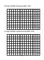
8.6 PAGE 3 (PC860: PORTUGUESE ) (80H – FFH) .......................................................41
8.7 PAGE 4 (PC863: CANADIAN -FRENCH) (80H – FFH)...........................................41
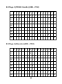
8.8 PAGE 5 (PC865: NORDIC) (80H – FFH) ................................................................42
8.9 PAGE 6 (SLAVONIC) (80H – FFH)...........................................................................42
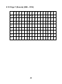
8.10 PAGE 7 (RUSSIA) (80H – FFH) .............................................................................43
9.COMMAND DETAILS ...............................................................................................44
9.1 OVERWRITE MODE .....................................................................................................44
9.2 VERTICAL SCROLL MODE..........................................................................................44
9.3 HORIZONTAL SCROLL MODE ....................................................................................44
9.4 SET THE STRING DISPLAY MODE, AND WRITE STRING TO DISPLAY .....................44
9.5 UPPER LINE MESSAGE SCROLL CONTINUOUSLY.....................................................44
9.6 M OVE CURSOR LEFT ..................................................................................................45
9.7 M OVE CURSOR RIGHT................................................................................................45
9.8 M OVE CURSOR UP ......................................................................................................45
9.9 M OVE CURSOR DOWN...............................................................................................45
9.10 M OVE CURSOR TO HOME P OSITION.......................................................................46
9.11 M OVE CURSOR TO LEFT -MOST POSITION..............................................................46
9.12 M OVE CURSOR TO RIGHT -MOST POSITION ...........................................................46
9.13 M OVE CURSOR TO BOTTOM POSITION...................................................................46
9.14 M OVE CURSOR TO SPECIFIED POSITION ................................................................46
9.15 INITIALIZE DISPLAY .................................................................................................46
9.16 RESET THE WINDOW ................................................................................................46
9.17 CLEAR DISPLAY SCREEN, AND CLEAR STRING MODE..........................................46
9.18 CLEAR CURRENT LINE, AND CANCEL STRING MODE...........................................47
9.19 BRIGHTNESS ADJUSTMENT .....................................................................................47
9.20 SET CURSOR ON OR OFF .......................................................................................47
9.21 SET USER-DEFINED CHARACTERS..........................................................................47
3
9.22 RESET USER DEFINED CHARACTER SET ................................................................47
9.23 CANCEL USER DEFINED CHARACTERS..................................................................47
9.24 STORE THE USER DEFINED CHARACTER INTO EEPROM ...................................47
9.25 RESTORE THE USER DEFINED CHARACTER FROM EEPROM .............................48
9.26 CHARACTER FONT FORMAT ....................................................................................48
10. CONTROL CODE SET ...........................................................................................49
4
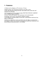
1. Features
(1) Data can be display on 20 columns x 2 lines.
(2) Blue– green color and large character are easy to see
(3)The DIP switches setting emulate commands mode, baud rate and
international character.
(4) Command emulation modes include POS7300/ CD5220 II/ ADM787/
UTC / AEDEX/ Epson/ DSP800.
(5) User’s-defined character and message can be downloaded.
(6) Display area can be controlled by window function.
(7) Provides an interface based in RS-232C, and RS232C baud rate from
4800 to 38400 bps.
(8) Reverse characters can be specified using the Epson command set.
(9) Support software has facility for designing user-defined characters and
downloading setup parameters to the display.
1
2. General Specification
NO
1
2
3
4
5
6
ITEM
Display method
Number of character
Character font
Display color
Brightness
Character type
7
8
9
10
11
12
13
14
15
16
17
Character size
Power supply
Power consumption
Operating Temperature
Operating Humidity
Storage Temperature
Storage Humidity
Data transmission
Synchronization
Handshaking
Signal level
18
19
20
21
Baud rates
Parity
Bit length
Stop bits
DESCRIPTIONS
Vacuum fluorescent display
40 characters (20 columns x 2 lines)
5 x 7 Dot matrix
Blue green
700 cd
96 alphanumeric
13 kinds of international character set
1 kind of user define character
9.0mm x 5.25mm
9 - 35VDC
3-6W
5 - 45
30%-85%
-10 - 55
10%-85%
Serial
Asynchronous
DTR / DSR
MARK = -3 to –15 V (logic “1”)
SPACE = +3 to +15 V (logic “0”)
4800,9600,19200,38400 bps
None, even
8 bits
1 or more
2
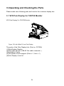
3 Unpacking and Checking the Parts
Please make sure following parts are found in the customer display box.
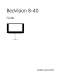
3.1 VFD Pole Display for 720/750 Monitor
VFD Pole Display For 720/750 Monitor
Figure :720 with 300dx PC and Pole Display
The parts of the Pole Display kits: (Part no. P07304)
(1)Pole Display Module
(2)Flat Cable (RJ-45 to DB-9F flat cable connector )
(3)Installation Guide
(4)Two pieces of pole support (22cm x 1, 9cm x 1)
(5)Pole Display cover kit
3
3..4. Pole Display for 800cx Series
VFD Pole Display for 800cx series
The parts of pole display kits: (Part no. P07308)
(1) Pole Display Module
(2) Flat Cable (RJ-45 to DB-9F flat cable connector)
(3) Installation Guide
(4) Two pieces of pole support (22cm x 1, 9cm x 1)
(5) Pole Display cover kit
Flat Type VFD Customer Display for 800cx
The parts of pole display kits: (Part no. P07307)
(1) Pole Display Module
(2) Flat Cable (RJ-45 to DB-9F flat cable connector)
(3) Installation Guide
6
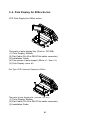
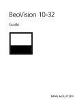
3. 5 Stand Alo ne VFD Pole Display
225 mm
The parts of pole display kits : (Part no.P07303 )
(1) Pole Display Module
(2) Flat Cable (DB-9P to DB -9P flat cable connector)
(3) Base Unit
(4) Two pieces of pole support (1x22cm, 1x9cm)
(5) User’s manual
(6) Power Adapter
7
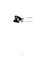
191 mm
93 mm
281 mm
501 mm
Stand Alone VFD Customer Pole Display (Part no. P07303)
P 720 Mo nitor
P 300dx PC
8
Set jumpers on 300dx mainboard
COM1
JP4
COM2
JP3
COM3
JP9
COM4
JP5
1-2 (Default)
3-4
5-6
1-2(Default)
3-4
5-6
1-2(Default)
3-4
5-6
1-2(Default)
3-4
9
Data Line
+5V
+12V
Data Line
+5V
+12V
Data Line
+5V
+12V
Data Line
+5V
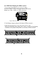
4.4. VFD Pole Display for 800cx series
1.Connect flat cable DB -9P end connector to 800cx
serial port COM4. If COM 4 has been used by other device,
please use COM1, COM2, or COM3 serial port.
COM4
Figure: 800cx rear view
2. Pole Display Jumper setting (on the base of 800cx terminal )
(1).Set JP2 com4 port Pin 1-2 at +12V or Pin 7-8 at +12V.
(2).If com4 has been used, select com1, com2, or com3 for Pole Display.
(3).Below is the jumper setting label on the base of 800cx terminal.
JP1
34
COM1
DCD1
5V +12V RI1
PIN 1
2
COM2
5V +12V DCD2
PIN 9
CASH DRAWER
5V +12V RI2
PIN 1
33
5V +12V +12V +12V +24V +24V
PIN 9
1
Factory Default Setting
JP2
24
2
COM3
DCD3
5V
+12V
PIN 1
23
RI3
COM4
5V
+12V DCD4
PIN 9
5V
+12V
RI4
PIN 1
Factory Default Setting
14
5V
+12V
PIN 9
1
4. 5 Stand Alone VFD Pole Display
4.5.1. Specifications
Data transmission:
Synchronization:
Handshaking:
Serial
Asynchronous
DTR / DSR
MARK = -3 to –15 V (logic “1”)
SPACE = +3 to +15 V (logic “0”)
4800,9600,19200,38400 bps
None, even
8 bits
1 or more
Signal level:
Baud rates:
Parity:
Bit length:
Stop bits:
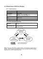
4.5.2. The communication flow
Data flow:
Handshaking flow:
PC/host to display, Display to printer, Printer to
PC/host
Display to PC/host, printer to display,
PC/host to printer
Customer
display
Host
computer
Receipt
printer
: Control connecting direction
: Data connecting direction
Note: There are 200 bytes resident buffer in the display for pass data to
printer. If PC/host keep transmitting the data to printer when the display
inactive DTR or RTS, data will be lost.
15
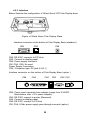
4.5.3. Interface
Below illustrate the configuration of Stand Alone VFD Pole Display base.
Figure of Stand Alone Pole Display Base
Interface connector on the bottom of Pole Display Base (standard )
CN2
CN3
CN6
CN2: RS-232C connects to PC/Host
CN3: Connect to display panel
CN6: Power supply connector
CN1,CN4, CN5: No used
Power Supply Connectors
CN6 / Connector type: DC jack (5.5/2.1)
Interface connector on the bottom of Pole Display Base (option )
CN6
CN5
CN4
CN3
CN2 CN1
CN2: Power input connector from adapter (range from 9-35VDC,
Manufacture offer +12V power adapter)
CN3: RS-232C connect to printer (Reserved)
CN4: Connect to display panel
CN5: RS-232C connect to PC/Host
CN1,CN6: 24Vdc power supply pass-through connects (option)
16
Pin assignment
No
+
-
Signal
Vin
GND
RS232C link to PC/HOST connector
CN2 / Connector type: D-sub 9 pin female
Pin assignment
No
2
3
4
5
6
8
Signal
RXD
TXD
DSR
GND
DSR
DSR
Direction
From PC/Host to display
From printer to PC/Host
From PC/Host to printer
From display to PC/Host
From display to PC/Host
Function description
Receive data
Printer status data
PC/Host ready signal
Signal ground
Display/printer ready signal
Display/printer ready signal
RS232C link to printer connector
CN1 / Connector type: Phone-jack 10P/8C
Pin assignment
No
4,5
6
7
8
9
Signal
GND
DTR
DSR
TXD
RXD
Direction
From PC/Host to printer
From printer to display
From display to printer
From printer to PC/Host
Function description
Signal ground
PC/Host ready signal
Printer ready signal
Printing data
Printer status data
Display penal connector
CN3 / Connector type: Phone-jack 10P/8C
Pin assignment
No Signal Direction
2,3
4,5
6
7
8
9
Vin
GND
DSR
DTR
RXD
TXD
Function description
From Printer to Display
From Display to PC/Host
From PC/Host to Display
From Display to Printer
Power 9 – 33 Vdc
Signal ground
Printer ready signal
Display ready signal
Display/Printing data signal
Printer status data signal
17
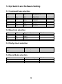
5. Dip Switch and Software Setting
5.1 Command type selection
SW1
ON
OFF
ON
OFF
ON
OFF
ON
OFF
SW2
ON
ON
OFF
OFF
ON
ON
OFF
OFF
SW3
ON
ON
ON
ON
OFF
OFF
OFF
OFF
Command type
POS7300
ESC/POS
ADM 787
DSP800
AEDEX
UTC/P
UTC/S
CD5220
5.2 Baud rate selection
SW8
ON
OFF
ON
OFF
SW9
ON
ON
OFF
OFF
Baud rate (bps)
4800
9600
19200
38400
Default
*
5.3 Parity check selection
SW10
ON
OFF
Parity check
None-parity
Even-parity
Default
*
5.4 Demo Mode selection
SW11
ON
OFF
Show demo string
Enable
Disable
18
Default
*
Default
*
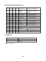
5.4 International character set
SW4
SW5 SW6
SW7 Character set
Code table ( 80H-FFH)
ON
ON
ON
ON
*default
U.S.A.
PC-437(USA, standard
Europe)
OFF
ON
OFF
ON
OFF
ON
OFF
ON
OFF
ON
OFF
ON
OFF
ON
OFF
ON
OFF
OFF
ON
ON
OFF
OFF
ON
ON
OFF
OFF
ON
ON
OFF
OFF
ON
ON
ON
OFF
OFF
OFF
OFF
ON
ON
ON
ON
OFF
OFF
OFF
OFF
ON
ON
ON
ON
ON
ON
ON
OFF
OFF
OFF
OFF
OFF
OFF
OFF
OFF
FRANCE
PC-850(multilingual)
GERMANY
PC-850(multilingual)
U.K.
PC-850(multilingual)
DENMARK I
PC-850(multilingual)
SWEDEN
PC-850(multilingual)
ITALY
PC-850(multilingual)
SPAIN
PC-850(multilingual)
JAPAN
Katakana
NORWAY
PC-850(multilingual)
DENMARK II
PC-850(multilingual)
SLAVONIC
RUSSIA
U.S.A
PC860 (Portuguese)
Not used
Used define pattern from EEPROM
5.5 Self-test
SW11
function
ON
Power on self-test
OFF
No test
* SW12 is reserved
19
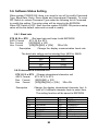
5.6. Software Status Setting
When system POWER ON, there is no need to turn off to modify Command
Type, Baud Rate, Parity, Demo Mode and International Character. To re-set
DIP Switch to various Command Type under the following list of Command
to modify the setting. The setup value will be stored in the EEPROM.
When DIP Switch is OFF. Next time the system POWER ON previous setup
value will be the default value and no need to modify.
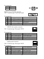
5.6.1. Baud rate
STX 05 B n ETX
/Set baud rate and keep it with EEPROM/
ASCII Format
STX 05 B n ETX
Dec. Format
[02][05][66] n [03]
Hex. Format
[02h][05h][42h] n [03h]
30h n 34h
Description
Change the display communication baud rate.
The baud rate setting can be selected from 4800 to 38400.
N
Baud rate
30h
4800
31h
9600
32h
19200
33h
38400
5.6.2 International character set
STX 05 S n ETX /Change international character set/
ASCII Format
STX 05 S N ETX
Dec. Format
[02][05][83] n [03]
Hex. Format
[02h][05h][53h] n [03h]
30h n 3fh
Description
N
30h
31h
32h
33h
34h
35h
36h
37h
Change the display international character font .A
total of 16 different character fonts to select form.
The setting function will be saved to EEPROM.
International font
U.S.A.
GERMANY
U.K.
DENMARK I
SWEDEN
ITALY
SPAIN
20
n
38h
39h
3Ah
3Bh
3Ch
3Dh
3Eh
3Fh
International font
JAPAN
NORWAY
DENMARK II
SLAVONIC
RUSSIA
U.S.A.
Not used
User define pattern
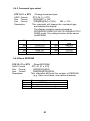
5.6.3 Command type select
STX 05 C n ETX
/Change command type/
ASCII Format
STX 05 C n ETX
Dec. Format
[02][05][67] n [03]
Hex. Format
[02h][05h][43h] n [03h]
30h n 37h
Description
This command will change the command type
and initialize the display.
The display emulation mode is based on
DSP800/ESC/ADM787/POS7301/AEDEX/UTC/C
D5220 mode. The setting function will be saved
to EEPROM.
N
Command type
n
30h
31h
32h
33h
POS7300
ESC/POS
ADM 787
DSP800
34h
35h
36h
37h
Command
type
AEDEX
UTC/P
UTC/S
CD5220
5.6.4 Reset EEPROM
STX 05 07 n ETX
/Reset EEPROM/
ASCII Format
STX 05 07 n ETX
Dec. Format
[02][05][07][n][03]
Hex. Format
[02h][05h][07h][n][03h]
Description
This command will reset the content of EEPROM
(e.g. Demo scroll data, user-define character)
N
31h
32h
33h
Description
Clear all EEPROM contents
Clear upper line data message
Clear lower line data message
21
5.6.5 Save data for demo display
STX 05 L n m ETX /Save demo message to EEPROM/
ASCII Format
STX 05 L n m ETX
Dec. Format
[02][05][76] n m [03]
Hex. Format
[02h][05h][4Ch] n m [03h]
Description
Save demo message for upper line and bottom
line
n = 31h save data message for upper line
n = 32h save data message for lower line
m=data message ; the maximum data character
is under 200
5.6.6 Run Demo message
STX 05 L n m ETX
/Run demo message/
ASCII Format
STX 05 D 08 ETX
Dec. Format
[02][05][68][08][03]
Hex. Format
[02h][05h][44h][08][03h]
Description
Run demo message for the display
22
5.6.7 Set Communication parity
STX 05 P n ETX
/Parity check selection/
ASCII Format
STX 05 P n ETX
Dec. Format
[02][05][80] n [03]
Hex. Format
[02h][05h][50h] n [03h]
n=30h,31h
Description
Change the display communication parity. Set 8
data bit and the parity set for even or non-parity.
N
30h
31h
Parity check
None-parity
Even-parity
5.6.8 Show VFD Firmware Version
STX 05 V 01 ETX
/Show VFD Firmware Version/
ASCII Format
STX 05 V 01 ETX
Dec. Format
[02][05][86][01][03]
Hex. Format
[02h][05h][56h][01h][03h]
Description
Show VFD firmware version
5.6.9 Save title data to EEPROM
STX 05 T 01 ETX
/Save title data to EEPROM/
ASCII Format
STX 05 T 01 ETX
Dec. Format
[02][05][84][01][03]
Hex. Format
[02h][05h][54h][01][03]
Description
Save title data to EEPROM
23
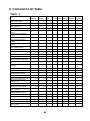
6. Command List Table
Table –1
J2
POS7300
PARTNER EPSON
GIGA
CD5220
D101
UTC/S UTC/P AEDEX ADM788 DSP800
Move cursor right
O
O
O
Move cursor left
O
O
O
Move cursor up
O
O
O
Move cursor down
Move cursor to right -most
position
Move cursor to left-most
position
O
O
O
O
O
O
O
O
O
Move cursor to home position O
Move cursor to bottom
position
Move cursor to specified
O
position
O
O
O
O
O
O
Clear display screen
O
O
O
Clear cursor line
O
O
O
O
O
O
O
O
O
Blink display screen
O
O
O
O
Initialize display
O
O
O
O
O
O
O
O
Brightness adjustment
Select character code table
Select international character
set
Select/cancel reverse
character
O
O
Overwrite mode
O
O
O
O
Vertical scroll mode
O
O
O
O
Horizontal scroll mode
O
O
O
Define download characters
O
O
O
Delete downloads characters
Select/cancel download
character set
O
O
O
O
O
Set/cancel the window range
O
O
Select peripheral device
Set starting/ending position of
maro definition
O
O
O
O
Execute and quit macro
O
Execute self -test
O
Display time
O
Display tim e continuously
O
O
O
O
Display position
Cursor on/off
O
O
O
O
24
O
O
Change to UTC enhanced
mode
Change to UTC standard
mode
O
O
Write string to upper line
O
O
O
O
Write string to lower line
Upper line message scroll
continuously
Bottom line message scroll
continuously
Message vertical down scroll
continuously
Message vertical upper scroll
continuously
O
O
O
O
O
O
O
O
Carriage return
O
O
Line feed
O
O
Back space
O
O
Horizontal tab
O
Command type select
O
O
O
O
O
O
O
25
O
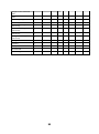
Table-2
J2
PARTNER EPSON
GIGA
POS7300 CD5220 D101 UTC/S UTC/P AEDEX ADM788 DSP800
Upper line message scroll once
pass
O
O
Change attention code
O
O
Two line display
Clear upper line and move cursor
to upper left-end position
Clear bottom line and move cursor
to bottom left-end position
Set period to upper line, last n
position
O
O
O
O
O
Set line blinking, upper line
O
O
Clear line blinking, upper line
Clear field 1 and move cursor to
field 1, first position
Clear field 2 and move cursor to
field 2,first position
Clear display range from n position
to m position and move cursor to n
position
Save the current displaying data to
n layer for demo display
O
O
Save demo message to EEPROM
Store the use define character into
EEPROM
Store the use define character
from EEPROM
O
O
O
O
O
O
O
O
O
Turn annunciator on/off
O
Specify period
O
Specify comma
Specify semicolon (period +
comma)
O
O
26
7. Command
7.1. POS7300 series command set
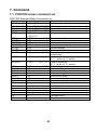
POS7300 Standard Mode Command List
Command
ESC F A .. CR
ESC F B .. CR
ESC F D .. CR
ESC F O .. CR
ESC P x y
ESC _ n
ESC DC1
ESC DC2
ESC DC3
ESC @
US MD2 n
US MD1 n
Code (hex)
1B 46 41 [DATA X 40] 0D
1B 46 42 [DATA X 40] 0D
1B 46 44 [DATA X 40] 0D
1B 46 4F [DATA X 40] 0D
1B 50 x y
1 x 20,y=1,2
1B 5F n
n=00,01
1B 11
1B 12
1B 13
1B 40
1F 02 n
n=01~0Ch
1F 01 n
n=01~0Ch
US DC1 n
1F 11 n
US DC2 n
1F 12 n
US E n
NULL H
NULL K
NULL M
NULL P
NULL G
NULL O
BS
HT
LF
HOM
CLR
CR
CAN
1F 45 n
0 48
0 4B
0 4D
0 50
0 47
0 4F
08
09
0A
0B
0C
0D
18
Function Description
Write string to upper line
Write string to lower line
Upper line message scroll continuously
Bottom line message s croll continuously
Move cursor to specified position
Set cursor on/off
Overwrite mode
Vertical scroll mode
Horizontal scroll mode
Initialize display
Message vertical down scroll continuously
Message vertical upper scroll
continuously
n=’1’,’2’ Set line blinking
N=’1’ up line, n=’2’ low line
n=’1’,’2’ Clear line blinking
N=’1’ up line, n=’2’ low line
n=0~FFh Blink display screen
Move cursor up
Move cursor left
Move cursor right
Move cursor down
Move cursor to left-most position
Move cursor to right-most position
Back space
Horizontal tab
Line feed
Move cursor to home position
Clear display screen
Carriage return
Clear cursor line , and clear string mode
27
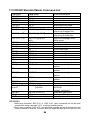
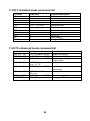
7.2 CD5220 Standard Mode Command List
Command
ESC DC1
US SOH
ESC DC2
US STX
ESC DC3
US ETX
ESC Q A .. CR
Code (hex)
1B 11
1F 01
1B 12
1F 02
1B 13
1F 03
1B 51 41 [n]x20 0D
ESC Q B .. CR
1B 51 42 [n]x20 0D
ESC Q D .. CR
ESD [ D
BS
ESC [ C
HT
ESC [ A
US LF
ESC [ B
LF
ESC [ H
HOM
ESC [ L
1B 51 44 [n]xm 0D
m 40
1B 5B 44
08
1B 5B 43
09
1B 5B 41
1F 0A
1B 5B 42
0A
1B 5B 48
0B
1B 5B 4C
CR
0D
ESC [ R
1B 5B 52
US CR
1F 0D
ESC [ K
US B
ESC b [n]xC8
[m]xC8
1B 5B 4B
1F 42
1B 62 [n]xC8h
[m]xC8h
ESC # n
US @
US E n
1B 23 n (n=30~37)
1F 40
1F 45 n
Function description
Overwrite mode
Overwrite mode
Vertical scroll mode
Vertical scroll mode
Horizontal scroll mode
Horizontal scroll mode
Set the string display mode,
write string to upper line.
Set the string display mode,
write string to lower line.
Upper line message scroll
continuously
Move cursor left
Move cursor left
Move cursor right
Move cursor right
Move cursor up
Move cursor up
Move cursor down
Move cursor down
Move cursor to home position
Move cursor to home position
Move cursor to left-most
position
Move cursor to left-most
position
Move cursor to right-most
position
Move cursor to right-most
position
Move cursor to bottom position
Move cursor to bottom position
Save demo message to
EEPROM
n=Line 1; m=Line 2
Command type select
Execute self test
Blink display mode
(REMARK)
*While using command “ESC Q A” or “ESC Q B”, other commands can not be used
except when using command “CLR” to change operating mode.
*When using command “ESC Q D”, the upper line message will scroll continuously until
a new command is received, it will then clear the upper line and move the cursor to the
28
upper left-end position.
29
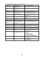
CD5220 Standard Mode Command List-2
Command
ESC I x y
CLR
Code (hex)
1B 6C x y / 1F 24 x y
1x20, y=1,2
1F 24 x y
1x20,y=1,2
1B 40
1B 57 1 x1 x2 y
1x1x2 20 y=1,2
0C
CAN
18
ESC * n
US X n
ESC & s n m
[a (P1…Pa)]x
(m -n+1)
ESC ? n
ESC % n
1B 2A n
1n 4
1F 58 n
1n 4
1B 26 1 n m
[a(p1…pa)]x (m-n+1)
20 n m FF
1B 3F n
n=20h~7Fh Deletes download characters.
1B 25 n
n=00,01
Select/cancel download character
set.
1B 5F n
n=00,01 Set cursor on/off
1B 66 n
Select international fonts, refer *2
1B 63 n
Select fonts, ASCII code or JIS
code, refer *3
1B 3D n
Select peripheral device, display
n=01,02,03,31,32,33
or printer
n=01,enable printer
n=02,enable display
n=03,enable printer, display
1B 73 01
Store the use define character
into EEPROM
1B 64 01
Store the use define character
from EEPROM
US $ x y
ESC @
ESC W s x1 x2 y
ESC _ n
ESC f n
ESC c n
ESC = n
ESC s 1
ESC d 1
30
Function description
Move cursor to specified position
Move cursor to specified position
Initialize display
Set or cancel the window range
at horizontal scroll mode
Clear display screen, and clear
string mode
Clear cursor line, and clear string
mode
Brightness adjustment
Brightness adjustment
Define download characters.
A=1-5 p1..p5=row1..row5
*2: The parameter of international fonts set control by command
“ESC f n”
Parameter
‘A’
‘G’
’I’
‘J’
‘U’
‘F’
‘S’
‘N’
‘W’
‘D’
‘E’
‘L’
‘R’
n
International Font Set
U.S.A.
Germany
Italy
Japan
U.K.
France
Spain
Norway
Sweden
Denmark I
Denmark II
Slavonic
Russia
*3: The parameter of the code table control by command “ESC c n”
Parameter “n”
International Font Set
‘A’
‘J’
‘L’
‘R’
Compliance with ASCII code
Compliance with JIS code
Compliance with SLOVONIC code
Compliance with RUSSIA code
31
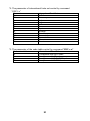
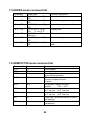
7.3 UTC standard mode command list
Command
BS
HT
LF
CR
DLE
DC1
Code (hex)
08
09
0A
0D
10 n
0 n 28h
11
Function description
Back space
Horizontal tab
Line feed
Carriage return
Display position
Over write display mode
DC2
DC3
DC4
US
ESC d
12
13
14
1F
1B 64
Vertical scroll mode
Cursor on
Cursor off
Clear display
Change to UTC enhanced mode
7.4 UTC enhanced mode command list
Command
ESC u A .. CR
ESC u B .. CR
ESC u D .. CR
Code (hex)
1B 75 41 [data x 40] 0D
1B 75 42 [data x 40] 0D
1B 75 44 [data x 40] 0D
ESC u E .. CR
1B 75 45 h h ':' m m 0D
h, m = '0' - '9'
1B 75 46 [data x 40] 0D
ESC u F .. CR
ESC u H .. CR
ESC u I .. CR
ESC RS CR
1B 75 48 n m 0D
20h n, m
1B 75 49 [data x 40] 0D
1B 0F 0D
32
Function description
Upper line display
Bottom line display
Upper line message scroll
continuously
Display time
Upper line message scroll
Once pass
Change attention code
Two line display
Change to UTC standard mode
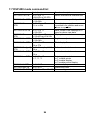
7.5 AEDEX mode command list
Command
! # 1 … CR
! # 2 … CR
! # 4 … CR
! # 5 … CR
! # 8 … CR
! # 9 … CR
! # 6 … CR
Code (hex)
21 23 31 [data x 40]
0D
21 23 32 [data x 40]
0D
21 23 34 [data x 40]
0D
21 23 35 h h ':' m m
0D
h, m='0'-'9'
21 23 38 n m 0D
20H,n, m
21 23 39 [data x 40]
0D
21 23 36 [data x 40]
0D
Function description
Upper line display
Bottom line display
Upper line message scroll
Display time
Change attention code
Two line display
Upper line message scroll once
pass
7.6 ADM787/788 mode command list
Command
CLR
CR
SLE1
Code (hex)
0C
0D
0E
SLE2
0F
DC0
10 n
DC1
11 n
DC2
12n
SF1
1E
SF2
1F
Function description
Clear display
Carriage return
Clear upper line and move cursor to
upper left-end position
Clear bottom line and move,
Cursor to bottom left-end
Position
Set period to upper line last n
position
31H n 37H
Set line blinking, upper line
n='1' up line, n='2' low line
Clear line blinking, upper line
n='1' up line, n='2' low line
Clear field 1 and move cursor to field 1,
first position
Clear field 2 and move cursor to field 2,
first position
33
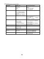
7.7 DSP-800 mode command list
Command
EOT SOH I n ETB
EOT SOH P n ETB
EOT SOH C n m
ETB
Code (hex)
04 01 49 n 17
n=00~0Fh or 30~3Fh
04 01 50 n 17
n=31h-58h
04 01 43 n m 17
31h n m 58h
EOT SOH S n ETB
04 01 53 n 17
n=31h-35h
EOT SOH D n m
04 01 44 n m 17
ETB
n=31h-4Fh,m=31h-33h
EOT SOH A n ETB 04 01 41 n 17
n=31h-34h
EOT SOH F n ETB 04 01 46 n 17
00h n FFh
EOT SOH & n [ px5] 04 01 26 n p1…p5 17,
ETB
20h n
EOT SOH ? n ETB 04 01 3F n 17
20h n
EOT SOH = n ETB 04 01 3D n 17
n='1', '2', '3'
EOT SOH % ETB
EOT SOH @ ETB
EOT SOH # n ETB
Function descriptions
Select international character set
Move cursor to specified position
Clear display range from
n position to m position and move
cursor to n position
Save current view message to n
layer for demo view data
Display the saved demo message
Brightness adjustment
Blink display Screen
Define download characters
Delete download characters
Select peripheral device.
n='1',enable printer
n='2',enable display
n='3',enable printer display
04 01 25 17
Initialize display
04 01 40 17
Execute self-test
04 01 23 n 17, n=30~37h Command type select
34
7.8 EPSON ESC/POS command list
EPSON ESC/POS command list-1
Command
Code (hex)
HT
09
BS
08
US LF
1F 0A
LF
0A
US CR
1F 0D
CR
0D
HOM
0B
US B
1F 42
US $ x y
1F 24 x y
(x=1~20, y=01,02)
CLR
0C
US X n
1F 58 n
(01 n 04)
US E n
1F 45 n
(n=00~ffh)
ESC @
1B 40
ESC t n
1B 74 n
(n=00-0fh)
ESC R n
1B 52 n
(n=00-0fh)
US r n
1F 72 n
(n=00,01)
US MD1
1F 01
US MD2
1F 02
US MD3
1F 03
ESC & s n m 1B 26 1 n m
[a(p1..pa)]x
[a(p1..pa)]x m-n
m-n
20<n<=m<=ff
ESC ? n
1B 3F n (20 n FF)
ESC % n
1B 25 n (n=0,30,1,31)
CAN
ESC # n
US # n m
US C n
US . n
US , n
US ; n
18
1B 23 n
(30h n 38h)
1F 23 n m, (n=0 or 1,0<m 20)
1F 43 n
(n=1,31 then on)
1F 2E n, n=a displayable
character code
1F 2C n, n=a displayable
character code
1F 3B n, n=a displayable
character code
35
Function description
Move cursor right.
Move cursor left.
Move cursor up.
Move cursor down.
Move cursor to right–most position.
Move cursor to left-most position.
Move cursor to home position.
Move cursor to bottom position.
Move cursor to specified position.
Clear display screen.
Brightness adjustment.
Blink display screen.
Initialize display.
Select character code table.
Select international character set.
Select/cancel reverse character.
Specify overwrite mode.
Specify vertical scroll mode.
Specify horizontal scroll mode.
Define download characters.
20<n<=m<=ff
a=1-5
p1 .. p5 = row1 .. row5
Delete downloads characters.
Select/cancel download character
set.
Clear cursor line
Command type select
Turn annunciator on/off
Set cursor on/off
Specify period
Specify comma
Specify semicolon (period +comma)
EPSON Esc/pos command list
Command
Code (hex)
ESC W n s x1 y1 x2 y2 1 B 57 n s x1 y1 x2 y2
n=1,2,3,4
s=0,1
ESC = n
US :
1B 3D n
n=1,31,select printer
n=2,32,select display
n=3,33,
select printer, display
1F 3A
US ^ n m
1F 5E n m
00 (n, m) ff
n=Word time
m=show string time
US @
US T h m
US U
ESC s 1
1F 40
1F 54 h m
0<=h<=17h,
0<=m<=3bh
1F 55
1B 73 01
ESC d 1
1B 64 01
Function description
Specify/cancel the window
range.
1<=x1<=x2<=20
1<=y1<=y2<=2
Select peripheral device.
Set starting/ending position of
macro definition.
Ex.: 1F 3A … … … … . (macro
string ) ..…. 1F 3A
Execute and quit macro.
It’s an interval of n between
the two words.
It’s an interval of m between
the two string.
Execute self - test
Display time
Display time continuously
Store define download
character to EEPROM
Restore user define character
from EEPROM
36
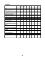
Set international font for ESC/POS (Table 7-11)
n
0
1
2
3
4
5
6
International font set
U.S.A
FRANCE
GERMANY
U.K.
DENMARK I
SWEDEN
ITALY
n
7
8
9
10
11
12
15
International font set
SPAIN
JAPAN
NORWAY
DENMARK II
SLAVONIC
RUSSIA
Reserved
Select code for ESC/POS (Table 7-12)
n
0
1
2
3
4
5
6
7
International font set (80H~FFH)
Page 0, (PC437: U.S.A., standard Europe)
Page 1, (Katakana for Japan)
Page 2, (PC850: multilingual)
Page 3, (PC860: Portuguese)
Page 4, (PC863: Canadian-French)
Page 5, (PC865: Nordic)
Page 6, (SLAVONIC)
Page 7, (RUSSLA)
37
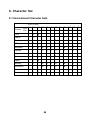
8. Character Set
8.1 International Character Sets
ASCII Code
Country
Hex 23
Dec 35
24
40
5B
5C 5D
5E
60
7B
7C
7D 7E
36
64
91
92
93
94
96
123 124 125 126
U.S.A
#
$
@
[
\
]
^
`
{
|
}
~
France
#
$
à
°
ç
§
`
é
ù
è
¨
Germany
#
$
§
Ä
Ö
Ü
`
ä
ö
ü
â
U.K
£
$
@
[
\
]
`
{
|
}
~
Denmark I
#
$
@
Æ
Ø
Å
`
æ
ø
å
~
Sweden
#
¤
É
Ä
Ö
Å
é
ä
ö
å
ü
Italy
#
$
@
°
\
é
ù
à
ò
è
ì
Spain
Pt
$
@
¡
Ñ
¿
`
¨
ñ
}
~
Japan
#
$
@
[
¥
]
`
{
|
}
~
Norway
#
¤
É
Æ
Ø
Å
é
æ
ø
å
ü
Denmark II
#
$
É
Æ
Ø
Å
é
æ
ø
å
ü
Slawie
#
$
@
[
\
]
`
{
|
}
~
Russia
#
$
@
[
\
]
^
^
^
^
Ü
^
^
^
Ü
Ü
^
^
`
{
|
}
~
38
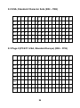
8.2 USA, Standard Character Sets (20H – 7EH)
00 01 02 03 04 05 06 07 08 09 0A 0B 0C 0D 0E 0F
20H
SP !
“
#
$
%
&
‘
(
)
ς
+
,
-
.
/
30H
0
1
2
3
4
5
6
7
8
9
:
;
<
=
>
?
40H
@ A
B
C
D
E
F
G
H
I
J
K
L
M
N
O
50H
P
Q
R
S
T
U
V
W
X
Y
Z
[
\
]
^
_
60H
`
a
b
c
d
e
f
g
h
i
j
k
l
m
n
o
70H
p
q
r
s
t
u
v
w
x
y
Z
{
|
}
~
SP
8.3 Page 0 (PC437: USA, Standard Europe) (80H – FFH)
00 01 02 03 04 05 06 07 08 09 0A 0B 0C 0D 0E 0F
80H
Ç
ü
é
â
ä
à
å
ç
ê
ë
è
ï
î
ì
Ä
Å
90H
É
æ
Æ
ô
ö
ò
û
ù
ÿ
ö
Ü
¢
£
¥
Pt
ƒ
A0H
á
í
ó
ú
ñ
Ñ
a
o
¿
¬
½
¼
¡
«
»
á
ß
Ã
ð
Ó
ó
ì
ô
Ô
Ù
ä
B0H
C0H
D0H
E0H
F0H
±
÷
39
°
è
·
ø
n
²
SP
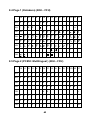
8.4 Page 1 (Katakana) (80H – FFH)
00 01 02 03 04 05 06 07 08 09 0A 0B 0C 0D 0E 0F
80H
á
â
ã
90H
f
§
IE
A0H
SP
ç
è
IR
ë
ì
ð
ñ
ó
ô
-1
²
³
x
½
1
Ô
/
±
B0H
C0H
D0H
"
E0H
«
F0H
»
~
8.5 Page 2 (PC850: Multilingual ) (80H – FFH)
00 01 02 03 04 05 06 07 08 09 0A 0B 0C 0D 0E 0F
80H
Ç
ü
é
â
ä
à
å
ç
ê
ë
è
ï
î
ì
Ä
Å
90H
É
æ
Æ
ô
ö
ò
û
ù
ÿ
ö
Ü
ø
£
Ø
×
ƒ
A0H
á
í
ó
ú
ñ
Ñ
a
o
¿
®
¬
½
¼
¡
«
»
Á
Â
À
©
¢
¥
ã
Ã
B0H
C0H
¤
D0H ð
Ð
Ê
Ë
È
ý
Í
Î
Ï
E0H
ó
ß
ô
ò
õ
Õ
ì
þ
Þ
F0H
¯
±
¾
¶
§
÷
¸
40
¦
Ì
¯
Ú
Û
Ù
ý
Ý
¨
ÿ
¹
³
²
´
SP
8.6 Page 3 (PC860: Portuguese) (80H – FFH)
00 01 02 03 04 05 06 07 08 09 0A 0B 0C 0D 0E 0F
80H
Ç
ü
é
â
ã
à
Á
ç
ê
Ê
è
Í
Ô
ì
Ã
Â
90H
É
À
È
ô
õ
ò
Ú
ù
Ì
Õ
Ü
¢
£
Ù
Pt
Ó
A0H
á
í
ó
ú
ñ
Ñ
a
o
¿
Ò
¬
½
¼
¡
«
»
á
â
Ã
ð
Ó
ó
ì
ô
Ô
è
Ù
ä
B0H
C0H
D0H
E0H
F0H
±
÷
ø
n
°
²
SP
8.7 Page 4 (PC863: Canadian-French) (80H – FFH)
00 01 02 03 04 05 06 07 08 09 0A 0B 0C 0D 0E 0F
80H
Ç
ü
é
â
Â
à
¶
ç
ê
ë
è
ï
î
90H
É
È
Ê
ô
Ë
Ï
û
ù
¤
Ô
Ü
¢
£
A0H
¦
´
ó
ú
¨
¸
³
¯
Î
¬
½
¼
á
â
Ã
ð
Ó
ó
ì
ô
Ô
Ù
ä
À
§
Ù
Û
ƒ
¾
«
»
B0H
C0H
D0H
E0H
F0H
±
÷
41
°
è
·
ø
n
²
SP
8.8 Page 5 (PC865: Nordic) (80H – FFH)
00 01 02 03 04 05 06 07 08 09 0A 0B 0C 0D 0E 0F
80H
Ç
ü
é
â
ä
à
å
ç
ê
ë
è
ï
î
ì
Ä
Å
90H
É
æ
Æ
ô
ö
ò
û
ù
ÿ
Ö
Ü
ø
£
Ø
Pt
ƒ
A0H
á
í
ó
ú
ñ
Ñ
a
o
¿
¬
½
¼
¡
«
¤
á
â
Ã
ð
Ó
ó
ì
ô
Ô
Ù
ä
B0H
C0H
D0H
E0H
F0H
±
÷
è
°
ø
n
·
²
SP
8.9 Page 6 (Slavonic) (80H – FFH)
00 01 02 03 04 05 06 07 08 09 0A 0B 0C 0D 0E 0F
æ
80H
Ç
ü
é
â
ä
ù
90H
é
Å
í
ô
ö
¼
A0H
á
í
ó
ú
¹
¹
ž
á
â
B0H
C0H
D0H
E0H
ó
F0H
–
â
ç
Á
ë
õ
œ
œ
Ö
Ü
ž
ê
ê
Ÿ
î
è
º
ã
ã
Ÿ
ä
æ
á
õ
è
º
«
»
¿
¿
¤
ã
ë
ã
ò
í
î
ì
ô
ñ
ñ
ò
š
š
à
Í
¡
¢
§
÷
Ï
42
õ
þ
ù
þ
ú
à
ý
ý
¨
ÿ
ø
ø
SP
8.10 Page 7 (Russia) (80H – FFH)
00 01 02 03 04 05 06 07 08 09 0A 0B 0C 0D 0E 0F
80H
À
Á
Â
Ã
Ä
Å
Æ
Ç
É
É
Ê
Ë
Ì
Í
Î
Ï
90H
Ð
Ñ
Ò
Ó
Ô
Õ
Ö
×
Ø
Ù
Ú
Û
Ü
Ýá
Þ
ß
A0H
à
á
â
ã
ä
å
æ
ç
è
é
ê
ë
ì
í
î
ï
ð
ñ
ò
ó
ô
õ
ö
÷
ø
ù
ú
û
ü
ý
þ
ÿ
¥
K
H
è
Y
Y
h
´
k
h
è
Y
Y
SP
B0H
C0H
D0H
E0H
F0H
43
9.Command details
9.1 Overwrite mode
In this mode, the cursor will move rightward and begin from the upper
left-end position. When the cursor reached the end of the upper line, the
cursor will move down to the bottom left-end position to continue. When the
cursor reached the end of the bottom line, it will move up the upper left-end
position and overwrite the previous characters.
9.2 Vertical scroll mode
In this mode, the cursor will move rightward. The cursor will begin from the
upper left-end position until it reached the end of the upper line, the cursor
will then move down to the bottom left -end position to continue until it
reached the end of the bottom line.
9.3 Horizontal scroll mode
In this mode, the extend of the cursor activity is bond by predefined range,
limited to the upper line.(Please refer to Set or cancel window command),
where the default window is the whole upper line. The cursor will begin
from the left-end of the range and move rightward until it reached the end
of the range, to continue, the characters that comes thereafter will start
pushing the previous characters leftward from the right-end, scrolling the
characters to the left.
9.4 Set the string display mode, and write string to display
Set the string display mode, write to upper or lower line d1 d2 d3 ….. dn
{1 n 20} ‘A’ stands for the upper line, ‘B’ stands for the lower line, The
string display mode will be cancelled and back to last mode after receive
CLR or CAN
9.5 Upper line message scroll continuously
The message (previously defined) will scroll continuously in the horizontal
direction until a new command is received.
44
9.6 Move cursor left
When the current cursor is at the left-end position, this command operates
differently depends on the display mode. Overwrite mode: When the
cursor reached the left-end of the lower line, it will continue to the right-end
of the upper line, overwrite previous characters.
When it reached the left end of the upper line, it will continue to the
right-end of the lower line. Vertical scroll mode: When the cursor reached
the left-end of the lower line, the lower line will scroll up and replace the
previous upper line, the lower line will be cleared and the cursor will
continue to the right end of the lower line. Horizontal scroll mode: The
cursor will remain stationary.
9.7 Move cursor right
Move the cursor to the right. When the cursor reached the right-end, this
command operates differently depending on the display mode. Overwrite
mode: When the cursor reached the right-end of the lower line, it will
continue to the left-end of the upper line, overwrite previous characters.
When it reached the right-end of the upper line, it will continue to the
right-end of the lower line. Vertical scroll mode: When the cursor reached
the right -end of the lower line, the lower line will scroll up to replace the
upper line, the lower line is cleared and ready to continue characters there
after. Horizontal scroll mode: The cursor will remain stationary.
9.8 Move cursor up
Move the cursor up one line. When the cursor is on the upper line, this
command operates differently depending on the display mode.
Overwrite mode: The cursor is moved to the same column the lower line.
Vertical scroll mode: The characters display on the upper line is scrolled to
the lower line, and the upper line is cleared. The cursor will remain at the
same position.
Horizontal scroll mode: The cursor will remain stationary.
9.9 Move cursor down
Move the cursor down one line. When the cursor reached the lower line,
this command operates differently depending on the display mode.
Overwrite mode: The cursor is moved to the same column on the upper
line.
Vertical scroll mode: The characters display on the lower line are scrolled
to the upper line, and the lower line is cleared. The cursor will remain at
45
the same position.
Horizontal scroll mode: The cursor will remain stationary.
9.10 Move cursor to home position
The cursor will move to the left-end position of the upper line
9.11 Move cursor to left-most position
The cursor will be moved to the left-end position of the current line.
9.12 Move cursor to right-most position
The cursor will be moved to the right-end position of the current line.
9.13 Move cursor to bottom position
The cursor will be moved to the right-end position on the lower line.
9.14 Move cursor to specified position
The cursor will be moved to the x column on the y line.
9.15 Initialize display
The data in the input buffer will be cleared and reset from default.
9.16 Reset the window
Reset the window on the display. When s=0, window is cancelled (values:
x1, x2, and y are not required.)
When s=1 the window will be reset (values: x1, x2, and y are required.) The
x1 and x2 set the position of the left column and right column, respectively,
of the window. The y sets the upper line or the lower line of the window.
This function is valid within the horizontal mode.
9.17 Clear display screen, and clear string mode
All the display characters will be cleared, and the string mode will be
cancelled.
46
9.18 Clear current line, and cancel string mode
The current line is cleared, and the string mode is cancelled.
9.19 Brightness adjustment
Adjust the brightness of the vacuum fluorescent display.
When n=3,brightness=70%
When n=4,brightness=100%
9.20 Set cursor ON or OFF
When n=0, cursor is OFF
When n=1, cursor is ON
9.21 Set user-defined characters
The n defines the beginning character code, and m defines the ending
character code. When only one character is defined, use n=m. The ‘a’
denotes the number of dots in the horizontal direction. When a<5, the dot
pattern for ‘ a’ on the right side of the user-defined characters are padded
with spaces p1 .. pa, the dot data is to defined the characters. This
indicates the dot pattern for /a/ in the horizontal direction from the left side.
9.22 Reset user defined character set
When n=1, user-defined characters are selected. When the user-defined
characters are not defined by the ESC & command, the internal character
set will be displayed.
When n=0, user-defined characters are cancelled and the international
character set is selected.
9.23 Cancel user defined characters
User-defined characters are cancelled.
This command cancels the defined characters specified by n. If specified
code is transmitted after the pattern is cancelled, the international character
will be displayed.
9.24 Store the user defined character into EEPROM
If EEPROM is not supported, this command is ignored.
47
9.25 Restore the user defined character from EEPROM
If EEPROM is not supported, this command is ignored.
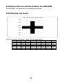
9.26 Character font format
One font consists of 5 bytes’ string. The string format is:
Bit
Byte 1
Byte 2
Byte 3
Byte 4
Byte 5
7
0
0
0
0
0
6
R7C1
R7C2
R7C3
R7C4
R7C5
5
R6C1
R6C2
R6C3
R6C4
R6C5
4
R5C1
R5C2
R5C3
R5C4
R5C5
48
3
R4C1
R4C2
R4C3
R4C4
R4C5
2
R3C1
R3C2
R3C3
R3C4
R3C5
1
R2C1
R2C2
R2C3
R2C4
R2C5
0
R1C1
R1C2
R1C3
R1C4
R1C5
10. Control code set
HEX
00H
01H
02H
03H
04H
05H
06H
07H
08H
09H
0AH
0BH
0CH
0DH
0EH
0FH
CODE
NULL
SOH, MD1
STX, MD2
ETX, MD3
EOT, MD4
ENQ, MD5
ACK, MD6
BEL, MD7
BS, MD8
HT
LF
VT, HOM
FF, CLR
CR
SO, SLE1
SI, SLE2
HEX
10H
11H
12H
13H
14H
15H
16H
17H
18H
19H
1AH
1BH
1CH
1DH
1EH
1FH
CODE
DLE
DC1
DC2
DC3
DC4
NAK
SYN
ETB
CAN
EM
SUB
ESC
FS
GS
RS, SF1
US, SF2
49