1
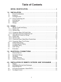
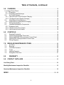
Data Cool
Installation, Operation and Maintenance Manual
2 and 3 ton
Air, Water and Glycol Cooled DX and Chilled Water
CONGRATULATIONS ON THE SELECTION OF A DATA AIRE PRECISION ENVIRONMENTAL
CONTROL SYSTEM. PROPER INSTALLATION, OPERATION AND MAINTENANCE OF THIS
EQUIPMENT WILL ENSURE YEARS OF OPTIMAL PERFORMANCE.
This manual is intended to assist trained service personnel by providing
necessary guidelines for this particular equipment. Installation and service to
Data Aire units should be done by qualified individuals with an adequate
background in areas such as HVAC, electrical, plumbing and electronics, as
applicable.
Service performed by unauthorized or unqualified technicians may void
manufacturers’ warranties and could result in property damage and/or
personal injury.
Special care should be given to those areas where these symbols appear.
2
Table of Contents
MODEL IDENTIFICATION ........................................................................ 5
1.0
INSTALLATION .......................................................................................... 6
1.1
1.2
1.3
1.3.1
1.4
1.5
1.6
2.0
PIPING ........................................................................................................ 8
2.1
2.1.1
2.1.2
2.1.3
2.1.4
2.2
2.2.1
2.2.2
2.2.3
2.2.4
2.3
2.4
2.5
2.6
2.7
3.0
3.1
3.2
3.3
3.4
3.5
4.0
4.1
4.2
4.3
4.4
4.4.1
Room Considerations ................................................................................................ 6
Inspection .................................................................................................................. 6
Locating the Unit ........................................................................................................ 6
Indoor Condensing Unit .............................................................................................. 7
Leveling Legs ............................................................................................................ 7
Paperwork ................................................................................................................. 7
Storage ...................................................................................................................... 7
Split Air Cooled Unit Piping ........................................................................................ 8
Liquid Lines ............................................................................................................... 8
Suction Lines ............................................................................................................. 8
Connection Sizes, Air Cooled Units ............................................................................ 9
Field Piping, Remote Condensing Unit....................................................................... 9
Water/Glycol Cooled Unit Piping .............................................................................. 10
Liquid Lines ............................................................................................................. 10
Suction Lines ........................................................................................................... 10
Connection Sizes, Water/Glycol Cooled Units .......................................................... 11
Connection Sizes, Fluid Coolers .............................................................................. 11
Chilled Water Piping ................................................................................................ 11
Condensate Drain Piping ......................................................................................... 11
Humidifier Piping ..................................................................................................... 12
Leak Testing ............................................................................................................ 12
Evacuation ............................................................................................................... 12
ELECTRICAL CONNECTIONS ............................................................... 13
Electrical Service ..................................................................................................... 13
Nameplate Ratings .................................................................................................. 13
Grounding ................................................................................................................ 13
Voltage Tolerance .................................................................................................... 13
Auxiliary Control Wiring ............................................................................................ 13
INSTALLATION OF REMOTE OUTDOOR HEAT EXCHANGER .......... 14
Rigging .................................................................................................................... 14
Locating the Remote Heat Exchanger ...................................................................... 14
Electrical Service ..................................................................................................... 14
Air Cooled Condensers - Model DRCU .................................................................... 15
Fan Speed Control ................................................................................................... 15
3
Table of Contents, continued
5.0
CHARGING ..................................................................................................................... 15
5.1 Voltage Phase Check ............................................................................................................ 15
5.1.1 Evaporator ..................................................................................................................... 15
5.1.2 Secondary Heat Exchanger ............................................................................................ 15
5.2
Air Cooled Systems ....................................................................................................... 15
5.2.1 Split Indoor Air Cooled Systems Charging ...................................................................... 15
5.2.2 Fan Speed Control System Charging ............................................................................. 16
5.3
Water/Glycol Cooled Systems ........................................................................................ 17
5.3.1 Water/Glycol Cooled Systems Charging ......................................................................... 17
5.4
Refrigerant Handling ...................................................................................................... 18
5.5
Important Refrigeration Components .............................................................................. 18
5.5.1 Expansion Valve ............................................................................................................ 18
5.5.2 High Pressure Cutout Switch ......................................................................................... 18
5.5.3 Low Pressure Cutout Switch .......................................................................................... 18
6.0
6.1
6.2
6.3
6.4
6.5
7.0
7.1
7.2
7.3
7.4
7.5
7.6
CONTROLS ................................................................................................................... 18
Standard Thermostat ...................................................................................................... 18
Optional Programmable Thermostat............................................................................... 19
Optional Mini DAP II Microprocessor Control Panel ........................................................ 19
Optional DAP II Microprocessor Control Panel ............................................................... 19
Wiring Diagrams ............................................................................................................ 19
REGULAR MAINTENANCE ITEMS .............................................................. 20
Air Filters ....................................................................................................................... 20
Bearings ........................................................................................................................ 20
Humidifier Canisters ...................................................................................................... 20
Fuses ............................................................................................................................ 20
Heating Elements........................................................................................................... 20
Refrigerant Filter Drier ................................................................................................... 21
8.0
WARRANTY ............................................................................................... 22
9.0
CONTACT DATA AIRE ................................................................................................ 23
Line Sizing Chart ......................................................................................................................... 24
Monthly Maintenance Inspection Checklist .............................................................................. 25
Quarterly Maintenance Inspection Checklist ............................................................................ 26
INDEX .................................................................................................................................. 28 - 29
4
Model Identification
5
1.0 INSTALLATION
There is no intent on the part of Data Aire, Inc. to define local codes or statutes which may
supercede common trade practices. The manufacturer assumes no responsibility for their
interpretation. Consult local building codes and the National Electrical Code for special
installation requirements.
1.1
Room Considerations
Precision air conditioning equipment is designed to control spaces within close tolerances of temperature
and humidity. However, the room must be built with a proper vapor barrier. A film of polyethylene is often
used on walls and ceilings. Walls and floors must also be painted with a vapor-seal paint. All doors to
the data room should be equipped with weather seals to prevent the infiltration of non-neutral conditioned
air from entering the data room. Failure to provide a vapor barrier can compromise the ability to control
space conditions.
Introduction of outside air into the space should be minimized. Outside air in excess of 5% of the total
circulated air volume can have a significant effect on the overall space conditions and result in poor
space control. All outside air that is introduced into the space should be conditioned to the humidity and
temperature parameters of the computer room air conditioning (CRAC) unit set points to maintain proper
room conditions and to prevent the CRAC units from running excessively to maintain the room conditions.
1.2
Inspection
This Data Aire unit has been factory run-tested and has gone through a comprehensive inspection prior
to its packaging and shipment to ensure that it arrives in excellent condition. However, shipping damage
can occur and a visual inspection of the outer crating immediately upon delivery should be performed.
Note any external damage or other transportation damage on the freight carrier’s forms. Inspect the unit
itself for internal damage. A claim should be filed with the shipping company if the equipment is damaged
or incomplete.
Loose items such as thermostat or other optional control panels are shipped with the unit. Refer to the
manila shipping tag located on the unit panel for details
Freight damage claims are the responsibility of the purchaser. Action to recover losses
should be filed immediately with the freight company. Refer to yellow shipping tag located on
the unit door for details
Freight damage claims are the responsibility of the purchaser. Action to recover losses should be filed
immediately. Please notify factory personnel of any claims.
1.3
Locating the Unit
When installing the unit, sufficient space must be allowed for airflow clearance, wiring, plumbing and
service access. It is recommended that each side and front have a clearance of at least 12" to allow
servicing of the unit.
Some sides may not require as much service clearance. Refer to the unit component drawings for
assistance. Rear clearance is not required.
6
Note to Installing Contractor: Condensation formation and frequent humidifier flushing (when
humidifier is installed) are normal functions of this equipment. Drain connections must be
made to ensure proper water removal. Unit will require drain connections for condensate
removal and water connections possibly for humidifier (when installed) makeup water, chilled
water and/or hot water. Installation of units above equipment that could sustain water damage should be avoided.
1.3.1 Indoor Condensing Units
These 24” tall section is to be mounted using four threaded rods. Air cooled condensing units have
factory provided duct collars on the supply and intake air openings as appropriate. Split water cooled
condensing sections do not require airflow connections.
Typical installations have the condensing section physically near the evaporator, especially since
most have shared electrical line power.
1.4 Leveling Legs
Each Data Cool comes equipped with four leveling legs. When mounting the unit on the floor, to
ensure the best possible operation the leveling legs should be adjusted so that the unit is level.
1.5 Paperwork
Each Data Aire unit ships with a start-up sheet that must be completed during installation, and start up of
the unit(s). Also included in the paperwork is a warranty/information packet that provides important
wiring diagrams, specific component literature, warranty registration card and other valuable paperwork,
including a copy of this Installation/Operation and Maintenance manual.
A manila tag is attached to the outside panel to indicate articles that may have been packaged and
shipped loose within the unit cabinet. This could be the thermostat or other optional control devices that
are not factory mounted.
It is the responsibility of the installing contractor to return the start-up sheet and warranty registration
card to Data Aire for proper activation of the unit warranty. Failure to do so may cause delays in
warranty related services and in some cases void the warranty.
1.6
Storage
Your Data Aire equipment comes ready for immediate installation. In some instances it may be necessary
to store the equipment for a period of time. If you must store the equipment it should be done in a dry
area, out of the weather, protected from freezing temperatures, protected from damage by other equipment
in storage or transportation equipment, never stacked, and avoid frequent relocation.
If equipment is stored for longer than 30 days special precautions must be taken to avoid coil damage.
All coils should be charged and sealed with a low pressure (less than 25 psig) inert gas, such as nitrogen.
This prevents contaminates from entering the coils; then when the seal is broken at installation, the rush
of escaping gas verifies the coil is still leak free. If coils are not charged and sealed condensation mixes
with air pollutants forming a weak acid and can cause pin hole leaks to develop in the coil tubes.
When equipment is installed after storage caution should be taken to inspect and replace, if required,
rubber hoses. All moving parts, such as blowers and motors, should be hand tested to ensure that they
are free and clear prior to start-up. Finally, verify that all lubrication is fresh and full.
It is the responsibility of the installing contractor to return the start-up sheet and warranty registration
card to Data Aire for proper activation of the unit warranty. Failure to do so may cause delays and in
some cases void the warranty.
7
2.0 PIPING
2.1
Split Air Cooled Unit Piping
Refer to the attached Line Sizing chart on page 24 for a guideline for sizing refrigerant lines. The
ultimate responsibility for line size selection is that of the installing contractor or project engineer. Data
Aire does not assume this responsibility. The chart covers distances up to 200 equivalent feet. For
installations beyond this distance, consult ASHRAE or similar references.
Standard piping practice must be used to ensure proper oil return and efficient operation.
The interconnecting lines to the remote air cooled condensing unit must be installed by a
qualified refrigeration mechanic.
The discharge, suction and liquid lines need to be refrigerant grade copper and in accordance with
local code. All refrigeration piping should be installed with high temperature brazed joints. When brazing,
a supply of nitrogen gas needs to be fed through the refrigerant lines. Be sure to open the other end of
the refrigerant line allowing the nitrogen to bleed off and not cause excess pressure buildup.
Data Aire recommends a silver/phosphorus/copper alloy with between 5% and 15% silver be used to
braze refrigerant line set to the indoor and outdoor units. Nitrogen needs to be flowing through the lines
to eliminate carbon deposit buildup on the inside of the joints which could contaminate the refrigerant
and restrict the metering device.
2.1.1 Liquid Lines
Liquid line size is determined by pressure drop and velocity. The liquid line pressure drop should not
exceed 5 PSI. The recommended velocity should be between 200 and 300 FPM. To avoid excessive
liquid line pressure drop, the air cooled condensing unit should be located above or at the same level as
the evaporator. Condensing unit installation more than ten feet below the evaporator should be avoided.
2.1.2 Suction Lines
This unit has the compressor in the condensing unit and requires field piping of liquid and suction lines.
Suction lines are trapped similarly to discharge lines. Common practice for suction line selection and
installation should be followed.
8
2.1.3
Connection Sizes, Air Cooled Units
Model
Liquid
Suction
DACU 02
1/2"
3/4"
DACU 03
1/2"
3/4"
DACU 04
1/2"
3/4"
DACU 05
1/2"
3/4"
Note: Unit will have a Liquid Line and
Suction Line
Field connections at the indoor evaporator and remote condensing unit will not necessarily be
the same as the field pipe size required. In some cases these sizes will vary significantly.
2.1.4 Field Piping, Remote Condensing Unit
9
2.2
Water/Glycol Cooled Unit Piping
The required field installed condenser water pipe sizes may or may not be the same as the connection
sizes at the evaporator or fluid cooler. This will depend on the length of pipe and the calculated pressure
drop of peripheral components.
Remote water cooled condensing units may also be connected to building water or tower water sources.
Pipe size will depend on length of run and the maximum water flow required.
Shutoff valves should be installed within a few feet of the inlet and outlet connections of the evaporator to
allow the unit to be isolated for service. A fill valve with a hose bib connection should also be used on the
supply line or return line at the unit to allow the unit to be drained.
Water/glycol cooled units with plate-fin type condensers ship with a strainer. Strainer should be field
installed on the inlet water pipe. Strainers must be cleaned periodically.
2.2.1 Liquid Lines
Liquid line size is determined by pressure drop and velocity. The liquid line pressure drop should not
exceed 5 PSI. The recommended velocity should be between 200 and 300 FPM. To avoid excessive
liquid line pressure drop, the air cooled condensing unit should be located above or at the same level as
the evaporator. Condensing unit installation more than ten feet below the evaporator should be avoided.
2.2.2 Suction Lines
This unit has the compressor in the condensing unit. These cases require field piping of liquid and
suction lines. Suction lines are trapped similarly to discharge lines. Common practice for suction line
selection and installation should be followed.
One of the most common problems in a water/glycol system is the presence of air in the
condenser water loop. Air vents must be installed in various locations in the piping system to
purge the air, including the highest point in the water loop..
Data Cool
10
2.2.3 Connection Sizes, Water/Glycol Cooled Units
Evaporator
Model
DACW/G 02
DACW/G 03
Water IN and OUT
Connections, OD
3/4”
3/4”
2.2.4 Connection Sizes, Fluid Coolers
Fluid Cooler
Model
DAFC 06
DAFC 07
DAFC 09
DAFC 11
DAFC 15
DAFC 17
2.3
Water IN and OUT
Connections, OD
1-5/8"
1-5/8"
1-5/8"
2-1/8"
2-1/8"
2-5/8"
Chilled Water Piping
Units with Chilled Water cooling require a separate source of chilled water. These chilled water connection
sizes will be equal to the condenser water connection sizes on the chart in Section 2.2.3.
2.4
Condensate Drain Piping
The evaporator section is equipped with a 3/4" FPT connection on the bottom for condensate removal.
A union is recommended at the field connection which will permit easy disconnection from the unit for
cleaning.
A trap should be built into the drain line to prevent air from backing up into the unit. Drain lines should be
pitched downward not less than 1/4" for each ten feet of horizontal run. Do not reduce the size of the
drain line. Where local codes permit, PVC pipe may be used.
Some applications have no convenient means of allowing a gravity drain. In this case, a condensate
pump can be used. These come either factory mounted or shipped loose. Factory mounted condensate
pumps do not require a separate power source and the alarm switch is wired to the control system.
Condensate pumps that are not factory mounted ship loose (or field provided) typically require a dedicated
110 volt power source. Always check the pump power requirements before connecting power. Field
pipe connections must be made to the pump discharge connection. A check valve must be installed to
prevent short cycling.
11
2.5
Humidifier Piping
The optional humidifier offered on Data Cool is a steam generator type with a disposable cylinder. The
humidifier makeup water should be brought to the humidifier through the field connection opening using
1/4" copper tubing. A compression fitting is provided at the humidifier. A shutoff valve should be provided
outside the air conditioner to allow disconnection for service. An in-line water pressure regulator and
strainer should be installed. Water pressure should be set between 30 and 50 PSI.
The humidifier has a drain at the bottom which is factory piped to the main condensate drain line. The
dispersion tube also has a drain line. No additional field piping is required.
2.6
Leak Testing
No installation is complete until the entire system has been thoroughly checked for leaks. This includes
checking refrigerant tubing, flare fittings, pressure controls, shrader fittings and compressor rotolock
service valves.
In addition to the refrigeration system, check all condensate lines, humidifier makeup lines, condensate
lines, condensate pumps, chilled water lines, centrifugal pumps and fluid coolers as applicable.
When handling and recovering refrigerant, it is not permissible to release refrigerant into the atmosphere.
Many leak-test methods recommended in the past are no longer possible. Current standard practices
must be used.
One acceptable method of leak testing air cooled systems does not involve the use of refrigerant. Prior
to charging, pressurize the system to 150 psi with dry nitrogen with all refrigerant valves open. Place a
gauge on the line and allow at least four hours before observing if the pressure reading has changed.
Tightening of fittings and valves is the responsibility of the installing contractor.
2.7
Evacuation
It is of the utmost importance that proper system evacuation and leak detection procedures be employed.
Data Aire recommends a minimum evacuation to 500 microns. Good evacuation processes include
frequent vacuum pump oil changes and large diameter, short hose connections to both high and low
sides of the system preferably using copper tubing or bronze braided hose. If the compressor has
service valves, they should remain closed. A deep vacuum gauge capable of registering pressure in
microns should be attached to the system for pressure readings. A shut-off valve between the gauge
connection and vacuum pump should be provided to allow the system pressure to be checked after
evacuation. Do not turn off vacuum pump when connected to an evacuated system before closing shutoff valve.
Do not apply power to the compressor when in a vacuum.
12
3.0 ELECTRICAL CONNECTIONS
Before proceeding with the electrical connections, make certain that the volts, hertz
and phase correspond to that specified on the unit electrical nameplate. Units
damaged from incorrect power input will not be covered under warranty. Use
copper conductors only.
3.1
Electrical Service
Check to be sure the service provided by the utility is sufficient to handle the additional load imposed
by this equipment. Indoor unit has a single power source. Indoor split units typically have a single
power source but can also be provided with separate sources. Field-provided, interconnecting control
wires are also required. Units with outdoor secondary heat exchangers will require a separate power
source and field-provided, interconnecting control wires as well. See section 3.5 below.
Remote outdoor condensing units require one power source. Glycol systems with fluid coolers and
loose pump(s) typically require one power source for the fluid cooler and will require one additional
source for a single pump or two additional sources for dual pumps. Systems where the pump(s) are
mounted and piped integral to the fluid cooler will usually require a single power source.
3.2
Nameplate Ratings
Refer to the unit electrical nameplate for equipment electrical requirements. Minimum Circuit Ampacity,
also known as Wire Sizing Amps, will dictate the minimum required wire gauge. Maximum Overcurrent
Protection Device amps will dictate the maximum circuit breaker or fuse size.
3.3
Grounding
The unit cabinet must have an uninterrupted true earth ground. An electrical ground wire of adequate
size must be connected to the ground lug provided inside the main electrical box.
3.4
Voltage Tolerance
The supply voltage to the unit must be within tolerance of -5% +10% for 208-230 voltage,+/- 10% for 460
voltage. The local utility company should be contacted for correction of improper line voltage. Deviation
from voltage ratings can cause premature failures and possibly void unit warranties
Check the wiring connections in the unit control panel to ensure they are tight. Screw terminals may
come loose in transit. Tightening of wiring connections is the responsibility of the installing contractor.
3.5
Auxiliary Control Wiring
The outdoor condensing unit requires its own power source and ground source. A disconnect (field
provided) is required to be installed to isolate the unit for maintenance and service. Check
nameplate voltage ratings to ensure field power (building power).
A field supplied 3 or 4 wire control connection (24 VAC) is required between the evaporator and the
condensing unit. All control wiring must be installed in accordance with the National Electrical Code
(NEC) Class 1 circuit. See the unit schematic for control wiring details
Check the wiring connections in the unit control panel to ensure they are tight. Screw
terminals may become loose in transit. Tightening of wiring connections is the responsibility
of the installing contractor.
13
4.0 INSTALLATION OF REMOTE OUTDOOR HEAT EXCHANGER
4.1
Rigging
This section covers outdoor condensing units and fluid coolers. Outdoor heat exchangers should be
moved to their (typically rooftop) mounting location using a crane or fork lift. Each fan section has
supports with lifting holes at the top.
Do not lift with a choke sling around the unit. Spreader bars are recommended for lifting multiple fan
units. Under no circumstances should the coil headers or piping be used for lifting the unit. Ideally, the
unit should be kept in its shipping crate until it is ready to be set in place.
Concrete pads or rails are often used to provide support for the heat exchanger. Bolt holes in the bottom
of each leg can be used to anchor the unit.
4.2
Locating the Remote Heat Exchanger
Consult local codes or ordinances for restrictions regarding location of unit.
Select a location for the unit where ice and snow will not fall from an overhang and damage the unit top
or fan blade. Care must be exercised to maintain the clearance requirements.
Air cooled condensing units should be placed at a level that is above the level of the indoor evaporator.
Mounting a condensing unit more than ten feet below the evaporator is not recommended. Excessive
liquid line pressure drop can cause poor evaporator performance.
See dimensional drawings for the following:
1.
2.
3.
4.
Location of refrigeration and electrical connections
Recommended clearances
Direction of condenser airflow
Mounting base dimensions
Place unit on level base strong enough to support the weight of the unit and resist effects of frost heaving,
etc. Concrete lintels can be used if spaced to adequately support unit.
Allow air to circulate under unit. Channels are provided for this purpose or unit may be set in a bituminous
mixture such as roofing tar to prevent base pan from rusting. Do not plug drain holes.
On rooftop applications, locate unit at least 6 inches above roof surface. Where possible, place unit
above load-bearing wall. Arrange supporting members to adequately support unit and minimize
transmission of vibration to building. Precast concrete lintels, concrete blocks, treated timbers or steel
beams can be used. Consult local code governing rooftop applications. In cold climates locate unit
above expected snow levels.
Avoid locations where flowers, shrubs, etc. are in the pathway of condensing unit air discharge or where
the condensing fan will discharge against prevailing wind or a building structure.
14
4.3
Electrical Service
Refer to Sections 3.1 to 3.5 for information regarding line voltage and control voltage wiring details.
4.4
Air Cooled Condensing Unit - Model DRCU
4.4.1 Fan Speed Control
Standard outdoor air cooled condensing units have a fan speed controller on the first fan. On single-fan
condensing unit this is the only means of control. A variable speed controller modulates the motor
speed based on system head pressure. The fan speed controller will normally not require field adjustment.
5.0 CHARGING
5.1
Voltage Phase Check
5.1.1 Evaporator
Prior to charging, the correct voltage phasing should be checked on the indoor evaporator. Check
blower direction on the evaporator by momentarily energizing the fan motor. Reverse any two of the
three line voltage wires at the line voltage field connection point to change the blower rotation.
Although the scroll compressor is phase dependent, units shipped from the factory are run tested,
ensuring the compressor rotation is consistent with the evaporator fan motor. However, a field changeout the compressor may require checking proper phase. An out-of-phase compressor will draw relatively
low amps and both suction and discharge pressures will remain nearly equal.
5.1.2 Secondary Heat Exchanger
The secondary heat exchanger may be ordered as three phase but the individual fan motors are
single phase and will only run in one direction.
5.2
Air Cooled Systems
Before starting a compressor, the crankcase heater should be energized for a minimum of
12 hours to reduce the possibility of liquid slugging on start-up. Failure to energize the
crankcase heater could result in compressor damage.
5.2.1 Split Indoor Air Cooled Systems Charging
After the field refrigerant piping is properly completed, connect the refrigerant drum to the low side and
charge with vapor. Charge with approximately three lbs. per nominal ton.
For example, a model DACU 0334-AO is a nominal 3 ton unit. Charge with about 9 lbs. of refrigerant to
begin. It is likely that more refrigerant will be required to complete the charging procedure. Make sure
all hoses are properly purged.
Before starting a compressor, the crankcase heater should be energized for a minimum of
12 hours to reduce the possibility of liquid slugging on start-up. Failure to energize the
crankcase heater could result in compressor damage.
15
Start the evaporator fan and compressor. Check the liquid line sight glass to get a feel for the approximate
charge. Bubbles in the sight glass are not unusual at this point and can be caused by flashing from liquid
line pressure drop, low sub-cooling or low charge. It is likely that more refrigerant will be required to
complete the charging procedure.
Adjust the refrigerant charge until the sight glass clears or has only sparse bubbles. The unit should be
allowed to stabilize for several minutes before meaningful measurements can be taken.
A properly charged system operating at typical parameters will have a head pressure of 225 to 275 psi.
Suction pressure should be 58 psi or greater. The superheat at the compressor suction line at least 6
inches away from the compressor should be 8-15°.
Note: Charging to a full liquid line sight glass should never be the sole means of determining
the correct refrigerant charge. Other parameters such as superheat, suction pressure,
head pressure, sub-cooling and ambient temperature are also important parameters. A
system charged to a clear sight glass is often overcharged.
5.2.2. Fan Speed Control System Charging
The standard outdoor air cooled condensing for Data Aire equipment is a fan speed control system.
After the field refrigerant piping is properly completed, connect the refrigerant drum to the low side and
charge with vapor. Charge with approximately three lbs. per nominal ton plus the line set.
For example, a model DCAU 0334-AO is a nominal 3 ton unit. Charge with about 9 lbs. of refrigerant
to begin. It is likely that more refrigerant will be required to complete the charging procedure. Make
sure all hoses are properly purged.
Before starting a compressor, if the system has a refrigerant holding charge, the crankcase
heater should be energized for a minimum of 12 hours to reduce the possibility of liquid
slugging on start-up. Failure to energize the crankcase heater could result in compressor
damage. If the system is charged and started from a vacuum, the preheating of the
compressor is not necessary.
Start the evaporator fan and compressor. Check the liquid line sight glass to get a feel for the
approximate charge. Bubbles in the sight glass are not unusual at this point and can be caused by
flashing from liquid line pressure drop, low sub-cooling or low charge. It is likely that more refrigerant
will be required to complete the charging procedure.
Adjust the refrigerant charge until the subcooling is between 8° F and 10° F and the superheat is
between 8° F and 15° F. There may be flashing and/or bubbles in the sight glass when the system is
properly charged. The unit should be allowed to stabilize for several minutes before meaningful
measurements can be taken.
After the system is allowed to stabilize, verification of a few key measurements should be noted. The
discharge pressure should be between 225 to 275 psi and the sub-cooling should be 8-10 degrees,
depending on ambient conditions. Suction pressure should be 58 psi or greater. The superheat at the
compressor suction line at least 6 inches away from the compressor should be 8-15 degrees.
Note: Charging to a full liquid line sight glass should never be the sole means of determining
the correct refrigerant charge. Other parameters such as superheat, suction pressure,
head pressure, sub-cooling and ambient temperature are also important parameters. A
system charged to a clear sight glass is often overcharged.
16
5.3
Water/Glycol Cooled Split Systems
5.3.1. Water/Glycol Cooled Split Systems Charging
All water/glycol Data Cool units are split systems requiring field charge. After the refrigerant piping and
water line piping is properly completed, connect the refrigerant drum to the low side and charge with
vapor. Charge with approximately three lbs. per nominal ton.
For example, a model DACU 0334-AO is a nominal 3 ton unit. Charge with about 9 lbs. of refrigerant to
begin. It is likely that more refrigerant will be required to complete the charging procedure. Make sure
all hoses are properly purged.
Before starting a compressor, the crankcase heater should be energized for a minimum of
12 hours to reduce the possibility of liquid slugging on start-up. Failure to energize the
crankcase heater could result in compressor damage.
Start the evaporator fan and compressor. Check the liquid line sight glass to get a feel for the approximate
charge. Bubbles in the sight glass are not unusual at this point and can be caused by flashing from liquid
line pressure drop, low sub-cooling or low charge. It is likely that more refrigerant will be required to
complete the charging procedure.
Adjust the refrigerant charge until the sight glass clears or has only sparse bubbles. The unit should be
allowed to stabilize for several minutes before meaningful measurements can be taken.
A properly charged system operating at typical parameters will have a head pressure of 225 to 275 psi.
Suction pressure should be 58 psi or greater. The superheat at the compressor suction line at least 6
inches away from the compressor should be 8-15°.
Note: Charging to a full liquid line sight glass should never be the sole means of determining
the correct refrigerant charge. Other parameters such as superheat, suction pressure, head
pressure, sub-cooling and ambient temperature are also important parameters. A system
charged to a clear sight glass is often overcharged.
The water regulating valve should be adjusted to maintain 230 to 260 psi head pressure. Suction
pressure should be 58 psi or greater. The superheat at the compressor suction line at least 6 inches
away from the compressor should be 8-15°.
It is necessary to measure and note proper unit operation including superheat, head and suction pressure.
Some adjustment to charge may be required.
Adjust the refrigerant charge again until the sight glass clears or has only sparse bubbles. The unit
should be allowed to stabilize for several minutes before meaningful measurements can be taken.
All water/glycol cooled units have a water regulating valve. A head pressure sensing transducer is
connected to a shrader fitting on the discharge line and water is regulated into the condenser coil.
Condenser coils may be plate fin or coaxial type.
17
5.4
Refrigerant Handling
The use of recovery/recycling units is required by U.S. Environmental Protection Agency (EPA) regulations.
Technicians who service and dispose of air conditioning and refrigeration equipment must recover the
refrigerant instead of venting to atmosphere.
Except for extremely small releases of refrigerant such as what occurs when disconnecting service
hoses (diminutive release), a technician who knowingly releases or vents refrigerant to the atmosphere
is in violation of these regulations. Freon purchasers must be certified technicians and have a valid
EPA certification card.
5.5
Important Refrigeration Components
5.5.1 Expansion Valve
Each refrigerant circuit has an adjustable thermo-expansion valve (TXV). These are factory adjusted to
their nominal rating. Any field adjustment should be to fine tune a system that has stabilized and already
has acceptable operating parameters.
5.5.2 High Pressure Cutout Switch
Each refrigerant circuit is protected by a high head pressure cutout switch with a manual reset button.
The cutout pressure rating for refrigerant R-22 is 400 psi. Physical location is near the compressor
which may be either in the evaporator or the condensing section.
5.5.3 Low Pressure Cutout Switch
Each circuit also contains a low suction pressure cutout switch with automatic reset. The cutout pressure
rating for this switch is 30 psi. Physical location is near the compressor which can be either in the
evaporator or the condensing section.
6.0 CONTROLS
6.1 Thermostat
Each Data Cool unit is shipped with a cooling only digital thermostat designed to provide accurate
control, displays room temperature and cooling on mode. The six buttons on the front of the thermostat
allow complete control of the equipment.
Setpoints - Raising and lowering the setpoints is accomplished by simply pushing the “Up” or “Down”
buttons. The unit will display either Fahrenheit or Celsius.
Cooling - Select the temperature by pressing the “Up” or “Down” button. The word “COOL” and the
temperature setting is Displayed for five seconds.
Fahrenheit/Celsius - Simultaneously press the “Up” and “Down” buttons to switch between Fahrenheit
and Celsius temperature setpoint.
Follow the provided wiring diagram.
18
6.2 Programmable Digital Thermostat
A cooling only digital thermostat designed to provide accurate control, displays room temperature and
cooling on mode. The buttons on the front of the thermostat allow complete control of the equipment.
Cooling - Select the temperature by pressing the “Up” or “Down” button. The word “COOL” and the
temperature setting is displayed for five seconds.
Fahrenheit/Celsius - Simultaneously press the “Up” and “Down” buttons to switch between Fahrenheit
and Celsius temperature set point.
In addition, the thermostat can be programmed for two or four events per day. The events will allow
program of a day and night setting. Four events will allow programming of a morning, day, evening and
night settings. See the enclosed booklet (Uni-Line 110-809C) for programming details.
Follow the provided wiring diagram.
6.3
Optional Mini DAP II Microprocessor Control Panel
The Mini DAP II microprocessor control panel is an optional control panel available as an upgrade to
the thermostat. There is a separate manual that goes into extensive detail regarding functions, features,
programming and troubleshooting.
The Mini DAP II microprocessor control panel has an entire manual dedicated to its use
and operation. This manual must be referenced to complete a thorough unit installation.
Start-up is not complete until the Mini DAP II control panel settings are established.
6.4
Optional DAP II Microprocessor Control Panel
The DAP II microprocessor control panel is available as an upgrade to the Mini DAP II panel and offers
additional features including remote communications (with additional communication card options).
There is a separate manual that goes into extensive detail regarding functions, features, programming
and troubleshooting.
The DAP II microprocessor control panel has an entire manual dedicated to its use and
operation. This manual must be referenced to complete a thorough unit installation. Startup is not complete until the DAP II control panel settings are established.
6.5
Wiring Diagrams
Every Data Aire evaporator and condensing unit or fluid cooler comes with a wiring diagram. These
diagrams are ‘ladder’- type schematics intended for service personnel. The intent is to allow the technician
to understand the wiring details associated with the electrical components and how they interface with
the controls as well as peripheral equipment, including secondary heat exchangers.
19
The wiring diagram in the evaporator will indicate field interface terminals to the secondary heat exchanger.
The internal wiring of the heat exchanger is found on a separate diagram which can be found on the
inside cover of the heat exchanger electrical box. Both diagram types are also placed inside the shipping/
warranty packet that is placed inside the evaporator.
Evaporator wiring diagrams will have a drawing number which starts out with the three letter designation,
“DCX”. The wiring diagram for the Data Cool is DCX-S-776. Wiring diagrams for the condensing unit
start out with the three letter designation, “DRC”. An example of a typical diagram is DRC-S-001.
Wiring diagrams for fluid coolers start out with the three letter designation, “DFC”. An example of a
typical diagram is DFC-S-001.
7.0 REGULAR MAINTENANCE ITEMS
7.1
Air Filters
Air filters should be checked on a regular basis and changed when they become dirty. This will ensure
efficient operation of the unit. Spare air filters should be kept in stock as these tend to be a frequently
replaced maintenance item. Air filters may require changing as often as monthly. Note also that
construction dust on new installations will quickly clog new filters.
Air filters that require changing can restrict airflow and create problems such as coil icing or
poor air distribution.
7.2
Bearings
Blower bearings used on Data Cool units are permanently lubricated and do not require maintenance.
7.3
Humidifier Canisters
The optional steam generator type humidifier does not require maintenance other than to replace the
canister as required. This frequency will depend on usage and water type. A set of manufacturer’s
instructions for the humidifier is sent as part of the paperwork placed inside the unit when it ships.
7.4
Fuses
Fuses may occasionally require changing especially with installations where the voltage is not consistent.
Drops in voltage can create brief periods of high amp draw, causing fuses to blow. Always replace
fuses with those of the equivalent rating with regard to: 1) amperage, 2) voltage, and 3) speed. For
instance compressors and motors are inductive loads which require time delay fuses. Electric reheat
and humidifiers are resistive loads requiring fast acting fuses.
7.5
Heating Elements
The optional heating elements do not normally require maintenance. However sometimes they may
accumulate a film of dust or dirt when unused for extended periods of time. When energized, the burning
debris can create smoke or unpleasant odor. To help avoid this, periodic cleaning is recommended.
20
7.6
Refrigerant Filter Drier
Factory installed refrigerant filter driers do not normally require maintenance. When replacing
compressors or other repairs that open the refrigeration system to atmosphere, it is advisable to replace
the filter drier. The equivalent type and size should be used.
21
8.0 Warranty Policy
Data Aire Inc. warrants your Data Aire environmental control unit to be free from defects in material and
workmanship under normal use and service for a period of (18) eighteen months from date of shipment.
Our obligation under this warranty shall be limited to repairing or replacing any part or parts, (F.O.B.
Orange, California), of your Data Aire unit, which, in our judgment, shows evidence of defect within the
period of time heretofore set forth. Upon our request, the said part(s) shall be returned to Data Aire Inc.
at Orange, California, transportation charges prepaid. LABOR is not covered by this warranty.
ADDITIONAL MOTOR-COMPRESSOR LIMITED WARRANTY: Data Aire Inc. offers for sale additional
motor-compressor limited warranties, which warrants the motor-compressor to be free from defective
material or workmanship under normal use and service for an additional period as indicated above
immediately following the expiration of the STANDARD LIMITED WARRANTY and will repair or replace
(F.O.B. Orange, California) the motor-compressor found by it to have become inoperative due to defects
in material or workmanship, provided that inspection by Data Aire Inc. established the validity of the
claim.
The ADDITIONAL MOTOR-COMPRESSOR LIMITED WARRANTY does not include such parts as the
cabinet, electrical components and controls, refrigerant, refrigerant tubing, expansion valve(s), pressure
relief device, fan motor, filters, water regulating valve(s), if used, or any parts other than the motorcompressor. Failure(s) due to the condition of the water supply or failure due to the entry of water to the
motor-compressor as a result of a freeze-up are also excluded.
These warranties cannot be transferred or assigned by you and shall run only in favor of the original
owner-user of the Data Aire Inc. unit.
Prior written authorization by Data Aire, Inc. is required for the return of any parts, which are deemed to
be defective.
These warranties shall not apply to the replacement of air filters, belts, refrigerant, customer provided
parts, heaters not regularly cleaned, correction or conditions due to inadequate or improper air or water
supply, improper or incorrectly connected duct work, inadequate wiring, power supply, blown fuses,
humidifier cylinders, light bulbs and infra-red lamps, or if, in our judgment, your Data Aire Inc. unit has
been subjected to misuse, negligence, accidental damage caused in transit, damage caused by lack of
protection from extreme environmental conditions, tampering, alteration in any way, or if the serial number
has been abused, altered, defaced, or removed. Additionally, these warranties shall not apply, if in the
judgment of Data Aire Inc., the unit has not been serviced and maintained regularly in accordance with
established maintenance procedures.
Parts that are project specific and deemed special (non-Data Aire catalog items) which are installed
and provided by Data Aire Inc. shall be subject to Data Aire’s vendor’s standard warranty. Data Aire will
not stock or maintain inventory on such parts. Replacement of project specific parts will be subject to
vendor’s standard lead times.
Data Aire Inc. shall not be liable for any default or delay in performance under these warranties when
caused by any contingencies beyond our control, including war, government restrictions or restraints,
strikes, fires, floods, acts of nature or inadequate raw material supplies.
Except as stated above, Data Aire Inc. makes no warranty or guarantee, expressed or implied.
22
10.0 Contact Data Aire
Address:
DATA AIRE INC.
230 W. BLUERIDGE AVE.
ORANGE, CA 92865
Phone:
714-921-6000
800-347-AIRE (2473)
Toll Free
Fax:
714-921-6010
714-921-6011
714-921-6022
Main
Engineering
Part Sales
E-mail:
[email protected]
Technical Support
[email protected] Engineering
[email protected]
Sales
Web site:
www.dataaire.com
Job Information:
Data Aire Job Number: _________________________________________
Evaporator Serial Number: ______________________________________
Evaporator Model Number: _____________________________________
Condensing Unit/
Fluid Cooler Serial Number: __________________________________
23
RECOMMENDED LINE SIZING FOR AIR COOLED SPLIT SYSTEMS
UP TO 200 EQUIVALENT FEET
LIQUID LINES
SINGLE CIRCUIT SYSTEMS
Unit
Tons per
Tonnage Circuit
2
3
2
3
EQUIVALENT FEET
50
100
150
200
3/8
1/2
1/2
1/2
1/2
1/2
1/2
1/2
SUCTION LINES
SINGLE CIRCUIT SYSTEMS
EQUIVALENT FEET
Unit Tons per
50
100
150
Tonnage Circuit HOR
VER
HOR
VER HOR
VER
2
3
HOR = HORIZONTAL
2
3
7/8
7/8
7/8
7/8
7/8
1-1/8
VERT = VERTICAL
24
7/8
7/8
7/8
1-1/8
7/8
7/8
200
HOR VER
1-1/8
1-1/8
7/8
7/8
Data Aire, Inc.
Monthly Maintenance Inspection Checklist
Model No.__________________
Prepared by: _______________
Serial No. ____________________
Date:
___ / ___/ 201__
Air Filters
___ Check for restricted air flow
Electrical Panel
___ Check contactor operation
Blower Section
___ Blower wheel free of debris moves freely
___ Check motor mounts
Notes: _______________________________
____________________________________
____________________________________
____________________________________
____________________________________
____________________________________
____________________________________
____________________________________
____________________________________
____________________________________
Air Distribution Section
___ Check for restriction in grille(s)
Air Cooled Condensing Unit (if applicable)
___ Condensing coil clean
___ Motor Mounts tight
___ Motor fan bearings in good condition
___ Refrigeration lines properly supported
Compressor
___ Check for leaks
Refrigeration Cycle/Section
___ Check crank case temperature
Water/Glycol Fluid Cooler (if applicable)
___ Water regulating valve function
___ Check for water/glycol leaks (piping area)
Glycol Pump(s) (if applicable)
___ Glycol leaks (pump area)
___ Pump operation
___ Auto air vent clean of mineral deposits
Condensate Drain and Pump (if applicable)
___ Check for water leaks
___ Check for restricted air flow
___ Pump operation
Steam Generating Humidifier (if applicable)
___ Check canister for deposits and water level
___ Check condition of steam hose and clamps
25
Data Aire, Inc.
Quarterly Maintenance Inspection Checklist
Model No. _______________________
Prepared by: _____________________
Serial No. ___________________________
Date:
___ / ___/ 201__
Air Filters
____ Check for restricted air flow
____ Wipe filter rack section clean
Reheat (if applicable)
____ Check reheat element(s) for dust
____ Check high limit switch operation
Blower Section
____ Blower wheel free of debris and moves freely
____ Check air flow safety switch operation
____ Check motor mounts
Electrical Panel
____ Check fuses
____ Check contactor operation
____ Check all electrical connections
____ Check operation sequence
Air Distribution Section
____ Check for restriction in grille(s)
Air Cooled Condensing Unit (if applicable)
____ Condenser coil clean
____ Motor mounts tight
____ Motor fan bearings in good condition
____ Refrigeration lines properly supported
____ Heated receiver site
Refrigeration Cycle/Section
____ Check for moisture (site glass)
____ Check suction pressure
____ Check discharge pressure
____ Check hot gas bypass valve operation
____ Check thermostatic expansion valve operation
____ Check solenoid valve operation
Mini DAP control panel operations (Optional)
___ Check calibration of temperature sensor (31*)
___ Check calibration of humidity sensor (35*)
* Mini DAP menu options
Equipment Runtimes
Blower
Condenser
Compressor
Reheat
Humidifier
Dehumidification
Energy Saver
____________
____________
____________
____________
____________
____________
____________
hrs
hrs
hrs
hrs
hrs
hrs
hrs
___ Reset all to read zero runtimes
Temperature/Humidity set at: _____° _____% RH
Compressor
____ Check for leaks
Water/Glycol Fluid Cooler (if applicable)
____ Water regulating valve function
____ Check solution _____%
____ Check for water/glycol leaks (piping area)
____ Water/Glycol flow switch operational
Notes: ______________________________________
___________________________________________
___________________________________________
___________________________________________
___________________________________________
Glycol Pump(s) (if applicable)
____ Glycol leaks (pump area)
____ Pump operation
____ Auto air vent clean of mineral deposits
Condensate Drain and Pump (if applicable)
____ Check for water leaks and restricted flow
____ Pump operation
Steam Generating Humidifier (if applicable)
____ Check canister for deposits and water level
____ Check condition of steam hose and clamps
____ Check drain and fill valve for deposits
26
27
- F Fan Speed Control Systems .................... 15
Field Piping
Air Cooled ........................................... 9
Chilled Water ...................................... 11
Condensate ........................................ 11
Condensing Unit .................................11
Fluid Cooler ....................................... 10
Glycol Cooled .................................... 10
Steam Generator Humidifier .............. 12
Water Cooled .................................... 10
Field Wiring
Remote Condensing Unit ................... 13
Remote Fluid Cooler .......................... 13
Filter,
Air ..................................................... 20
Drier .................................................. 21
Flow Switch ............................................. 10
Fluid Coolers ........ 10, 11, 12, 13, 14, 19, 20
Fuses ...................................................... 20
-AAir Cooled Systems ... 7, 8, 9, 12, 14, 24, 25
Air Filters ...........................................15, 20
Air Vents ................................................. 10
Ambient Thermostats ................. 6, 7, 18, 19
Auxiliary Control Wiring ........................... 15
- B Bearings ................................................. 20
- C Charging
Air Cooled Fan Speed Systems....12, 16
Air Cooled Split Systems ................... 15
Water/Glycol Systems ........................ 17
Coils
Condenser ................................ 7, 17, 18
Compressors 8, 10, 12, 15, 16, 17, 18, 20, 21
Crankcase Heaters .......................15, 17
Fan Motor .......................................... 15
Condensate Pumps ................................. 11
Condensing Units ... 7, 8, 9, 13, 14, 15,19,20
Connection Sizes
Air Cooled Units .................................. 9
Fluid Coolers ......................................11
Water/Glycol Cooled Units ............ 10, 11
Contact Data Aire ................................... 23
Controls
DAP II Control Panel .......................... 19
Mini DAP II Control Panel ................... 19
Programmable Thermostat ................ 19
Thermostat ........................................ 18
Wiring Diagrams ............................... 19
- G Glycol Systems ....................................... 17
Grounding ............................................... 13
- H Head Pressure ...................... 15, 16, 17, 18
Cutout Switch ..................................... 18
Water Regulating Valve .................10, 17
Heat
Crankcase .............................. 15, 16, 17
Electric .............................................. 20
Reheat Elements ............................... 20
High Pressure Cutout Switch ................... 18
Humidifier
Canister ........................................12, 20
Steam Generator Humidifier ...............12, 20
- D DAP II Control Panel ..........................19, 25
- E Electrical
Evaporator ......................................... 20
Outdoor Heat Exchanger......... 13, 15, 17
- I Inspection .................................................. 6
Installation ................................................. 6
Internal Volume see Volume
28
- L Liquid Lines ..................................... 8, 9, 24
Leak Testing ........................................... 12
Locating
Evaporator ........................................... 6
Secondary Heat Exchanger ............... 14
Low Pressure Cutout Switch.................... 18
- M Maintenance
Bearings ............................................ 20
Filters ................................................ 20
Fuses ................................................ 21
Heating Elements .............................. 21
Humidifier Canisters .......................... 21
Refrigerant Filter Drier ....................... 21
Model Identification ................................... 5
- S Sight Glass ........................................16, 17
Start Up Sheet ........................................... 7
Storage ..................................................... 7
Strainer ..............................................10, 12
Subcooling .............................................. 16
Suction Lines ................. 8, 9, 10, 16, 17, 24
Superheat .......................................... 16, 17
- T Thermo-expansion Valve (TXV) ............... 18
Thermostats
Ambient ...................................... 6, 7, 18
Programmable................................... 19
Traps ........................................................ 9
- V Valves
Humidifier Makeup Water .................. 12
Shutoff ............................................... 10
Water Regulating ............................... 17
- P Paperwork ................................................ 7
Piping See Field Piping
Pumps
Centrifugal ......................................... 10
Condensate .................................. 11, 12
Voltage
Phase Check ..................................... 13
- W Warranty ......................................... 7, 13, 22
Wiring ...................................... 6, 13, 15, 19
- R Recovery ................................................. 18
Refrigerant ................... 8, 12, 15, 16, 17, 18
Charge see Charging
Handling ............................................ 18
Recovery ........................................... 18
Reheat
Elements ........................................... 20
Electric .............................................. 20
Remote
Condensing Units .. 7 - 11, 13, 14, 15, 20
Fluid Coolers ... 10, 11, 12, 13, 14, 19, 20
Rigging ................................................... 14
29
Notes: _______________________________________________________________________________________
____________________________________________________________________________________________
____________________________________________________________________________________________
____________________________________________________________________________________________
____________________________________________________________________________________________
____________________________________________________________________________________________
____________________________________________________________________________________________
____________________________________________________________________________________________
____________________________________________________________________________________________
____________________________________________________________________________________________
____________________________________________________________________________________________
____________________________________________________________________________________________
____________________________________________________________________________________________
____________________________________________________________________________________________
____________________________________________________________________________________________
____________________________________________________________________________________________
____________________________________________________________________________________________
____________________________________________________________________________________________
____________________________________________________________________________________________
____________________________________________________________________________________________
____________________________________________________________________________________________
____________________________________________________________________________________________
____________________________________________________________________________________________
____________________________________________________________________________________________
____________________________________________________________________________________________
____________________________________________________________________________________________
____________________________________________________________________________________________
____________________________________________________________________________________________
____________________________________________________________________________________________
____________________________________________________________________________________________
230 W. BlueRidge Avenue
Orange, CA 92865
800-347-2473
www.dataaire.com
e-mail: [email protected]
A Member of the CS Group of Companies
© 2011 Data Aire, Inc.
Data Aire, Inc. reserves the right to make design changes for the purpose of product improvement or to withdraw any design without notice.
DACU-IOM-0807 Rev A