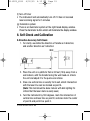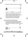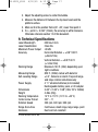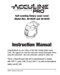
1
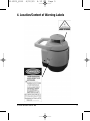
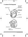
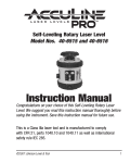
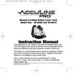
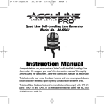
40-6520_6530
4/20/05
4:12 PM
Page 1
™
Self-Leveling Rotary Laser Level
Model Nos. 40-6520 and 40-6530
Instruction Manual
Congratulations on your choice of this Self-Leveling Rotary Laser
Level. We suggest you read this instruction manual thoroughly before
using the instrument. Save this instruction manual for future use.
This tool emits one rotating laser beam level line that is ideal for layout
of indoor or outdoor construction projects. Since the product is
equipped with a beam detector (in model no. 40-6530 only), visibility of
the beam in various lighting conditions is not an issue.
This is a Class IIIa laser tool and is manufactured to comply
with CFR 21, parts 1040.10 and 1040.11 as well as international
safety rule IEC 285.
©2005 Johnson Level & Tool
1
40-6520_6530
4/20/05
4:12 PM
Page 2
Table of Contents
1. Kit Contents
2. Features and Functions
3. Safety Instructions
4. Location/Content
of Warning Labels
5. Location of Parts/Components
6. Operating Instructions
7. Using the Product
8.
9.
10.
11.
12.
13.
14.
Self-Check and Calibration
Technical Specifications
Application Demonstrations
Care and Handling
Product Warranty
Product Registration
Accessories
1. Kit Contents
For Model No. 40-6520
Description
Self- Leveling Rotary Laser Level
Ni-MH Rechargeable Battery Pack
“C” Alkaline Battery Holder (batteries not included)
6V Battery Adapter
Vertical Mounting Adapter
Tinted Glasses
Instruction Manual with Warranty Card
Hard Shell Carrying Case
For Model No. 40-6530
Description
Self- Leveling Rotary Laser Level
Ni-MH Rechargeable Battery Pack
“C” Alkaline Battery Holder (batteries not included)
6V Battery Adapter
Vertical Mounting Adapter
Tinted Glasses
Detector with 9V Battery and Quick Clamp
Instruction Manual with Warranty Card
Hard Shell Carrying Case
2
Qty.
1
1
1
1
1
1
1
1
Qty.
1
1
1
1
1
1
1
1
1
©2005 Johnson Level & Tool
40-6520_6530
4/20/05
4:12 PM
Page 3
2. Features and Functions
• Magnetic dampening compensation system.
• Laser flashes and sounds alarm when product is not within
leveling tolerance.
• Projects a horizontal rotating plane with one up plumb beam.
• Projects a vertical rotating plane with one horizontal beam.
• Optional scan range from small to large providing user visible
chalk line.
• Adjustable scan orientation.
• Adjustable scan speed.
• Long battery life. Applicable for both alkaline batteries and
rechargeable battery-pack.
• Dust and rain resistant.
3. Safety Instructions
Please read and understand all of the following instructions, prior
to using this tool. Failure to do so, may result in bodily injury.
CAUTION: If using this product with any type of tinted goggles,
please note safety warning below.
DANGER!
Class IIIa Laser Product
Max. Power Output: ≤ 5mW
Wavelength: 625-645nm
THIS TOOL EMITS LASER RADIATION.
DO NOT STARE INTO BEAM.
AVOID DIRECT EYE EXPOSURE.
©2005 Johnson Level & Tool
3
40-6520_6530
4/20/05
4:12 PM
Page 4
ATTENTION
IMPORTANT
• Read all instructions prior to operating this laser tool. Do not remove any labels from
tool.
• Use of controls or performance of procedures other than those specified herein may
result in hazardous radiation exposure.
• Do not stare directly at the laser beam.
• Do not project the laser beam directly into the eyes of others.
• Do not set up laser tool at eye level or operate the tool near a reflective surface as
the laser beam could be projected into your eyes or into the eyes of others.
• Do not place the laser tool in a manner that may cause someone to unintentionally
look into the laser beam. Serious eye injury may result.
• Do not operate the tool in explosive environments, i.e. in the presence of gases or
flammable liquids.
• Keep the laser tool out of the reach of children and other untrained persons.
• Do not attempt to view the laser beam through optical tools such as telescopes as
serious eye injury may result.
• Always turn the laser tool off when not in use or left unattended for a period of time.
• Remove the batteries when storing the tool for an extended time (more than 3 months)
to avoid damage to the tool should the batteries deteriorate.
• Do not attempt to repair or disassemble the laser tool. If unqualified persons attempt
to repair this tool, serious injury may result.
• Use only original AccuLine Pro™ parts and accessories purchased from your AccuLine
Pro authorized dealer. Use of non-AccuLine Pro parts and accessories will void warranty.
WARNING!
The tinted goggles are designed to enhance
the visibility of the laser beam. They DO NOT
offer protection to the eyes from direct exposure
of the laser beam.
4
©2005 Johnson Level & Tool
40-6520_6530
4/20/05
4:12 PM
Page 5
4. Location/Content of Warning Labels
©2005 Johnson Level & Tool
5
40-6520_6530
4/20/05
4:12 PM
Page 6
5. Location of Part/Components
Operation Panel
Vertical Plumb
Laser Beam
Output Widnow
Rotating Laser
Output Widow
Handle
Bubble
Lock/Unlock
Locking Knob
Battery Box
Jack for
Adjusting Knob
6
DC 6V Power Jack
©2005 Johnson Level & Tool
40-6520_6530
4/20/05
4:12 PM
Page 7
6. Operating Instructions
IMPORTANT: It is the responsibility of the user to verify the calibration
of the instrument before each use.
Battery Installation
Note: Always check to be sure that the on/off switch is in the off
position before removing and replacing batteries.
Battery kit:
• “C” alkaline battery box
• Rechargeable battery-pack
Bolt
Alkaline Battery
Box
1. Loosen the set-bolt and take the battery box apart from the unit,
as shown in fig. a.
2. Put in four “C” batteries (not included) according to the polarity
illustrated in the battery box, and snap the battery box back into
place, as shown in fig. b and c.
3. If using the rechargeable battery-pack, fix the battery-box onto the
unit directly, and tighten the bolt (fig. c).
©2005 Johnson Level & Tool
7
40-6520_6530
4/20/05
4:12 PM
Page 8
Note:
• For the first two charges of new battery pack, it is necessary to
charge for 12-plus hours.
• After having been fully charged, we suggest that users should
charge for 2 more hours to ensure battery-pack's capacity.
• The instrument can still work even if it is being charged with
adapter.
• Do not charge alkaline batteries to avoid explosion.
• Used (discharged) batteries are hazardous waste and should be
disposed of properly.
Instrument Usage
1. Put in Ni-MH battery pack or alkaline batteries, or connect with 6V
DC power through power jack.
2. Place the instrument on platform or tripod, and connect with tripod
through 5/8" thread at the bottom of instrument.
Note: If instrument is inclined beyond the self-leveling range, it will
deliver an audible alarm. Re- position the instrument until leveled.
3. Rotate locking knob counter-clockwise to unlock, then turn power
on, and press the keys on control panel to adjust to your desired
working status.
4. After finishing operation or before moving the instrument, proceed
to turn power off and return locking knob to the locked position.
8
©2005 Johnson Level & Tool
40-6520_6530
4/20/05
4:12 PM
Page 9
7. Using the Product
Operating Panel
Range Scan
Indicator Lamp
Power Indicator
Lamp
Range Scan
Mode Button
On/Off Button
Down Button
Up Button
1. On/Off Button
• Pressing the button will turn the unit on / off.
2. Power Indicator Lamp
• Lit indicator lamp means power-on.
• Unlit indicator lamp means power-off.
• Flashing indicator lamp means low voltage.
3. Range scan Indicator Lamp
• Stable indicator lamp means continuous scan.
• Flashing indicator lamp means range scan.
4. Range scan mode button
• With the first press of this button, the instrument emits a short
bright horizontal laser line.
• With a second press of this button, the instrument emits a long
bright horizontal laser line.
• With a third press of this button, the instrument emits a bright
laser point.
• With a fourth press of this button, the laser will once again
rotate at high speed.
©2005 Johnson Level & Tool
9
40-6520_6530
4/20/05
4:12 PM
Page 10
5 and 6. Up/Down button
In continuous scan mode
• Press to increase scan speed
• Press to decease scan speed
In range scan mode
• Press to make the scanned range rotate clockwise
• Press to make the scanned range rotate counterclockwise
Usage for horizontal output status
• Reference “Instrument Usage” previously discussed
Usage for vertical output status
IMPORTANT: Keep “Locking Knob” in the “Locked” position.
1. Install batteries/battery pack as previously discussed.
2. Insert the “Adjusting knob” and place the instrument horizontally
on a stable platform (see fig. 5) or mount it on the tripod with
vertical mount.
3. Turn the “Adjusting Knob” until the bubble is centered.
4. Power on and select
Leveling Vial
the work state that you
need by pressing the
mode button on the
operating panel.
Handle
5. Power the instrument off
when you finish work or
make any movement. Adjusting
Knob
Vertical
Mount
10
©2005 Johnson Level & Tool
40-6520_6530
4/20/05
4:12 PM
Page 11
Detector Usage (included in Model No. 40-6530 only)
1. Technical Specifications
Detecting range
≥820 ft. (250m)
Detecting accuracy Fine
±0.039" (±1mm)
Coarse ±0.098" (±2.5mm)
Turn-off time
5 minutes
Operating voltage DC9V
Size
6-3/4" x 3" x 1" (0.266 x 0.118 x 0.029mm)
Weight
0.55 Ibs (0.249 Kg)
Dust and rain resistant
Illuminated Screen
Multi-functional double sides display
Buzzer for recognizing location
2. Components
(a) Structure
1. Display window
2. Level vial
3. Coarse/Fine detection button
4. Buzzer
5. Power button
6. Sound button
7. Illuminator button
8. Receiving window
9. Reverse display window
10. Reference rabbet
11. Location hole
12. Threaded hole
13. Battery-box cap
©2005 Johnson Level & Tool
11
40-6520_6530
4/20/05
4:12 PM
Page 12
(b) Display
1. Power symbol
2. Low battery symbol
3. Coarse/Fine detection symbol
4. Sound symbol
5. Detecting position symbol
3. Operation Guide
(a) Installation of battery
• Open the battery-box cap
• Put the 9V battery into the battery-box. Please note the polarity.
Then close the battery-box cap.
Note: Take the battery out if the instrument is not use for a long time.
(b) Turn on/off
• Press the power button. When Power symbol is
displayed, the instrument is ready for coarse
detection.
• When low battery symbol is displayed, change
the battery.
• Press the power button again to turn off the
instrument.
12
©2005 Johnson Level & Tool
40-6520_6530
4/20/05
4:12 PM
Page 13
(c) Using the clamp holder
1. clamp bolt
2. button
3. M5 screw
(d) Detection
1. Coarse detection
• Aim the receiving window at the
rotating laser instrument. Loosen the
clamp bolt and move the instrument
up and downwards to receive the
laser scanning signals transmitted by
the rotating laser instrument.
• When the instrument displays like
Fig. (A), move the instrument slightly
downwards as indicated by the arrow.
When it displays like Fig. (B), move it
slightly upwards as indicated by the
arrow.
• When Fig. (C) is displayed, the instrument is at the right position.
• Tighten the clamp bolt and mark the position of the object on the
rabbet. This mark will be the horizontal reference of the coarse
detection.
©2005 Johnson Level & Tool
13
40-6520_6530
4/20/05
4:12 PM
Page 14
2. Fine detection
1. power symbol
2. fine detection symbol
• Press coarse/fine detection button. The
instrument is ready for fine detection.
• Move the instrument slightly up and
downwards like the coarse detection
procedure.
• When the instrument displays as shown
in the figure, it is at the right position.
• Tighten the clamp bolt and mark the position of the object on the
rabbet. This mark will be the horizontal reference of the fine detection.
(e) Sound function
• If the instrument is working in a circumstance that makes it difficult
to use the display function, the sound function can be used instead.
• Press the sound function button. The sound symbol is displayed
which means it is ready for sound function. The instrument then
conducts coarse/fine detection through sound (buzz) signals.
• When the sound signal is ultra-short buzz, move the instrument
slightly upwards.
• When the instrument makes short buzz, move it slightly downwards.
• When the instrument makes intermittent, continuous sound, it is at
the right position.
• If there is no buzz heard, the instrument has not received the laser
scanning signal.
14
©2005 Johnson Level & Tool
40-6520_6530
4/20/05
4:12 PM
Page 15
(f) Turn-off timer
• The instrument will automatically turn off if it has not received
laser scanning signal for 5 minutes
(g) Illuminator system
• There is an illuminator system at the right-faced display window.
Press the illuminator button which will illuminate the display window.
8. Self-Check and Calibration
X-Direction Accuracy Self-Check
1. For clarity, we define the direction of handle as X-direction,
and another direction as Y-direction
Wall
2. Place the unit on a platform that is 30 feet (10m) away from a
wall indoors, with the handle facing the wall head-on. Unlock
the unit and adjust it to the quick-scan status.
3. Draw one vertical line on exactly front wall, which intersection
with the laser line can be marked as point A.
(Note: This test should be done indoors with dim lighting It’s
critical that the laser mark is easily seen)
4. Turn the instrument by 180 degrees, mark the intersection of
vertical line and laser line as point B, and also mark the center
of point A and point B as point 0.
©2005 Johnson Level & Tool
15
40-6520_6530
4/20/05
4:12 PM
Page 16
5. Measure the vertical distance h between point A and point B.
Wall
6. As shown, turn the instrument by 90° and place it on the
platform, with the operating panel facing you. Perform
Y-direction self-check with the same method as X-direction
self-check, and mark point C and point D by turns.
7. If h<0.236" (6mm), the accuracy is within tolerance.
Otherwise reference section 12 of this document.
Accuracy Self-Check for Vertical Output Status
1. Follow the operations as above, and measure the distance H1
between the laser rotating plane and the platform surface.
2. Set the locking knob to locking position, and place the instrument
horizontally.
Wall
16
©2005 Johnson Level & Tool
40-6520_6530
4/20/05
4:12 PM
Page 17
3. Adjust the adjusting screw to center the bubble.
4. Measure the distance H2 between the top laser beam and the
platform surface.
5. Mark out E in the position that is (H1 –H2 ) lower than point 0.
6. If e – point 0 < 0.394" (10mm), the accuracy is within tolerance.
Otherwise reference section 12 of this document.
9. Technical Specifications
Laser Wavelength
Laser Classification
Maximum Power Output
Accuracy
Working Range
Measuring Range
Self-Leveling Range
Power Supply
Dimensions
Weight
Working Temperature
Center screw thread
Rotation Speed
Range Scan Area
Enclosure
©2005 Johnson Level & Tool
635nm±10nm
Class IIIa
≤5mW
Horizontal Rotation = ±3/8"/100 ft.
(±3mm/10m)
Vertical Rotation = ±5/8"/100 ft.
(± 5mm/10m)
Maximum 100 ft. (30m) depending upon
light conditions
820 ft. (250m) radius with detector
±3.5°, Delivers an alarm if beyond range,
and stops rotation simultaneously
4 “C” alkaline batteries (not included)
Rechargeable battery pack, or 6V adapter
5-3/4" x 7-3/4" x 7-5/8" (146 x 197 x 194mm)
4.4lbs (2Kg)
14°F to 113°F (-10°C to +45°C)
5/8" – 11
300 rpm, 600 rpm, 900 rpm
Continuous, small range, large range, point
Dust and rain resistant
17
40-6520_6530
4/20/05
4:12 PM
Page 18
10. Application Demonstrations
18
Plumb reference
for ceiling installation
Reference for wall or
footing construction
Reference for squaring
and leveling
Reference for baseboard
installation
Reference for fence
installation
Reference for cement
floor installation
Reference for window
installation
Reference for anti-static
flooring installation
©2005 Johnson Level & Tool
40-6520_6530
4/20/05
4:12 PM
Page 19
11. Care and Handling
• This
laser unit is a precision tool that must be handled with care.
exposing unit to shock vibrations and extreme temperatures.
• Before moving or transporting the unit, make sure that the unit
is turned off and in the locked position. Failure to lock before
transport or storage may cause damage to the units inner
mechanism and void warranty.
• Remove the batteries when storing the unit for an extended time
(more than three months) to avoid damage to the unit should
the batteries deteriorate.
• Always store the unit in its case when not in use.
• Avoid getting the unit wet.
• Keep the laser unit dry and clean, especially the laser output
window. Remove any moisture or dirt with a soft, dry cloth.
• Do not use harsh chemicals, strong detergents or cleaning solvents
to clean the laser unit.
• Avoid
12. Product Warranty
Johnson Level & Tool offers a one year limited warranty on each its
products. You can obtain a copy of the limited warranty for a
Johnson Level & Tool product by contacting Johnson Level & Tool's
Customer Service Department as provided below or by visiting us
online at www.johnsonlevel.com. The limited warranty for each
product contains various limitations and exclusions.
Do not return this product to the store/retailer or place of purchase.
Required repair/calibration must be done by an authorized AccuLine
Pro™ service center or Johnson Level & Tool's limited warranty, if
applicable, will be void and there will be NO WARRANTY. Contact our
©2005 Johnson Level & Tool
19
40-6520_6530
4/20/05
4:12 PM
Page 20
Customer Service Department to obtain a Return Material
Authorization (RMA) number for return to an authorized service center.
Proof of purchase is required.
NOTE: The user is responsible for the proper use and care of the
product.
It is the responsibility of the user to verify the calibration of the
instrument before each use.
For further assistance, or if you experience problems with this product
that are not addressed in this instruction manual, please contact our
Customer Service Department.
In the U.S., contact Johnson Level & Tool’s Customer Service
Department at 800-563-8553.
In Canada, contact Johnson Level & Tool’s Customer Service
Department at 800-346-6682.
13. Product Registration
Enclosed with this instruction manual you will find a warranty card to be
completed for product warranty registration. Product warranty registration
can also be completed online at our web site www.johnsonlevel.com.
You will need to locate the serial number for your product that is located
on the bottom of the unit. PLEASE NOTE THAT IN ADDITION TO ANY
OTHER LIMITATIONS OR CONDITIONS OF JOHNSON LEVEL &
TOOL'S LIMITED WARRANTY, JOHNSON LEVEL & TOOL MUST
HAVE RECEIVED YOUR PROPERLY COMPLETED WARRANTY CARD
WITHIN 30 DAYS OF YOUR PURCHASE OF THE PRODUCT OR ANY
LIMITED WARRANTY THAT MAY APPLY SHALL NOT APPLY AND
THERE SHALL BE NO WARRANTY.
20
©2005 Johnson Level & Tool
40-6520_6530
4/20/05
4:12 PM
Page 21
14. Accessories
AccuLine Pro™ accessories are available for purchase through
authorized AccuLine Pro dealers. Use of non-AccuLine Pro accessories
will void any applicable limited warranty and there will be NO WARRANTY.
If you need any assistance in locating any accessories, please contact
our Customer Service Department.
In the U.S., contact Johnson Level & Tool’s Customer Service
Department at 800-563-8553.
In Canada, contact Johnson Level & Tool’s Customer Service
Department at 800-346-6682.
©2005 Johnson Level & Tool
21