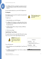
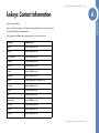
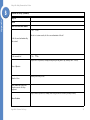
1
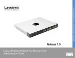
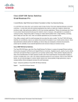
LINKSYS SGE2000/SGE2000P GIGABIT ETHERNET SWITCH ¸ Release 1.0 Linksys SGE2000/SGE2000P Gigabit Ethernet Switch Administration Guide © 2007 Cisco Systems, Inc. Specifications are subject to change without notice. Linksys, the Cisco Systems logo, the Linksys Logo, and the Linksys One logo are registered trademarks of Cisco Systems, Inc. All other trademarks mentioned in this document are the property of their respective owners. Linksys One Ready Communications Solution Contents Chapter 1: Introduction - - - - - - - - - - - - - - - - - - - - - - - - -1 What’s in this User Guide? Chapter 2: Getting to Know the Switch Overview The Front Panel Front Panel LEDs LAN Port LEDs Uplink Port LEDs Stack ID LEDs Reset Switch LAN Ports Uplink Ports The Back Panel Power Port Console Port RPS Port 1 - - - - - - - - - - - - - - - - -3 3 3 3 4 4 5 5 5 6 6 7 7 7 Chapter 3: Connecting the Switch - - - - - - - - - - - - - - - - - - - -8 Overview Before You Install the Switch... Placement Options Desktop Placement Rack-Mount Placement Wall-Mount Placement Connecting the Cables Stacking Multiple Switches Connecting Cabling for Stacking 8 8 9 9 9 10 10 12 13 Chapter 4: Console Configuration - - - - - - - - - - - - - - - - - - - 14 Overview Configuring the HyperTerminal Application 14 14 i Linksys One Ready Communications Solution Connecting to the Switch using Telnet or SSH Configuring the Switch through the Console or Telnet Interface Switch Main Menu 16 16 17 Chapter 5: Web Utility Configuration - - - - - - - - - - - - - - - - - 31 Overview Accessing the Web-based Utility Viewing Online Help 31 31 31 Appendix A: Linksys Contact Information - - - - - - - - - - - - - - - 32 Appendix B: Customer Site Survey - - - - - - - - - - - - - - - - - - 34 Appendix C: Limited Warranty - - - - - - - - - - - - - - - - - - - - 37 Appendix D: Federal Communication Commission Interference Statement 39 Industry Canada Statement EC Declaration of Conformity (Europe) 39 39 Appendix E: Specifications - - - - - - - - - - - - - - - - - - - - - - 40 ii Linksys One Ready Communications Solution Chapter 1 Introduction Welcome Thank you for choosing a Linksys Ethernet switch. This Ethernet switch allows you to quickly and easily expand your Linksys One system. It delivers non-blocking, wire speed switching for your network clients, plus multiple options for connecting to your network backbone. Twenty four ports wire up your workstations or connect to other Linksys switches or devices. LED indicators provide power, link, and activity status. Linksys One Portal The Ethernet switch features monitoring and configuration via the Linksys One Portal, your web browser, or the console interface. If your Ethernet switch is part of a Linksys One system, the easiest way to manage it is with the Linksys One Portal — available only on the Linksys One Services Router. Refer to the Linksys One Customer Premises Equipment Administration Guide for more details on the Linksys One Portal. The Ethernet switch supports numerous security features including the Remote Authorization and Authentication (RADIUS) and Terminal Access Controller Access Control System (TACACS+) protocols. With Simple Network Time Protocol (SNTP), the Ethernet switch can synchronize its clock with a time server available on one of its attached networks. The system is fully manageable using a combination of a database of MIB (Management Information Base) variables, whose combined values represent all facets of the system state, and the Simple Network Management Protocol (SNMP) protocol. The “P” model of the Ethernet switch supports Power over Ethernet (PoE) which eliminates the need to run 110/220 VAC power to wireless network, IP telephony, or other PoE powered devices on the Linksys network. Use of a PoE system allows greater flexibility in locations of network devices, and significantly decreasing installation costs. The entire PoE system can be centrally powered by uninterruptible power supplies if necessary. What’s in this User Guide? This user guide covers the steps for setting up and using the Ethernet switch. Use the instructions in this guide to help you connect the switch, set it up, and configure it to your Linksys network. These instructions should be all you need to get the most out of your Ethernet switch. Chapter 1: Introduction What’s in this User Guide? 1 Linksys One Ready Communications Solution 1 This user guide contains the following chapters: Chapter 1, "Introduction" Chapter This chapter describes the Ethernet switch applications and provides an overview of the content of this administration guide. Chapter 2, "Getting to Know the Switch" This chapter describes the physical features of the Ethernet switch. Chapter 3, "Connecting the Switch" This chapter explains how to install and connect the Ethernet switch. Chapter 4, "Console Configuration" This chapter describes how to use the console interface when you configure the Ethernet switch. Chapter 5, "Web Utility Configuration" This chapter shows you how to configure the Ethernet switch using the Web-based Utility. 2 Chapter 1: Introduction What’s in this User Guide? Linksys One Ready Communications Solution Chapter 2 Getting to Know the Switch Overview The SGE2000 and SGE2000P models are 24-port, layer-2 Ethernet switches that expand the capability of the Linksys system. These two versions are functionally identical except the SGE2000P model offers Power-over-Ethernet (PoE) which can be used to supply power to various Linksys products over Ethernet cable. 1 System Status LEDs. Four LEDs indicate the status of the Ethernet switch power, fan, RPS connectivity, and stack master. For more details, refer to ”System Status LEDs,” on page 4. 2 LAN Ports. Twenty four 10/100/1000 BaseT LAN ports provide connectivity to other Linksys devices. For more details, refer to ”LAN Ports,” on page 5. 3 Gigabit Interface Converter (mini-GBIC) Uplink Ports. Four mini-GBIC ports provide uplink ports which support network speeds of 10Mbps, 100Mbps, and 1000Mbps. For more details, refer to ”Uplink Ports,” on page 6. 4 Stack ID. If stacking is active, indicates the ID number of the stack. For more details, refer to ”Stack ID LEDs,” on page 4. 5 RESET Switch. Resets the SGE2000/SGE2000P Ethernet switch. For more details, refer to ”Reset Switch,” on page 5. The Front Panel The Switch's LEDs and Ethernet ports are located on the front panel. 1 2 3 4 5 Front Panel LEDs The Switch uses Light Emitting Diodes (LEDs) to indicate the status of numerous functions. These functions are listed below. Chapter 2: Getting to Know the Switch Overview 3 Linksys One Ready Communications Solution 2 System Status LEDs A green PWR LED lights to indicate that the Ethernet switch is powered by internal power supplies. If the Ethernet switch is powered by a remote power supply (RPS), this LED blinks red. FAN A green FAN LED lights to indicate that the cooling fan is operating properly. A blinking red FAN LED indicates that the cooling fan has failed. RPS A green RPS LED lights to indicate that RPS is connected and operating properly. A blinking red RPS LED indicates an RPS fault. MST A green MST LED indicates that this Ethernet switch is a stack master. Chapter PWR LAN Port LEDs Act/Link The green Act/Link LEDs light to indicate a functional network link through the corresponding port with an attached device. The Act (Activity) LEDs flash to indicate that the Ethernet switch is actively sending or receiving data over that port. Uplink Port LEDs Act/Link The green Act/Link LEDs light to indicate a functional network link through the corresponding port with an attached device. The Act (Activity) LEDs flash to indicate that the Ethernet switch is actively sending or receiving data over that port. Gigabit The Gigabit LED lights indicate a Gigabit connection on the corresponding port. Stack ID LEDs Stack ID 4 A green Stack ID LED indicates that this Switch is stacked and the corresponding number indicates its stack ID. Range is 1 to 8. Chapter 2: Getting to Know the Switch The Front Panel Linksys One Ready Communications Solution Chapter 2 Reset Switch The Ethernet switch can be reset by inserting a pin or paper clip into the RESET opening. If the reset switch is held for 10 seconds or longer, the Ethernet switch will be reset to its default settings. CAUTION: All user-defined settings are lost when you hold the Reset button for 10 seconds or longer; the Ethernet switch reverts to its default settings. When a unit is reset to its default setting, the unit restarts in stackable mode using default stacking ports with autonumbering enabled. Pressing the reset button on the master unit of a stack resets all units in the stack. LAN Ports The Ethernet switch is equipped with 24 Ethernet ports. 1-24 The Switch is equipped with 24 auto-sensing, Ethernet (IEEE 802.3) network ports, which use RJ-45 connectors. The Gigabit Ethernet ports support network speeds of 10Mbps, 100Mbps, and 1000Mbps. They can operate in half and full-duplex modes. Auto-sensing technology enables each port to automatically detect the speed of the device connected to it, and adjust its speed and duplex accordingly. In stacking mode, two ports are used for stacking. By default, the stacking ports are 12 and 24. Ports 11, 12, 23, and 24 are shared with GBIC1, GBIC3, GBIC2, GBIC4 respectively. If shared port pairs are both connected, then the mini-GBIC port takes priority. Chapter 2: Getting to Know the Switch The Front Panel 5 Linksys One Ready Communications Solution 2 Uplink Ports The Switch is equipped with 4 mini-GBIC uplink ports. Chapter GBIC1-4 The Switch provides four mini-GBIC ports. The mini-GBIC port is a connection point for a mini-GBIC expansion module, so the Switch can be uplinked via fiber or copper to another switch. Each mini-GBIC port provides a link to a high-speed network segment or individual workstation at speeds of up to 1000Mbps. Use the Linksys MGBT1, MGBSX1, or MGBLH1 mini-GBIC modules with the Switch. The MGBSX1 and the MGBLH1 require fiber cabling with LC connectors, while the MGBT1 requires a Category 5e Ethernet cable with an RJ-45 connector. The Back Panel 1 Power Port. The Power port is where you will connect the power cord. For more details, refer to ”Power Port,” on page 6. 2 Console Port. The Console port is where you can connect a serial cable to a PC’s serial port for configuration. For more details, refer to ”Console Port,” on page 7. 3 RPS Port. Redundant Power Supply (RPS) port. For more details, refer to ”RPS Port,” on page 7. The power port is located on the back panel of the Ethernet switch. 2 1 DC INPUT FOR REMOTE POWER SUPPLY SPECIFIED IN MANUAL +12V, 7.5A 3 Power Port The 100-240 VAC power cord is connected to the Power port. CAUTION: Only use the power cord that is supplied with the Ethernet switch. The unit may be damaged if the incorrect power cord is used. 6 Chapter 2: Getting to Know the Switch The Back Panel Linksys One Ready Communications Solution Chapter 2 Console Port The Console port is where you connect a serial cable to a PC’s serial port for configuration using your PC’s HyperTerminal program. Refer to ”Configuring the HyperTerminal Application,” on page 14 for more information. NOTE: Many modern laptop computers are not supplied with serial ports. You may use a USB-to-Serial adapter on your laptop to connect to the console serial port. RPS Port An optional Redundant Power Supply (RPS) is connected to the RPS port. An RPS enhances the reliability of the Ethernet switch and it can keep the unit running if a power failure occurs. Only use a Linksys RPS1000 Redundant Power Supply unit and a proper RPS cable (RPSCBL1) with the Ethernet switch. WARNING: Do not remove the cover from the RPS port unless an RPS unit is connected to the Ethernet switch. Keep the RPS port covered when not in use. Chapter 2: Getting to Know the Switch The Back Panel 7 Linksys One Ready Communications Solution 3 Connecting the Switch Chapter Overview This chapter will explain how to connect network devices to the Ethernet switch. For an example of a possible network configuration, see the application diagrams shown below. Before You Install the Switch... When you choose a location for the Ethernet switch, observe the following guidelines: • Make sure that the Ethernet switch will be accessible and that the cables can be easily connected. • Keep cabling away from sources of electrical noise, power lines, and fluorescent lighting fixtures. • Position the Ethernet switch away from water and moisture sources. • To ensure adequate air flow, be sure to provide a minimum clearance of two inches (50 mm) around the air intake and exhaust ports on the sides of the Ethernet switch. • Do not stack free-standing Ethernet switches more than four units high. The stacking configuration, described in ”Stacking Multiple Switches,” on page 12, allows up to eight 8 Chapter 3: Connecting the Switch Overview Linksys One Ready Communications Solution Chapter 3 units to be logically stacked together. It is recommended that multiple Ethernet switches be mounted in a rack when installed in this manner. Ethernet switches can be physically placed at different locations; they do not have to be stacked at the same location. Placement Options Before connecting cables to the Ethernet switch, first you will physically install the Ethernet switch. Either set the Ethernet switch on its four rubber feet for desktop placement, mount it in a standard-sized, 19-inch wide for rack-mount placement, or mount it on a wall with the wall-mount brackets provided. NOTE: The four supplied mounting brackets can be used for either wall mount or rack mount installations. Desktop Placement 1. Attach the rubber feet to the recessed areas on the bottom of the Ethernet switch. 2. Place the Ethernet switch on a desktop near an AC power source. CAUTION: Keep enough ventilation space for the Ethernet switch so it does not exceed the environmental restrictions mentioned in the specifications. Rack-Mount Placement To mount the Ethernet switch in any standard-sized, 19-inch wide, (each Ethernet switch requires 1RU of space in the rack), follow these instructions: 1. Remove the four front screws on one side of the Ethernet switch. Retain the screws for reinstallation. 2. Place one of the supplied spacers on the side of the Ethernet switch so the four holes align to the screw holes. Chapter 3: Connecting the Switch Placement Options 9 Linksys One Ready Communications Solution 3 3. Place a rack mount bracket next to the spacer and reinstall the four screws (removed in step 1). 4. Repeat steps 2 through 3 for the other side of the Ethernet switch. Chapter 5. Attach the Ethernet switch to the rack using the supplied screws. Wall-Mount Placement 1. On one of the side corners, remove the four front screws on of the Ethernet switch. Retain the screws for re-installation. NOTE: The Ethernet switch, shown below, is mounted with the ports located on top. When the switch is mounted to a wall, the ports can be oriented in any direction. 2. Place one of the supplied spacers on the side of the Ethernet switch so the four holes align to the screw holes. 3. Place a rack mount bracket next to the spacer and reinstall the four screws (removed in step 1). The wall mount brackets should point towards the bottom of the Ethernet switch. 4. Repeat steps 1 through 3 for the other corners of the Ethernet switch. 5. Attach the Ethernet switch to a wall with appropriate screws (not supplied). CAUTION: Ensure that the Ethernet switch is securely attached to the wall. 10 Chapter 3: Connecting the Switch Placement Options Linksys One Ready Communications Solution 3 Connecting the Cables Chapter To connect network devices to the Ethernet switch, follow these instructions: 1. For 10/100Mbps devices, connect a Category 5 Ethernet network cable to one of the numbered ports on the Ethernet switch. For a 1000Mbps device, connect a Category 5e Ethernet network cable to one of the uplink ports on the Ethernet switch. 2. Connect the other end to a PC or other network device. 3. Repeat steps 2 and 3 to connect additional devices. NOTE: If connecting an Ethernet switch to an SVR3000 router, connect it to a Cascade port on the SVR3000. 4. If you are using the mini-GBIC port, then insert the mini-GBIC module to the mini-GBIC port. For detailed instructions, refer to the documentation supplied with the mini-GBIC module. CAUTION: Observe the orientation of the mini-GBIC module before inserting it into a mini-GBIC port. The bottom miniGBIC ports are upside down in relation to the top mini-GBIC ports. 5. If you use the console interface to configure the Ethernet switch, then connect the supplied serial cable to the console port (located on the back of the Ethernet switch), and tighten the captive retaining screws. Connect the other end to your PC’s serial port. (The PC must be running VT100 terminal emulation software, such as HyperTerminal.) 6. Connect the supplied power cord to the power port, and plug the other end into an electrical outlet. CAUTION: Make sure you use the power cord that is supplied with the Ethernet switch. Use of a different power cord could damage the Ethernet switch. 7. Power on the network devices connected to the Ethernet switch. Each active port’s corresponding Act/Link LED will light up on the Ethernet switch. If a port has an active Gigabit connection, then its corresponding Gigabit LED will also light up. Chapter 3: Connecting the Switch Connecting the Cables 11 Linksys One Ready Communications Solution If you will use the console interface to configure the Ethernet switch, proceed to ”Console Configuration” section on page 14 for directions. 3 Stacking Highlights • In stacking mode, each Ethernet switch is given a unique ID, from 1 to 8. Stacking Multiple Switches • Stack IDs 1 and 2 are Master Enabled units. • All Ethernet switches in the stack must run the same version of software. • The Stack Master switch maintains the configuration. Devices support stacking up to eight Ethernet switches per stack, or can operate as standalone units. During the Stacking setup, the switches auto-select one of the switches as the Stacking Master. All other devices are named as slave stack members and assigned a unique Unit ID. One of the slave units is designated as the backup master. The backup master acts as a slave unit, but can become a stack master in the event of failure of stack master. The master and backup master are assigned unit IDs of 1 and 2. The Stack Master provides a single point of control and management as well as a single interface in which to control and manage the stack. • Stack cannot combine Linksys SFE2000 and SGE2000 family Ethernet switches. • By factory default, Ethernet switches boot in stacking mode. • Stack ID can be user assigned or automatically assigned. Switch software is downloaded separately for each stack member. However, all units in the stack must be running the same software version. • Stacking ports are available to user in standalone mode as regular network ports A stack unit can operate in one of the following modes: • Settings are applied only to the master unit; certain changes take place only after reset The Stacking configuration provides multiple switch management through a single point as if all stack master and slaves were a single Ethernet switch. All stack masters are accessed through a single IP address through which the stack is managed. The stack can be managed from the the web-based interface or the console interface. 12 • Stand-alone — The unit runs as a standard switch and does not run the stacking application. • Master Unit — Manages the Stack and is responsible for the configuration. • Master-Backup — Runs as a slave unit and monitors the operation of the stack master. • Slave — Runs a slave version of the switching algorithm, which allows the applications running on the master unit to control the resources of the slave unit. Chapter 3: Connecting the Switch Stacking Multiple Switches Chapter If you use the Web-based Utility to configure the Ethernet switch, proceed to ”Web Utility Configuration” section on page 31. Linksys One Ready Communications Solution Chapter 3 By default, the Ethernet switch is in stacking mode. Using the console interface or the web interface, you can change the mode to standalone mode. TIP: Power the Ethernet switches in the order that you want them in the Stack ID. The first powered Ethernet switch in a stack is assigned as the Master Unit, the next powered unit is assigned as the Master-Backup. The remaining units are assigned Stack IDs in the order that they are powered. When the device is in standalone mode, the stacking ports can be used as regular ports. Connecting Cabling for Stacking When the Ethernet switch is in stacking mode, ports 12 and 24 are reserved as stacking ports and cannot be used as network ports. Ports GBIC3 and GBIC4 can also be used as stacking ports. Chapter 3: Connecting the Switch Stacking Multiple Switches 13 Linksys One Ready Communications Solution 4 Console Configuration Chapter Overview The Ethernet switch features a menu-based console interface for basic configuration of the Ethernet switch and management of your network. The Ethernet switch can be configured using a menu-based interface through the console port or through a telnet connection. This chapter describes console interface configuration. Configuration can also be performed through the web utility, which is covered in the next chapter. NOTE: The Ethernet switch is setup by default to obtain its IP address via DHCP on the default VLAN 100. Configuring the HyperTerminal Application Before you use the console interface, you will need to configure the HyperTerminal application on your PC. 1. Click the Start button. 2. Select Programs and choose Accessories. Select Communications. 3. Select HyperTerminal from the options listed in this menu. 4. On the Connection Description screen, enter a name for this connection. In the example, the name of connection is Linksys One. 5. Select an icon for the application. Then, click the OK button. 14 Chapter 4: Console Configuration Overview Linksys One Ready Communications Solution Chapter 4 6. On the Connect To screen, select a port to communicate with the Ethernet switch. 7. Set the serial port settings as follows: • Bits per second: 115200 • Data bits: 8 • Parity: None • Stop bits: 1 • Flow control: None Then, click the OK button. Chapter 4: Console Configuration Configuring the HyperTerminal Application 15 Linksys One Ready Communications Solution 4 Connecting to the Switch using Telnet or SSH Chapter If you know the IP address of your Ethernet switch (obtained from your DHCP server or the console interface), you can connect to the switch through a Telnet session. 1. Use your preferred Telnet or Secure Shell Client application, for example HyperTerminal or the Telnet application available throught a Windows command window. 2. Open a telnet session using the IP address of your Ethernet switch. For example: telnet 192.168.100.21. The Login screen will appear. 3. Type the user name and password. 4. Press the Enter key. Configuring the Switch through the Console or Telnet Interface The management screens consist of a series of menus. Each menu has several options, which are listed vertically. You select a menu option when you highlight it; pressing the Enter key activates the highlighted option. To navigate through the menus and actions of the console interface, use the up or down arrow keys to move up or down, and use the left or right arrow keys to move left or right. Use the Enter key to select a menu option, and use the Esc key to go to the action menu. Menu options and any values entered or present are highlighted. The bottom of the screen lists the actions available. 16 Chapter 4: Console Configuration Connecting to the Switch using Telnet or SSH Linksys One Ready Communications Solution Chapter 4 Switch Main Menu The System Main Menu screen displays these choices: 1. System Configuration Menu 2. Port Status 3. Port Configuration 4. System Mode (Layer 2 / Layer 3) Selection 5. Help System Configuration Menu On the System Configuration Menu screen, you have these choices: 1. System Information 2. Management Settings 3. User & Password Settings 4. Security Settings 5. IP Configuration 6. File Management 7. Restore System Default Settings 8. Reboot System 9. Stack Configuration 0. Back to main menu System Information Use this screen to check firmware versions and general system information for the Ethernet switch. Chapter 4: Console Configuration Configuring the Switch through the Console or Telnet Interface 17 Linksys One Ready Communications Solution 4 Versions Chapter Use the Versions screen to display the boot, software, and hardware firmware versions of the Ethernet switch. In stacking mode, This information is displayed for the stack master. General System Information Use the General System Information screen to display the description, System Up Time, System MAC Address, System Contact, System Name, and System Location of the Ethernet switch. To change general system information: a. Select Edit to make changes. b. When your changes are complete, press the Esc key to return to the Action menu c. Select Save to save your changes. Management Settings From the Management Settings screen, you can set Serial Port Session Configuration, Telnet Session Configuration, or Secure Telnet (SSH) Configuration. 18 Chapter 4: Console Configuration Configuring the Switch through the Console or Telnet Interface Linksys One Ready Communications Solution Chapter 4 Serial Port Configuration Use the Serial Port Configuration screen to display the baud rate of the Ethernet switch. To change the baud rate of the serial port: a. Select Edit to make changes. b. When your changes are complete, press the Esc key to return to the Action menu. c. Select Save to save your changes. Telnet Configuration Use the Telnet Configuration screen to display the time-out settings. To change the time-out setting: a. Select Edit to make changes. b. When your changes are complete, press the Esc key to return to the Action menu. c. Select Save to save your changes. Chapter 4: Console Configuration Configuring the Switch through the Console or Telnet Interface 19 Linksys One Ready Communications Solution 4 SSH Configuration Use the SSH Configuration screen to configure and display SSH settings. Chapter SSH Server Configuration: Use the SSH Server Configuration screen to enable or disable the SSH server, and to configure the port over which the SSH session is enabled. To change SSH Server settings: a. Select Edit to make changes. b. When your changes are complete, press the Esc key to return to the Action menu. c. Select Save to save your changes. SSH Status: Use the SSH Status screen to view information about SSH sessions. SSH Crypto Key Generation: Use the SSH Crypto Key Generation screen to generate an SSH RSA or DSA key. To change SSH Crypto Key Generation settings: a. Select Edit to make changes. b. When your changes are complete, press the Esc key to return to the Action menu. c. Select Save to save your changes. 20 Chapter 4: Console Configuration Configuring the Switch through the Console or Telnet Interface Linksys One Ready Communications Solution SSH Keys Fingerprints: Use the SSH Keys Fingerprints screen to view the RSA and SSA fingerprints. Chapter 4 User & Password Settings The User & Password Settings screen lets you specify user names and passwords for the Ethernet switch. Up to 5 users can be assigned. NOTE: The default user is “admin” with no password. There is also a special user defined by default for internal use by the Linksys system (l1_admin). For support reasons, it is recommended that you not delete this user. To change User & Password settings: a. Select Edit to make changes. b. When your changes are complete, press the Esc key to return to the Action menu. c. Select Save to save your changes. Chapter 4: Console Configuration Configuring the Switch through the Console or Telnet Interface 21 Linksys One Ready Communications Solution 4 Security Settings The Security Settings screen enables you to configure security settings on the Ethernet switch, as well as generate and display the certificate. Chapter Use the SSL Certificate Generation screen to specify a device-generated certificate. The following fields are specified: Public Key Algorithm Specifies the SSL type Public Key Length Specifies the SSL RSA key length. (Range: 512 to 2048) Common Name (FQCN) IP address of the Ethernet switch Department Name Specifies the department name. (Range: 1 to 32 characters) Organization Name Specifies the organization name. (Range: 1 to 32 characters) Locality or City Name Specifies the location or city name. (Range: 1 to 32 characters) State or Province Name Specifies the state or province name. (Range: 1 to 32 characters) 22 Chapter 4: Console Configuration Configuring the Switch through the Console or Telnet Interface Linksys One Ready Communications Solution Chapter 4 Country Name Specifies the country name. (Range: 2 to 2) Validity Term Specifies number of days certification is valid. (Range: 30 to 3650) To change SSL Certificate Generation settings: a. Select Edit to make changes. b. When your changes are complete, press the Esc key to return to the Action menu. c. Select Save to save your changes. Show Certificate Use the Show Certificate screen to display the internal certificate. Disable Active Management Access Profile Disables the currently active management access profile. To disable the currently active management access profile: a. Type Y to verify that you want to disable the currently active management access profile. Chapter 4: Console Configuration Configuring the Switch through the Console or Telnet Interface 23 Linksys One Ready Communications Solution 4 IP Configuration The IP Configuration screen displays these choices: the IP Address Settings, HTTP, HTTPS Configuration, and Network Configuration of the Ethernet switch. Chapter IP Address Configuration (Layer 2) The IP information of the Ethernet switch is displayed here. IP Address The IP Address of the Ethernet switch is displayed. Verify that the address you enter is correct and does not conflict with another device on the network. Subnet Mask The subnet mask of the Ethernet switch is displayed. Default Gateway The IP address of your network’s default gateway is displayed. Management VLAN The VLAN ID number is displayed. DHCP client The status of the DHCP client is displayed. If you want the Ethernet switch to be a DHCP client, then select ENABLE. If you want to assign an static IP address to the Ethernet switch, then enter the IP settings and select DISABLE. IP Address Configuration (Layer 3) The IP information of the Ethernet switch is displayed here. IP Address The IP Address of the Ethernet switch is displayed. Verify that the address you enter is correct and does not conflict with another device on the network. Subnet Mask The subnet mask of the Ethernet switch is displayed. Interface Type The type of interface. Interface Number The number of the interface. 24 Chapter 4: Console Configuration Configuring the Switch through the Console or Telnet Interface Linksys One Ready Communications Solution Chapter 4 To change IP address configuration settings: a. Select Edit to make changes. b. When your changes are complete, press the Esc key to return to the Action menu. c. Select Save to save your changes. IP Address Table (Layer 3 Only) The IP Address Table screen lets you make changes ot the IP address table. To change the IP address table: a. Select Edit to make changes. b. When your changes are complete, press the Esc key to return to the Action menu. c. Select Save to save your changes. HTTP Configuration The HTTP screen displays the status and port number of the HTTP Server. To change HTTP settings: a. Select Edit to make changes. b. When your changes are complete, press the Esc key to return to the Action menu. c. Select Save to save your changes. HTTPS Configuration Use the HTTPS Configuration screen to configure HTTPS settings. You can enable or disable the HTTPS server and configure the port on which the session is enabled. To change HTTPS settings: a. Select Edit to make changes. b. When your changes are complete, press the Esc key to return to the Action menu. Chapter 4: Console Configuration Configuring the Switch through the Console or Telnet Interface 25 Linksys One Ready Communications Solution 4 c. Select Save to save your changes. Network Configuration Chapter The Network Configuration screen offers a choice of two tests, Ping and TraceRoute. Ping The Ping screen displays the IP address of the location you want to contact. Select Edit to change the IP address, and select Execute to begin the ping test. After the ping test is complete, the Ping screen displays the IP address, status, and statistics of the ping test. Select Edit to make changes. When your changes are complete, press the Esc key to return to the Action menu, and select Save to save your changes. TraceRoute The TraceRoute screen displays the IP address of the address whose route you want to trace. Select Edit to change the IP address, and select Execute to begin the traceroute test. After the traceroute test is complete, the TraceRoute screen displays the IP address, status, and statistics of the traceroute test. 26 Chapter 4: Console Configuration Configuring the Switch through the Console or Telnet Interface Linksys One Ready Communications Solution 4 Select Edit to make changes. When your changes are complete, press the Esc key to return to the Action menu, and select Save to save your changes. Chapter File Management The File Management screen allows you to upload or download files, such as the startup configuration, boot, or image file, using a TFTP server. NOTE: There are two software images on the Ethernet switch: Image 1 and Image 2. When you copy an image to the switch via TFTP, the inactive image is replaced. When you copy an image to the switch via the console port, the active image is replaced. Upgrade / Backup Select Edit to change the settings. Specify the source and destination of the file, the file name, and the IP address of the file server where the upgrade file is being downloaded, When your changes are complete, press the Esc key to return to the Action menu, and select Execute to upload or download the designated file. Active Image The Active Image screen shows information about the active image file and the image file that will be active after reboot. Chapter 4: Console Configuration Configuring the Switch through the Console or Telnet Interface 27 Linksys One Ready Communications Solution 4 Restore System Default Settings Chapter To set the Ethernet switch back to the factory default settings, select Restore System Default Settings and press the Enter key. You will be asked if you want to continue. Press the y key to restore the default settings, or press the n key to cancel. NOTE: Restoring default settings from the console, web, or Linksys One portal interfaces resets all values except stacking configuration (stacking mode, stacking ports, and auto-numbering settings are NOT reset). To reset stacking configuration, use the hardware reset button on the front of the Ethernet switch. Reboot System Select Reboot System and press the Enter key if you want to restart the Ethernet switch. You will be asked if you want to continue. Press the y key to reboot the Ethernet switch, or press the n key to cancel. After the Ethernet switch has rebooted, the Switch Main Menu screen will appear. Stack Configuration Select Stack Configuration to specify the Stack ID for the Ethernet switch. By default, ID numbers are automatically assigned to each device. Back to main menu Select Back to main menu and press the Enter key if you want to return to the Switch Main Menu screen. Port Status The Port Status screen displays the port connection status. To view the status of the ports: TIP: Use the up or down arrow keys to scroll through all the ports on the Ethernet switch. 1. On the Switch Main Menu screen, select Port Status. 28 Chapter 4: Console Configuration Configuring the Switch through the Console or Telnet Interface Linksys One Ready Communications Solution Chapter 4 2. Press the Enter key. The Port Status screen displays the port numbers, their status, Link status, speed and duplex mode, and status of flow control, which is the flow of packet transmissions. If you want to change any settings for a port, you must use the Port Configuration screen. Port Configuration The Port Configuration screen lets you specify the auto negotiation status, port speed, duplex mode, and flow control settings. To configure the ports: TIP: Use the up or down arrow keys to scroll through all the ports on the Ethernet switch. 1. On the Switch Main Menu screen, select Port Configuration. 2. Press the Enter key. The Port Configuration screen displays the port numbers, their status, auto-negotiation status, speed and duplex mode, and status of flow control, which is the flow of packet transmissions. 3. Select Edit to make changes. When your changes are complete, press the Esc key to return to the Action menu. 4. Select Save to save your changes. System Mode (Layer 2 / Layer 3) Selection The System Mode Selection screen lets you specify whether the Ethernet switch is operating in Layer 2 or Layer 3 mode. You can also configure stacking mode from this screen. IMPORTANT: If the Ethernet switch is being used as part of a Linksys One system, it must operate as a Layer 2 switch. To view or edit the system mode: 1. On the Switch Main Menu screen, select System Mode (Layer 2 / Layer 3) Selection Port Configuration. 2. Press the Enter key. The System Mode (Layer 2 / Layer 3) Selection screen displays the current system and stacking mode. Chapter 4: Console Configuration Configuring the Switch through the Console or Telnet Interface 29 Linksys One Ready Communications Solution 4 3. To edit these modes, select Edit to make changes. When your changes are complete, press the Esc key to return to the Action menu. 4. Select Save to save your changes. Chapter 5. Reboot the Ethernet switch. Your new settings will take effect after reboot. Help The Help screen lets you view information about how to navigate the Ethernet switch menus. To view help information: 1. Select Help. 2. Press the Enter key if you want to view the help information. This screen explains how to navigate the various screens of the console interface. Logout The Logout command lets you logout from the Ethernet switch. NOTE: When you issue this command, you are immediately logged off the Ethernet switch. To logout from the Ethernet switch: • 30 Select logout. Chapter 4: Console Configuration Configuring the Switch through the Console or Telnet Interface Linksys One Ready Communications Solution Chapter 5 Web Utility Configuration Overview The Linksys Switch provides a complete web-based utility to configure the Ethernet switch. This utility is accessible through your web browser. Use the navigation window, located on the left side of the web-based utility, to view various functions of the Ethernet switch. NOTE: The Ethernet switch is setup by default to obtain its IP address via DHCP on the default VLAN 100. Accessing the Web-based Utility To access the web-based utility, enter the IP address of the Ethernet switch to the address field of your web browser. For example: type http://192.168.100.20 or https://192.168.100.20 if the IP address of the Ethernet switch is 192.168.100.20. The IP address of the Ethernet switch is determined by DHCP, so you’ll need to find its address using the Console configuration or the Linksys One Administrator screen. Linksys One Portal If your Ethernet switch is part of a Linksys One system, the easiest way to manage it is with the Linksys One Portal — available only on the Linksys One Services Router. Refer to the Customer Premises Equipment Administration Guide for more details on the Linksys One Portal. Viewing Online Help The Web Utility has complete online help functionality for each screen. To access on-line help for a particular screen, click on the Help button located on the right side of the screen. Chapter 5: Web Utility Configuration Overview 31 Linksys One Ready Communications Solution A Linksys Contact Information Appendix Need to contact Linksys? Visit us online for information on the latest products and updates to your existing products at: http://www.linksys.com/international If you experience problems with any Linksys product, you can e-mail us at: In Europe E-mail Address Austria [email protected] Belgium [email protected] Czech Republic [email protected] Denmark [email protected] Finland [email protected] France [email protected] Germany [email protected] Greece [email protected] (English only) Hungary [email protected] Ireland [email protected] Italy [email protected] Netherlands [email protected] Norway [email protected] Poland [email protected] Portugal [email protected] 32 Appendix A: Linksys Contact Information Linksys One Ready Communications Solution Appendix A In Europe E-mail Address Russia [email protected] Spain [email protected] Sweden [email protected] Switzerland [email protected] United Kingdom [email protected] Outside of Europe E-mail Address Asia Pacific [email protected] (English only) Latin America [email protected] or [email protected] Middle East & Africa [email protected] (English only) South Africa [email protected] (English only) UAE [email protected] (English only) U.S. and Canada [email protected] Appendix A: Linksys Contact Information 33 Linksys One Ready Communications Solution B Customer Site Survey Appendix Use this Customer Site Survey to gather customer contact information and other information about the customer site that will be needed for the implementation and installation of the Linksys Solution. Customer Site Survey Site Name/Business Name Site Address Street Address City State Zip Code Shipping Address (if different from above) Street Address City State Zip Code Site Contact Name Title Phone Mobile Fax 34 Appendix B: Customer Site Survey Linksys One Ready Communications Solution B Customer Site Survey (Continued) Appendix Pager # E-mail After Hours Contact Phone Number Yes No If this site is not customer-owned, who is the owner and maintainer of the site? Is this Site owned and maintained by the customer? Is this a manned site? Yes No Specify the hours of operation (for example, Monday through Friday, 8am to 5pm, Saturday 9 am to 12 Noon). Hours of Operation How many users are at your site? Number of Users Phone number and location of the telephone nearest to the Linksys equipment Specify room access procedures (for example, must visiting personnel be escorted by customer personnel?). Access Procedures Appendix B: Customer Site Survey 35 Linksys One Ready Communications Solution B Customer Site Survey (Continued) Security/Safety Procedures Specify the name and phone number of the site coordinator responsible for ensuring that the site is adequately prepared for the installation of the Cisco equipment. Site Coordinator Name: Phone: What is the downlink and uplink speed of your broadband connection? Uplink speed (must be greater than 768 Kbps): Network/Bandwidth Downlink speed (must be greater than 768 Kbps): Does your network use a firewall? 36 Yes No Appendix B: Customer Site Survey Appendix Specify any special security/safety procedures, such as the need for safety glasses, safety shoes, and the location(s) of hardhat areas. Linksys One Ready Communications Solution Appendix C Limited Warranty Linksys warrants to the original end user purchaser of the Linksys Product (“You”) that for a period of five (5) years for the Linksys Product’s Hardware and for a period of one (1) year for the Linksys Product’s fan and power supply (the “Warranty Period”), your Linksys Product will be substantially free of defects in materials and workmanship under normal use. Your exclusive remedy and Linksys' entire liability under this warranty will be for Linksys at its option to repair or replace the Product or refund Your purchase price less any rebates. This limited warranty extends only to the original purchaser. If the Product proves defective during the Warranty Period call Linksys Technical Support in order to obtain a Return Authorization Number, if applicable. BE SURE TO HAVE YOUR PROOF OF PURCHASE ON HAND WHEN CALLING. If You are requested to return the Product, mark the Return Authorization Number clearly on the outside of the package and include a copy of your original proof of purchase. RETURN REQUESTS CANNOT BE PROCESSED WITHOUT PROOF OF PURCHASE. You are responsible for shipping defective Products to Linksys. Linksys pays for UPS Ground shipping from Linksys back to You only. Customers located outside of the United States of America and Canada are responsible for all shipping and handling charges. ALL IMPLIED WARRANTIES AND CONDITIONS OF MERCHANTABILITY OR FITNESS FOR A PARTICULAR PURPOSE ARE LIMITED TO THE DURATION OF THE WARRANTY PERIOD. ALL OTHER EXPRESS OR IMPLIED CONDITIONS, REPRESENTATIONS AND WARRANTIES, INCLUDING ANY IMPLIED WARRANTY OF NON-INFRINGEMENT, ARE DISCLAIMED. Some jurisdictions do not allow limitations on how long an implied warranty lasts, so the above limitation may not apply to You. This warranty gives You specific legal rights, and You may also have other rights which vary by jurisdiction. This warranty does not apply if the Product (a) has been altered, except by Linksys, (b) has not been installed, operated, repaired, or maintained in accordance with instructions supplied by Linksys, or (c) has been subjected to abnormal physical or electrical stress, misuse, negligence, or accident. In addition, due to the continual development of new techniques for intruding upon and attacking networks, Linksys does not warrant that the Product will be free of vulnerability to intrusion or attack. TO THE EXTENT NOT PROHIBITED BY LAW, IN NO EVENT WILL LINKSYS BE LIABLE FOR ANY LOST DATA, REVENUE OR PROFIT, OR FOR SPECIAL, INDIRECT, CONSEQUENTIAL, INCIDENTAL OR PUNITIVE DAMAGES, REGARDLESS OF THE THEORY OF LIABILITY Appendix C: Limited Warranty 37 Linksys One Ready Communications Solution C Appendix (INCLUDING NEGLIGENCE), ARISING OUT OF OR RELATED TO THE USE OF OR INABILITY TO USE THE PRODUCT (INCLUDING ANY SOFTWARE), LINKSYS SGE2000 OR SGE2000P GIGABIT ETHERNET SWITCH EVEN IF LINKSYS HAS BEEN ADVISED OF THE POSSIBILITY OF SUCH DAMAGES. IN NO EVENT WILL LINKSYS’ LIABILITY EXCEED THE AMOUNT PAID BY YOU FOR THE PRODUCT. The foregoing limitations will apply even if any warranty or remedy provided under this Agreement fails of its essential purpose. Some jurisdictions do not allow the exclusion or limitation of incidental or consequential damages, so the above limitation or exclusion may not apply to You. Please direct all inquiries to: Linksys, P.O. Box 18558, Irvine, CA 92623. 38 Appendix C: Limited Warranty Linksys One Ready Communications Solution Appendix D Federal Communication Commission Interference Statement This Equipment has been tested and found to comply with the limits for a Class A digital device, pursuant to part 15 of the FCC Rules. These limits are designed to provide reasonable protection against harmful interference when the equipment is operated in a commercial environment. This equipment generates, uses, and can radiate radio frequency energy and, if not installed and used in accordance with the instruction manual, may cause harmful interference to radio communications. Operation of this equipment in a residential area is likely to cause harmful interference in which case the user will be required to correct the interference at his own expense. WARNING: You are cautioned that changes or modifications not expressly approved by the party responsible for compliance could void your authority to operate the equipment. Industry Canada Statement The Class [A] digital apparatus meets all requirements of the Canadian Interference-Causing Equipment Regulation. Cet appareil numerique de la class [A] respecte toutes les exigences du Reglement sur le materiel brouilleur du Canada. EC Declaration of Conformity (Europe) In compliance with the EMC Directive 89/336/EEC, Low Voltage Directive 73/23/EEC, and Amendment Directive 93/68/EEC, this product meets the requirements of the following standards: • EN55022 Emission • EN55024 Immunity Appendix D: Federal Communication Commission Interference Statement 39 Linksys One Ready Communications Solution E Specifications Standards Ports Cabling Type PoE • SGE2000 — 24-port 10/100/1000 Gigabit Ethernet Switch • SGE2000P — 24-port 10/100/1000 Gigabit Ethernet Switch with PoE 802.3 10BASE-T Ethernet, 802.3u 100BASE-TX Fast Ethernet, 802.3ab 1000BASE-T Gigabit Ethernet, 802.3z Gigabit Ethernet, 802.3x Flow Control, 802.3ad LACP, 802.3af POE (SGE2000P only), 802.1d STP, 802.1Q/p VLAN, 802.1w Rapid STP, 802.1s Multiple STP, 802.1x Port Access Authentication • 24 RJ-45 connectors for 10BASE-T/100BASE-TX/1000Base-T with 4 shared Gigabit SFP slots • Console port • Auto MDI/MDI-X • Autonegotiate/Manual setting • RPS port for connecting to Redundant Power Supply unit UTP CAT 5 or better for 10BASE-T/100BASE-TX, UTP CAT 5e or better for 1000BASE-T • IEEE 802.3af PoE on delivered over any of the 24 10/100/1000 ports (SGE2000P only) • Power budget allows for max power of 15.4W on up to 12 ports simultaneously Switching Capacity 12.8 Gbps non-blocking LEDs Power, Fan, Link/Act, PoE, Speed, RPS, Master, Stack ID 1 - 8 Stack Operation Buttons 40 Appendix Models • • • • • Up to 8 units in a stack (192 ports) Hot Insertion and removal Linksys 24-port Gigabit Ethernet switch Master and Backup master for resilient stack control Auto-numbering or manual configuration of units in stack Reset Button Appendix E: Specifications Linksys One Ready Communications Solution Layer 2 options • MAC table size - 8K • Number of VLANs - 256 active VLANs (4096 range) • VLAN - Port-based and 802.1Q Tag-based VLANs - Protocol-based VLAN, Management VLAN - Private VLAN Edge (PVE) - GARP VLAN Registration Protocol (GVRP) • Head of line blocking prevention Layer 3 options • • • • • Environment • Operation Temperature: 0 to 40°C, 32 to 104°F • Storage Temperature: -20 to 70°C, -4 to 158°F • Operating Humidity 10% to 90% relative humidity, NonCondensing • Storage Humidity 10% to 95% relative humidity, Non-Condensing Appendix E Static Routing CIDR (Classless Interdomain Routing) 128 Static Routes IPv4 Forwarding in silicon - Wirespeed forwarding of layer 3 traffic Web User Interface Built-in Web UI for easy browser-based configuration (HTTP/HTTPS) SNMP SNMP version 1, 2c, 3 with support for traps SNMP MIBs • SNMP version 1, 2c, 3 with support for traps • RFC1213 MIB-2, RFC2863 Interface MIB, RFC2665 Ether-like MIB, RFC1493 Bridge MIB, RFC2674 Extended Bridge MIB (Pbridge, Q-bridge), RFC2819 RMON MIB (groups 1,2,3,9 only), RFC2737 Entity MIB, RFC3621 Power Ethernet MIB, RFC 2618 RADIUS Client MIB RFC 1215 Traps Firmware Upgrade • Web Browser upgrade (HTTP) and TFTP • Dual images for resilient firmware upgrades Port Mirroring Traffic on a port can be mirrored to another port for analysis with a network analyzer or RMON probe Appendix E: Specifications 41 Linksys One Ready Communications Solution • • • • • • • • • • • • • • • IEEE 802.1x • 802.1x - RADIUS Authentication. MD5 Hash • Guest VLAN • Single/Multiple Host mode Access Control • • • • • • • • • • • • • Link Aggregation • Link Aggregation using IEEE 802.3ad LACP • Up to 8 ports in up to 8 groups Storm Control 42 E Traceroute Single IP Management Secure Socket Layer (SSL) security for Web UI Secure Shell (SSH) RADIUS Port Mirroring TFTP upgrade DHCP Client BootP SNTP Xmodem upgrade Cable Diagnostics PING Syslog Telnet Client (SSH secure support) Appendix Other Management Drop or Rate Limit based on: Source and Destination MAC-based Source and Destination IP address Protocol Port VLAN DSCP/IP Precedence TCP/UDP Source and Destination ports 802.1p priority Ethernet Type ICMP packets IGMP packets Up to 1018 rules Broadcast, Multicast and Unknown Unicast Appendix E: Specifications Linksys One Ready Communications Solution Appendix E DOS prevention DOS Attack prevention Spanning Tree IEEE 802.1D Spanning Tree, IEEE 802.1w Rapid Spanning Tree, IEEE 802.1s Multiple Spanning Tree, Fast Linkover IGMP Snooping IGMP (v1/v2) snooping limits bandwidth-intensive video traffic to only the requestors. Support 256 multicast groups. Power Redundancy Connection to RPSU for power redundancy QoS • Priority levels - 4 Hardware queues • Scheduling - Priority Queuing and Weighted Round Robin (WRR) • Class of Service - Port-based - 802.1p VLAN priority based - IPv4/v6 IP Precedence/TOS/DSCP based - Diffserv - Classification and Remarking ACLs • Rate Limiting - Ingress policer - Egress rate control Certifications UL (UL 60950), CSA (CSA 22.2), CE mark, FCC Part 15 (CFR 47) Class A Regulatory Compliance Products with the CE Marking indicate compliance with the 89/336/EEC and 73/23/EEC directives, which include the safety and EMC standards listed below. Safety UL 60950-1 IEC60950-1 CB / TUV/Rh CSA-C22.2 No. 60950 EN 60950 AS/NZS 60950-1 C-Tick Appendix E: Specifications 43 Linksys One Ready Communications Solution FCC Part 15 (CFR 47) Class A ICES-003 Class A EN 55022 Class A CISPR22 Class A EN 55024, EN 50082-1, EN 61000-3-2, EN 61000-3-3, EN 61000-6-1 Dimensions 440 x 375 x 44 mm, 17.32 x 14.70 x 1.73 inch (W x D x H) Unit Weight • SGE2000 — 6.39 kg, 14.09 lbs • SGE2000P — 7.19 kg, 15.85 lbs Power • SGE2000 — 48 VDC (RPS), 100-240VAC, 50-60 Hz, 1.4A MAX • SGE2000P — 48 VDC (RPS), 100-240VAC, 50-60 Hz, 6.5A MAX 44 E Appendix EMC Appendix E: Specifications Linksys One Ready Communications Solution Appendix E Appendix E: Specifications 45 ¸ ©2007 Cisco Systems, Inc. All rights reserved. Linksys is a registered trademark and the Linksys One logo is a trademark of Cisco Systems, Inc. Release 1.0