1
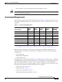
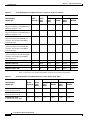
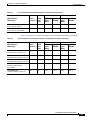
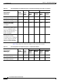
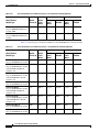
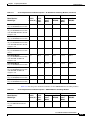
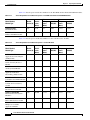
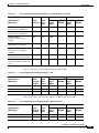
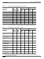
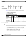
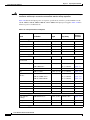
C H A P T E R
2
Preparing for Installation
Note
This publication describes the following Cisco 7600 series routers:
•
Cisco 7603 Router—CISCO7603
•
Cisco 7603-S Router—CISCO7603-S
•
Cisco 7604 Router—CISCO7604
•
Cisco 7606 Router—CISCO7606
•
Cisco 7606-S Router—CISCO7606-S
•
Cisco 7609 Router—CISCO7609
•
Cisco 7609-S Router—CISCO7609-S
•
Cisco 7613 Router—CISCO7613
Information on the Cisco 7609 Router (product number OSR-7609) is in the Cisco 7609 Router
Installation Guide, located at this URL:
http://www.cisco.com/univercd/cc/td/doc/product/core/cis7600/hardware/osrouter/index.htm
This chapter describes how to prepare your site for Cisco 7600 series router installation and contains
these sections:
•
Safety, page 2-1
•
WarningThis unit is intended for installation in restricted access areas. A restricted access area can
be accessed only through the use of a special tool, lock and key, or other means of security., page 2-2
•
Power Connection Guidelines, page 2-19
•
Site Planning Checklist, page 2-32
For detailed information about module cabling requirements, see Appendix B, “Connector and Cable
Specifications”
Safety
Warning
This equipment must be grounded. Never defeat the ground conductor or operate the equipment in the
absence of a suitably installed ground conductor. Contact the appropriate electrical inspection
authority or an electrician if you are uncertain that suitable grounding is available.
Cisco 7600 Series Router Installation Guide
OL-4503-24
2-1
Chapter 2
Preparing for Installation
Site Requirements
Warning
This unit is intended for installation in restricted access areas. A restricted access area can be
accessed only through the use of a special tool, lock and key, or other means of security.
Warning
Only trained and qualified personnel should be allowed to install, replace, or service this equipment.
Warning
Read the installation instructions before connecting the system to the power source.
Warning
This product requires short-circuit (overcurrent) protection, to be provided as part of the building
installation. Install only in accordance with national and local wiring regulations.
Site Requirements
This section provides site power requirements for the Cisco 7600 series routers. You should verify the
site power prior to installing the router. Power requirements vary for each router; ensure that you verify
the site power for the type of router you are installing.
For EMI recommendations, refer to the Site Preparation and Safety Guide.
Preventing Electrostatic Discharge Damage
Electrostatic discharge (ESD) damage, which can occur when electronic cards or components are
improperly handled, results in complete or intermittent failures. Port adapters and processor modules
consist of printed circuit boards that are fixed in metal carriers. Electromagnetic interference (EMI)
shielding and connectors are integral components of the carrier. Although the metal carrier helps to
protect the board from ESD, use a preventive antistatic strap during handling.
Following are guidelines for preventing ESD damage:
•
Always use an ESD wrist or ankle strap and ensure that it makes good skin contact.
•
Connect the equipment end of the strap to an unfinished chassis surface.
•
When installing a component, use any available ejector levers or captive installation screws
toproperly seat the bus connectors in the backplane or midplane. These devices prevent
accidentalremoval, provide proper grounding for the system, and help to ensure that bus connectors
areproperly seated.
•
When removing a component, use any available ejector levers or captive installation screws to
release the bus connectors from the backplane or midplane.
•
Handle carriers by available handles or edges only; avoid touching the printed circuit boards or
connectors.
•
Place a removed component board-side-up on an antistatic surface or in a static shielding container.
If you plan to return the component to the factory, immediately place it in a static shielding
container.
•
Avoid contact between the printed circuit boards and clothing. The wrist strap only protects
components from ESD voltages on the body; ESD voltages on clothing can still cause damage.
Cisco 7600 Series Router Installation Guide
2-2
OL-4503-24
Chapter 2
Preparing for Installation
Site Requirements
•
Caution
Never attempt to remove the printed circuit board from the metal carrier.
For safety, periodically check the resistance value of the antistatic strap. The measurement should be
between 1 and 10 megohm (Mohm).
Environmental Requirements
Insure adequate spacing between racks using the information in Table 2-1. Keep all of the vents clear of
obstructions, including dust and foreign conductive material, and away from the exhaust ports of other
equipment.
Table 2-1
Chassis Airfow Requirements
Chassis Model
Airflow
Intake
Airflow
Exhaust
Air Filter
Option
Minimum
Clearance
(walls)
Minimum
Horizontal
Separation
CISCO7603 (Figure 1-13)
Right side
Left side
No
6 in (15 cm)
12 in (30.5)
CISCO7603-S (Figure 1-14)
Right side
Left side
No
6 in (15 cm)
12 in (30.5)
Yes
6 in (15 cm)
12 in (30.5)
6 in (15 cm)
12 in (30.5)
1
CISCO7604 (Figure 1-15)
Right side
Left side
CISCO7606 (Figure 1-16)
Right side
Left side
No
CISCO7606-S (Figure 1-17)
Right side
Left side
No
6 in (15 cm)
12 in (30.5)
2
6 in (15 cm)
12 in (30.5)
CISCO7609 (Figure 1-18)
Front
Rear
Yes
CISCO7609-S (Figure 1-18)
Front
Rear
Yes2
6 in (15 cm)
12 in (30.5)
CISCO7613 (Figure 1-19)
Right side
Left side
No
6 in (15 cm)
12 in (30.5)
1. See Installing the Air Filter Assembly on a Cisco 7606 Router and the Cisco 7606-S Router (Optional), page 5-119.
2. See Installing the Air Filter Assembly on a Cisco 7606 Router and the Cisco 7606-S Router (Optional), page 5-119.
Heat dissipation is an important consideration for sizing the air-conditioning requirements for an
installation. The power and heat associated with a Cisco 7600 series router varies based upon these
considerations:
•
Power supply type
•
Module types and quantities
•
Average traffic levels
Unless otherwise noted, the information in Table 2-2 through Table 2-18 assumes worst-case conditions
(with GBICs and port adapters installed, if applicable), so typical numbers are approximately 30 percent
below the numbers listed here. See Table 2-19 for a sample calculation of a router configuration.
This section provides the power and heat numbers for the Cisco 7600 series chassis and modules. The
following power requirements and heat dissipation tables are provided:
•
Chassis and fan trays—Table 2-2
•
Supervisor engines—Table 2-3
•
Policy Feature Cards (PFCs)—Table 2-4
•
Distributed Forwarding Cards (DFCs)—Table 2-5
Cisco 7600 Series Router Installation Guide
OL-4503-24
2-3
Chapter 2
Preparing for Installation
Site Requirements
Note
Table 2-2
•
Switch fabric modules—Table 2-6
•
10-Gigabit Ethernet modules—Table 2-7
•
Gigabit Ethernet modules—Table 2-8
•
10/100/1000 Ethernet modules—Table 2-9
•
Fast Ethernet switching modules—Table 2-10
•
10/100 Ethernet switching modules—Table 2-11
•
10BASE Ethernet switching modules—Table 2-12
•
FlexWAN and Enhanced FlexWAN modules—Table 2-13
•
Service modules—Table 2-14
•
SPA Interface Processors (SIPs)—Table 2-15
•
Ethernet service cards—Table 2-16
•
Optical service modules (OSMs)—Table 2-17
•
Miscellaneous cards—Table 2-18
Module power is the output from the power supply (internal to the system). The AC-input power is the
input from the outlet to the power supply. The percentage difference between the two values is the
efficiency of the power supply.
Power Requirements and Heat Dissipation—Chassis and Fan Trays
AC
DC
Module
Module
Current (A) Power
(Watts)
AC-Input
Power
(Watts)
Heat Diss.
(BTU/HR)
DC-Input
Power
(Watts)
Heat Diss.
(BTU/HR)
FAN-MOD-3 fan tray
0.80
34.00
43.00
145.00
46.00
156.00
FAN-MOD-3HS fan tray
2.98
125.16
156.45
534.28
168.23
574.49
2.29
96
120
411
129
441
1.05
44
55
188
59
202
4.29
180
225
769
242
827
7.40
311
389
1327
418
1427
11.5
483
604
2062
649
2217
7.00
294.00
368.00
1255.00
395.00
1349.00
Model Number/
Module Type
Cisco 7603 chassis
Cisco 7604 chassis
FAN-MOD-4HS fan tray
Cisco 7606 chassis
FAN-MOD-6
Cisco 7606 chassis
FAN-MOD-6HS
Cisco 7606 chassis
FAN-MOD-6SHS
Cisco 7609 chassis
with tiered-speed redundant fans
Cisco 7609-S chassis
FAN-MOD-9SHS
Cisco 7600 Series Router Installation Guide
2-4
OL-4503-24
Chapter 2
Preparing for Installation
Site Requirements
Table 2-2
Power Requirements and Heat Dissipation—Chassis and Fan Trays (continued)
AC
Model Number/
Module Type
DC
Module
Module
Current (A) Power
(Watts)
AC-Input
Power
(Watts)
Heat Diss.
(BTU/HR)
DC-Input
Power
(Watts)
Heat Diss.
(BTU/HR)
7.10
372.75
1272.94
400.81
1368.75
Cisco 7613 chassis
WS-C6K-13SLOT-FAN2 fan tray
Note
298.20
The module power values are based on 42 VDC. Power is distributed to each slot in the chassis from the
power supply’s 42 VDC output. Each module has DC-to-DC power supplies that convert the 42 VDC
into +2.5 VDC, +3.3 VDC, and +5 VDC to power the module. The 42 VDC is independent of the power
supply’s input voltage, either 110 VAC or 220 VAC.
Table 2-3 lists the power and the heat numbers for the supervisor engines.
Table 2-3
Power Requirements and Heat Dissipation—Supervisor Engines
AC
DC
Model Number/
Module Type
Module
Module
Current (A) Power
(Watts)
AC-Input
Power
(Watts)
Heat Diss.
(BTU/HR)
DC-Input
Power
(Watts)
Heat Diss.
(BTU/HR)
WS-X6K-S2-MSFC2
Supervisor Engine 2 with PFC2 and
MSFC2 daughter cards
3.46
145.32
181.65
620.33
195.32
667.03
WS-X6K-S2U-MSFC2
Supervisor Engine 2 with PFC2 and
MSFC2 daughter cards—Has 512 MB
of DRAM
3.46
145.32
181.65
620.33
195.32
667.03
Cisco 7600 Series Router Installation Guide
OL-4503-24
2-5
Chapter 2
Preparing for Installation
Site Requirements
Table 2-3
Power Requirements and Heat Dissipation—Supervisor Engines (continued)
AC
DC
Model Number/
Module Type
Module
Module
Current (A) Power
(Watts)
AC-Input
Power
(Watts)
Heat Diss.
(BTU/HR)
DC-Input
Power
(Watts)
Heat Diss.
(BTU/HR)
WS-SUP32-10GE-3B
Supervisor Engine 32 with PFC3B and
MSFC2A daughter cards
4.19
175.98
219.98
751.21
236.53
807.76
WS-SUP32-GE-3B
Supervisor Engine 32 with PFC3B and
MSFC2A daughter cards
3.69
154.98
193.73
661.57
208.31
711.37
WS-SUP720
Supervisor Engine 720 with PFC3A
daughter card and integrated MSFC3
and switch fabric
7.50
315.0
393.75
1344.66
423.39
1445.87
WS-SUP720-3B
Supervisor Engine 720 with PFC3B
daughter card and integrated MSFC3
and switch fabric
6.72
282.24
350.80
1204.81
379.35
1295.5
7.82
WS-SUP720-3BXL
Supervisor Engine 720 with PFC3BXL
daughter card and integrated MSFC3
and switch fabric
328.44
410.55
1402.03
441.45
1507.56
RSP720-3C-GE
6.90
290
362.50
1237.93
389.78
1331.11
RSP720-3CXL-GE
8.10
340.20
425.25
1452.23
457.26
1561.54
RSP720-3C-10GE
8.80
370
462.50
1579.43
497.31
1698.31
RSP720-3CXL-10GE
10
420
525
1792.87
564.51
1927.82
Table 2-4 lists the power and the heat numbers for the Policy Feature Cards (PFCs).
Table 2-4
Power Requirements and Heat Dissipation—Policy Feature Cards (PFCs)
AC
DC
Model Number/
Module Type
Module
Module
Current (A) Power
(Watts)
AC-Input
Power
(Watts)
Heat Diss.
(BTU/HR)
DC-Input
Power
(Watts)
Heat Diss.
(BTU/HR)
WS-F6K-PFC3A
Policy Feature Card 3A
2.25
94.50
118.13
403.40
127.02
433.76
WS-F6K-PFC3B
Policy Feature Card 3B
1.47
61.74
77.18
263.55
82.98
283.39
WS-F6K-PFC3BXL
Policy Feature Card 3BXL
2.57
107.94
134.93
460.77
145.08
495.45
Cisco 7600 Series Router Installation Guide
2-6
OL-4503-24
Chapter 2
Preparing for Installation
Site Requirements
Table 2-4
Power Requirements and Heat Dissipation—Policy Feature Cards (PFCs)
AC
DC
Model Number/
Module Type
Module
Module
Current (A) Power
(Watts)
AC-Input
Power
(Watts)
Heat Diss.
(BTU/HR)
DC-Input
Power
(Watts)
Heat Diss.
(BTU/HR)
VS-F6K-PFC3C
Policy Feature Card 3C
1.90
79.80
99.75
340.65
107.26
366.29
VS-F6K-PFC3CXL
Policy Feature Card 3CXL
2.50
105.00
131.25
448.22
141.13
481.96
Table 2-5 lists the power and the heat numbers for the Distributed Forwarding Cards (DFCs).
Table 2-5
Power Requirements and Heat Dissipation—Distributed Forwarding Cards (DFCs)
AC
DC
Model Number/
Module Type
Module
Module
Current (A) Power
(Watts)
AC-Input
Power
(Watts)
Heat Diss.
(BTU/HR)
DC-Input
Power
(Watts)
Heat Diss.
(BTU/HR)
WS-F6K-DFC
Distributed Forwarding Card
2.10
88.20
110.25
376.50
118.55
404.84
WS-F6K-DFC3A
2.57
Distributed Forwarding Card 3A
107.94
134.93
460.77
145.08
495.45
WS-F6K-DFC3B
1.67
Distributed Forwarding Card 3B
70.14
87.68
299.41
94.27
321.95
WS-F6K-DFC3BXL
Distributed Forwarding
Card 3BXL
2.38
99.96
124.95
426.70
134.35
458.82
WS-F6700-CFC
Centralized Forwarding Card
0.75
31.5
39.38
134.47
42.34
144.59
Cisco 7600 Series Router Installation Guide
OL-4503-24
2-7
Chapter 2
Preparing for Installation
Site Requirements
Table 2-5
Power Requirements and Heat Dissipation—Distributed Forwarding Cards (DFCs) (continued)
AC
Model Number/
Module Type
Module
Module
Current (A) Power
(Watts)
DC
AC-Input
Power
(Watts)
Heat Diss.
(BTU/HR)
DC-Input
Power
(Watts)
Heat Diss.
(BTU/HR)
WS-F6700-DFC3A
3.00
Distributed Forwarding Card 3A
126
157.5
537.86
169.35
578.35
WS-F6700-DFC3B
2.7
Distributed Forwarding Card 3B
113.40
141.75
484.08
152.42
520.51
WS-F6700-DFC3BXL
Distributed Forwarding
Card 3BXL
138.60
173.25
591.65
186.29
636.18
1.65
WS-F6700-DFC3C
Distributed Forwarding Card 3C
for use on CEF720 modules.
Supported only with Supervisor
Engine 720 and Supervisor
Engine 720-10GE
69.30
86.63
295.82
93.15
318.09
2.35
98.70
123.38
421.33
132.66
453.04
WS-F6700-DFC3CXL
Distributed Forwarding
Card 3CXL for use on CEF720
modules. Supported only with
Supervisor Engine 720 and
Supervisor Engine 720-10GE.
3.3
Table 2-6 lists the power and the heat numbers for the switch fabric modules.
Table 2-6
Power Requirements and Heat Dissipation—Switch Fabric Modules
AC
DC
Model Number/
Module Type
Module
Module
Current (A) Power
(Watts)
AC-Input
Power
(Watts)
Heat Diss.
(BTU/HR)
DC-Input
Power
(Watts)
Heat Diss.
(BTU/HR)
WS-C6500-SFM
Switch Fabric Module
2.79
117.18
146.5
500.2
157.5
537.86
WS-X6500-SFM2
Switch Fabric Module 2
3.09
129.78
162.23
554
174.4
595.7
Cisco 7600 Series Router Installation Guide
2-8
OL-4503-24
Chapter 2
Preparing for Installation
Site Requirements
Table 2-7 lists the power and the heat numbers for the 10-Gigabit Ethernet modules.
Note
Table 2-7
For all WS-X67xx modules, the values shown are for the baseboard only. When the baseboard has a CFC
or DFC3 daughter card installed, you must add the daughter card power to the baseboard power to get
the total slot power. For all other modules that support a mandatory or optional daughter card, you must
add the daughter card power to the baseboard power to get the total slot power.
Power Requirements and Heat Dissipation—10-Gigabit Ethernet Modules
AC
DC
Model Number/
Module Type
Module
Module
Current (A) Power
(Watts)
AC-Input
Power
(Watts)
Heat Diss.
(BTU/HR)
DC-Input
Power
(Watts)
Heat Diss.
(BTU/HR)
WS-X6502-10GE
2-port 10-Gigabit Ethernet
module
3.30
138.60
173.25
591.65
186.29
636.18
WS-X6704-10GE
4-Port 10-Gigabit Ethernet
module
6.28
263.76
329.70
1125.93
354.52
1210.67
10.58
WS-X6708-10G-3C
8-Port 10-Gigabit Ethernet
module with WS-F6700-DFC3C
daughter card.
444.36
555.45
1896.86
600.49
2050.66
11.28
473.76
592.20
2022.36
640.22
2186.34
WS-X6708-10G-3CXL
8-Port 10-Gigabit Ethernet
module with
WS-F6700-DFC3CXL daughter
card.
Table 2-8 lists the power and the heat numbers for the Gigabit Ethernet modules.
Table 2-8
Power Requirements and Heat Dissipation—Gigabit Ethernet Modules
AC
DC
Model Number/
Module Type
Module
Module
Current (A) Power
(Watts)
AC-Input
Power
(Watts)
Heat Diss.
(BTU/HR)
DC-Input
Power
(Watts)
Heat Diss.
(BTU/HR)
WS-X6316-GE-TX
16-port 1000BASE-T Gigabit
Ethernet module
5.15
216.3
270.38
923.33
290.73
992.83
WS-X6408A-GBIC
8-port 1000BASE-X Gigabit
Ethernet module
2.00
84.00
105.00
358.58
112.90
385.56
WS-X6416-GBIC
16-port 1000BASE-X Gigabit
Ethernet module
2.81
118.02
147.53
503.8
158.63
541.72
Cisco 7600 Series Router Installation Guide
OL-4503-24
2-9
Chapter 2
Preparing for Installation
Site Requirements
Table 2-8
Power Requirements and Heat Dissipation—Gigabit Ethernet Modules (continued)
AC
DC
Model Number/
Module Type
Module
Module
Current (A) Power
(Watts)
AC-Input
Power
(Watts)
Heat Diss.
(BTU/HR)
DC-Input
Power
(Watts)
Heat Diss.
(BTU/HR)
WS-X6416-GE-MT
8-port 1000BASE-SX Gigabit
Ethernet module
2.50
105.00
131.25
448.22
141.13
481.96
WS-X6516-GBIC
16-port 1000BASE-X Gigabit
Ethernet module
3.40
142.80
178.50
609.58
191.94
655.46
WS-X6516A-GBIC
16-port 1000BASE-X Gigabit
Ethernet module
3.62
152.04
190.05
649.02
204.35
697.87
WS-X6724-SFP
24-Port 1000BASE-X Ethernet
module
2.23
99.66
117.08
399.81
125.89
429.90
WS-X6748-SFP
48-Port 1000BASE-X Ethernet
module
5.32
223.44
279.30
953.81
300.32
1025.60
WS-X6816-GBIC
16-Port1000BASE-X Gigabit
Ethernet module
3.84
161.28
201.60
688.46
216.77
740.28
Table 2-9 lists the power and the heat numbers for the 10/100/1000 Ethernet switching modules.
Table 2-9
Power Requirements and Heat Dissipation—10/100/1000 Ethernet Switching Modules
AC
DC
Model Number/
Module Type
Module
Module
Current (A) Power
(Watts)
AC-Input
Power
(Watts)
Heat Diss.
(BTU/HR)
DC-Input
Power
(Watts)
Heat Diss.
(BTU/HR)
WS-X6148-GE-TX
48-port 10/100/1000 Ethernet
module
2.47
104.0
130.0
443.0
139.0
476.0
WS-X6148V-GE-TX
48-port 10/100/1000 Ethernet
module with
WS-F6K-VPWR-GE PoE
daughter card
2.89
121.38
151.72
518.14
163.15
557.14
2.65
WS-X6148-GE-45AF
48-port 10/100/1000 Ethernet
module with WS-F6K-GE48-AF
PoE daughter card
111.30
139.13
475.11
149.60
510.87
105.0
131.25
448.22
141.13
481.96
WS-X6148A-GE-TX
48-port 10/100/1000 Ethernet
module
2.5
Cisco 7600 Series Router Installation Guide
2-10
OL-4503-24
Chapter 2
Preparing for Installation
Site Requirements
Table 2-9
Power Requirements and Heat Dissipation—10/100/1000 Ethernet Switching Modules (continued)
AC
Model Number/
Module Type
Module
Module
Current (A) Power
(Watts)
DC
AC-Input
Power
(Watts)
Heat Diss.
(BTU/HR)
DC-Input
Power
(Watts)
Heat Diss.
(BTU/HR)
2.68
WS-X6148A-GE-45AF
48-port 10/100/1000 Ethernet
module with WS-F6K-GE48-AF
PoE daughter card
112.56
140.70
480.49
151.29
516.66
WS-X6516-GE-TX
16-port 10/100/1000 Ethernet
module
3.45
144.90
181.13
618.54
194.76
665.10
WS-X6548-GE-TX
48-port 10/100/1000 Ethernet
module
2.98
125.16
156.45
534.28
168.23
574.49
WS-X6548V-GE-TX
10/100/1000 Ethernet module
with WS-F6K-VPWR-GE PoE
daughter card
3.40
142.80
178.50
609.58
191.94
655.46
3.16
WS-X6548-GE-45AF
48-port 10/100/1000 Ethernet
module with WS-F6K-GE48-AF
PoE daughter card
132.72
165.90
566.55
178.39
609.19
WS-X6748-GE-TX
10/100/1000 Ethernet module
294.00
367.50
1255.01
395.16
1349.48
7.00
Table 2-10 lists the power and the heat numbers for the Fast Ethernet switching modules.
Table 2-10
Power Requirements and Heat Dissipation—Fast Ethernet Switching Modules
AC
DC
Model Number/
Module Type
Module
Module
Current (A) Power
(Watts)
AC-Input
Power
(Watts)
Heat Diss.
(BTU/HR)
DC-Input
Power
(Watts)
Heat Diss.
(BTU/HR)
WS-X6148-FE-SFP
48-port 100BASE-X module
2.3
96.60
120.75
412.36
129.84
443.40
WS-X6224-100FX-MT
24-port 100BASE-FX Ethernet
module, MMF
1.90
79.8
99.75
340.65
107.26
366.3
WS-X6324-100FX-MM
24-port 100BASE-FX Ethernet
module, MMF
1.52
63.84
79.8
272.52
85.81
293.03
Cisco 7600 Series Router Installation Guide
OL-4503-24
2-11
Chapter 2
Preparing for Installation
Site Requirements
Table 2-10
Power Requirements and Heat Dissipation—Fast Ethernet Switching Modules
AC
DC
Model Number/
Module Type
Module
Module
Current (A) Power
(Watts)
AC-Input
Power
(Watts)
Heat Diss.
(BTU/HR)
DC-Input
Power
(Watts)
Heat Diss.
(BTU/HR)
WS-X6324-100FX-SM
24-port 100BASE-FX Ethernet
module, SMF
1.52
63.84
79.8
272.52
85.81
293.03
WS-X6524-100FX-MM
24-port 100BASE-FX Ethernet
module
1.90
79.8
99.75
340.65
107.3
366.3
Table 2-11 lists the power and the heat numbers for the 10/100 Ethernet switching modules.
Table 2-11
Power Requirements and Heat Dissipation—10/100 Ethernet Switching Modules
AC
Model Number/
Module Type
Module
Module
Current (A) Power
(Watts)
DC
AC-Input
Power
(Watts)
Heat Diss.
(BTU/HR)
DC-Input
Power
(Watts)
Heat Diss.
(BTU/HR)
WS-X6148-RJ-21
2.39
48-port 10/100 Ethernet module
100.38
125.48
428.5
134.92
460.75
2.39
WS-X6148-RJ21V
48-port 10/100 Ethernet module
with WS-F6K-VPWR PoE
daughter card
100.38
125.48
428.50
134.02
460.75
2.57
WS-X6148-21AF
48-port 10/100 Ethernet module
with WS-F6K-FE48-AF PoE
daughter card
107.94
134.93
460.77
145.08
495.45
WS-X6148-RJ-45
2.39
48-port 10/100 Ethernet module
100.38
125.48
428.50
134.92
460.75
2.39
WS-X6148-RJ45V
48-port 10/100 Ethernet module
with WS-F6K-VPWR PoE
daughter card
100.38
125.48
428.50
134.92
460.75
2.57
WS-X6148-45AF
48-port 10/100 Ethernet module
with WS-F6K-FE48-AF PoE
daughter card
107.94
134.93
460.77
145.08
495.45
WS-X6148A-RJ-45
1.00
48-port 10/100 Ethernet module
42.0
52.5
179.29
56.45
192.78
WS-X6148A-45AF
2.57
48-port 10/100 Ethernet module
107.94
134.93
460.77
145.08
495.45
Cisco 7600 Series Router Installation Guide
2-12
OL-4503-24
Chapter 2
Preparing for Installation
Site Requirements
Table 2-11
Power Requirements and Heat Dissipation—10/100 Ethernet Switching Modules (continued)
AC
Model Number/
Module Type
Module
Module
Current (A) Power
(Watts)
DC
AC-Input
Power
(Watts)
Heat Diss.
(BTU/HR)
DC-Input
Power
(Watts)
Heat Diss.
(BTU/HR)
WS-X6148X2-RJ-45
2.65
96-port 10/100 Ethernet module
111.30
139.13
475.11
149.60
510.87
3.07
WS-X6148X2-45AF
96-port 10/100 Ethernet module
with WS-F6K-FE48X2-AF PoE
daughter card
128.94
161.18
550.41
173.31
591.84
WS-X6196-RJ-21
2.74
96-port 10/100 Ethernet module
115.08
143.85
491.25
154.68
528.22
3.16
WS-X6196-21AF
96-port 10/100 Ethernet module
with WS-F6K-FE48X2-AF PoE
daughter card
132.72
165.90
566.55
178.39
609.19
WS-X6248A-TEL
2.69
48-port 10/100 Ethernet module
(telco)
113
141.23
482.28
151.85
518.58
2.39
WS-X6348-RJ21V
48-port 10/100 Ethernet module
with WS-F6K-VPWR PoE
daughter card
100.38
125.48
428.5
134.92
460.75
WS-X6348-RJ-45
2.39
48-port 10/100 Ethernet module
100.38
125.48
428.5
134.92
460.75
2.39
WS-X6348-RJ-45V
48-port 10/100 Ethernet module
with WS-F6K-VPWR PoE
daughter card
100.38
125.48
428.5
134.92
460.75
WS-X6548-RJ-21
2.90
48-port 10/100 Ethernet module
121.80
152.25
519.93
163.71
559.07
WS-X6548-RJ-45
2.90
48-port 10/100 Ethernet module
121.80
152.25
519.93
163.71
559.07
Table 2-12 lists the power and the heat numbers for the 10BASE Ethernet switching modules.
Table 2-12
Power Requirements and Heat Dissipation—10BASE Ethernet Switching Modules
AC
DC
Model Number/
Module Type
Module
Module
Current (A) Power
(Watts)
AC-Input
Power
(Watts)
Heat Diss.
(BTU/HR)
DC-Input
Power
(Watts)
Heat Diss.
(BTU/HR)
WS-X6024-10FL-MT
24-port 10BASE-FL Ethernet
module
1.52
79.8
272.52
85.81
293.0
63.84
Cisco 7600 Series Router Installation Guide
OL-4503-24
2-13
Chapter 2
Preparing for Installation
Site Requirements
Table 2-13 lists the power and the heat numbers for the FlexWAN and the enhanced FlexWAN modules.
Table 2-13
Power Requirements and Heat Dissipation—FlexWAN and Enhanced FlexWAN Modules
AC
DC
Model Number/
Module Type
Module
Module
Current (A) Power
(Watts)
AC-Input
Power
(Watts)
Heat Diss.
(BTU/HR)
DC-Input
Power
(Watts)
Heat Diss.
(BTU/HR)
WS-X6182-2PA
FlexWAN module
2.38
99.96
125
426.7
134.35
458.82
WS-X6582-2PA
Enhance FlexWAN module
2.50
105.00
131.25
448.22
141.13
481.96
Table 2-14 lists the power and the heat numbers for the available service modules.
Table 2-14
Power Requirements and Heat Dissipation—Service Modules
AC
DC
Model Number/
Module Type
Module
Module
Current (A) Power
(Watts)
AC-Input
Power
(Watts)
Heat Diss.
(BTU/HR)
DC-Input
Power
(Watts)
Heat Diss.
(BTU/HR)
ACE10-6500-K9
Applications Control Engine
(ACE) module
5.23
219.66
274.58
937.67
295.24
1008.25
WS-SVC-ADM-1-K9
Traffic Anomaly Detector
Module
4.00
168.00
210.00
717.15
225.81
771.13
WS-SVC-AGM-1-K9
Anomaly Guard Module
4.00
168.00
210.00
717.15
225.81
771.13
WS-SVC-AON-1-K9
Application-Oriented
Networking (AON) module
4.00
168.00
210.00
717.15
225.81
771.31
WS-SVC-CMM
6.00
Communications Media Module
252.0
315.0
1075.73
338.71
1156.69
WS-SVC-CSG-1
Content Services Gateway
module
3.00
126.0
157.5
537.86
169.35
578.35
WS-SVC-FWM-1-K9
Firewall Services Module
4.09
171.78
214.73
733.29
230.89
788.48
WS-SVC-IDSM2-K9
Intrusion Detection System
Module 2
2.50
105.00
131.25
448.22
141.13
481.96
WS-SVC-IPSEC-1
IPSec VPN Services module
1.89
79.38
99.23
338.85
106.69
364.36
WS-SVC-MWAM-1
Multiprocessor WAN
Application Module
3.57
149.94
187.43
640.06
201.53
688.23
Cisco 7600 Series Router Installation Guide
2-14
OL-4503-24
Chapter 2
Preparing for Installation
Site Requirements
Table 2-14
Power Requirements and Heat Dissipation—Service Modules (continued)
AC
DC
Model Number/
Module Type
Module
Module
Current (A) Power
(Watts)
AC-Input
Power
(Watts)
Heat Diss.
(BTU/HR)
DC-Input
Power
(Watts)
Heat Diss.
(BTU/HR)
WS-SVC-NAM-1
Network Analysis Module 1
2.89
121.38
151.73
518.14
163.15
557.14
WS-SVC-NAM-2
Network Analysis Module 2
3.47
145.74
182.18
622.13
195.89
668.95
WS-SVC-PSD-1
Persistent Storage Device
module
4.00
168.0
210.0
717.15
225.81
771.13
WS-SVC-WEBVPN-K9
WebVPN Services module
2.94
123.48
154.35
527.11
165.97
566.78
WS-SVC-WISM-1-K9
Wireless Services Module
(WiSM)
6.07
254.94
318.68
1088.25
342.66
1170.19
WS-SVC-WLAN-1-K9
Wireless LAN Services module
3.10
130.20
162.75
555.79
175.0
597.63
WS-X6066-SLB-S-K9
Content Switching module with
SSL
2.15
90.30
112.88
385.47
121.37
414.48
Table 2-15 lists the power and the heat numbers for SIP modules.
Table 2-15
Power Requirements and Heat Dissipation—SIPs
AC
DC
Model Number/
Module Type
Module
Module
Current (A) Power
@ 42 VDC (Watts)
AC-Input
Power
(Watts)
Heat Diss.
(BTU/HR)
DC-Input
Power
(Watts)
Heat Diss.
(BTU/HR)
7600-SIP-200
5.69
239
299
1021
322
1100
7600-SIP-400
5.95
250
312
1065
338
1154
7600-SIP-600
6.42
270
338
1153
363
1240
Table 2-16 lists the power and the heat numbers for Ethernet Services modules.
Table 2-16
Power Requirements and Heat Dissipation—Ethernet Services
AC
DC
Model Number/
Module Type
Module
Module
Current (A) Power
@ 42 VDC (Watts)
AC-Input
Power
(Watts)
Heat Diss.
(BTU/HR)
DC-Input
Power
(Watts)
Heat Diss.
(BTU/HR)
7600-ES20-10G3CXL
8.11
341
426
1454
458
1563
7600-ES20-10G3C
8.11
341
426
1454
458
1563
Cisco 7600 Series Router Installation Guide
OL-4503-24
2-15
Chapter 2
Preparing for Installation
Site Requirements
Table 2-16
Power Requirements and Heat Dissipation—Ethernet Services
AC
DC
Model Number/
Module Type
Module
Module
Current (A) Power
@ 42 VDC (Watts)
AC-Input
Power
(Watts)
Heat Diss.
(BTU/HR)
DC-Input
Power
(Watts)
Heat Diss.
(BTU/HR)
7600-ES20-GE3CXL
8.11
341
426
1454
458
1563
7600-ES20-GE3C
8.11
341
426
1454
458
1563
7600-ES+2TGCXL
7.06
297
371.25
1267.81
399.19
1363.24
7600-ES+2TG3C
6.38
268
335
1144.02
360.21
1230.13
7600-ES+4TGCXL
9.49
399
498.75
1703.23
536.29
1831.43
7600-ES+4TG3C
8.82
370
362
1236.23
497.31
1698.31
7600-ES+40G3C
9.3
391
488.75
1669.08
122.31
417.69
7600-ES+20G3CXL
7.25
305
381.25
1301.96
409.94
1399.96
7600-ES+20G3C
6.58
276
345
1178.17
370.96
1266.85
7600-ES+40G3CXL
9.97
419
523.75
1788.60
563.17
1923.23
Table 2-17 lists the power and the heat numbers for Optical Service modules (OSMs).
Table 2-17
Power Requirements and Heat Dissipation—OSMs
AC
DC
Model Number/
Module Type
Module
Module
Current (A) Power
@ 42 VDC (Watts)
AC-Input
Power
(Watts)
Heat Diss.
(BTU/HR)
DC-Input
Power
(Watts)
Heat Diss.
(BTU/HR)
OSM-2OC12-POS-MM, -SI,
-SL
OC-12 POS, 2-port
3.35
141
176
602
190
648
OSM-2OC12-POS-MM+, -SI+ 3.35
OC-12 POS, 2-port
141
176
816
190
648
OSM-4OC12-POS-MM, -SI,
-SL
OC-12 POS, 4-port
4.78
201
251
857
270
921
OSM-4OC12-POS-SI+
OC-12 POS, 4-port
4.54
191
239
816
257
877
OSM-4OC3-POS-SI
OC-3 POS, 4-port
2.42
102
128
437
138
4.70
OSM-4OC3-POS-SI+
OC-3 POS, 4-port
2.42
102
128
437
138
4.70
OSM-8OC3-POS-SI, -SL
OC-3 POS, 8-port
3.57
150
187
640
202
688
OSM-8OC3-POS-SI+, -SL+
OC-3 POS, 8-port
3.57
150
187
640
202
688
OSM-16OC3-POS-SI, -SL
OC-3 POS, 16-port
5.09
214
267
913
287
981
Cisco 7600 Series Router Installation Guide
2-16
OL-4503-24
Chapter 2
Preparing for Installation
Site Requirements
Table 2-17
Power Requirements and Heat Dissipation—OSMs
AC
DC
AC-Input
Power
(Watts)
Heat Diss.
(BTU/HR)
DC-Input
Power
(Watts)
Heat Diss.
(BTU/HR)
203
254
868
271
925
3.61
152
190
649
204
698
4.00
168
210
717
226
771
OSM-1OC48-POS-SS, -SI, -SL 4.26
OC-48 POS, 1-port
179
223
762
240
819
OSM-1OC48-POS-SS+, -SI+,
-SL+
OC-48 POS, 1-port
3.90
164
205
699
220
752
OSM-12CT3/DS0
Channelized T-3 to DS-0,
12-port
2.80
118
147
502
158
540
OSM-1CHOC12/T1-SI
Channelized OC-12/STM-4 to
DS-0, 1 port
2.80
118
147
502
158
540
OSM-1CHOC12/T3-SI
Channelized OC-12, 1-port
3.76
158
231
789
248
848
OSM-1CHOC48/T3-SS
Channelized OC-48, 1-port
5.76
242
197
672
212
723
OSM-2OC48/1DPT-SS, -SI,
-SL
OC-48 DPT1/POS, 2-ports
3.59
151
302
1031
325
1108
OSM-4GE-WAN-GBIC2
Gigabit Ethernet WAN Services
Module, 4-port
5.07
213
188
644
203
692
OSM-2+4GE-WAN+
Gigabit Ethernet WAN Services
Module, 2+4-port
3.76
158
267
911
287
979
Model Number/
Module Type
Module
Module
Current (A) Power
@ 42 VDC (Watts)
OSM-16OC3-POS-SI+
OC-3 POS, 16-port
4.83
OSM-2OC12-ATM-MM, -SI
OC-12 ATM, 2-port
OSM-2OC12-ATM-MM+,
-SI+
OC-12 ATM, 2-port
1. DPT = Dynamic Packet Transport
2. GBICs = Gigabit Interface Converters
Table 2-18 lists the power and the heat numbers for miscellaneous modules.
Cisco 7600 Series Router Installation Guide
OL-4503-24
2-17
Chapter 2
Preparing for Installation
Site Requirements
Table 2-18
Power Requirements and Heat Dissipation—Miscellaneous Modules
AC
DC
Model Number/
Module Type
Module
Module
Current (A) Power
@ 42 VDC (Watts)
AC-Input
Power
(Watts)
Heat Diss.
(BTU/HR)
DC-Input
Power
(Watts)
Heat Diss.
(BTU/HR)
WS-X6066-SLB-APC
Content Switching Module
3.0
157.5
537.9
169.35
578.35
126.0
Table 2-19 provides a sample calculation of power and heat dissipation for the following router
configuration:
•
Cisco 7603 Router chassis (including AC-input power supplies)
•
One WS-X6K-S2U-MSFC2 supervisor engine
•
Two 4-port OC-12 POS modules
Table 2-19 Sample Calculation of Router Configuration
Input Current
AC-Input DC-Output
Power
Power
Heat Diss. 90 VAC 120 VAC 180 VAC
(Watts) (Watts)
(BTU/HR) (Amps) (Amps) (Amps)
240 VAC
(Amps)
Cisco 7603 Router chassis
(with fans)
88
34
302
0.98
0.74
0.49
0.37
WS-X6K-S2U-MSFC2
182
145
620
2.02
1.57
1.01
0.76
OSM-4OC12-POS-MM
OC-12 module 4-port
502
402
1714
5.58
4.18
2.78
2.10
Total
751
565
2565
8.35
6.26
4.16
3.14
Model Number/
Module Type
Power Requirements
Warning
Read the installation instructions before connecting the system to the power source.
Follow these requirements when preparing your site for the router installation:
•
The redundant power option provides a second, identical power supply to ensure that power to the
chassis continues uninterrupted if one power supply fails or input power on one line fails.
•
In systems configured with the redundant power option, connect each of the two power supplies to
a separate input power source. If you fail to do this, your system might be susceptible to total power
failure due to a fault in the external wiring or a tripped circuit breaker.
•
To prevent a loss of input power, be sure that the total maximum load on each circuit supplying the
power supplies is within the current ratings of the wiring and breakers.
Cisco 7600 Series Router Installation Guide
2-18
OL-4503-24
Chapter 2
Preparing for Installation
Power Connection Guidelines
•
In some systems, you might use an uninterruptible power supply (UPS) to protect against power
failures at your site. Avoid UPS types that use ferroresonant technology. These UPS types can
become unstable with systems like the Cisco 7600 series router, which can have substantial current
draw fluctuations due to bursty data traffic patterns.
Use the information in Table 2-2 through Table 2-18 to estimate the power requirements and
heat dissipation of a Cisco 7600 series router based on a given configuration of the router. Table 2-19
provides a sample calculation. Determining power requirements might be useful for planning the power
distribution system needed to support the router.
Power Connection Guidelines
This section provides the guidelines for connecting the Cisco 7600 series router AC and DC power
supplies to the site power source.
AC-Powered Systems
Basic guidelines for AC-powered systems include the following:
•
Each chassis power supply should have its own dedicated branch circuit.
•
The circuit must be protected by a dedicated two-pole circuit breaker. For North America, the circuit
breaker should be rated as follows:
– 15A for the 950 W power supply
– 15A or 20A for the 1400 W power supply
– 20A for the 1900 W power supply
– 20A for the 2700 W power supply
– 20A for the 3000 W power supply
– 30A for the 4000 W power supply.
– 20A for the 6000 W power supply (one for each of two inputs)
For everywhere else, the circuit breaker should be sized according to the power supply input rating
and local or national code requirements.
•
The AC power receptacles used to plug in the chassis must be the grounding type. The grounding
conductors that connect to the receptacles should connect to protective earth ground at the service
equipment.
Warning
Never defeat the ground conductor or operate the equipment in the absence of a suitably installed
ground conductor. Contact the appropriate electrical inspection authority or an electrician if you are
uncertain that suitable grounding is available.
Warning
The plug-socket combination must be accessible at all times because it serves as the main
disconnecting device.
Cisco 7600 Series Router Installation Guide
OL-4503-24
2-19
Chapter 2
Preparing for Installation
Power Connection Guidelines
Warning
This product requires short-circuit (overcurrent) protection, to be provided as part of the building
installation. Install only in accordance with national and local wiring regulations.
Table 2-20 lists the AC-input power cord options, specifications, and Cisco product numbers for the
950 W, 1400 W, 1900 W, 3000 W, 4000 W, and the 6000 W AC-input power supplies. Table 2-20 also
references power cord illustrations.
Table 2-20 AC-Input Power Cord Options
Locale
Part Number
Length
Plug Rating
Power Cord
Reference
Illustration
950 W Power Supply (PWR-950-AC=)
North America
CAB-AC15A-90L-US(=)
8 feet (2.5m)
125VAC, 15A
Figure 2-1
Europe
CAB-AC10A-90L-EU(=)
8 feet (2.5m)
250VAC, 10A
Figure 2-2
United Kingdom
CAB-AC10A-90L-UK(=)
8 feet (2.5m)
250VAC, 10A
Figure 2-3
Italy
CAB-AC10A-90L-IT(=)
8 feet (2.5m)
250VAC, 10A
Figure 2-4
Australia
CAB-AC10A-90L-AU(=)
8 feet (2.5m)
250VAC, 10A
Figure 2-5
1400 W Power Supply (PWR-1400-AC=)
Argentina
CAB-7513ACR=
14 feet (4.3 m) 10 A, 250 VAC
Figure 2-6
Australia,
New Zealand
CAB-7513ACA=
14 feet (4.3 m) 15 A, 250 VAC
Figure 2-7
Continental Europe
CAB-7513ACE=
14 feet (4.3 m) 16 A, 250 VAC
Figure 2-8’
CAB-2500W-EU=
16 A, 250 VAC
Figure 2-9
International
CAB-AC-2500W-INT
14 feet (4.3 m) 16 A, 250 VAC
Figure 2-10
Italy
CAB-7513ACI=
14 feet (4.3 m) 16 A, 250 VAC
Figure 2-11
Japan, North
America
CAB-7513AC=
14 feet (4.3 m) 20 A, 125 VAC
Figure 2-12
CAB-AC-2500W-US1=
16 A, 250 VAC
Figure 2-19
CAB-AC-C6K-TWLK=
16 A, 250 VAC
Figure 2-13
South Africa
CAB-7513ACSA=
14 feet (4.3 m) 16 A, 250 VAC
Figure 2-14
Switzerland
CAB-ACS-16=
14 feet (4.3 m) 16 A, 250 VAC
Figure 2-15
Switzerland
CAB-ACS-10=
7 feet (2.3 m)
10 A, 250 VAC
Figure 2-22
United Kingdom
CAB-7513ACU=
14 feet (4.3 m) 13 A, 250 VAC
Figure 2-16
China
CAB-AC16A-CH
14 feet (4.3 m) 16 A, 250 VAC
Figure 2-23
1900 W Power Supply (PWR-1900-AC/6=)
North America
(locking)
CAB-GSR16-US(=)
14 feet (4.3m)
250VAC, 20A
Figure 2-17
Europe
CAB-GSR16-EU(=)
14 feet (4.3m)
250VAC, 16A
Figure 2-17
International
CAB-AC16A-90L-IN(=)
14 feet (4.3m)
250VAC, 16A
Figure 2-17
2700 W Power Supply (PWR-2700-AC)
Cisco 7600 Series Router Installation Guide
2-20
OL-4503-24
Chapter 2
Preparing for Installation
Power Connection Guidelines
Table 2-20 AC-Input Power Cord Options (continued)
Locale
Part Number
Length
Plug Rating
Power Cord
Reference
Illustration
North America
(locking)
CAB-GSR16-US(=)
14 feet (4.3m)
250VAC, 20A
Figure 2-17
Europe
CAB-GSR16-EU(=)
14 feet (4.3m)
250VAC, 16A
Figure 2-17
International
CAB-AC16A-90L-IN(=)
14 feet (4.3m)
250VAC, 16A
Figure 2-17
China
CAB-AC16A-CH=
14 feet (4.3 m) 16 A, 250 VAC
Figure 2-23
Continental Europe
CAB-AC-2500W-EU=
14 feet (4.3 m) 16 A, 250 VAC
Figure 2-18
International
CAB-AC-2500W-INT=
14 feet (4.3 m) 16 A, 250 VAC
Figure 2-10
Israel
CAB-AC-2500W-ISRL=
14 feet (4.3 m) 16 A, 250 VAC
Figure 2-24
Japan, North
America
(nonlocking plug)
200–240VAC
operation
CAB-AC-2500W-US1=
14 feet (4.3 m) 16 A, 250 VAC
Figure 2-19
Japan, North
America (locking
plug)
200–240VAC
operation
CAB-AC-C6K-TWLK=
14 feet (4.3 m) 16 A, 250 VAC
Figure 2-13
Japan, North
America
100–120VAC
operation1
CAB-7513AC=
14 feet (4.3 m) 20 A, 125 VAC
Figure 2-12
South Africa
CAB-7513ACSA=
14 feet (4.3 m) 16 A, 250 VAC
Figure 2-14
Switzerland
CAB-ACS-16=
14 feet (4.3 m) 16 A, 250 VAC
Figure 2-15
Australia,
New Zealand
CAB-AC-16A-AUS=
14 feet (4.3 m) 16A,250 VAC
Figure 2-25
Power Distribution
Unit (PDU(=)2
CAB-C19-CBN
14 feet (4.3 m) 16 A, 250 VAC
Figure 2-26
3000 W Power Supply (WS-CAC-3000W)
Continental Europe
CAB-AC-2500W-EU=
14 feet (4.3 m) 16 A, 250 VAC
Figure 2-18
International
CAB-AC-2500W-INT=
14 feet (4.3 m) 16 A, 250 VAC
Figure 2-10
Japan, North
America
(nonlocking plug)
200–240VAC
operation
CAB-AC-2500W-US1=
14 feet (4.3 m) 16 A, 250 VAC
Figure 2-19
Japan, North
America (locking
plug)
200–240VAC
operation
CAB-AC-C6K-TWLK=
14 feet (4.3 m) 16 A, 250 VAC
Figure 2-13
Cisco 7600 Series Router Installation Guide
OL-4503-24
2-21
Chapter 2
Preparing for Installation
Power Connection Guidelines
Table 2-20 AC-Input Power Cord Options (continued)
Plug Rating
Power Cord
Reference
Illustration
Locale
Part Number
Length
Japan, North
America
100–120VAC
operation3
CAB-7513AC=
14 feet (4.3 m) 20 A, 125 VAC
Figure 2-12
Switzerland
CAB-ACS-16=
14 feet (4.3 m) 16 A, 250 VAC
Figure 2-15
China
CAB-AC16A-CH=
14 feet (4.3 m) 16 A, 250 VAC
Figure 2-23
Australia,
New Zealand
CAB-AC-16A-AUS=
14 feet (4.3 m) 16A,250 VAC
Figure 2-25
North America
WS-CAC-4000W-US=
12 feet (3.6m)
250VAC, 30A
Figure 2-20
International
WS-CAC-4000W-INT=
12 feet (3.6m)
250VAC, 30A
Figure 2-21
4000 W Power Supply
6000 W Power Supply
People’s Republic of CAB-AC16A-CH=
China
14 feet (4.3 m) 16 A, 250 VAC
Figure 2-23
Continental Europe
CAB-AC-2500W-EU=
14 feet (4.3 m) 16 A, 250 VAC
Figure 2-18
International
CAB-AC-2500W-INT=
14 feet (4.3 m) 16 A, 250 VAC
Figure 2-10
Israel
CAB-AC-2500W-ISRL=
14 feet (4.3 m) 16 A, 250 VAC
Figure 2-24
Japan, North
America
(nonlocking plug)
200–240VAC
operation
CAB-AC-2500W-US1=
14 feet (4.3 m) 16 A, 250 VAC
Figure 2-19
Japan, North
America (locking
plug)
200–240VAC
operation
CAB-AC-C6K-TWLK=
14 feet (4.3 m) 16 A, 250 VAC
Figure 2-13
Japan, North
America
100–120 VAC 4
CAB-7513AC= 4
14 feet (4.3 m) 20 A, 125 VAC
Figure 2-12
Switzerland
CAB-ACS-16=
14 feet (4.3 m) 16 A, 250 VAC
Figure 2-15
Australia,
New Zealand
CAB-AC-16A-AUS=
14 feet (4.3 m) 16A,250 VAC
Figure 2-25
1. The 3000 W power supply operating on 110 VAC delivers 1400 W.
2. The PDU power cable is designed for users who power their switch from a PDU. The end of the cable that plugs into the Cisco
7600 series router chassis has a C19 connector; the other end of the cable that plugs into the PDU has a C20 connector.
3. The 3000 W power supply operating on 110 VAC delivers 1400 W.
4. The 6000 W power supply operating on two 110 VAC inputs delivers 2900 W. When operating with 100–120VAC, you must
use two AC power cords and the power supply output is limited to 2900 W.
Cisco 7600 Series Router Installation Guide
2-22
OL-4503-24
Chapter 2
Preparing for Installation
Power Connection Guidelines
AC Power Cord Illustrations
This section contains the AC power cord illustrations. Note that an AC power cord may be used with
several power supplies. See the power supply specifications tables for the correct AC power cord
illustrations for your power supply.
Figure 2-1
CAB-AC15A-90L-US(=)
Plug: NEMA 5-15
Cordset rating: 15 A, 125 V
Length: 8 ft 2 in. (2.5 m)
113344
Connector: IEC 60320 C15
Figure 2-2
CAB-AC10A-90L-EU(=)
Plug: CEE 7/7
Cordset rating: 10 A, 250 V
Length: 8 ft 2 in. (2.5 m)
113342
Connector: IEC 60320 C15
Cisco 7600 Series Router Installation Guide
OL-4503-24
2-23
Chapter 2
Preparing for Installation
Power Connection Guidelines
Figure 2-3
CAB-AC10A-90L-UK(=)
Cordset rating: 10 A, 250 V
Length: 8 ft 2 in. (2.5 m)
Plug: BS 1363
Connector: IEC 60320 C15
113345
13 A
fuse
Figure 2-4
CAB-AC10A-90L-IT(=)
Plug: CEI 23-16/7
Cordset rating: 10 A, 250 V
Length: 8 ft 2 in. (2.5 m)
113343
Connector: IEC 60320 C15
Figure 2-5
CAB-AC10A-90L-AU(=)
Plug: SAA AS 3112
Cordset rating: 10 A, 250 V
Length: 8 ft 2 in. (2.5 m)
113341
Connector: IEC 60320 C15
Cisco 7600 Series Router Installation Guide
2-24
OL-4503-24
Chapter 2
Preparing for Installation
Power Connection Guidelines
Figure 2-6
CAB-7513ACR=
Plug: IRAM 2073
Cordset rating: 10 A, 250 V
Length: 14 ft 0 in. (4.26 m)
113352
Connector: IEC 60320 C19
Figure 2-7
CAB-7513ACA=
Plug: SAA AS 3112
Cordset rating: 15 A, 250 V
Length: 14 ft 0 in. (4.26 m)
113353
Connector: IEC 60320 C19
Figure 2-8
CAB-7513ACE=
Plug: CEE 7/7
Cordset rating: 16 A, 250 V
Length: 14 ft 0 in. (4.26 m)
113354
Connector: IEC 60320 C19
Cisco 7600 Series Router Installation Guide
OL-4503-24
2-25
Chapter 2
Preparing for Installation
Power Connection Guidelines
Figure 2-9
CAB-2500W-EU=
Plug: CEE 7/7
Cordset rating: 16 A, 250 V
Length: 14 ft 0 in. (4.26 m)
113360
Connector: IEC 60320 C19
Figure 2-10 CAB-AC-2500W-INT=
Cordset rating: 16 A, 250 V
Length: 14 ft 0 in. (4.26 m)
Plug: IEC 309
113361
Connector: IEC 60320 C19
Figure 2-11 CAB-7513ACI=
Plug: CEI 23-16/7
Cordset rating: 16 A, 250 V
Length: 14 ft 0 in. (4.26 m)
113355
Connector: IEC 60320 C19
Cisco 7600 Series Router Installation Guide
2-26
OL-4503-24
Chapter 2
Preparing for Installation
Power Connection Guidelines
Figure 2-12 CAB-7513AC=
Plug: NEMA 5-20
Cordset rating: 20 A, 125 V
Length: 14 ft 0 in. (4.26 m)
113356
Connector: IEC 60320 C19
Figure 2-13 CAB-AC-C6K-TWLK=
Cordset rating: 16 A, 250 V
Length: 14 ft 0 in. (4.26 m)
Connector: IEC 60320 C19
113363
Plug: NEMA L6-20
Figure 2-14 CAB-7513ACSA=
Plug: IEC 884
Cordset rating: 16 A, 250 V
Length: 14 ft 0 in. (4.26 m)
113357
Connector: IEC 60320 C19
Cisco 7600 Series Router Installation Guide
OL-4503-24
2-27
Chapter 2
Preparing for Installation
Power Connection Guidelines
Figure 2-15 CAB-ACS-16=
Connector: IEC 60320 C19
113364
Plug: SEV 5934-2
Type 23
Cordset rating: 16 A, 250 V
Length: 8 ft 2 in. (2.5 m)
Figure 2-16 CAB-7513ACU=
Plug: BS 1363
113359
13A replaceable fuse
Cordset rating: 13 A, 250 V
Length: 14 ft 0 in. (4.26 m)
Connector: IEC 60320 C19
Figure 2-17 AC Power Cord Plugs and Appliance Coupler for the 1900 W Power Supply
North America (Non-locking)
(1900W power supply)
NEMA 6-20 plug (20A, 250V)
North America (Locking)
(1900W power supply)
NEMA L6-20 plug (20A, 250V)
68142
International
(1900W power supply)
EN 60309 (16A, 250V)
Europe
VIIG plug
CEE (7) VII (16A)
Appliance coupler
C19W coupler
Hot EN60320/C19 (20A)
Cisco 7600 Series Router Installation Guide
2-28
OL-4503-24
Chapter 2
Preparing for Installation
Power Connection Guidelines
Figure 2-18 CAB-AC-2500W-EU=
Plug: CEE 7/7
Cordset rating: 16 A, 250 V
Length: 14 ft 0 in. (4.26 m)
113360
Connector: IEC 60320 C19
Figure 2-19 CAB-AC-2500W-US1=
Plug: NEMA 6-20
Cordset rating: 16 A, 250 V
Length: 14 ft 0 in. (4.26 m)
113362
Connector: IEC 60320 C19
Cordset rating: 30 A, 250 V
Length: 12 ft 0 in. (3.65 m)
Plug: NEMA L6-30
Hardwired to
power
supply
113366
Figure 2-20 WS-CAC-4000W-US=
Cisco 7600 Series Router Installation Guide
OL-4503-24
2-29
Chapter 2
Preparing for Installation
Power Connection Guidelines
Figure 2-21 WS-CAC-4000W-INT=
Hardwired to
power
supply
113365
Cordset rating: 32 A, 250 V
Length: 12 ft 0 in. (3.65 m)
Plug: IEC 60309
Figure 2-22 CAB-ACS-10=
Plug: SEV 1011
Cordset rating: 10 A, 250 V
Length: 7 ft 0 in. (2.13 m)
113358
Connector: IEC 60320 C19
Figure 2-23 CAB-AC16A-CH=
Connector: IEC
60320-1 C19
126792
Plug: GB16C
Cordset rating: 16A, 250V
Length: 14 ft 0 in. (4.26 m)
Cisco 7600 Series Router Installation Guide
2-30
OL-4503-24
Chapter 2
Preparing for Installation
Power Connection Guidelines
Figure 2-24 CAB-AC-2500W-ISRL=
Plug: SI16S3
Cordset rating: 16 A, 250 V
Length: 14 ft 0 in. (4.26 m)
130113
Connector: IEC 60320 C19
Figure 2-25 CAB-AC-16A-AUS
Plug: AU20S3
Cordset rating: 16 A, 250 V
Length: 14 ft 0 in. (4.26 m)
140586
Connector: IEC 60320 C19
Connector:
IEC 60320 C20
Connector:
IEC 60320 C19
Cordset rating: 16 A, 250 V
Length: 9 ft 0 in. (2.7 m)
140587
Figure 2-26 CAB-C19-CBN
DC-Powered Systems
Basic guidelines for DC-powered systems include the following:
•
Each chassis power supply should have its own dedicated input power source. The source must
comply with the safety extra-low voltage (SELV) requirements in the UL 60950, CSA 60950, EN
60950, IEC 60950 standards.
•
The circuit must be protected by a dedicated two-pole circuit breaker. The circuit breaker should be
sized according to the power supply input rating and local or national code requirements.
Cisco 7600 Series Router Installation Guide
OL-4503-24
2-31
Chapter 2
Preparing for Installation
Site Planning Checklist
Caution
•
The circuit breaker is considered the disconnect device and should be easily accessible.
•
The system ground is the power supply and chassis ground.
Do not connect the DC-return wire to the system frame or to the system grounding equipment.
Site Planning Checklist
Table 2-21 lists the site planning activities that you should perform prior to installing the Cisco 7600
series router. Completing each activity helps ensure a successful router installation.
Table 2-21 Site Planning Checklist
Task No.
Planning Activity
1
Space evaluation:
Verified By
Time
Date
Space and layout
Floor covering
Impact and vibration
Lighting
Maintenance access
2
Environmental evaluation:
Ambient temperature
Humidity
Altitude
Atmospheric contamination
Airflow
3
Power evaluation:
Input power type
Power receptacles (15A/20A/30A))
Receptacle proximity to the equipment
Dedicated (separate) circuits for redundant
power supplies
UPS for power failures
DC systems: Proper gauge wire and lugs
4
Grounding evaluation:
Circuit breaker size
CO ground (AC- and DC-powered systems)
5
Cable and interface equipment evaluation:
Cable type
Connector type
Cable distance limitations
Interface equipment (transceivers)
6
EMI evaluation:
Distance limitations for signaling
Site wiring
RFI levels
Cisco 7600 Series Router Installation Guide
2-32
OL-4503-24