1
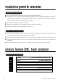
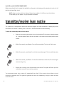
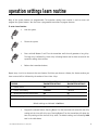
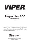
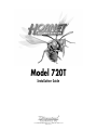
®
Model 720T
Installation Guide
®
© 2001 Directed Electronics, Inc. Vista, CA N720T 3-01
Rev. D 1.1
table of contents
What Is Included . . . . . . . . . . . . . . . . . . . . . . . . . . . . . . . . . . . . . . . . . . . . . . . . . . . . . . . . . . . . . . . . . . . 3
Installation Points to Remember. . . . . . . . . . . . . . . . . . . . . . . . . . . . . . . . . . . . . . . . . . . . . . . . . . . . . . . . . 4
Before Beginning the Installation . . . . . . . . . . . . . . . . . . . . . . . . . . . . . . . . . . . . . . . . . . . . . . . . . . . . . . 4
Locations for the Control Module/Siren . . . . . . . . . . . . . . . . . . . . . . . . . . . . . . . . . . . . . . . . . . . . . . . . . . . 4
Primary Harness (H1), 6-Pin Connector . . . . . . . . . . . . . . . . . . . . . . . . . . . . . . . . . . . . . . . . . . . . . . . . . . . . 4
Primary Harness (H1) Wiring Diagram . . . . . . . . . . . . . . . . . . . . . . . . . . . . . . . . . . . . . . . . . . . . . . . . . . . . 4
Primary Harness (H1) Wire Connection Guide . . . . . . . . . . . . . . . . . . . . . . . . . . . . . . . . . . . . . . . . . . . . . . . 5
Transmitter/Receiver Learn Routine. . . . . . . . . . . . . . . . . . . . . . . . . . . . . . . . . . . . . . . . . . . . . . . . . . . . . . . 6
Operating Settings Learn Routine . . . . . . . . . . . . . . . . . . . . . . . . . . . . . . . . . . . . . . . . . . . . . . . . . . . . . . . . 7
Feature Descriptions . . . . . . . . . . . . . . . . . . . . . . . . . . . . . . . . . . . . . . . . . . . . . . . . . . . . . . . . . . . . . . . . . 8
Shock Sensor Adjustments . . . . . . . . . . . . . . . . . . . . . . . . . . . . . . . . . . . . . . . . . . . . . . . . . . . . . . . . . . . . . 8
Troubleshooting . . . . . . . . . . . . . . . . . . . . . . . . . . . . . . . . . . . . . . . . . . . . . . . . . . . . . . . . . . . . . . . . . . . 10
Bitwriter™, Code Hopping™, DEI®, Doubleguard®, ESP™, FailSafe®, Ghost Switch™, Learn
Routine™, Nite-Lite®, Nuisance Prevention Circuitry®, NPC®, Revenger®, Silent Mode™, Soft Chirp®,
Stinger®, Valet®, Vehicle Recovery System®, VRS®, and Warn Away® are all Trademarks or
Registered Trademarks of Directed Electronics, Inc.
2
© 2001 Directed Electronics, Inc. Vista, CA
what is included
■
■
■
■
■
■
■
■
The control module (see diagram)
The siren and voice command module, on-board the control module
A Stinger Doubleguard dual-stage shock/impact sensor, on-board the control module
Two 2-button remote transmitters
H1 6-Pin Primary Harness
The status LED
A mounting bracket
A hardware pack
Control module with on-board
siren and shock sensor
© 2001 Directed Electronics, Inc. Vista, CA
3
installation points to remember
before beginning the installation
■ Do not disconnect the battery if the vehicle has an anti-theft-coded radio.
■ If equipped with an air bag, avoid disconnecting the battery if possible. Many airbag systems will display a
diagnostic code through their warning lights after they lose power. Disconnecting the battery requires this
code to be erased, which can require a trip to the dealer.
■ Check with the customer on status LED location.
■ Remove the domelight fuse. This prevents accidentally draining the battery.
■ Roll down a window to avoid being locked out of the car.
locations for the control module/siren
■ The control module with siren should be placed in the engine compartment, away from heat sources and areas
that must be accessed for routine maintenance of the vehicle.
■ The control module should be placed with the siren portion facing down to prevent water damage to the unit.
■ Route the wires away from the unit and make sure they are securely fastened away from the moving parts of
the engine.
■ Place the antenna as high as possible and as straight as possible for maximum operating range.
primary harness (H1), 6-pin connector
primary harness (H1) wiring diagram
H1/1
H1/2
H1/3
H1/4
H1/5
H1/6
4
______
______
______
______
______
______
ORANGE
WHITE
BLUE
BLUE/WHITE
BLACK
RED
(-) 500 mA GROUND-WHEN-ARMED OUTPUT
(-) LIGHT FLASH OUTPUT
(-) INSTANT TRIGGER INPUT
(-) 2V LED OUTPUT
(-) CHASSIS GROUND INPUT
(+) 12V CONSTANT POWER INPUT
© 2001 Directed Electronics, Inc. Vista, CA
primary harness (H1) wire connection guide
H1/1 ORANGE (-) GROUND-WHEN-ARMED OUTPUT
This wire supplies a (-) 500 mA ground as long as the system is armed. This output ceases as soon as the system
is disarmed. This output can be used to interrupt the starter circuit using an optional 8618 starter kill relay.
H1/2 WHITE (-) LIGHT FLASH OUTPUT
The unit supplies a 200 mA output that can be used to flash the parking lights of the vehicle. If the vehicle uses
a relay to drive the parking lights, this wire may be connected directly to the control wire for the factory relay.
In most cases, however, a relay will be required to drive the parking lights, as shown below.
H1/3 BLUE (-) INSTANT TRIGGER INPUT
This input can be used for hood and trunk pins or optional sensors.
H1/4 BLUE/WHITE 2V (-) LED OUTPUT
Connect this wire to the blue wire of the supplied LED. Connect the RED wire of the LED to a fused source of (+)
12V.
H1/5 BLACK (-) CHASSIS GROUND CONNECTION
Remove any paint and connect this wire to bare metal, preferably with a factory bolt rather than your own screw.
(Screws tend to either strip or loosen with time.) We recommend grounding all your components, including the
siren, to the same point in the vehicle.
© 2001 Directed Electronics, Inc. Vista, CA
5
H1/6 RED (+)12V CONSTANT POWER INPUT
Before connecting this wire, remove the supplied fuse. Connect to the battery positive terminal or to the (+) 12V
feed for the dome light circuit.
NOTE: Always use a fuse within 12 inches of the point you obtain (+) 12V. Do not use the 10A fuse
in the harness for this purpose. This fuse protects the module.
transmitter/receiver learn routine
This system uses a microprocessor-based learn routine to program and store transmitters in memory. Up to four
transmitters are retained in memory, even if the unit is disconnected from the vehicle battery.
To enter the transmitter/receiver learn routine:
1.
Power up the system by placing the fuse in the fuse holder. If the system is already powered
up, it must be powered down and back up before it will enter the transmitter/receiver learn
routine.
2.
Within five seconds, press Button I on the first transmitter. The siren will chirp once.
3.
Within five seconds, press Button I on the first transmitter again. The siren will chirp twice.
4.
Within five seconds, press Button I on the first transmitter a third time. The unit will generate one long chirp.
5.
Repeat steps 2 through 4 for all transmitters to be learned. The system will learn up to four
transmitters using the learn routine procedure.
The transmitter/receiver learn routine will automatically be exited if five seconds elapse without the unit
receiving a transmitter code. The system will generate one short chirp followed by a long chirp when the learn
routine is exited.
6
© 2001 Directed Electronics, Inc. Vista, CA
operation settings learn routine
Many of the system features are programmable. The operation settings learn routine is used to access and
program the system features. You must have a programmed transmitter to program features.
To enter Learn Routine:
1.
Arm the system.
2.
Disarm the system.
3.
Press and hold Buttons I and II on the transmitter until the unit generates a long chirp.
The long chirp is followed by a short chirp indicating feature one has been accessed in the
operation settings learn routine.
4.
Release the transmitter buttons.
Repeat steps 3 and 4 to advance to the next feature. Each time you advance a feature, the feature number you
have accessed will be indicated by the number of short siren chirps.
FEATURE
ONE CHIRP - PRESS
TRANSMITTER BUTTON I
TWO CHIRPS - PRESS
TRANSMITTER BUTTON II
1 - Current Sense
ON
OFF
2 - Current Sense Delay
5 Seconds
5 Minutes
3 - Audible Arm/Disarm Confirmation
ON
OFF
4 - Code-Hopping
ON
OFF
5 - Voice
ON
OFF
Default settings are indicated in bold text.
5.
Program the selected feature. Pressing Button I on the transmitter will select the one chirp
setting and the siren will chirp once. Pressing Button II on the transmitter will select the
two chirp setting and the siren will chirp twice. The default settings are indicated by bold
text in the table above.
© 2001 Directed Electronics, Inc. Vista, CA
7
After programming a feature, another feature can be selected by repeating steps 3 and 4. The Learn Routine will
be exited if you wait longer than five seconds between steps. The system will exit Learn Routine immediately if
you repeat steps 3 and 4 more times than there are features. When the operation settings learn routine is exited,
the unit will chirp once followed by a long chirp.
feature descriptions
1 - CURRENT SENSE ON/OFF: This feature is used to defeat the current sensor of the unit. If turned off, the
system cannot detect the doors opening, unless the blue wire has been connected to the door switch circuit.
2 - CURRENT SENSE DELAY 5 SECONDS/5 MINUTES: This feature selects the delay time before the current sensor
can trigger the unit. In some vehicles, electric fans and other circuits may stay on after the ignition is turned
off. Selecting the five minute delay will prevent those systems from triggering the current sensor.
3 - ARM/DISARM CHIRPS ON/OFF: This feature controls the chirps that confirm the arming and disarming of the
system.
4 - CODE-HOPPING™ ON/OFF: The system uses a mathematical formula called an algorithm to change its code
each time the transmitter and receiver communicate. This makes the group of bits, or “word,” from the transmitter very long. The longer the word is, the easier it is to block its transmission to the unit. Disabling the
Code-Hopping™ feature lets the receiver ignore the Code-Hopping part of the transmitter word. As a result, the
unit may have better range with Code-Hopping off.
5 - VOICE ON/OFF: The voice messages of the system can be disabled and replaced with chirps if the voice
feature is programmed off.
shock sensor adjustment
The system features a Doubleguard shock sensor built into the control unit. All adjustments to the sensor are
made using the transmitter.
To adjust the shock sensor Warn Away:
1.
8
Disarm the system.
© 2001 Directed Electronics, Inc. Vista, CA
2.
Within five seconds, press and hold Button II on the transmitter until the unit generates
a long chirp.
3.
Release Button II on the transmitter.
To test and adjust the current Warn Away setting:
Strike the vehicle to test the current setting. If the impact is detected, the unit will chirp three or four times.
If the current setting is acceptable, do nothing and the unit will exit shock sensor adjustment mode. If the
current setting is unacceptable, press Button I to decrease the sensitivity or Button II to increase the sensitivity. Each time Button II is pressed, the unit will emit two chirps and the sensitivity will be increased one level.
There are 16 possible settings. When the maximum or minimum setting is achieved, the siren will emit a long
chirp.
To adjust the shock sensor full trigger:
1.
Arm the system.
2.
Within five seconds, press and hold Button II on the transmitter until the unit generates
a long chirp.
3.
Release Button II on the transmitter.
To test and adjust the current full trigger setting:
Strike the vehicle to test the current setting. If the impact is detected, the unit will chirp three or four times.
If the current setting is acceptable, do nothing and the unit will exit shock sensor adjustment mode. If the
current setting is unacceptable, press Button I to decrease the sensitivity or Button II to increase the sensitivity. Each time Button I is pressed, the unit will emit one chirp and the sensitivity will be decreased one step.
Each time Button II is pressed, the unit will emit two chirps and the sensitivity will be increased one level. There
are 16 possible settings. When the maximum or minimum setting is achieved, the siren will emit a long chirp.
NOTE: If more than five seconds elapse without an adjustment, shock sensor adjustment mode will
be exited. Repeat steps 1 through 3 to make additional adjustments.
The siren will generate one long chirp followed by two short chirps when the shock sensor adjustment mode is
exited.
© 2001 Directed Electronics, Inc. Vista, CA
9
troubleshooting
■ The current sensor does not work.
Is it programmed off? Is it programmed for five minute delay? (Refer to the Operation Settings Learn Routine
section of this guide.)
The current sensor can sense the domelight circuit more effectively if the red (+) 12V input wire is connected
directly to the domelight positive circuit. This is not necessary in most cases, but will help when the domelight
circuit is extremely low current.
■ The shock sensor is not sensitive enough.
The mounting of the control unit is critical to shock sensor performance. If relocation of the control unit does
improve performance of the sensor, the angle of the unit and the bracket may be changed as shown below.
Remember, the siren must be protected against water damage and the more the angle is changed, the easier it
is for water to collect in the siren housing.
DRW-11
■ After programming, the remote does not arm and disarm the system.
Follow the instructions for transmitter/receiver learn routine carefully. (Refer to the Transmitter/Receiver Learn
Routine section of this guide.) The remote must be pressed three separate times in order for the system to learn
the transmitter code properly.
10
© 2001 Directed Electronics, Inc. Vista, CA