1
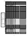
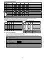
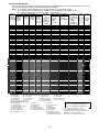
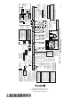
ADEMCO VISTA SERIES VISTA-20P / VISTA-20PSIA VISTA-15P / VISTA-15PSIA Security Systems Programming Guide K5305-1PRV5 10/04 Rev. A TO ENTER PROGRAMMING MODE (using an alpha keypad connected to the control): A. POWER UP, then press [✱] and [#] at the same time, within 50 seconds of powering up (this method must be used if ✱98 was used to exit program mode). OR B. Initially, key: Installer Code (4 + 1 + 1 + 2) plus 8 + 0 + 0. PROGRAMMING MODE COMMANDS Task Go to a Data Field Entering Data Review a Data Field Deleting an Entry Initialize Download ID Reset Factory Defaults Zone Programming Function Key Programming Zone Programming (Expert Mode) Output Device Mapping Output Programming Zone List Programming Alpha Programming Exit Program Mode with installer code lockout Exit Program Mode Command/Explanation Press [∗ ∗] + [Field Number], followed by the required entry. When the desired field number appears, simply make the required entry. When the last entry for a field is entered, the keypad beeps three times and automatically displays the next data field in sequence. If the number of digits that you need to enter in a data field is less than the maximum digits available (for example, the phone number fields *41, *42), enter the desired data, then press [∗ ] to end the entry. The next data field number is displayed. Press [#] + [Field Number]. Data will be displayed for that field number. No changes will be accepted in this mode. Press [∗ ∗] + [Field Number] + [∗ ∗]. (Applies only to fields ∗40 thru *46, *94, and pager fields) Press ∗96. Initializes download ID and subscriber account number. Press ∗97. Sets all data fields to original factory default values. Press ∗56. Zone characteristics, report codes, alpha descriptors, and serial numbers for 5800 RF transmitters. Press ∗57. Unlabeled keypad keys (known as ABCD keys) for special functions Press ∗58. Same options as *56 mode, but with fewer prompts. Intended for those familiar with this type of programming, otherwise *56 mode is recommended. Press ∗79. Assign module addresses and map individual relays/powerline carrier devices Press ∗80. 4229 or 4204 Relay modules, Powerline Carrier devices, or on-board triggers Press ∗81. Zone Lists for relay/powerline carrier activation, chime zones, pager zones, etc. Press ∗82. Zone alpha descriptors Press ∗98. Exits programming mode and prevents re-entry by: Installer Code + 8 + 0 + 0. To reenter programming mode, the system must be powered down, then powered up. Then use method A above. See field *88 for other *98 Program mode lockout options. Press ∗99. Exits programming mode and allows re-entry by: Installer Code + 8 + 0 + 0 or method A above. SPECIAL MESSAGES OC = OPEN CIRCUIT (no communication between Keypad and Control). EE or ENTRY ERROR = ERROR (invalid field number entered; re-enter valid field number). After powering up, AC, dI (disabled) or Busy Standby and NOT READY will be displayed after approximately 4 seconds. This will revert to a “Ready” message in approximately 1 minute, which allows PIRS, etc. to stabilize. You can bypass this delay by pressing [#] + [0]. If E4 or E8 appears, more zones than the expansion units can handle have been programmed. The display will clear after you correct the programming. TABLE OF DEVICE ADDRESSES This Device Uses Address RF Receiver 00 AUI 1 01 AUI 2 02 Long Range Radio 03 4286 Voice Module 04 Zone Expanders (4219/4229): module 1 (for zones 09 - 16) 07 module 2 (for zones 17 - 24) 08 module 3 (for zones 25 - 32) 09** module 4 zones 33 - 40 10** module 5 zones 41 - 48 11** Relay Modules (4204): module 1 12 module 2 13 module 3 14** module 4 15** Keypads: keypad 1 16 keypad 2 17 keypad 3 18 keypad 4 19 keypad 5 20 keypad 6 21 keypad 7 22 keypad 8 23 5800TM Module 28 Reports as †† 100 101 102 103 104 107 108 109 110 111 112 113 114 115 n/a n/a n/a n/a n/a n/a n/a n/a n/a Enabled By… *56 zone programming: input device type entry Automatic if AUI enable field *189 enabled for AUI 1 Automatic if AUI enable field *189 enabled for AUI 2 automatic if output to long range radio field *29 enabled automatic if phone module access code field *28 enabled *56 zone programming: input device type entry, then: automatic if zone no. 9-16 entered as AW type or relay assigned automatic if zone no. 17-24 entered as AW type or relay assigned automatic if zone no. 25-32 entered as AW type or relay assigned automatic if zone no. 33-40 entered as AW type or relay assigned automatic if zone no. 41-48 entered as AW type or relay assigned *79 output device programming: device address prompt: entered at device address prompt entered at device address prompt entered at device address prompt entered at device address prompt data field programming as listed below: always enabled, all sounds enabled. data field *190 data field *191 data field *192 data field *193 data field *194 data field *195 data field *196 automatic ** These module addresses apply to VISTA-20P only. †† Addressable devices are identified by “1” plus the device address when reporting. Enter report code for zone 91 to enable addressable device reporting (default = reports enabled). See field *199 for addressable device (ECP) 3-digit/2-digit identification keypad display options. –2– PROGRAMMING FORM Entries apply to the ADEMCO VISTA-15P/VISTA-15PSIA and ADEMCO VISTA-20P/VISTA-20PSIA controls, except entries shown in dashed boxes, which apply only to the VISTA-20P/VISTA-20PSIA (partition entries) and are not applicable to the VISTA-15P/VISTA-15PSIA. In addition, where noted, certain fields have special settings when used with the VISTA-20PSIA/VISTA-15PSIA (indicated by V20PSIA/V15PSIA with heavy borders and reverse type throughout for easy identification). Entry of a number other than one specified will give unpredictable results. Values shown in brackets are factory defaults. SIA Guidelines: Notes in certain fields give instructions for programming the VISTA-20P/VISTA-15P for False Alarm Reduction. ∗20 Installer Code [4112] | | ∗36 Entry Delay #2 | 4 digits, 0–9 ∗21 Quick Arm Enable ∗22 RF Jam Option ∗38 Confirmation Of Arming Ding Part. 1 Part. 2 [0,0] ∗39 Power Up In Previous State ∗24 RF House ID Code [00,00,00] | | | 00 = disable all wireless keypad usage Part. 1 Part. 2 01–31 = using 5827, 5827BD or 5804BD keypad ∗26 Chime By Zone Common DIALER PROGRAMMING (✱40 – ✱42) 0 = no; 1 = yes (list chime zones on zone list 3 using *81 Menu mode) Do not fill unused spaces. Enter 0–9; #+11 for '✱'; #+12 for '#'; #+13 for a 2second pause. If fewer than the maximum digits entered, exit the field by pressing [✶]. The next data field number is displayed. ∗40 PABX Access Code or [0] House Code [00] | 00 = disable; (Partition 1 only) 1st digit: enter 1–9; 2nd digit: enter # + 11 for "✱", or # + 12 for "#". UL: must be “00” for UL Commercial Burg. installations ∗29 Long Range Radio Output | | V20PSIA/V15PSIA: If “0” selected, “alarm sounding per zone” will be the same as the “number of reports in armed period” set in field *93 (1 if one report, 2 if 2 reports, unlimited for zones in zone list 7). [0] 0 = sound stops at timeout; 1 = no timeout UL: must be “1” for fire install. [1] | | | | 00 - 96 = 0 - 96 secs; 97 = 120 secs Part. 1 SIA Guidelines: minimum exit delay is 45 seconds | | | | | | | | | | | | | | | | | | | | | | | | | | | | | | ∗43 Partition 1 Primary Acct. No. | | | | | [FFFFFFFFFF] Enter 4 or 10 digits, as ∗44 Part. 1 Secondary Acct. No. (see field *43 for entries) | [FFFFFFFFFF] To clear, press *44*. | | | | | ∗45 Partition 2 Primary Acct. No. (see field *43 for entries) Part. 2 | | | / | | | | | [FFFFFFFFFF] To clear, press *45*. ∗46 Partition 2 Secondary Acct. No. (see field *43 for entries) | | | / | | | | | [FFFFFFFFFF] To clear, press *46*. ∗47 Phone System Select Common zones use part. 1 delay. | | chosen in *48 Report Format. See box above. To clear entries, press *43*. V20PSIA/V15PSIA: 45 - 96 = 45 - 96 secs; 97 = 120 secs NOTE: Entries less than 45 will result in a 45-second delay. [30,30] | NOTE: For fields *43 thru *46: Enter 0–9; #+11 for B; #+12 for C; #+13 for D; #+14 for E; #+15 for F. Enter [✱] as the fourth digit if a 3-digit account number (for 3+1 dialer reporting format) is used. Enter 0 as the first digit of a 4-digit account number for Nos. 0000-0999. Exit field by pressing ✱ if only 3 digits are used. E.g., For Acct. B234, enter: #+11 + 2 + 3 + 4 | | | / | | Enter up to 20 digits. To clear entries, press ✱41✱ or ✱42✱ respectively. | | | / 0 = none; 1 = 4 min; 2 = 8 min; 3 =12 min; 4 = 16 min; UL: For residential fire alarm installation, must be set for a minimum of 4 min (option 1); for UL Commercial Burglary installations, must be minimum 16 min (option 4) [60,60] | ∗42 Second Phone No. [0] 0 = unlimited sounding; 1 = one alarm sounding per zone ∗33 Alarm Sounder (Bell) Timeout | ∗41 Primary Phone No. 0 = disable; 1 = enable ∗32 Fire Alarm Sounder Timeout | V20PSIA/V15PSIA: If call waiting is used, enter call waiting disable digits as described above, and also set Call Waiting Disable option in field *91. [0] ∗31 Single Alarm Sounding Per Zone | Call Waiting Disable Enter up to 6 digits. To clear entries, press ✱40✱. If call waiting is used, enter call waiting disable digits “∗ (#+11) 70” plus “# + 13” (pause). NOTES: 1. The call waiting disable feature cannot be used on a PABX line. 2. Using Call Waiting Disable on a non-call waiting line will prevent successful communication to the central station. 0 = A; 1 = B; 2 = C; 3 = D; 4 = E; 5 = F; 6 = G; 7 = H; 8 = I; 9 = J; #10 = K; #11 = L; #12 = M; #13 = N; #14 = O; #15 = P UL: not for fire or UL installations ∗28 Access Code For Phone Module [1] 0 = no, always power up disarmed; 1 = yes, power up in previous state UL: must be “1” SIA Guidelines: must be “1” [0] ∗27 Powerline Carrier Device (X–10) ∗35 Entry Delay #1 Part. 1 Part. 2 0 = no; 1 = yes (wired keypads and RF) Part. 1 Part. 2 2 = yes, RF only UL: must be “1” for UL Commercial Burglar Alarm inst. [0,0] 0 = no quick bypass UL: must be “0” 1 = allow quick bypass (code + [6] + [#] ) UL: see inst. instr. for requirements. [1,1] V20PSIA/V15PSIA: feature always enabled; field does not exist [0] 0 = no RF Jam detection; 1 = send RF Jam report UL: must be 1 if wireless devices are used | Part. 2 0 = no; 1 = yes (SIA Guidelines: must be enabled) Part. 1 Part.2 ∗23 Quick (Forced) Bypass | Part. 1 ∗37 Audible Exit Warning [0,0] 0 = no; 1 = yes ∗34 Exit Delay [30,30] See *35 Entry Delay 1 for entries. Common zones use same delay as partition 1. Part. 1 Part. 2 00 - 96 = 0 - 96 seconds; 97 = 120 secs; 98 = 180 secs; 99 = 240 secs SIA Guidelines: minimum entry delay is 30 seconds [1] If Cent. Sta. is not on a WATS line: 0=Pulse Dial; 1=Tone Dial; if Cent. Sta. is on a WATS line: 2 = Pulse Dial ; 3 = Tone Dial | ∗48 Report Format V20PSIA/V15PSIA: 30-96 = 30 - 96 secs; 97 = 120 secs; 98 = 180 secs; 99 = 240 secs NOTE: Entries less than 30 will result in a 30-second delay. For UL Residential Burglary Alarm installations, must be set for a maximum of 30 seconds; entry delay plus dial delay should not exceed 1 min. For UL Commercial Burglar Alarm, total entry delay may not exceed 45 seconds. –3– [77] 0 = 3+1, 4+1 ADEMCO L/S STANDARD primary secondary 1 = 3+1, 4+1 RADIONICS STANDARD 2 = 4+2 ADEMCO L/S STANDARD 3 = 4+2 RADIONICS STANDARD 5 = 10-digit ADEMCO CONTACT ID® REPORTING 6 = 4+2 ADEMCO EXPRESS 7 = 4-digit ADEMCO CONTACT ID® REPORTING 8 = 3+1, 4+1 ADEMCO L/S EXPANDED 9 = 3+1, 4+1 RADIONICS EXPANDED ∗49 Split/Dual Reporting ∗66 Arm Away/Stay Rpt Code [0] 0 = Standard/backup reporting only (all to primary) Primary Phone No. 2nd Phone No. 1 = Alarms, Restore, Cancel Others 2 = All except Open/Close, Test Open/Close, Test 3 = Alarms, Restore, Cancel All 4 = All except Open/Close, Test All 5 = All All ∗50 Burglary Dialer Delay [0,0,0,0,0,0] Away Stay Part. 1 ∗68 Cancel Report Code [2,0] ∗53 SESCOA/Radionics Select ∗69 Recent Closing Report Code 0 = Radionics (0-9, B-F); enter “0” for all non-SESCOA formats 1 = SESCOA (0-9 only reporting) [0] Select delay from 0 to 225 secs, in 15-sec increments. 0 = no delay (both signals sent); 1 = 15 secs; 2 = 30 secs, etc. UL: Grade AA must be “0;” Grade A must be “15” max ∗55 Dynamic Signaling Priority [00] | [11] | V20PSIA/V15PSIA: Always enabled. Field does not apply to other controls. RESTORE REPORT CODES (✱70 – ✱76) ∗70 Alarm Restore Rpt Code [0] ∗71 Trouble Restore Rpt Code [00] | ∗72 Bypass Restore Rpt Code [00] | ∗73 AC Restore Rpt Code [00] | ∗74 Low Bat Restore Rpt Code [00] | ∗75 RF Trans. Lo Bat Rst Rpt Code [00] | [00] | UL: must be enabled if wireless devices are used ∗76 Test Restore Rpt Code [0] 0 = Primary Dialer first; 1 = Long Range Radio first. For UL Commercial Burglary installations that use a DACT and LRR, this field must be “0”. OUTPUT AND SYSTEM SETUP (✱77 – ✱93) ∗77 Daylight Savings Time ∗56, ∗57, ∗58 Menu Modes TO PROGRAM SYSTEM STATUS, & RESTORE REPORT CODES (∗ ∗59 thru ∗68, *70 thru ∗76, and ∗89): For 3+1 or 4+1 Standard Format: Enter a code in the first box: 1–9, #+10 for 0, #+11 for B, #+12 for C, #+13 for D, #+14 for E, #+15 for F. A 0 (not #+10) in the first box will disable a report. A 0 (not #+10) in the second box will result in automatic advance to the next field. For Expanded or 4+2 Format: Enter codes in both boxes (1st and 2nd digits) for 1–9, 0, or B–F, as described above. A 0 (not #+10) in the second box will eliminate the expanded message for that report. A 0 (not #+10) in both boxes will disable the report. For Ademco Contact ID® Reporting: Enter any digit (other than 0) in the first box, to enable zone to report (entries in the second boxes are ignored). A 0 (not #+10) in the first box disables the report. UL: see installation instructions for requirements [4][10] | Start/End Month These are Menu Mode commands, not data fields, for Zone Programming, Function Key Programming, and Expert Mode Zone Programming respectively. See page 2 and respective sections later in this document. 0 = Disabled 1-12 = January-September (1 = Jan, 2 = Feb, etc) #+10 = October; #+11 = November; #+12 = December ∗78 Daylight Savings Time [1][5] | Start/End Weekend 0 = disabled; 1 = first; 2 = second; 3 = third; 4 = fourth; 5 = last; 6 = next to last; 7 = third to last ∗79, *80, *81, *82 Menu Modes These are Menu Mode commands, not data fields, for Output Device Mapping, Output Programming, Zone List Programming, and Alpha Programming respectively. See page 2 and their respective sections in the Installation and Setup Guide for procedures. ∗84 Auto Stay Arm [3] 0 = no; 1 = partition 1 only; 2 = partition 2 only; 3 = both partitions SYSTEM STATUS REPORT CODES (✱59–✱ 68) ∗59 Exit Error Alarm Report Code [0] ∗85 Cross Zone Timer ∗60 Trouble Report Code [00] | ∗61 Bypass Report Code [00] | ∗62 AC Loss Report Code [00] | ∗63 Low Bat Report Code [00] | ∗64 Test Report Code [00] | [0] This option not for use in UL installations. (assign cross zones on zone list 4, using *81 Menu mode) 0 = 15 seconds 6 = 2-1/2 min #+12 = 8 min 1 = 30 seconds 7 = 3 min #+13 = 10 min 2 = 45 seconds 8 = 4 min #+14 = 12 min 3 = 60 seconds 9 = 5 min #+15 = 15 min 4 = 90 seconds #+10 = 6 min 5 = 2 minutes #+11 = 7 min V20PSIA/V15PSIA: [1] Always enabled. ∗86 Cancel Verify Keypad Display [1] 0 = no “alarm canceled” display 1 = display “Alarm Canceled” when system is disarmed after an alarm has occurred. (To clear the “ALARM CANCELED” display, the user must enter the security code + OFF again.) Use Scheduling mode to set periodic test reports, or use the following key commands: installer code +[#] + [0] + 0 = test report sent every 24 hours installer code +[#] + [0] + 1 = test report sent once per week installer code +[#] + [0] + 2 = test report sent every 28 day Each mode sets schedule 32 (VISTA-20P) or schedule 08 (VISTA-15P) to the stated repeat option; first test report sent 12 hours after command. ∗87 Misc. Fault Delay Time [0,0,0] Part. 1 | V20PSIA/V15PSIA: [10] Report enabled. [0] ∗54 Dynamic Signaling Delay [00] UL: must be enabled if wireless devices are used V20PSIA/V15PSIA: Delay Time: 1 = 15 seconds; 2 = 30 seconds; 3 = 45 seconds Delay Disable: 0 = use delay set in entry 1 1 = dial delay disabled for zones listed in zone list 6 (use zone list 6 to enter those zones that require dial delay to be disabled; these zones ignore the setting in entry 1) UL: Dial delay plus entry delay must not exceed one minute; use zone list 6 to disable dial delay from appropriate zones, if necessary. ∗65 Open Report Code Away Stay Common ∗67 RF Trans. Low Bat Report Code Delay Time: Delay Time V20PSIA/V15PSIA 0 = no delay UL: must be “0” Delay Disable 1 = 15 seconds; 2 = 30 seconds; 3 = 45 seconds SIA Guidelines: delay must be minimum of 30 seconds See above for entries. Away Stay Part. 2 Part. 2 Common –4– [0] (used with Configurable Zone Types “digit 6”) 0 = 15 seconds 6 = 2-1/2 min #+12 = 8 min 1 = 30 seconds 7 = 3 min #+13 = 10 min 2 = 45 seconds 8 = 4 min #+14 = 12 min 3 = 60 seconds 9 = 5 min #+15 = 15 min 4 = 90 seconds #+10 = 6 min 5 = 2 minutes #+11 = 7 min UL: may only be used on non-burglar alarm/ non-fire alarm zones when used in fire and/or UL burglar alarm installation ∗88 Program Mode Lockout Options ∗96, ∗97 Initialize/Reset Defaults [0] 0 = standard *98 installer code lockout (reentry only by [∗] + [#] within 50 seconds after power up) 1 = lockout [∗] + [#] reentry after *98 exit (reenter via installer code or downloader only) 2 = not used 3 = lockout local programming after *98 exit (reenter by downloader only) ∗89 Event Log Full Report Code [00] | This is a command, not a data field. See page 2. ∗98, *99 Exit Commands This is a command, not a data field. See page 2. PAGER OPTIONS (✱160- ✱172) ∗160 Pager 1 Phone No. | See box above field *59 for report code entries. | ∗90 Event Log Enables [3] NOTE: System messages are logged when any non-zero entry is made. 0 = None; 1 = Alarm/Alarm Restore 2 = Trouble/Trouble Restore; 4 = Bypass/Bypass Restore; 8 = Open/Close. Example: To select “Alarm/Alarm Restore”, and “Open/Close”, enter 9 (1 + 8); To select all, enter #15. ∗91 Option Selection [8, 0] | | ∗92 Phone Line Monitor Enable ∗93 Reports In Armed Period | | | | | | | | | | | | | | | | | | | | | | | | | | | | | | | | | | | | | | | | | | | | | | | | | | | | | | | | | | | | Enter the optional prefix characters, up to 16 digits. 0–9; #+11 = '✱'; #+12 = '#'; #+13 = 2-second pause. ∗165 Pager 2 Report Options [0,0,0] Part. 1 Part. 2 common See field *162 for reporting options. Select for each partition (use zone list 10 if using options 12 or 13). ∗166 Pager 3 Phone No. | | | Enter up to 20 digits. 0–9; #+11 = 'Q'; #+12 = '#'; #+13 = 2-sec pause Restrict V20PSIA/V15PSIA Report Pairs Unlimited Reports Enable | | | | | | | | | | | | | | | | | | Enter up to 20 digits. 0–9; #+11 = '✱'; #+12 = '#'; #+13 = 2-sec pause ∗167 Pager 3 Characters | | | | | | | | | | | | | | | Enter the optional prefix characters, up to 16 digits. 0–9; #+11 = '✱'; #+12 = '#'; #+13 = 2-second pause. ∗168 Pager 3 Report Options 0,0,0] Part. 1 Part. 2 common See field *162 for reporting options. Select for each partition (use zone list 11 if using options 12 or 13). ∗169 Pager 4 Phone No. DOWNLOAD INFORMATION (✱94, ✱95) ∗94 Download Phone No. | | ∗164 Pager 2 Characters V20PSIA/V15PSIA: Restrict Report Pairs: 1 = 1 report pair; 2 = 2 report pairs Unlimited Reports Enable: 0 = restrict reports to the setting in entry 1 1 = unlimited reports for zones listed in zone list 7; (use zone list 7 to enter those zones that require unlimited reporting; these zones ignore the setting in entry 1) | | Part. 1 Part. 2 common For each partition, select from the following options: 0 = no reports sent 1 = Opens/closes all users 4 = All alarms and troubles 5 = All alarms / troubles, and opens/closes for all users 12 = Alarms / troubles for zones entered in zone list 9 13 = Alarms / troubles for zones entered in zone list 9, and opens/closes for all users | [0,0] Restrict Report Pairs: 0 = Unlimited Reports 1 = 1 report pair 2 = 2 report pairs SIA Guidelines: Must be set for option 1 or 2. | | ∗163 Pager 2 Phone No. [1,0] Per Zone (Swinger Suppression) | | ∗162 Pager 1 Report Options Call Wait Disable UL: see Inst. Instructions for requirements 1 2 NOTE: Output Device must either be programmed to be STOPPED in field ✱80 or STOPPED by Code + # + 8 + output number. Entry 1:: 0 = disabled, 1-15 = 1 min - 15 min (#+10 = 10 min; #+11 = 11 min; #+12 = 12 min; #+13 = 13 min; #+14 = 14 min; #+15 = 15 min) Entry 2: 0 = Keypad display when line is faulted 1 = Keypad display plus keypad trouble sound 2 = Same as “1”, plus programmed output device STARTS. If either partition is armed, external sounder activates also. | | Enter the optional prefix characters, up to 16 digits. 0–9; #+11 = '✱'; #+12 = '#'; #+13 = 2-second pause. V20PSIA/V15PSIA V20PSIA/V15PSIA: Options: Same as listed above. Call Waiting Disable: 0 = call waiting not used 1 = call waiting disable digits (*70) entered in field *40; (when selected, the system dials the entry in field *40 only on alternate dial attempts; this allows proper dialing in the event call waiting service is later canceled by the user). | | ∗161 Pager 1 Characters 8 = Exit Delay Restart/Reset UL: must be disabled #+12 = AAV and Exit Delay Restart/Reset SIA Guidelines: Exit Delay should be enabled. | | [0,0,0] Options: 0 = None Options 4 = AAV UL: must use ADEMCO UVCM module | | Enter up to 20 digits. 0–9; #+11 = '✱'; #+12 = '#'; #+13 = 2-sec pause | | | | | | | | | | | | | | | | | | | Enter up to 20 digits. 0–9; #+11 = '✱'; #+12 = '#'; #+13 = 2-sec pause | | | | Enter up to 20 digits, 0–9; #+11 for '✱'; #+12 for '#'; #+13 for a 2second pause. Do not fill unused spaces. If fewer than 20 digits, exit field by pressing ✱. To clear entries from field, press ✱94✱. UL: downloading may be performed only if a technician is at the site. ∗95 Ring Count For Downloading NOTE: Do not enter “0” if using 4285/4286 Phone Module. 0 = Disable Station Initiated Download; 1–14 = number of rings (1–9, # +10 =10, # +11 =11, # +12 =12, # +13 =13, # +14 =14); 15 = answering machine defeat (# +15 =15). [15] ∗170 Pager 4 Characters | | | | | | | | | | | | | | | Enter the optional prefix characters, up to 16 digits. 0–9; #+11 = '✱'; #+12 = '#'; #+13 = 2-second pause. ∗171 Pager 4 Report Options [0,0,0] Part. 1 Part. 2 common See field *162 for reporting options. Select for each partition (use zone list 12 if using options 12 or 13). ∗172 Pager Delay Option For Alarms 0 = none; 1 = 1 minute; 2 = 2 minutes; 3 = 3 minutes This delay is for ALL pagers in the system. –5– [3] MISCELLANEOUS SYSTEM FIELDS (*174-*181) KEYPAD OPTIONS *190-*196 ∗174 Clean Me Reporting Options NOTES: 1. Options for keypad address 16 are set by the factory and cannot be changed.) 2. Each keypad must be assigned a unique address. Keypads programmed with the same address will give unpredictable results. [0] (for ESL smoke detectors) 0 = disable; 1 = Clean Me signal reports; NOTE: If Clean Me is enabled, you must enter “3” in field ✱56 programming for zone 1 response time. ∗177 Device Duration 1, 2 ∗190 Keypad 2 Device Address 17 [0] [0] (used in *80 Menu mode-Device Actions 5/6) 1 0 = 15 seconds 6 = 2-1/2 min #+11 = 7 min 1 = 30 seconds 7 = 3 min #+12 = 8 min 2 = 45 seconds 8 = 4 min #+13 = 10 min 3 = 60 seconds 9 = 5 min #+14 = 12 min 4 = 90 seconds #+10 = 6 min #+15 = 15 min 5 = 2 minutes ∗181 50/60 Hertz AC Operation 2 ∗191 Keypad 3 Device Address 18 [0] See field ∗190 for entries. 0 = 60 Hz; 1 = 50 Hz ∗192 Keypad 4 Device Address 19 CONFIGURABLE ZONE TYPE OPTIONS (*182-*185) See field ∗190 for entries. (see Configurable Zone Type Worksheet on page 7) ∗193 Keypad 5 Device Address 20 ∗182 Configurable Zone Type 90 1 2 3 4 5 6 See field ∗190 for entries. 7 8 9 10 Enter the appropriate value for each entry, 1-10, based on the charts provided on the next page. Each entry is the sum of the values of its selected options (0-9, #+10=10, #+11=11, #+12=12, #+13=13, #+14=14, #+15=15). UL: Do not configure zones as a fire alarm or UL burglar alarm zone. ∗195 Keypad 7 Device Address 22 See field ∗190 for entries. ∗196 Keypad 8 Device Address 23 IMPORTANT: Use existing Contact ID® codes, if appropriate, or define unique codes in CID code range 750-789. See important note in installation instructions. See field ∗190 for entries. 90 ALARM ID: XXX TROUBLE ID: XXX 4 5 6 ∗198 Display Partition Number 7 8 9 Sound [0] [0] Partition/ Enable Sound [0] [0] Partition/ Enable Sound [0] [0] Partition/ Enable Sound [0] [0] Partition/ Enable Sound [0] [0] Partition/ Enable Sound [0] [0] (VISTA-20P; for Alpha Display Keypads) 0 = no; 1 = yes (partition no. appears on Alpha Display) 10 Enter the appropriate value for each entry, 1-10, based on the charts provided on the next page. Each entry is the sum of the values of its selected options (0-9, #+10=10, #+11=11, #+12=12, #+13=13, #+14=14, #+15=15). UL: Do not configure zones as a fire alarm or UL burglar alarm zone. ∗199 ECP Fail Display 0 = 3-digit display (“1” + device address) 1 = 2-digit fixed-display as “91” ∗185 Zone Type 91 Report Codes IMPORTANT: Use existing Contact ID® codes, if appropriate, or define unique codes in CID code range 750-789. See important note in installation instructions. 91 ALARM ID: XXX TROUBLE ID: XXX Enter the desired 3-digit Contact ID® report codes for alarms and troubles occurring on zones assigned to this zone type. Enter the codes sequentially (all 6 digits). When entering digits, [#] moves cursor back, [∗] moves forward. Press [∗] when done to continue. ∗189 AUI Device 1 and 2 Enable Partition/ Enable 0 = no display; 1-5 = seconds between display refresh NOTE: If enabled and using only 2-digit fixed-word keypads (e.g., 6150RF), do not set exit delay time greater than 96 seconds. See Inst. Instr. for explanation. ∗184 Configurable Zone Type 91 3 [0] [0] ∗197 Exit Time Display Interval Enter the desired 3-digit Contact ID® report codes for alarms and troubles occurring on zones assigned to this zone type. Enter the codes sequentially (all 6 digits). When entering digits, [#] moves cursor back, [∗] moves forward. Press [∗] when done to continue. 2 ∗194 Keypad 6 Device Address 21 See field ∗190 for entries. ∗183 Zone Type 90 Report Codes 1 [0] [0] †Partition/Enable: Part./ Sound VISTA-20P: Enter partition where: Enable† 0 = keypad disabled; 1-3 = part. no. (3 = com) VISTA-15P: 1 = enable; 0 = disable Sound: 0 = no suppression 1 = suppress arm/disarm and E/E beeps 2 = Suppress chime beeps only 3 = suppress arm/disarm, E/E, and chime beeps [1] [1] (for Touch Screen Style Keypads) AUI 1 AUI 2 System supports up to two touch screen style keypads (e.g., Symphony Advanced User Interface, and 6270 Touch Screen Keypad). AUI Compatibility Note: To ensure proper AUI device operation, connect only to controls having microprocessor version 3.0 or higher, and use AUI devices with the following rev levels: 6270 series use version 1.0.9 or higher; 8132/8142 (Symphony) series use version 1.1.175 or higher. Touch Screen (AUI) device 1: Must set AUI device address to 1 Touch Screen (AUI) device 2: Must set AUI device address to 2 VISTA-20P: Enter each touch screen keypad’s home partition 0 = disable; 1 = partition 1; 2 = partition 2; 3 = partition 3 (common) VISTA-15P: 0 = disable; 1 = enable NOTE: Use of touch screen style keypads does not affect the number of standard keypads supported. –6– [0] Configurable Zone Types Worksheets Configurable zone types 90 and 91 can be programmed via downloader software or from a keypad using data fields*182*185. Configurable zone types 92 and 93 (VISTA-20P only) can only be programmed using the downloader software. Programming Configurable Zone Type options involves making 10 entries in data field *182 for zone type 90 and field *184 for zone type 91, where each entry represents the sum of the values of the various options shown in the tables below. Use fields *183 and *185 to program Contact ID report codes for these zone types. ENTRY 1 (See note 5 for RF zones) ENTRY 2 Response when system disarmed and zone is: Intact EOL Open Shorted RF zone normal 0 = normal 1 = alarm 2 = trouble 3 = fault RF zone N/A 0 = normal 4 = alarm 8 = trouble 12 = fault Entry 1 = EOL + Open ENTRY 3 (See note 5 for RF zones) RF zone normal RF zone N/A 0 = normal 4 = alarm 8 = trouble 12 = fault Entry 3 = EOL + Open ENTRY 5 (See note 5 for RF zones) RF zone normal RF zone N/A 0 = normal 4 = alarm 8 = trouble 12 = fault Entry 5 = EOL + Open ENTRY 7 Vent Zone 0 = normal 0 = no 0 = no 1 = alarm 4 = yes 8 = yes 2 = trouble 3 = fault see note 6 Entry 2 = Short + auto restore + vent zone ENTRY 4 (See note 5 for RF zones) Byp. when disarmed Byp. when armed 0 = normal 0 = no 0 = no 1 = alarm 4 = yes 8 = yes 2 = trouble 3 = fault see note 6 Entry 4 = Short + byp. disarmed + byp. armed ENTRY 6 (See note 5 for RF zones) Dial Delay (see field *50) ENTRY 8 Use Exit Delay 0 = no 4 = use exit delay Respond as Interior Type 0 = no 8 = yes see note 2 faults when disarmed) Entry 8 = entry delay 1/entry delay 2 + exit delay + interior zone type ENTRY 9 ENTRY 10 Use Bell Timeout 0 = no 4 = yes To calculate the value for each entry: Simply add the values of the selected options in each of the entry’s columns (one option per column). For example, to program Entry 2 for “alarm response to short,” “auto restore on,” but not a “vent zone,” enter 5 (“1” for alarm short + “4” for auto restore yes + “0” for vent zone no). Fault Delay (see field *87) 0 = normal 0 = no 0 = no 1 = alarm 4 = use delay 8 = use delay 2 = trouble 3 = fault see note 1 see note 6 Entry 6 = Short + dial delay + fault delay Power Reset/ Use Entry Verification Delay 1/2 0 = no 0 = show alarms 0 = no 1 = delay 1 when armed 4 = power reset 2 = delay 2 & disarmed after fault (by code + OFF) 1 = don’t show alarms when 12 = verification (see zone armed (show type 16) alarms, trbles, Alarm Sounds Zone Type 91 (field *184) RF zn off-normal Display Faults 3 = never show any alarms, trbles, faults Entry 7 = fault display + power reset/verification Entry Zone Type 90 (field *182) 1 2 3 4 5 6 7 8 9 10 RF zn off-normal Response when armed AWAY and zone is: Intact EOL Open Shorted 0 = normal 1 = alarm 2 = trouble 3 = fault Auto Restore RF zn off-normal Response when armed STAY and zone is: Intact EOL Open Shorted 0 = normal 1 = alarm 2 = trouble 3 = fault Entries for Fields *182 and *184 (See note 5 for RF zones) Respond as Fire Zone 0 = no 8 = yes 0 = none 1 = steady keypad 2 = steady bell see fields *32, see zone type and keypad *33 09; see note 4 3 = pulsing bell and keypad Entry 9 = alarm sounds + bell timeout + fire zone Trouble Sounds 0 = none 1 = periodic beep 2 = trouble beeps Chime when Chime Mode On 0 = no 4 = yes Entry 10 = trouble sounds + chime –7– INTACT EOL OPEN SHORTED ZONE-003-V0 Zone Conditions Represented in Entries 1-6 NOTES: 1. Do not use the “fault delay” option with a configurable zone type if it is set for an entry or exit delay, otherwise unpredictable results may occur. 2. To create an interior type zone, select “respond as interior zone type” (entry 8, interior type = yes), and set zone response to “fault” in entries 3-4 to ensure fault displays; do not set as “normal,” “alarm,” or “trouble.” 3. Do not set fire zones to respond as a “fault” (entries 1-6), otherwise faults will not display unless the [∗] key is pressed. 4. 4219/4229 modules must use EOLRs or unpredictable results may occur. 5. RF Zones: The “open” option in entries 1, 3, and 5 is not applicable for RF zones. Use the “intact EOL” option for normal RF zone conditions and “shorted” for offnormal RF zone conditions. 6. a. Zone-Doubling/Double-Balanced: A short on either zone of a zone-doubled pair or on a double-balanced zone causes a tamper condition. b. For double-balanced zones, this entry must be “0.” c. For zone-doubled zones, both zones of the doubled pair must be assigned the same response to a short. *56 Zone Programming Menu Mode (press *56 while in Program mode) The Zone Programming Worksheet is on page 13. For each of the following prompts, make the desired entry, followed by the [∗] key to accept the entry. Refer to the Installation and Setup Guide for detailed explanations for each prompt. SET TO CONFIRM? XMIT TO confirm 0 = no; 1 = yes (See XMIT TO CONFIRM prompt later in this section.) We recommend that you confirm the programming of every transmitter. Appears if you answered “Yes” at the “Set to Confirm” prompt. Activate the loop input or button that corresponds to this zone. Press [∗] to continue. If the serial/loop number transmitted does not match the serial number entered, a display showing the entered and the received serial/loop numbers appears. If so, activate the loop input or button on the transmitter once again. If a match is not obtained, press the [#] key twice and then enter (or transmit) the correct serial number. Press [∗] to continue If the serial number transmitted matches the serial number entered, the keypad will beep 3 times and a summary display will appear, showing that zone's programming. An “s” indicates that a transmitter’s serial number has been enrolled. ENTER ZN NUM. 01-64, 91, 92, 95, 96, 99 To quit, enter 00 to quit (returns to data field mode). SUMMARY SCREEN: System displays a summary of the entered zone’s current programming. Press [∗] to continue. ZONE TYPE 00 = Not used 01 = Entry/exit #1 02 = Entry/exit #2 03 = Perimeter 04 = Interior Follower 05 = Trouble Day/Alarm Night 06 = 24-Hr Silent 07 = 24-Hr Audible 08 = 24-Hr Aux 09 = Fire 10 = Interior w/Delay 12 = Monitor Zone 14 = Carbon Monoxide 16 = Fire w/Verify *5800 button-type transmitters only 20 = Arm–STAY* 21 = Arm–AWAY* 22 = Disarm* 23 = No Alarm Resp 24 = Silent Burglary 77 = Keyswitch 81 = AAV Monitor Zone 90-91 = Configurable Press [∗] to accept the zone information and continue. PROGRAM ALPHA? Press 1 if you want to program descriptors for the zone now, and refer to the *82 Descriptor Programming section for procedure. To program descriptors later, enter 0 (no). Press [∗] to return to the ENTER ZN NUM prompt. PARTITION 1, 2, or 3-common (VISTA-20P) REPORT CODE ∗58 Expert Zone Programming Mode 1-9, #+10 for 0, #+11 for B, #+12 for C, #+13 for D, #+14 for E, #+15 for F For Contact ID®, enter any non-zero entry as the first digit to enable reporting for this zone. To disable the report code for this zone, enter 00. (press ∗58 while in Data Programming mode) SET TO CONFIRM? Select whether you want confirmation of wireless device enrollment. (See “XMIT TO CONFIRM” prompt later in this section.) We recommend that you confirm the programming of every transmitter. HARDWIRE TYPE Appears only for zones 02-08. Zone 1 is automatically set for EOL operation. Enter the desired hardwire type: 0 = EOL; 1 = NC; 2 = NO; 3 = zone doubling (ZD)†; 4 = double-balanced (DB)† († VISTA-20P) SUMMARY SCREEN RESPONSE TIME Zn ZT P RC HW: RT 01 09 1 10 EL 1 For hardwired zones 01-08. Enter the desired response time for this zone: 0 = 10mSec; 1 = 350mSec; 2 = 700mSec; 3 = 1.2 secs (see field ∗174). NOTE: If zone doubling is being used, the response time selected for zones 02-08 automatically applies to each zone’s associated doubled zone. (Typical for Zone 1, initial summary screen) Zn ZT P RC IN: L 10 00 1 10 RF: – INPUT TYPE Skipped for zones 2-8, and for zones 10-16 if zone-doubling enabled. Enter the input type: 2 = AW (Aux wired zone); 3 = RF (supervised RF); 4 = UR (unsupervised RF); 5 = BR (unsupervised button type) NOTE: To change the input type of a previously programmed wireless device to a wired zone, you must first delete the transmitter’s serial number. (Typical for entered zone number; zone 10 in this example) System displays summary of zone 1’s current programming. Enter the zone number being programmed, then press [∗]. A summary screen for that zone is displayed, along with any current programming values, and the cursor moves to the Zone Type location. The cursor then automatically moves to the next locations after each entry is made. Special Function Keys: • [A] (Advance) and [B] (Back) keys on the keypad move the cursor within the screen. • [C] (Copy) key will insert the previous zone’s attributes, if desired. • [D] key starts the Wireless Key Programming Templates menu (see Wireless Key Programming Templates section that follows this section). INPUT S/N Enroll the transmitter’s serial number and loop number as follows: 1. a. Transmit two open/close sequences (for button-type transmitters, press and release the button twice, waiting about 4 seconds before pressing the button the second time). OR b. Manually enter the 7-digit serial number printed on the label of the transmitter. Press the [∗] key to move to the “L” position, then enter the loop number. Use the [A] (Advance) and [B] (Back) keys to move the cursor forward and back within the screen. Pressing the [C] (Copy) key will insert the previously enrolled serial number, if desired (used when programming a transmitter with several input loops). To delete an existing serial number, enter 0 in the loop number field. The serial number will change to 0's. If 0 was entered in error, simply re-enter the loop number or press [#], and the serial number will return to the display. 2. Press [∗] to continue. The system now checks for a duplicate serial/loop number. If no duplicate is found, the display shows the serial number and loop number. 3. Press [∗] to continue to confirmation screen. Sequentially enter Zone Type (ZT), Partition (P)†, and Report Code (RC), then Hardwire Type (HW) and Response Time (RT) for basic wired zones 1-8 or Input Device Type (IN) for zones 9 and higher (Loop Number [L] is programmed at the INPUT S/N prompt). See *56 Zone Programming Menu Mode section described earlier for entry values. † applies to VISTA-20P Press [∗] to save the programming and continue. If needed, press the [#] key to back up without saving. • For wireless devices (input types RF, UR, BR), continue to the INPUT S/N (serial number/loop number) and XMIT TO CONFIRM prompts described earlier in the *56 Zone Programming Menu Mode section. When done, the display returns to the initial summary screen prompt to let you program the next zone. (prompts continued in next column) • For wired devices, the display returns to the initial summary screen prompt to let you program the next zone. To Quit, enter 00 at the zone number location and press [∗]. –8– Wireless Key Programming Templates (press the [D] key from *58 Menu mode Summary Screen) This procedure programs the wireless keys, but a key is not active for arming/disarming until it is assigned to a user number (see System Operation section, Assigning Attributes Command in the Installation Instructions). TEMPLATE ? ENTER START ZONE Enter desired template number 1–6 (see chart below), then press [∗] to continue. To exit the Template screen, press [#]. The system returns to the *58 Menu mode Summary Screen. The system displays the lowest zone number of the highest available consecutive 4-zone group. To start at a different zone number, enter the zone desired, and press [∗]. If the system has four consecutive zones beginning with that zone, the zone number is displayed. If not, the system will again display a suggested zone that can be used. If the required number of consecutive zones is not available at all, the system will display “00”. TEMPLATE SUMMARY L T 01 23 02 22 03 04 21 23 Press [∗] to accept. Continue to the INPUT S/N (serial number/loop number) and XMIT TO CONFIRM prompts described earlier in the *56 Menu Mode section. IMPORTANT: When confirmed, the key is not active for arming/disarming until it is assigned to a user number (using the assigning attributes command, attribute “4”). See System Operation section in Installation Instructions. The selected template is displayed. The top line represents loop numbers, the bottom line represents each loop’s zone type. Press [∗] to accept template and continue. PARTITION (VISTA-20P) Enter the partition (1, 2, or 3-common) in which the key is to be active. Press [∗] to continue. When done, the keypad beeps three times and the display returns to the ENTER START ZONE prompt to let you enter the starting zone for the next wireless key. Wireless Key Predefined Default Templates For 5804 TEMPLATE 1 TEMPLATE 2 TEMPLATE 3 Loop 1 2 3 4 1 2 3 4 1 2 3 4 Function No Response Disarm Arm Away No Response No Response Disarm Arm Away Arm Stay 24-hour audible Disarm Arm Away Arm Stay Zone Type 23 22 21 23 23 22 21 20 7 22 21 20 For 5804BD Loop TEMPLATE 4 1 2 3 4 1 2 3 4 1 2 3 4 TEMPLATE 5 TEMPLATE 6 Function Zone Type No Response No Response Arm Away Disarm No Response Arm Stay Arm Away Disarm 24-hour audible Arm Stay Arm Away Disarm 23 23 21 22 23 20 21 22 7 20 21 22 5800 Series Transmitter Input Loop Identification LOOP 3 All of the transmitters illustrated have one or more unique factory assigned input (loop) ID numbers. Each of the inputs requires its own programming zone (e.g., a 5804's four inputs require four programming zones). LOOP 4 YOU MUST ENROLL THIS BUTTON LOOP 2 LOOP 3 LOOP 2 LOOP 1 LOOP 1 LOOP 4 YOU MUST ENROLL THIS BUTTON ON LOOP 4 YOU MUST ENROLL THIS BUTTON LOOP 2 OFF LOOP 1 LOOP 3 5802MN ENROLL AS "UR" OR "RF" 5801 ENROLL AS "UR" OR "RF" For information on any transmitter not shown, refer to the instructions accompanying that transmitter for details regarding loop numbers, etc. LOOP 1 SET HOUSE CODE 5804BD ENROLL AS "BR" 5804 ENROLL AS "BR" LOOP 1 (PRIMARY) LOOP 1 LOOP 2 (REED) 5808 ENROLL AS "RF" UL NOTE: The following transmitters are not intended for LOOP 1 (TERMINALS) LOOP 1 use in UL installations: 5802MN, 5802MN2, 5804, 5804BD, 5814, 5816TEMP, 5819, 5819WHS & BRS, and 5850. The 5827BD and 5800TM can be used in UL Listed Residential Burglar installations. LOOP 2 (REED) LOOP 3 (AUX. RIGHT) 5817 ENROLL AS "RF" 5816MN ENROLL AS "RF" LOOP 2 (REED) LOOP 3 (TERMINALS) LOOP 3 (TERMINALS) LOOP 1 (TERMINALS) ALTERNATE POSITION FOR LOOP 2 5816 ENROLL AS "RF" 5809 ENROLL AS "RF" LOOP 2 (AUX. CENTER) LOOP 2 (REED) LOOP 1 (TERMINALS) 5819 ENROLL AS "RF" LOOP 1 (INTERNAL SHOCK SENSOR 5819S (WHS & BRS) ENROLL AS "RF" LOOP 1 MOTION (Green) (Red) (Yellow) 5850 (GBD) ENROLL AS "RF" 5890 ENROLL AS "RF" OR "RM" V20P-006-V0 *57 Function Key Programming (press ∗57 while in Data Programming mode) The Function Key Worksheet is on page 14. PRESS KEY TO PGM KEY "A" FUNC (continued) Press the desired function key to be programmed, A-D, then press [∗] to continue. When done, press 0 to exit this mode and return to data field mode. NOTE: A key programmed as a function key is no longer available to be used as an end-user macro key or panic key. 01 = 02 = 03 = 04 = 05 = 06 = Single-button paging (sends a 999-9999 message to pager) Display time Arm AWAY (reports as User 00 if closing reports are enabled) Arm STAY (reports as User 00 if closing reports are enabled) Arm NIGHT-STAY (reports as User 00 if closing reports enabled) Step Arming (arms STAY, then NIGHT-STAY if enabled, then AWAY) 07 = Output Device Command (for device programmed as system operation type 66 in *80 Menu Mode) 08 = Communication Test (sends Contact ID code 601) 09 -12= Macro Keys 1-4 respectively (defined by [#] [6] [6] command) NOTE: Macros 11-12 apply to VISTA-20P only Press [∗] to continue; returns to key number prompt with the next function key letter displayed. PARTITION Enter the partition (1-3) in which this function key will be active. KEY "A" FUNC Enter the desired function for this key: 00 = For the Function key selected, the function will be as follows (default): If A selected = Zone 95 (emergency key, same as [1] [∗] pair) If B selected = Zone 99 (emergency key, same as [∗] [#] pair) If C selected = Zone 96 (emergency key, same as [3] [#] pair) If D selected = Single-button paging (continued in next column) –9– ∗80 Menu Mode (continued) ∗79 Menu Mode (press ∗79 while in Programming mode) ENTER OUTPUT NO. The *79 Device Mapping Worksheet is on page 14. Enter the device output number (programmed in *79 Menu Mode) you want associated with this output. 01-16 = VISTA-20P output no.; 01-08 = VISTA-15P output no.; 17-18 = onboard triggers Press [∗] to continue. ENTER OUTPUT NO. 01-18 = VISTA-20P relays/X-10; 01-08, 17, 18 = VISTA-15P relays/X-10 [∗] to continue SUMMARY SCREEN OUT NORM LOW (appears only for triggers 17/18) A summary screen appears showing the programmed settings. Press [∗] to return to OUTPUT FUNCTION NUMBER prompt. 0 = no (standard default); sets the output level normally high 1 = yes; sets the output normally low (can be used for resetting 4-wire smoke detectors) [∗] to return to Output Number prompt *81 Menu Mode OUTPUT TYPE (press *81 while in Programming mode) 0 = delete; 1 = relay (skip to “B” prompt); 2 = Powerline Carrier device (skip to “A” prompt) [∗] to continue. The Zone List Worksheet is on page 14. ZONE LIST NO. “A” (if X-10 was selected) UNIT No. Enter the zone list number (01-12) to program (or 00 to exit this mode). Press [∗] to continue. Enter the unit code (01-16, set at the device). [∗] to return to the Output Number prompt continue ENTER ZN NUM. Enter each zone number (01-64†) to add to the zone list, followed by pressing [∗] (example, 01∗, 02∗, 03∗). Press 00 to continue. † VISTA-20P = 01-64; VISTA-15P = 01-06, 09-34, 49-56. IMPORTANT: Do not include fire zones in zone lists that are used to STOP device actions. “B” (if relay was selected) MODULE ADDR Enter the predefined address for this module (07-15; see Table of Device Addresses on page 2). Make sure the module’s DIP switches are set to the selected address. [∗] to continue DEL ZN LIST? REL POSITION (actual relay number on module) 0 = don’t delete list; current zone list remains saved 1 = delete this zone list; All zones in the zone list will be deleted. [∗] to continue For 4204 modules, relay numbers are 1-4. For 4229 modules, relay numbers are 1-2. [∗] to return to the Output Number prompt for programming the next device DELETE ZONE? 0 = don’t delete zones; save the entire zone list and return to the Zone List No. prompt 1 = go to next prompt to delete zones [∗] to continue ∗80 Menu Mode (press ∗80 while in Programming mode) The Output Definition Worksheet is on page 15. ZN TO DELETE? OUTPUT FUNCT. # Enter each zone (01-64†) to be deleted from the list, following each with [∗]. 00 when done to return to the Zone List No. prompt. † VISTA-20P = 01-64; VISTA-15P = 01-06, 09-34, 49-56. Enter the output function number to be defined (VISTA-20P: 01-48; VISTA-15P: 01-24)). [∗] to continue; 00 = exit SUMMARY SCREEN 01 A E P Trig ?00 0 0 – ZL=00 *82 Alpha Descriptor Programming This screen displays a summary of the current output programming A = Output Action; E = Triggering event; P = Partition; Trig = Trigger type Question mark indicates the device shown has not been mapped. Use *79 Menu mode to map the device. [∗] to continue PRE-DEFINED DESCRIPTORS PROGRAM ALPHA 0 = no (quit Alpha mode) 1 = yes Press [∗] or [#] to continue. ACTIVATED BY 0 = delete (deletes the output function and any previous programming); a confirmation prompt appears. To delete this output definition, press 1. If you do not want to delete this output, press 0. 1 = zone list (go to “A” prompt); 2 = zone type (go to “B” prompt); 3 = zone number (go to “C” prompt) Press [∗] to continue CUSTOM WORDS 0 = no (continue to descriptor programming) 1 = yes (go to custom word programming) Press 0 to program standard alpha descriptors. The system will then display the descriptor for zone 1. To program custom words, press 1 (custom words are described later). Press [∗] to continue. “A” (if zone list was selected) ZN LIST ∗ ZN 01 Descriptor screen for zone 1 appears. To program a descriptor (up to 3 words) for a zone, do the following: 1. Press [∗] plus the desired zone number (existing descriptor, if any, is displayed), then press [∗] plus the zone number again (flashing cursor appears). 2. a. Press [#] plus the 3-digit number from the Alpha Vocabulary List on page 11 for the first word. b. Press [6] to accept the word and move the cursor for the next word. 3. Repeat steps 2a and 2b for the second and third words (if used). 4. When all words have been entered, press [8] to save the descriptor for that zone. The flashing cursor disappears. 5. Repeat steps 1-4 to assign a descriptor for the next zone. 6. When all descriptors have been entered, press [∗] + 0 + 0 (or simply press [#]) after the last descriptor has been saved to return to the PROGRAM ALPHA? prompt. Enter 0 (no) at the prompt to exit this mode and return to Data Field mode. Enter the desired zone list number (01-08). At the ENTER EVENT prompt, enter the zone list event that will activate this output (0 = restore; 1 = alarm; 2 = fault; 3= trouble) Press [∗] to continue and skip to the “Output Action” prompt. “B” (if zone type was selected) ENTER ZN TYPE Enter the desired zone type. See list below *80 Worksheet for zone types. At the PARTITION prompt, enter the partition in which this zone type will occur (0 = any partition; 1 = partition 1; 2 = partition 2; 3 = partition 3). Press [∗] to continue and skip to the “Output Action” prompt. “C” (if zone number was selected) ENTER ZN NO. Enter the desired zone number, then press [∗] to continue. At the ENTER EVENT prompt, enter the zone event that will activate this output (0 = restore; 1 = alarm/fault/trouble). Press [∗] to continue to the OUTPUT ACTION prompt OUTPUT ACTION 0 = off; 1 = Close for 2 seconds; 2 = Close and Stay Closed; 3 = Continuous Pulse 1 sec on and 1 sec off 4 = Change Device State; 5 = Duration 1 (see data field *177); 6 = Duration 2 (see data field *177) Press [∗] to continue. – 10 – *82 Alpha Descriptor Programming (continued) ADDING CUSTOM WORDS (up to 10 words) 4. Repeat Step 3 to create the desired word(s). Each word can be a maximum of 10 characters (except custom message/partition descriptor word numbers 11, 12, and 13, which can be a maximum of 16 characters). 5. When the word is complete, press the [8] key to save the custom word(s) in the vocabulary list and return to the “CUSTOM WORD ?” display. 6. Repeat Steps 1–5 for other custom words to be entered. To change a custom word, just overwrite it. When all words have been programmed, enter 0 at the “CUSTOM WORD ?” prompt to return to the Program Alpha prompt. Enter 0 again to exit Descriptor mode. For custom words, the keys have the following functions: [4] moves cursor one space to the left. [6] moves cursor one space to the right. [8] saves the new word in the system's memory. 1. Select Custom Word mode (enter 1) when the prompt “CUSTOM WORD ?” is displayed. 2. Enter the number (01–10, or 11, 12, 13 for partition descriptors– see below) of the custom word or word string to be created, corresponding to index numbers 245 - 254 respectively. A cursor appears at the beginning of the second line. NOTE: Custom words 8, 9, and 10 are “reminder words” that can be programmed to display using Scheduling Mode. 3. Refer to the Character (ASCII) Chart on the next page. Press [#], followed by the two-digit entry for the first letter you would like to display (e.g., # 6 5 for “A”). The cursor moves to the right, in position for the next character. To delete a character, simply enter the SPACE character (#32) at the unwanted character’s location. To Assign Partition/Custom Message Descriptors, use Adding Custom Words procedure, but: VISTA-15P: Use word number 11 in step 2. The custom message replaces the standard “DISARMED Ready to Arm” message. VISTA-20P: Use the following word numbers in step 2: 11 = partition 1; 12 = partition 2; 13 = common lobby ALPHA VOCABULARY LIST (For Entering Zone Descriptors) 000 • 001 • 002 004 005 • 006 • 007 • 009 010 • • • • • • • 012 013 014 016 017 018 019 020 • 021 • 022 023 025 • 026 028 • 029 030 031 033 034 035 036 • 037 038 • 040 • 046 047 • 048 049 • 050 051 • 052 • 053 054 055 Note: (Word Space) –A– AIR ALARM ∗ ALLEY AMBUSH AREA APARTMENT ATTIC ∗ AUDIO –B– BABY ∗ BACK ∗ BAR BASEMENT ∗ BATHROOM ∗ BED BEDROOM ∗ BELL BLOWER BOILER BOTTOM BREAK BUILDING –C– CABINET CALL CAMERA CAR CASH CCTV CEILING CELLAR CENTRAL CIRCUIT CLOSED ∗ COMPUTER CONTACT –D– DAUGHTERS DELAYED DEN ∗ DESK DETECTOR ∗ DINING ∗ DISCRIMINATOR DISPLAY • 057 • 059 • 060 061 • 062 • 064 • 065 066 067 068 • 069 • 071 072 • 073 075 • 076 • 077 • 079 • 080 081 082 • 083 084 • 085 • 089 • 090 091 • 092 093 094 • 095 • 096 098 099 100 • 101 102 103 104 • 105 DOOR ∗ DOWN DOWNSTAIRS DRAWER DRIVEWAY DUCT –E– EAST ELECTRIC EMERGENCY ∗ ENTRY EQUIPMENT EXIT ∗ EXTERIOR –F– FACTORY FAMILY FATHERS FENCE FIRE ∗ FLOOR ∗ FLOW FOIL FOYER FREEZER FRONT ∗ –G– GARAGE ∗ GAS GATE GLASS GUEST GUN –H– HALL ∗ HEAT HOLDUP HOUSE INFRARED INSIDE ∗ INTERIOR INTRUSION –J– JEWELRY –K– KITCHEN • 106 • 107 108 • 109 • 110 111 • 113 • 114 115 116 117 • 118 • 119 121 122 • 123 • 125 126 128 129 • 130 • 131 132 • 134 135 • 136 • 138 139 • 140 142 • • • ∗ • 143 144 145 146 147 148 150 151 152 153 –L– LAUNDRY ∗ LEFT LEVEL LIBRARY ∗ LIGHT LINE LIVING ∗ LOADING LOCK LOOP LOW LOWER –M– MACHINE MAIDS MAIN ∗ MASTER ∗ MEDICAL ∗ MEDICINE MONEY MONITOR MOTHERS MOTION ∗ MOTOR –N– NORTH NURSERY –O– OFFICE ∗ OPEN ∗ OPENING OUTSIDE OVERHEAD –P– PAINTING PANIC ∗ PASSIVE PATIO ∗ PERIMETER PHONE POINT POLICE ∗ POOL ∗ POWER 155 • 156 157 159 160 • 161 • 162 163 • • • • • • • • • 164 165 166 167 168 169 170 171 173 174 175 176 178 179 180 182 184 185 186 190 191 192 193 194 196 197 • 199 200 • 201 202 • • • • 205 206 207 208 –R– RADIO REAR RECREATION REFRIGERATION RF RIGHT ROOM ∗ ROOF –S– SAFE SCREEN SENSOR SERVICE SHED ∗ SHOCK SHOP ∗ SHORT SIDE ∗ SKYLIGHT SLIDING ∗ SMOKE ∗ SONS SOUTH SPRINKLER STATION STORE STORAGE ∗ STORY SUPERVISED ∗ SUPERVISION SWIMMING SWITCH –T– TAMPER TELCO TELEPHONE TEMPERATURE THERMOSTAT TOOL TRANSMITTER –U– UP UPPER UPSTAIRS ∗ UTILITY ∗ 224 225 226 227 228 229 230 231 232 233 234 235 236 237 238 239 240 241 242 243 244 –V– VALVE VAULT VOLTAGE –W– WALL WAREHOUSE WEST WINDOW ∗ WING WIRELESS –X– XMITTER –Y– YARD –Z– ZONE (No.) ZONE ∗ 0 1 1ST ∗ 2 2ND ∗ 3 3RD ∗ 4 4TH 5 5TH 6 6TH 7 7TH 8 8TH 9 9TH 245 246 247 248 249 250 251 252 253 254 Custom Word #1 Custom Word #2 Custom Word #3 Custom Word #4 Custom Word #5 Custom Word #6 Custom Word #7 Custom Word #8 Custom Word #9 Custom Word #10 209 210 212 213 214 • 216 • 217 • 219 220 222 223 • • • • • • • • • • • • • • • • • • • • Bulleted (•) words in boldface type are those that are also available for use by the 4285/4286 Phone Module. If using a Phone module, and words other than these are selected for Alpha descriptors, the module will not provide annunciation of those words. Italicized words followed by an asterisk indicate those words supported by the 6160V/6150V Voice Keypads CHARACTER (ASCII) CHART (For Adding Custom Words) 32 (space) 33 ! 34 " 35 # 36 $ 37 % 38 & 39 ' 40 ( 41 42 43 44 45 46 47 48 49 ) * + , – . / 0 1 50 51 52 53 54 55 56 57 58 2 3 4 5 6 7 8 9 : 59 60 61 62 63 64 65 66 67 – 11 – ; < = > ? @ A B C 68 69 70 71 72 73 74 75 76 D E F G H I J K L 77 78 79 80 81 82 83 84 85 M N O P Q R S T U 86 87 88 89 90 V W X Y Z Setting Schedules (Installer Code + [#] + [6] [4]) GROUP NUMBER ( for event 2 user access) ENTER SCHED NO. 1-8; [∗] to continue. VISTA-20P: 01-16 = end-user schedules; 17-32 = installer-only schedules VISTA-15P: 01-04 = end-user schedules; 05-08- = installer-only schedules [∗] to continue. To Quit, enter 00. PARTITION ( for events 3-7,10,12) 0 = all partitions; 1 = partition 1; 2 = partition 2; 3 = common [∗] to continue. START ENTER EVENT 01-12 = hour; 00-59 = minute; 0 = AM; 1 = PM; to select days, position the cursor under the desired days using the [∗] key to move forward, then press “1” to select the day. [∗] to continue. 00 = clear event 01 = Relay On/Off 02 = User Access 03 = Latch Key Report to Pager (sent to all pagers in the user’s partition; message sent is 777-7777. User must be enabled for paging and system must be armed before reporting can occur.) 04 = Forced Stay Arming (Forced bypass is automatically enabled STOP (for events 1 relay on/off; 2 user access; 3 latch key report) See START for entries. [∗] to continue. regardless of setting in field *23) 05 = Forced Away Arming (Forced bypass is automatically enabled regardless of setting in field *23) 06 = Auto Disarm 07 = Display “Reminder” 10 = Display custom words (if selected, system displays custom words 8, 9, and 10 at defined time. Can be used as installer’s reminder message to the end user); programmable by installer only 11 = Periodic Test Report (see key commands in Test Report Code, data field *64, to quickly set periodic test reporting intervals); programmable by installer only [∗] to continue. REPEAT 0 = do not repeat; 1 = repeat schedule weekly; 2 = repeat schedule biweekly (every other week); 3 = repeat schedule every third week; 4 = repeat schedule every fourth week [∗] to continue RANDOMIZE (for events 01 and 11) 0 = no; 1 = yes If selected, the scheduled start and stop times will vary within 60 minutes of the “hour” time. For example, if a schedule is set to start at 6:15pm, it will do so the first time 6:15pm arrives, but on subsequent days it will start anytime between 6:00 and 6:59 p.m. NOTE: Do not use the random option if the start and stop times are within the same “hour” setting, otherwise unpredictable results may occur (e.g., the randomized stop time may occur before the start time). [∗] to continue and return to ENTER SCHED NO. prompt to program the next schedule. DEVICE NUMBER ( for event 1 relay on/off) 01-18; [∗] to continue. SCHEDULES WORKSHEET(installer code + [#] + [6] [4]; master code can only access schedules 01-16 for VISTA-20P, 01-04 for VISTA-15P, and events 00-07 for both controls; VISTA-15P supports up to 8 schedules, VISTA-20P supports up to 32 schedules ) No. Event Device No. Group No. Partition (see list below) for “01” events: enter 01-18 for “02” events: enter 1-8 for “04-06” events: enter 1, 2, or 3 (VISTA-20P) Start Time/ Days Stop Time/ Days 01 02 03 04 05 06 07 08 09 10 11 12 13 14 15 16 17 18 19 20 21 22 23 24 25 26 27 28 29 30 31 32 Events: Master/Installer Installer Only 00 = clear event 04 = forced STAY arm 10 = display custom words 8-10 01 = device on/off 05 = forced AWAY arm 11 = periodic test report 02 = user access 06 = auto disarm 03 = latch key report 07 = display “reminder” Repeat Options: 0 = none; 1 = repeat weekly; 2 = repeat every other week; 3 = repeat every third week; 4 = repeat every fourth week – 12 – Repeat Random (1-4) (yes/no) *56 ZONE PROGRAMMING WORKSHEET (VISTA-15P supports up to 32 zones: 1-6, 9-34, 49-56) [default shown in brackets] Zone 1 2 3 4 5 6 7 8 Zone NOTES: Zone Type: see chart on page 12; Report Code: enabled if any digit entered as 1st digit; Hardwire Type (zns 1-8): 0 = EOL 3 = ZD 1 = NC 4 = DB 2 = NO Input Type: 2 = AW (zones 9-48) 3 = RF (zones 9-48) 4 = UR (zones 9-48) 5 = BR (zones 49-64) NOTE: Zones 9-16 not available if zone doubling enabled. Response Time: 0 = 10msec 1 = 350msec 2 = 700msec 3 = 1.2 sec Reserved Zones 91 = addressable device report enable/disable default zone type = [05]. 92 = Duress report enable/disable 9 10 11 12 13 14 15 16 17 18 19 20 21 22 23 24 25 26 27 28 29 30 31 32 33 34 35 36 37 38 39 40 41 42 43 44 45 46 47 48 49 50 51 52 53 54 55 56 57 58 59 60 61 62 63 64 95 96 99 Zn Type [09] [01] [03] [03] [03] [03] [03] [03] Zn Type Part. [1] [1] [1] [1] [1] [1] [1] [1] Part. [1] [1] [1] [1] [1] [1] [1] [1] [1] [1] [1] [1] [1] [1] [1] [1] [00] [00] [06] Report Hardwire Type Rsp. Time [EOL] [EOL] [EOL] [EOL] [EOL] [EOL] [EOL] [EOL] Report Input Type [BR] [BR] [BR] [BR] [BR] [BR] [BR] [BR] [BR] [BR] [BR] [BR] [BR] [BR] [BR] [BR] N/A N/A N/A Location [1] [1] [1] [1] [1] [1] [1] [1] Loop N/A N/A N/A N/A N/A N/A – 13 – Serial No. Location keypad [1] / [∗] keypad [3] / [#] keypad [∗] / [#] *57 FUNCTION KEY WORKSHEET A Option Function P1 P2 B com P1 P2 C com P1 P2 Comments D com P1 P2 com 01 02 03 04 05 06 07 08 09 10 11 12 00 Paging Time Display Arm AWAY Arm STAY Arm NIGHT-STAY Step Arming Device Activation Device: Comm. Test Macro Key 1 Assign each macro key to only a single partition. † Macro Key 2 Assign each macro key to only a single partition. † Macro Key 3 Assign each macro key to only a single partition. † Macro Key 4 Assign each macro key to only a single partition. † Emergency Keys: zone 95 zone 99 zone 96 paging Personal Emergency n/a Silent Alarm n/a Audible Alarm n/a Fire n/a Emergency Keys: A = paired keys [1] / [∗] (zone 95); B = paired keys [∗] / [#] (zone 99); C = paired keys [3] / [#] (zone 96) † There are only four macros system-wide. OUTPUT RELAYS/POWERLINE CARRIER (X-10) DEVICES WORKSHEET FOR ∗79, ∗80 and ∗81. Applicable only if Relays and/or Powerline Carrier Devices are to be used. ∗79 RELAY/POWERLINE CARRIER (X-10) DEVICE MAPPING (Must program before using *80) OUTPUT TYPE Relay X10 Output Module Pos Unit Description No. Addr. (1-4) No. 01 02 03 04 05 06 07 08 ✱81 OUTPUT TYPE (09-16 apply to VISTA-20P only) Relay X10 Output Module Pos Unit Description No. Addr. (1-4) No. 09 10 11 12 13 14 15 16 On-Board Trigger 1 norm output = 17 On-Board Trigger 2 norm output = 18 ZONE LISTS WORKSHEET Fill in the required data on the worksheet below and follow the procedure in the installation manual as you enter the data during the displays and prompts that appear in sequence. NOTE: Record desired zone numbers below, noting that a list may include any or all of system's zone numbers. List No. 01 02 03 04 05 06 07 08 09 10 11 12 Used For… General Purpose (GP) General Purpose Chime-by-Zone or GP Cross Zones or GP Night-Stay Zones or GP Dial Delay Disable or GP Unlimited Reports or GP General Purpose Zones activating pager 1 Zones activating pager 2 Zones activating pager 3 Zones activating pager 4 Contains These Zones… (see field *26 for Chime-by-Zone option) (see field *85 for Cross Zone Timer option) V20PSIA/V15PSIA: see field *50 for Dial Delay Disable option V20PSIA/V15PSIA: see field *93 for Unlimited Reports option (VISTA-20P) (VISTA-20P) – 14 – ✱80 OUTPUT DEFINITIONS Fill in the required data on the worksheet below and follow the programming procedure in the installation manual as you enter the data during the displays and prompts that appear in sequence. Notes: 1. For Relays, 4229 and 4204 devices are programmed in *79, *80, and *81 modes. 2. For Powerline Carrier devices (plcd), field ✱27 must be programmed with a House Code. 3. Tampers of expansion units cannot be used to operate devices. Output Function Number (V20P=1-48) (V15P=1-24) Activation Type and Detail Partition Number Activated by Zone List Zone Type Zone No. (P) (ZN) 0=delete (ZL) (ZT) (if using ZT trig) 1=zn list 1-8 = list (see table 00=none 2=zn type below) V20P: 01-64 0 = any 1 = partition 1 3=zn no. V15P: 01-06, 2 = partition 2 09-34, 49-56 3 = common Event (for zone list/activated by) Output Device Action Number Type 0 = off By Zone List By Zone No. 1 = close 2 secs 2 = stay closed V20P=1-18 R = relay 0 = restore 0 = restore T = trigger 3 = pulse 1 = alarm 1 = alrm/flt/trbl V15P=1-8, X = X10 4 = toggle 2 = fault 17, 18 5 = duration 1†† 3 = trouble 6 = duration 2†† 1 2 3 4 5 6 7 8 9 10 11 12 13 14 15 16 17 18 19 20 21 22 23 24 25 26 27 28 29 30 31 32 33 34 35 36 37 38 39 40 41 42 43 44 45 46 47 48 ZONE TYPE/SYSTEM OPERATION – Choices for Zone Types are: 00 = Not Used 05 = Trouble Day/Alarm Night 10 = Interior w/Delay 24 = Silent Burglary 01 = Entry/Exit#1 06 = 24 Hr Silent 12 = Monitor Zone 77 = Keyswitch 02 = Entry/Exit#2 07 = 24 Hr Audible 14 = Carbon Monoxide 81 = AAV Monitor Zone 03 = Perimeter 08 = 24 Hr Aux 16 = Fire w/Verification 90-91 = Configurable 04 = Interior Follower 09 = Fire 23 = No Alarm Response Choices for System Operation are: Note: In normal operation mode: 20 = Arming–Stay 38 = Chime 52 = Kissoff Code + # + 7 + NN Key Entry starts Device 21 = Arming–Away 39 = Any Fire Alarm 54 = Fire Zone Reset Code + # + 8 + NN Key Entry stops Device 22 = Disarming (Code + OFF) 40 = Bypassing 58 = Duress 31 = End of Exit Time 41 = **AC Power Failure 60 = AAV Trigger ** Use 0 (any) for Partition No. (P) entry. 32 = Start of Entry Time 42 = **System Battery Low 66 = Function key† *** Or at Disarming, whichever occurs earlier. 33 = Any Burglary Alarm 43 = Communication Failure 67 = Bell Failure † Use *57 Menu mode to assign the function key. 36 = **At Bell Timeout*** 68 = TELCO Line Fault †† Duration is set in program field *177. 78 = Keyswitch red LED††† ††† Device action not used for these choices. 79 = Keyswitch green LED††† – 15 – 165 Eileen Way, Syosset, NY 11791 Copyright © 2003 Honeywell International Inc. www.honeywell.com/security CONNECTION OF THE FIRE ALARM SIGNAL TO A FIRE ALARM HEADQUARTERS OR A CENTRAL STATION SHALL BE PERMITTED ONLY WITH THE PERMISSION OF THE LOCAL AUTHORITY HAVING JURISDICTION. THE BURGLAR ALARM SIGNAL SHALL NOT BE CONNECTED TO A POLICE EMERGENCY NUMBER. THIS EQUIPMENT SHOULD BE INSTALLED IN ACCORDANCE WITH THE NATIONAL FIRE PROTECTION ASSOCIATION'S STANDARD 72, CHAPTER 2 (NATIONAL FIRE PROTECTION ASSOCIATION, BATTERY-MARCH PARK, QUINCY,MA 02269). PRINTED INFORMATION DESCRIBING PROPER INSTALLATION, OPERATION,TESTING, MAINTENANCE, EVACUATION PLANNING AND REPAIR SERVICE IS TO BE PROVIDED WITH THIS EQUIPMENT. USE 1361X10 TRANSFORMER INTERFACE IN PLACE OF 1321 OR 1321CN WHEN POWER LINE CARRIER DEVICES ARE BEING USED. (SEE INSTRUCTIONS FOR CONNECTIONS) CLASS 2 PLUG-IN TRANSFORMER 16.5VAC, 25VA (e.g. ADEMCO No. 1321). (USE No. 1321CN IN CANADA) USE UL LISTED LIMITED ENERGY CABLE FOR ALL CONNECTIONS TO DETERMINE TOTAL STANDBY LOAD ON BATTERY, ADD 100mA TO TOTAL OF AUX. POWER OUTPUT AND REMOTE KEYPAD CURRENTS. SEALED LEAD-ACID TYPE. BATTERY NORMALLY NEED NOT BE REPLACED FOR AT LEAST 3 YRS. 2 3 4 + NOTE: KEYPAD (S) CURRENT (IN BOTH PARTITIONS) AND ALL OTHER DEVICES DRAWING POWER FROM TERMS 4 & 5 MUST BE INCLUDED IN AUX CURRENT DRAIN CALCULATIONS. ALL OUTPUTS ARE POWER LIMITED. AUX. POWER OUTPUT 10.5-13.8VDC 600mA MAX. (500mA MAX. FOR UL INSTALLATIONS) 6 ▲ 7 REMOTE KEYPADS CAN USE 6150 OR 6160 KEYPADS. LOCAL PROGRAMMING MUST BE DONE WITH A 6139/6160, BUT NEED NOT REMAIN IN THE SYSTEM (SET TO ADDRESS 16). REMOTE KEYPADS AND OTHER ADDRESSABLE DEVICES (e.g. 5800TM, 4285/4286, LRR, 4219, 4229, 4204, 5881) 5 TO TERM 4 TO TERM 5 TO TERM 6 TO TERM 7 13 10 11 2k 2k 2k 2k ZONE 4 TAMPER CONTACTS TAMPER CONTACTS 14 TYPICAL WIRING FOR DOUBLE BALANCED ZONE (VISTA-20P ONLY) 2k ZONE 3 12 2000 OHMS EOLR 2k 9 BLK RED GRN YEL 2000 OHMS EOLR 8 BLK RED GRN YEL AND/OR 12 2000 OHMS EOLR 14 2000 OHMS EOLR 15 16 17 18 SET RECEIVER’S DIP SWITCH FOR DEVICE ADDRESS OF “0”. SEE INSTRUCTIONS. 2000 OHMS EOLR 20 2000 OHMS EOLR ZONE 2 6.2k 3k 11 2 / 10 3 / 11 4 / 12 5 / 13 6 / 14 7 / 15 8 / 16 ZONE PAIRS TYPICAL WIRING FOR ZONE DOUBLING (VISTA-20P ONLY) ZONE 10 10 N.C. RELAY + 24 2000 OHMS EOLR VIOLET N.O. INCOMING PHONE LINE EARTH GROUND SEE INSTRUCTIONS FOR PROPER GROUNDING THIS DEVICE COMPLIES WITH PART 15 OF FCC RULES. OPERATION IS SUBJECT TO THE FOLLOWING TWO CONDITIONS: (1) THIS DEVICE MAY NOT CAUSE HARMFUL INTERFERENCE, AND (2) THIS DEVICE MUST ACCEPT ANY INTERFERENCE RECEIVED, INCLUDING INTERFERENCE THAT MAY CAUSE UNDESIRED OPERATION. COMPLIES WITH FCC RULES, PART 68. FCC REGISTRATION NO. 5GBUSA-44003-AL-E RINGER EQUIVALENCE: 0.1B. PREVENT RISK OF SHOCK, DISCONNECT TELEPHONE LINE AT TELCO JACK BEFORE SERVICING THIS UNIT. WARNING: TO FOR CONNECTION OF OPTIONAL 4285 OR 4286 VIP MODULES TO PHONE TERMINALS, SEE INSTRUCTIONS. DOC LOAD NO.: 3 TELEPHONE WIRING (VIA RJ31X* JACK AND DIRECT CONNECT CORD) *CA38A IN CANADA HANDSET EOL POWER SUPERVISION RELAY MODULE A77-716B. USE N.O. CONTACT, WHICH CLOSES WHEN POWER IS APPLIED. 25 RED ALL DEVICES AND ACCESSORIES USED IN A CANADIAN INSTALLATION MUST BE LISTED FOR USE IN CANADA V20P_V15P-SOC-V5 WEEKLY TESTING IS REQUIRED TO ENSURE PROPER OPERATION OF THIS SYSTEM. IN ADDITION, THIS SYSTEM MUST BE CHECKED BY A QUALIFIED TECHNICIAN AT LEAST ONCE EVERY THREE (3) YEARS. POWER SHUTDOWN NOTE: SYSTEM SHUTS DOWN SENSOR DETECTION PROCESSING IF CONTROL'S VOLTAGE DROPS BELOW 9.6V. 23 _ RING TIP RING TIP (BROWN) (GRAY) (GREEN) (RED) 22 HEAT DETECTOR 21 _ BLK 4-WIRE SMOKE DETECTOR CONNECTIONS 4-WIRE SMOKE OR COMBUSTION DETECTOR + CONTACT OPENS MOMENTARILY UPON FIRE ALARM RESET TO ZONE TERM. ( +) (ZONES 2 - 8 ONLY) TO ZONE TERM. ( _) 2000 OHMS EOLR 19 5 PROGRAM RELAY AS ZONE TYPE 54 (FIRE ZONE RESET) _ 4 + TO OUTPUT 17 PROGRAM OUTPUT 17 FOR "OUT NORM LOW" = YES IN 79 MENU MODE AND AS ZONE TYPE 54 IN 80 MENU MODE MAX. CURRENT = 100 mA (UP TO 16 DETECTORS PLUS EOL MODULE) AUX PWR SET UNIT’S OUTPUT DIP SWITCH TERMINALS FOR DEVICE ADDRESSES 7 - 15 SEE OR INSTRUCTIONS. • MAXIMUM LOOP RESISTANCE: (EACH ZONE) 300 OHMS (PLUS EOLR) • RESPONSE, ZONES 1-8: 10, 350, OR 700 MSEC (PROGRAMMABLE) • MAXIMUM NUMBER OF 2-WIRE SMOKE DETECTORS ON ZONE 1 IS 16; DETECTORS MUST HAVE COMPATIBILITY IDENTIFIER AS "A". 2000 OHMS EOLR 13 5881L: UP TO 8 5881M: UP TO 16 5881H: UP TO 56 *5882 IN CANADA ADEMCO 5881* Type RF RECEIVER WIRELESS ZONES LO ADEMCO VISTA-20P / VISTA-20PSIA SERIES / VISTA-15P / VISTA-15PSIA SERIES SUMMARY OF CONNECTIONS FOR COMPLETE INFORMATION, SEE INSTRUCTIONS K5305-1V2 ALARM OUTPUT 10.5–13.8VDC, 2A MAX. (600mA MAX. FOR UL USAGE, INCLUDING AUX POWER) STEADY FOR BURGLARY/PANIC, TEMPORAL PULSE SOUNDING FOR FIRE. CAN USE ADEMCO No. 702 SIREN, OR 12V BELL). SEE INSTRUCTIONS. + TO 110VAC UNSWITCHED OUTLET (24HR) 1 OUTPUT 17 (TRIG. 1) RED JUMPER CUT FOR BELL SUPERVISION. ALSO, CONNECT 2000 OHM RESISTOR DIRECTLY ACROSS SOUNDER. BLACK: KEYPAD GROUND (- ) RETURN GREEN: DATA IN FROM KEYPAD + RED: KEYPAD PWR ( + ) FLYING LEADS FOR BATTERY CONNECTION YELLOW: KEYPAD DATA OUT HI CAN BE USED FOR 2-WIRE SMOKE DETECTORS BLACK LO RED HI + HI BATTERY 12V, 4AH LO ZONE 3 CHARGING VOLTAGE 13.8VDC. MAXIMUM CHARGING CURRENT 650mA. HI (USE SA4120XM-1 CABLE) SYNC TO COM TRANS. DATA LO ZONE 4 BLK RED GRN YEL HI BATTERY CAPACITY FOR EMERGENCY BURGLARY STANDBY USE AT LEAST 4 HRS LO ADEMCO No. 4219 WIRED EXPANSION MODULE (8 ADD'L EOLR WIRED ZONES) -AND/ORADEMCO No. 4229 WIRED EXPANSION/RELAY MODULE (8 ADD'L EOLR WIRED ZONES PLUS 2 OUTPUT RELAYS) -AND/ORADEMCO No. 4204 RELAY MODULE (4 OUTPUT RELAYS) ZONE 5 8-PIN CONNECTOR USED FOR 1361X10 TRANSFORMER CONNECTIONS AND FOR ON-BOARD TRIGGERS SEE INSTRUCTIONS. 1 2 3 4 5 6 7 8 HI +12 AUX GND OUTPUT 18 (TRIG. 2) BLK HI BATTERY FUSE 3A FOR REPLACEMENT, USE SAME VALUE (e.g. ADEMCO No. 90-12) HI OPTIONAL FOR UP TO 40 ADDITIONAL ZONES ( FROM EITHER OR BOTH GROUPS) ZONE 1 LO ZONE 2 LO ZONE 6 LO ZONE 7 } ZONE 8 24-HR BATTERY STANDBY REQUIRED FOR FIRE INSTALLATIONS. USE 12V, 17.2AH BATTERY FOR 600mA AUX POWER. SEE INSTRUCTIONS. VISTA-20P ONLY K5305-1PRV5 10/04 Rev. A ▲ ÊK5305-1PRV5VŠ } }