1
ADEMCO VISTA-12A
Security Systems
Programming Guide
K10022-1PR 9/04 Rev. A
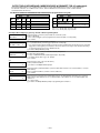
TO START PROGRAM MODE, use method A or B (must use alpha keypad connected to keypad terminals):
A. POWER UP, then press both [∗] and [#] at same time within 50 seconds of powering up.
(if ∗98 was used to exit program mode, this is the only method that can be used to start program mode again)
B. Initially, key: Installer Code (4 + 1 + 1 + 2) plus 8 + 0 + 0.
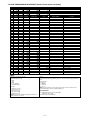
Data Field Programming Procedures
Task
Procedure
Go to a Data Field
Entering Data
Press [∗] + [Field Number], followed by the required entry.
When the desired field number appears, simply make the required entry. When the last entry for a field
is entered, the keypad beeps three times and automatically displays the next data field in sequence.
If the number of digits that you need to enter in a data field is less than the maximum digits available
(for example, the phone number fields *41, *42), enter the desired data, then press [∗] to end the entry.
Press [#] + [Field Number].
Data will be displayed for that field number. No changes will be accepted in this mode.
Review a Data Field
Deleting an Entry
Press [∗] + [Field Number] + [∗]. (Applies only to fields ∗40–*43, *45, *94, and pager programming
fields)
Menu Mode Programming (∗
∗56, 57, ∗58, ∗79, ∗80, ∗81, ∗82, ∗83)
Press [✱] + [Interactive Mode No.] (for example, ∗56). The alpha keypad displays the first of a series of prompts.
Interactive Mode
Used to Program
✱56 Zone Programming
Zone characteristics, report codes, alpha descriptors, and serial numbers for 5800 RF
transmitters.
✱57 Function Key Programming
Unlabeled keypad keys (known as ABCD keys) for special functions
✱58 Zone Programming
Same options as *56 mode, but with fewer prompts. Intended for those familiar with
(Expert mode)
this type of programming, otherwise *56 mode is recommended.
Assign module addresses and map individual relays/powerline carrier devices
✱79 Output Device Mapping
✱80 Output Programming
4229 or 4204 Relay modules, 6164 output relay, Powerline Carrier devices, or onboard triggers
✱81 Zone List Programming
Zone Lists for relay/powerline carrier activation, chime zones, pager zones, etc.
✱82 Alpha Programming
Zone alpha descriptors
✱83 Configurable Zone type Prog
Attributes for configurable zone types
INITIALIZE DOWNLOAD and RESET DEFAULTS (complete Default Tables are listed on page 20)
✱96 Initializes download ID and subscriber account number.
✱97 Sets all data fields to original factory default values as follows:
The VISTA-12A has two unique sets (tables) of default entries.
Press ∗97 while in Program Mode, then press 1 or 2 to load the desired set of factory defaults (see Default Tables
listed on page 20). This resets all data fields to the respective default table values.
User Code Defaults: To reset only the user codes to default values, press ∗97, then press 3.
TO EXIT PROGRAMMING MODE:
✱98 Exits programming mode and prevents re-entry by: Installer Code + 8 + 0 + 0. If ✱98 is used to exit programming
mode, system must be powered down, and method 1 above used to enter the programming mode.
✱99 Exits programming mode and allows re-entry by: Installer Code + 8 + 0 + 0 or method A above.
Special Messages
OC = OPEN CIRCUIT (no communication between keypad and Control).
EE or ENTRY ERROR = ERROR (invalid field number entered; re-enter valid field number).
After powering up, AC, dI (disabled) or Busy Standby and NOT READY will be displayed after approximately 4 seconds.
This will revert to a “Ready” message in approximately 1 minute, which allows PIRS, etc. to stabilize. You can bypass this
delay by pressing [#] + [0].
If E4 or E8 appears, more zones than the expansion units can handle have been programmed. Correct the programming
and then completely de-power and re-power the control to clear this indication and remove the disable indication.
–2–
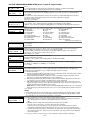
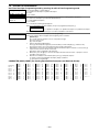
PR O GR A MM I N G F O R M
Entry of a number other than one specified will give unpredictable results. Default values are shown in brackets, with unique table 1 and table 2
values indicated where applicable (DT1 = default table 1; DT2 = default table 2); see page 20 for a complete list of factory default tables 1 and 2.
∗20
Installer Code
|
[4112]
|
∗38
|
0–9 = 4 digit installer code
∗21
Quick Arm Enable
Entry
0
1
2
3
4
5
6
7
8
9
#+10
#+11
#+12
#+13
#+14
#+15
DT1: [1,1,1] DT2: [0,0,0]
0 = no quick arm; 1 = allow quick arm
∗22
Part. 1 Part. 2 Com
RF Options
[0,0]
Entry 1 - 0 = no RF Jam detection; 1 = detect RF Jam
Jam Supv
Entry 2 – supervision interval; 0 = 12 hour; 1 = 2 hour; 2 = 20 min if
disarmed/2 hrs if armed; 3 = 12 hrs for burg zones/3 hrs for fire zones
∗23
Quick (Forced) Bypass
[0,0,0]
0 = no quick bypass
1 = allow quick bypass (code + [6] + [#])
∗24
RF House ID Code
Part. 1 Part. 2 Com
[00,00,00]
|
|
|
00 = disable all wireless keypad usage
Part. 1 Part. 2 Com
01–31 = house ID for use with 5827, 5827BD keypad or
5804BD/5804BDV keyfob
∗25
Arming Prevention Override
∗39
[7,0]
If no override is selected, system will not arm when there is either a
supervision failure, system low battery, AC loss, or tamper.
Entry 1 0 = no arming prevention override
1 = allow system to arm with an RF supervision failure
2 = allow system to be armed with an AC Mains Loss
4 = allow system to be armed with a system low battery
E.g., To select arm with “supervision failure” and “system low
battery”, enter 5 (1 + 4);
Entry 2 0 = no tamper override (see field *175 for more tamper options)
1 = allow system to be armed with a tamper fault
2 = allow system to be armed with a tamper fault once
NOTE: If tamper option 1 or 2 is selected, field *175 digit 2 must be “0.”
∗26
Chime By Zone
Powerline Carrier (X–10) House Code
∗40
∗41
∗42
ECP Contact ID Output for ACM
Single Alarm Sounding/Zone
[1]
Fire Alarm Sounder (Bell) Timeout
∗35
∗44
[60,60,60]
Entry Delay 2 (zone type 02)
∗38
∗46
Part 1 Part 2 Com
DT1: [0,0,0] DT2: [1,1,1]
Confirm. Arming Ding [03, 03, 03]
∗47
|
#+11| 2 | 3 | 4
|
|
Entry 1 for each partition selects
Part 1 Part 2 Com
whether arming from wired keypads causes siren ding:
0 = no; 1 = yes, ding and siren for time selected in entry 2
Entry 2 for each partition selects whether arming from keyswitch and/or
remote RF devices causes siren ding and/or activates trigger 2 output;
also selects ding/trigger activation duration (arm = 2 dings of selected
duration with 1 second off between; disarm = 1 ding of selected
duration).
|
|
|
|
|
|
|
|
|
|
|
|
|
|
|
|
Primary Subscriber ID # (Part. 2)
|
|
|
|
|
|
|
|
Secondary Subscriber ID # (Part. 2)
|
|
|
|
|
|
|
|
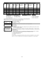
Phone System Select/Dialer Attempts
Phone System Select:
[1,6] Select Attempts
If Cent. Sta. IS NOT on a satellite link: 0=Pulse Dial; 1=Tone Dial;
if Cent. Sta. IS on a satellite link: 2 = Pulse Dial ; 3 = Tone Dial
Dialer Attempts: 1 – 10 (for 10, enter #+10)
Part 1 Part 2 Com
|
|
Secondary Subscriber ID # (Part. 1)
|
Audible Exit Warning
0 = no; 1 = yes
|
Primary Subscriber ID # (Part. 1)
|
[30,30,30]
See *35 for entries.
∗37
∗45
[15,15,15]
00 to 96 = 00 to 96 seconds respectively
Part 1 Part 2 Com
97 will = 120 seconds; 98 will = 180 seconds; 99 will = 240 seconds
∗36
; For Acct. B234, enter
1 | 2 | 3 | 4
|
Part 1 Part 2 Com
Entry Delay 1 (zone type 01)
|
Second Phone No.
|
[3]
00 to 96 = 00 to 96 seconds respectively
97 = 120 seconds
|
Primary Phone No.
1234, enter
∗43
Siren (Burglary) Timeout
Exit Delay
PABX Access Code
Enter up to 6 digits. If fewer than 6 digits are entered, exit by pressing
[✶]. To clear entries from field, press ∗40∗
[0]
0=none; 1 =1 min; 2 =2 min; 3 =3 min; 4 =4 min; 5 =8 min; 6 =16 min
∗34
[1]
Enter up to 30 digits for each phone number. To clear entries, press
∗41∗ or ∗42∗ respectively.
For fields *43, *44 , *45, *46, *51 and *52, enter 4, 6 (Robofon 8), or 10
digits, depending on selection in *48 Report Format. Enter 0–9; #+11 for B;
#+12 for C; #+13 for D; #+14 for E; #+15 for F. To clear entries from field,
press *43*, *44*, *45*, *46*, *51* or*52* respectively. Examples: For Acct.
[0]
0 = sounder stops at timeout; 1 = no sounder timeout
∗33
Power-Up In Previous State
| | | | | | | | | | | | | | | | | | | | | | | | | | | | |
0 = no; 1 = yes, only one alarm sounding per armed period per zone
∗32
NOTE:
If using trigger 2
output for arming
ding, do not assign
any other functions
to trigger 2.
[0]
0 = no; 1 = use Contact ID output on ECP terms. (e.g. TCP-IP ethernet)
∗31
Trigger 2 Output
none
250mS
1 second
4 seconds
none
250mS
1 second
4 seconds
none
250mS
1 second
4 seconds
none
250mS
1 second
4 seconds
| | | | | | | | | | | | | | | | | | | | | | | | | | | | |
0 = A; 1 = B, 2 = C, 3 = D, 4 = E, 5 = F, 6 = G, 7 = H, 8 = I, 9 = J,
#10 = K, #11 = L, #12 = M, #13 = N, #14 = O, #15 = P
∗29
Ding at Siren
none
none
none
none
250mS
250mS
250mS
250mS
1 second
1 second
1 second
1 second
4 seconds
4 seconds
4 seconds
4 seconds
0 = always power-up disarmed; 1 = power-up in previous state
For dialer fields ∗40 – ∗42, enter the number of digits shown. Do not fill
unused spaces. Enter 0–9; #+11 for '∗'; #+12 for '#'; #+13 for a 2-second
pause. If fewer than the maximum digits entered, exit the field by pressing [✶].
The next data field is displayed.
[0]
0 = no; 1 = yes (select chime zones on zone list 3, see *81 Menu mode)
∗27
Confirm. Arming Ding (continued)
(continued) Enter 0-15 from table.
∗48
(field *38 continued at top of next column)
–3–
Report Format
0 = 3+1,4+1, ADEMCO L/S STANDARD
1 = 3+1,4+1, RADIONICS STANDARD
2 = 4+2, ADEMCO L/S STANDARD
3 = 4+2, RADIONICS STANDARD
5 = CID using 10-digit subs account (ID) no.
6 = 4+2, ADEMCO EXPRESS
7 = CID using 4-digit subs account (ID) no.
8 = 3+1,4+1, ADEMCO L/S EXPANDED
9 = 3+1,4+1, RADIONICS EXPANDED
#+10 = ROBOFON 8 (6-digit subs account no.)
#+11 = ROBOFON Contact ID
[7,7]
prim. second
NOTES: To enable
audio “beeps” format
(Follow-Me feature),
refer to the System
Communication and
Operation section in
the Inst.Instr. Also see
*53 and *188 for
notes on certain
Contact ID codes.
∗49
Split/Dual Reporting
∗69
[0]
0 = Disable (standard/backup reporting only)
Primary Phone No.
Second Phone No.
1 = Alarms, Restore, Cancel
Others
2 = All except Open/Close, Test
Open/Close, Test
3 = Alarms, Restore, Cancel
All
4 = All except Open/Close, Test
All
5 = All
All
∗50
∗70
Alarm Restore Rpt Code
∗71
Trouble Restore Rpt Code
∗72
Bypass Rest. Rpt Code
∗73
|
Secondary Subscriber ID # (Common Part.)
Dialer Delay (Burg)
[0]
Primary Subscriber ID # (Common Part.)
|
∗52
|
|
|
|
|
|
|
|
|
|
|
|
|
|
|
|
Fields *51 and *52 see box above ∗43 for entries.
∗53
SESCOA/Radionics and CID Enbl
Dynamic Signaling Delay
|
DT1: [00] DT2: [10]
|
AC Restore Rpt Code
[10]
|
∗74
Low Bat Restore Rpt Code
[10]
|
∗75
RF Low Battery Restore Rpt Code
[10]
|
∗76
Test Restore Rpt Code
[10]
|
Summer Time Start\End Month
[00]
|
0 = Disabled; 1-12 = month (1 = January, 2 = February, etc)
#+10 = October; #+11 = November; #+12 = December
∗78
∗84
∗85
[0]
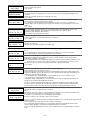
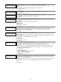
TO PROGRAM SYSTEM STATUS, & RESTORE REPORT CODES:
∗59
Exit Error Report Code
∗60
Trouble Report Code
[10]
|
∗61
Bypass Report Code
DT1: [00] DT2: [10]
|
∗62
AC Loss Report Code
[10]
|
∗63
Low Bat Report Code
[10]
|
Test Report Code
[10]
|
∗64
∗65
Open Report Code
DT1: [0,0,0] DT2: [1,1,1]
∗66
∗86
Part. 1 Part. 2 Com
Arm Away/Stay Rpt Code
∗87
AWAY STAY
Part. 2
AWAY STAY DT2: [1,0;1,0;1,0]
Common
∗67
RF Trans. Low Bat Report Code
∗68
Cancel Report Code
[10]
|
DT1: [10] DT2: [00]
|
Linked Zone Verification Timer/
[0,0]
Cancel Verify Keypad Display
[0]
Misc. Fault Delay Time
[0]
(for Configurable Zone Type zones - alarm/trouble processing option)
0 = 15 seconds
4 = 90 seconds 8 = 4 min
#+12 = 8 min
1 = 30 seconds
5 = 2 minutes 9 = 5 min
#+13 = 10 min
2 = 45 seconds
6 = 2-1/2 min #+10 = 6 min
#+14 = 12 min
3 = 60 seconds
7 = 3 min
#+11 = 7 min
#+15 = 15 min
∗88
Exit Options
[2]
0 = all intrusion zones must be intact before arming(must be 0 if
system uses zone type 82 - Blockschloss)
1 = All intrusion zones except in exit path (zone list 12) must be
intact before arming. Exit path zones cause alarm if not restored
at end of exit time
2 = All intrusion zones except in exit path (zone list 12) must be
intact before arming. Exit path zones are bypassed if not restored
at end of exit time
3 = Final contact set: All intrusion zones except in exit path (zone list 12)
must be intact before arming. Once armed, exit delay remains on
indefinitely until the last zone, as defined in zone list 8, is restored;
then there is 5-second exit delay before arming state is active
∗89
Event Log Full Report Code
[00]
|
See box above ∗59 for entries.
∗90
Event Log Enables
[15]
0 = None; 1 = Alarm/Alarm Restore; 2 = Trouble/Trouble Restore;
4 = Bypass/Bypass Restore; 8 = Open/Close. Ex: For “Alarm/Restore”
and “Open/Close”, enter 9 (1 + 8); To select all, enter #15.
NOTE: System messages logged when any non-zero entry is made.
DT1: [0,0;0,0;0,0]
AWAY STAY
Part. 1
[0]
0 = no “alarm canceled” display
1 = display “Alarm Canceled” when system is disarmed after an alarm
has occurred. (To clear the “ALARM CANCELED” display, the
user must enter the security code + OFF again.)
[0]
System default sets schedule 8 to send test reports for DT1: every
Wednesday at 2:00AM, and for DT2: daily at 2:00AM.
First test report sent 12 hours after exiting program mode.
Use Scheduling mode to change periodic test report schedule.
Auto Stay Arm
Up and About Timer
Linked Up/about
Linked Zone: Assign linked zones on zone list 4, with *81 Menu mode.
0 = 15 seconds
4 = 90 seconds 8 = 4 min
#+12 = 8 min
1 = 30 seconds
5 = 2 minutes 9 = 5 min
#+13 = 10 min
2 = 45 seconds
6 = 2-1/2 min #+10 = 6 min
#+14 = 12 min
3 = 60 seconds
7 = 3 min
#+11 = 7 min
#+15 = 15 min
Up and About Timer: 1-15 hours (also need to program up and about
schedule for time window that up and about feature is active; value set
in this field is time within the schedule that activity must occur)
0 = Primary Dialer first; 1 = ECP Contact ID first (e.g., TCP-IP ethernet)
For 3+1 or 4+1 Standard Format: Enter a code in the first box: 1–9, #+10 for
0, #+11 for B, #+12 for C, #+13 for D, #+14 for E, #+15 for F.
A 0 (not #+10) in the first box will disable a report. A 0 (not #+10) in the
second box will result in automatic advance to the next field.
For Expanded or 4+2 Format: Enter codes in both boxes (1st and 2nd digits)
for 1–9, 0, or B–F, as described above.
A 0 (not #+10) in the second box will eliminate the expanded message for
that report. A 0 (not #+10) in both boxes will disable the report.
For Ademco Contact ID® Reporting: Enter any digit (other than 0) in the first
box, to enable zone to report (entries in the second boxes are ignored).
A 0 (not #+10) in the first box disables the report.
|
[00]
0 = none; 1 = partition 1; 2 = partition 2; 4 = partition 3
Add the values for multiple partitions.
[0]
Dynamic Signaling Priority
Summer Time Start\End Weekend
0 = disabled; 1 = first; 2 = second; 3 = third
4 = fourth; 5 = last; 6 = next to last; 7 = third to last
Delay selectable from 0 to 225 secs in 15-sec increments.
0 = no delay (both signals sent); 1 = 15 secs; 2 = 30 secs, etc.
∗55
[1]
[10]
∗77
[0,0]
SESCOA/Radionics Select:
Ses/Rad CID
0 = Radionics (0-9, B-F); 1 = SESCOA (0-9)
CID Enable:
0 = disable both Time/Date Inaccurate and Successful
Download/Access reports
1 = enable Time/Date Inaccurate report (code 626)
2 = enable Successful Download/Access report (code 412)
3 = enable both Time/Date Inaccurate and Successful
Download/Access reports
NOTE: Time/Date Inaccurate report (CID 626) and Successful
Download/Access report (CID 412) are sent only if Contact ID format
is selected as reporting format in field *48.
∗54
[1]
Send restore code (if fault cleared):
0 = at siren timeout (if restored) or at disarm (whether restored or not)
0 = none; 1 = 15 seconds; 2 = 30 seconds; 3 = 45 seconds
∗51
Alarm Restores
∗91
Miscellaneous Options
[0,0]
Entry 1: 0 = None; 4 = Audio Alarm Verification (AAV);
1
2
8 = Exit Delay Restart; #+12 = AAV (4) and Exit Delay Restart (8)
Entry 2: 0 = allow keypad output activation commands
(user code + # + 7 and user code + # + 8)
1 = do not allow keypad output activation commands
1 = dynamically as the fault clears; 2 = only after a disarm
–4–
∗92
Telecom Monitor Enable
∗176 Siren Options
[0,0]
Entry 1: 0 = disabled
1
2
1-15 = enabled, after 1 15 min. line outage
(#+10 = 10 min; #+11 = 11 min; #+12 = 12 min;
#+13 = 13 min; #+14 = 14 min; #+15 = 15 min)
Entry 2: 0 = keypad display when line is faulted
1 = keypad display plus keypad trouble sound
2 = Same as “1”, plus programmed output device STARTS. If
any partition is armed, external sounder also activates.
NOTE: Output Device must either be programmed to be STOPPED
in field ∗80 or STOPPED by Code + # + 8 + output number.
∗93
No. of Reports in Armed Period
[6]
∗177 Device Duration 1, 2
Per Zone (Intermittent Sensor)
Download Phone No.
| | | | | | | | | | | | | | | | | | | | | | | | | | | | |
Enter up to 30 digits, 0–9; #+11 for '∗'; #+12 for '#'; #+13 for a 2second pause. Do not fill unused spaces. If fewer than 30 digits, exit
field by pressing ∗. To clear entries from field, press ∗94∗.
∗95
Ring Count For Downloading
∗178 RF Supervision and RF Jam Option
[0]
∗180 Zone Bypass Limit
| | | | | | | | | | | | | | | | | | |
Enter up to 20 digits, 0–9; #+11 for '∗'; #+12 for '#'; #+13 for a 2second pause. Do not fill unused spaces. If fewer than 20 digits, exit
field by pressing ∗. To clear entries from field, press ∗160∗.
∗181 AC and Clock Display Options
| | | | | | | | | | | | | | |
Enter the optional prefix characters, up to 16 digits.
0–9; #+11 = '∗'; #+12 = '#'; #+13 = 2-second pause.
∗162 Pager 1 Reporting Options
For each partition, select from:
[0,0,0] Part. 1 Part. 2 Part 3
0 = no reports sent; 1 = Open/close all users; 4 = All alarms and troubles
5 = All alarms / troubles, and open/closes for all users
12 = Alarms / troubles for zones entered in zone list 9
13 = Alarms / troubles for zones entered in zone list 9, and
opens/closes for all users
∗163 Pager 2 Phone No. (See field *160 for entries.)
| | | | | | | | | | | | | | | | | | |
∗164 Pager 2 Characters (See field *161 for entries.)
| | | | | | | | | | | | | | |
∗165 Pager 2 Reporting Options
Part. 1 Part. 2 Part 3
∗182 Summer Time Switchover Day
∗183 Date/Time Format
0 = 12-hour time/MMDDYY date
1 = 12-hour time/DDMMYY date
[1]
0 = none; 1 = RF Tamper reports during disarm
2 = RF keyfobs send low battery
3 = RF Tamper reports during disarm and RF keyfobs send low battery
[1]
2 = 24-hour time/MMDDYY date
3 = 24-hour time/DDMMYY date
∗185 Downloader Suppression Options
[0]
0 = no suppression; 1 = suppress user code viewing
2 = suppress commands and program download when armed
3 = suppress user code viewing, commands, and program download
when armed
[0,0]
(see field *25 for tamper override options when arming) 1
2
Entry 1: 0 = standard tamper protection
1 = detect tamper from bypassed zones
2 = detect tamper when in Test mode
3 = detect tamper when in Test mode from bypassed zones
Entry 2: 0 = all users can clear a tamper (must be “0” if field *25 digit
2 set to 1 or 2)
1 = only the installer can clear a tamper
[0]
0 = switch on Sunday morning; 1= switch on Saturday morning
2 = switch on Friday morning
[0]
0 = none, 1 = 1 minute, 2 = 2 minutes, 3 = 3 minutes
This delay is for ALL pagers in the system. The delay does not reset
for new alarms occurring while an existing pager delay is in progress.
∗175 Tamper Options
[13]
Use the following table to select the desired options for real-time
clock synchronization (50Hz, 60Hz, Crystal), AC Loss display
(independent of AC Loss report enabled in *62), and clock display
(time displayed on bottom line of alpha keypads).
“X10” indicates the AC frequency used for powerline carrier devices.
Entry
AC Freq.
Crystal for AC Loss disp Clock disp
0
60Hz
clock backup
no
no
1
50Hz
clock backup
no
no
2
60Hz
clock
no
no
3
50Hz
clock
no
no
4
60Hz
clock backup
yes
no
5
50Hz
clock backup
yes
no
6
60Hz
clock
yes
no
7
50Hz
clock
yes
no
8
60Hz
clock backup
no
yes
9
50Hz
clock backup
no
yes
#+10
60Hz
clock
no
yes
#+11
50Hz
clock
no
yes
#+12
60Hz
clock backup
yes
yes
#+13
50Hz
clock backup
yes
yes
#+14
60Hz
clock
yes
yes
#+15
50Hz
clock
yes
yes
∗161 Pager 1 Characters
∗173 RF Reporting Options
[0]
0 = unlimited zone bypasses in each partition
1-7 = number of zone bypasses allowed in each partition
(each partition individually uses this entry)
8 = zone bypass disabled (no zones can be bypassed)
∗160 Pager 1 Phone No.
∗166 Pager Delay Option For Alarms
[0]
0 = Basic RF supervision and RF jam detection
1 = Report RF supervision failure as tamper alarm when armed
2 = Report RF Jam as tamper alarm when armed
3 = Report RF Jam & RF supervision failure as tamper alarm when armed
0 = Disable Monitoring Station Initiated Download;
1–14 = number of rings (1–9, # +10 =10, # +11 =11, # +12 =12,
# +13 =13, # +14 =14);
15 = Answering machine/fax defeat (# +15 =15).
See field *162 for entries.
[0,0,0]
Use zone list 10 if using options 12 or 13.
[0,7]
(used in *80 Output Definitions menu -Device Actions 5/6) 1
2
Duration 1 – Device Action 5 Timer
0 = 15 seconds
4 = 90 secs
8 = 4 min
#+12 = 8 min
1 = 30 seconds
5 = 2 min
9 = 5 min
#+13 = 10 min
2 = 45 seconds
6 = 2-1/2 min #+10 = 6 min
#+14 = 12 min
3 = 60 seconds
7 = 3 min
#+11 = 7 min
#+15 = 15 min
Duration 2 – Device Action 6 Timer (Strobe Timer)
1 – 7 = 1 to 7 days
0 = Unlimited Reports; 1 - 6 = 1 - 6 report pairs
∗94
DT1: [0,2] DT2: [0,0]
Entry 1: 0 = external siren; 1 = self-activated external siren 1 2
Entry 2: 0 = disable (2nd digit ignored if 1st digit not set to ext. siren)
1 = enable 30 second ext. siren and dialer delay during entry
delay period when armed AWAY (if entry delay is active
and an instant zone is faulted, the siren is delayed 30
seconds, and the report is delayed 30 secs. unless field
*50 is set for a greater delay)
2 = external siren and dialer delayed 15-seconds when
armed in STAY mode
∗186 Display Options
[0,0]
Entry 1: Latch the first alarm in the display: 0 = disable; 1 = enable
Entry 2: Turn off the display (except for AC loss) except during exit
delay. Turns off when exit delay expires, or 30 seconds after
disarm; 0 = disable; 1 = enable
–5–
∗187 Sounder Mimic on Trigger 1
KEYPAD OPTIONS
[0]
NOTES: 1. Keypad 1 (addr 16) options are factory set and cannot be changed.
2. Each keypad must be assigned a unique address. Keypads
programmed with the same address will give unpredictable results.
0 = no sound output on trigger 1
1 = mimic keypad 1, address 16 5 = mimic keypad 5, address 20
2 = mimic keypad 2, address 17 6 = mimic keypad 6, address 21
3 = mimic keypad 3, address 18 7 = mimic keypad 7, address 22
4 = mimic keypad 4, address 19 8 = mimic keypad 8, address 23
NOTE: If used, do not assign any other functions to trigger 1.
∗188 Keypad Sabotage Options
∗190 Keypad 2 Device Address 17
[0,0]
Entry 1: Keypad Lockout: 0 = disable; 1 = enable 15 minute lockout
NOTE: 461 Wrong Code Entry is sent only if Contact ID
format is selected as reporting format in field *48 (if
Contact ID format is not being used, this event is not
reported)
Entry 2: Keypad Supervision and Tamper Fault Detection:
0 = no, 1 = yes
NOTE: All lockout, supervision, and tamper events are recorded in
the event log regardless of the settings in entries 1 and 2.
∗189 AUI Device 1 and 2 Enable
[0,0]
(for Touch Screen Style Keypads)
AUI 1 AU2
System supports up to two touch screen style keypads (e.g., Symphony
Advanced User Interface, and 6270 Touch Screen Keypad).
AUI Compatibility Note: To ensure proper AUI device operation, use
AUI devices with the following rev levels: 6270 series use version
1.0.9 or higher; 8132/8142 (Symphony) series use version 1.1.175 or
higher.
Touch Screen (AUI) device 1: Must set AUI device address to 1
Touch Screen (AUI) device 2: Must set AUI device address to 2
Enter each AUI’s home partition.
0 = disabled
1 = partition 1; 2 = partition 2; 3 = common partition
[0] [0]
Partition: 0 = keypad disabled; 1-3 = part. no.
Part.
Sound: 0 = no suppression
1 = suppress arm/disarm and E/E beeps
2 = suppress chime beeps only
3 = suppress arm/disarm, E/E, & chime beeps
Fields*191-*196 see field ∗190 for entries.
Part.
∗191 Keypad 3 Device Address 18
[0] [0]
∗192 Keypad 4 Device Address 19
[0] [0]
∗193 Keypad 5 Device Address 20
[0] [0]
∗194 Keypad 6 Device Address 21
[0] [0]
∗195 Keypad 7 Device Address 22
[0] [0]
∗196 Keypad 8 Device Address 23
[0] [0]
∗197 Exit Time Display Interval
Sound
Sound
[1]
0 = no display; 1-5 = seconds between display refresh
∗198 Display Partition Number
[0]
0 = no; 1 = yes (partition number displays on alpha keypads)
∗199 ECP Device Fail Display
0 = 3-digit display (“1” + device address); for 6148, 6164
1 = 2-digit fixed-display as “91;” for 6128 series keypads
–6–
[0]
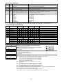
*56 ZONE PROGRAMMING WORKSHEET [default values shown in brackets]
Zone Zn Type Partition
1
2
3
4
5
6
[01]
[04]
[03]
[03]
[03]
[03]
Report
[1]
[1]
[1]
[1]
[1]
[1]
Zone Zn Type Partition
9
10
11
12
13
14
15
16
17
18
19
20
21
22
23
24
[1]
49
[1]
50
[1]
51
[1]
52
[1]
53
[1]
54
[1]
55
[1]
56
[1]
57
[1]
58
[1]
59
[1]
60
[1]
61
[1]
62
[1]
63
[1]
64
[05]
N/A
91
N/A
N/A
92
[00]
95
[00]
96
[07]
99
[yes]
[yes]
[yes]
[yes]
[yes]
[yes]
Report
[yes]
[yes]
[yes]
[yes]
[yes]
[yes]
[yes]
[yes]
[yes]
[yes]
[yes]
[yes]
[yes]
[yes]
[yes]
[yes]
[yes]
[yes]
Basic Wired Type Response Time
[EOL]
[EOL]
[EOL]
[EOL]
[EOL]
[EOL]
Input Type
[BR]
[BR]
[BR]
[BR]
[BR]
[BR]
[BR]
[BR]
[BR]
[BR]
[BR]
[BR]
[BR]
[BR]
[BR]
[BR]
N/A
N/A
N/A
N/A
N/A
Location
[1]
[1]
[1]
[1]
[1]
[1]
Loop
Serial Number
N/A
N/A
N/A
N/A
N/A
N/A
N/A
N/A
N/A
N/A
Location
Addressable Device Report
Duress Report
keypad [1] / [∗]
keypad [3] / [#]
keypad [∗] / [#]
NOTES:
Zone Type: see chart on next page
Basic wired Type (zns 1-6):
0 = EOL
1 = NC
2 = NO
3 = zone doubling
4 = double-balanced
Input Type:
2 = AW (zones 17-24)
3 = RF (zones 9-24)
4 = UR (zones 9-24)
5 = BR (zones 49-64)
7 = RM (zones 9-24)
NOTE: Zones 9-14 not available depending on whether zone
doubling enabled on zones 1-6.
Report:
yes = Contact ID reporting enabled for this zone; entered as 01 00 in appropriate data
fields.
Response Time:
0 = 10msec
1 = 400msec
2 = 700msec
3 = 1.2 sec
NOTE: If zone doubling is selected, the response time selected for the basic zone
automatically applies to the associated doubled zone.
Reserved Zones
91 = addressable device report enable/disable
default zone type = [05].
92 = Duress report enable/disable
–7–
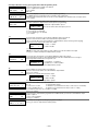
∗56 ZONE PROGRAMMING MENU MODE (press *56 while in Program mode)
SET TO CONFIRM?
0 = NO 1 = YES
0 = no
1 = yes (prompt appears after entering the serial and loop numbers to confirm each transmitter)
We recommend that you confirm the programming of every transmitter.
Enter Zn Num.
(00 = Quit)
Enter the zone number being programmed:
wired zones 01-6 and 10-14 for zone doubling; expansion zones 17-24; wireless zones 09-24; RF button
zones 49-64
91 = addr. device report enable (Enter a report code for zone 91 to enable addressable device reporting.
92 = duress report enable (Enter a report code for zone 92 to enable duress reporting)
95, 96, 99 =emergency zones
00 to quit; [∗] to continue
Zn ZT P RC
10 00 1 10
10
Summary Screen
[∗] to continue; “IN: L” = input type and loop; “IN: AD” = wired expansion module address
“HW: RT” = basic wired zone configuration (EOL, NO, NC, zone doubling, double-balanced) and response
time
In: L
RF: 1
10 Zone Type
Perimeter
03
Enter the desired partition for this zone
1-3 = partition
[∗] to continue
10 Partition
1
10 Report Code
1st 01 2nd 00
10
0
This prompt appears only for basic wired zones 01-06 (zone 02 is used as an example in display).
0 = 10mSec; 1 = 400mSec; 2 = 700mSec; 3 = 1.2 seconds
[∗] to continue
02 Response Time
1
This prompt is skipped for zones 1-6, and for zones 9-14 if zone-doubling enabled at “Hardwire Type” prompt.
All of the RF transmitters have one or more unique input loops (see list below). Each of the input loops
requires its own programming zone (e.g., a 5804's four inputs requires four zones).
2 = AW (Aux wired zone)
3 = RF (supervised RF transmitter; sends fault, restore, and low-battery signals, and sends periodic check-in
signals; transmitter must stay within receiver's range)
4 = UR (unsupervised RF transmitter; sends fault, restore, and low-battery signals, but periodic check-in
signals are not supervised; transmitter may be carried off-premises)
5 = BR (unsupervised button type RF transmitter; sends fault and low battery signals when activated, does
not send restore or check-in signals; transmitter may be carried off-premises)
7 = RM (supervised RF motion detector; sends fault and low battery signals, and sends periodic check-in
signals; panel ignores detector restore signals but automatically restores the zone to “ready” after a few
seconds; transmitter must stay within receiver's range)
NOTE: While the system is disarmed, faults from input type RM devices might not be seen on the keypad
display because the subsequent automatic restore can occur more quickly than the display is refreshed.
[∗] to continue
10 INPUT TYPE
RF TRANS
Enter the report code for this zone, which consists of 2 hexadecimal digits, each in turn consisting of 2
numerical digits. For example, for a report code of “10,” enter 01 and 00.
For Contact ID®, entering any non-zero entry as the first digit enables the report code for this zone.
1-9, 10 for A, 11 for B, 12 for C, 13 for D, 14 for E, 15 for F
00 to disable; [∗] to continue
This prompt appears only for zone numbers 01-06.
Enter the desired basic wired type:
0 = EOL; 1 = NC; 2 = NO; 3 = zone doubling (ZD); 4 = double-balanced (DB)
[∗] to continue
02 HARDWIRE TYPE
EOL
Enter the desired ;zone type from the list below. If 00 is entered, Delete Zone ? is displayed.
00 = Not used
08 = 24-Hr Aux
21 = Arm–AWAY*
01 = Entry/exit #1
09 = Fire
22 = Disarm*
02 = Entry/exit #2
10 = Interior w/Delay
23 = No Alarm Resp
03 = Perimeter
12 = Monitor Zone
24 = Silent Burglary
04 = Interior Follower
14 = Gas
77 = Keyswitch
05 = Trouble Day/Alarm Night
15 = Medical
81 = AAV Monitor Zone
06 = 24-Hr Silent
16 = Fire w/Verify
82 = Blockschloss Keyswitch
20 = Arm–STAY*
90-93 = Configurable
07 = 24-Hr Audible
*5800 button-type transmitters only
3
NOTES:
• For the built-in basic wired zones, the Input Type is automatically displayed as HW and cannot be edited.
• To change the input type of a previously programmed wireless device (type RF, UR, BR, RM) to a wired
zone (type AW), you must first delete the transmitter’s serial number.
10 INPUT S/N:
A022-4064
L
1
For wireless transmitters, enroll the serial number and loop number as follows:
1. a. Transmit two open/close sequences. If using a button-type transmitter, press and release the button
twice, but wait about 4 seconds before pressing the button the second time.
OR
b. Manually enter the 7-digit serial number printed on the label of the transmitter.
Press the [∗] key to move to the “L” position, then enter the loop number.
If desired, you can press the [C] key to copy the previously enrolled serial number (used when
programming a transmitter with several input loops). The cursor moves to the loop number position.
c. To delete an existing serial number, enter 0 in the loop number field. The serial number will change to
0's. If 0 was entered in error, simply re-enter the loop number or press [#], and the serial number will
return to the display.
2. Press [∗] to continue. The system now checks for a duplicate serial/loop number combination.
–8–
10 INPUT S/N
L
A022-4064
1
XMIT TO CONFIRM
PRESS ✱ TO SKIP
Entd A022-4063 1
Rcvd A022-4064 1
Zn ZT
RC
10 03 10
In: L
RF: 1s
PROGRAM ALPHA?
0 = NO 1 = YES
0
ENTER ZN NUM.
(00 = QUIT)
11
If the serial/loop number combination is not a duplicate in the system, a display showing the serial number
and loop number entry appears.
[∗] to continue
This prompt will only appear if you answered “Yes” at the first prompt in this section.
The system will enter a confirmation mode so that the operation of the actual programmed input can be
confirmed.
Activate the loop input or button that corresponds to this zone.
[∗] to continue
If the serial/loop number transmitted does not match the serial number entered, a display showing the
entered and the received serial/loop numbers appears.
If so, activate the loop input or button on the transmitter once again. If a match is not obtained (i.e.,
summary display does not appear), press the [#] key twice and then enter (or transmit) the correct serial
number.
[∗] to continue
If the serial number transmitted matches the serial number entered, the keypad will beep 3 times and
a summary display will appear, showing that zone's programming. An “s” indicates that a
transmitter’s serial number has been enrolled.
[∗] to accept the zone information and continue
If you want to program descriptors for zones now, enter 1 (Yes) and refer to the *82 Descriptor Programming
section for procedures. To program descriptors later, enter 0 (no).
[∗] to continue
If 0 (No) was entered at the Program Alpha prompt, the system will return you to the ENTER ZN NUM.
prompt for the next zone.
When all zones have been programmed, enter 00 to quit.
∗58 Expert Programming Mode Procedures (press ∗58 while in Data Programming mode)
SET TO CONFIRM?
0 = NO 1 = YES
Zn ZT P RC HW: RT
01 09 1 10
EL
1
Zn ZT P RC IN: L
10
–
–
–:
–
Zn ZT P RC IN: L
10 00 1 10 RF 1
0 = no
1 = yes (prompt appears after entering the serial and loop numbers to confirm each transmitter)
We recommend that you confirm the programming of every transmitter.
A summary screen will appear, showing zone 1’s currently programmed values.
Enter the zone number being programmed, then press [∗]. In this example, zone 10 is being entered.
01-06, 09-24, and 49-64 = zone number
[D] = for assigning wireless key programming templates (see Wireless Key Programming Templates section
in i/i); lets you choose from a series of preset templates for easy programming of wireless key zones
00 = quit (when all zones have been programmed, press “00” to quit this menu mode)
[∗] to continue
A summary screen with the selected zone’s current programming appears.
Begin programming zone information as follows:
Enter Zone Type (ZT; see Zone Type chart shown in *56 Menu Mode “Zone Type” prompt), Partition (P),
Report Code (RC) 0-9 only (use *56 mode for hex codes), and Input Device Type (IN)* sequentially (Loop
Number (L) is entered at the next prompt).
• Use the [A] (Advance) and [B] (Back) keys on the keypad to move the cursor within the screen.
• Use the [C] key to copy the previous zone’s attributes.
* If HW (basic wired) or AW (Auxiliary) is entered for Input Device Type, the display will be similar to the
prompt shown, except that HW or AW will be under “IN”.
Press [∗] to save the programming and continue. If needed, press the [#] key to back up without saving.
For wireless devices (input types RF, UR, BR, RM), continue to the serial number/loop number prompt.
For wired devices, return to the initial summary screen prompt to begin programming the next zone.
10 INPUT S/N:
AXXX-XXX
L
–
Zn ZT P RC In
L
10 03 1 10 RF: 1s
Manually enter the serial number (found on the transmitter label), by entering the digits in the “X” locations,
using the [A] (advance) or [B] (back) keys as required.
OR
Transmit two open/close sequences. If using a button-type transmitter, press and release the button twice,
but wait about 4 seconds before pressing the button the second time.
If you want to copy the previous zone’s serial number, press the [C] key.
Press [∗] to advance to the loop number, then enter loop number.
Press [∗] to accept the existing serial and loop number and continue to the “Confirm” prompt described in *56
Menu mode above.
If necessary, press [#] to back up and re-enter or edit the serial number.
If the serial number transmitted matches the serial number entered, the keypad will beep 3 times and a
summary display will appear, showing the programmed information for that zone.
Press [∗] to begin programming the next zone. See first “Summary Screen” prompt paragraph on previous
page.
–9–
Wireless Key Programming Templates (press the [D] key from *58 Menu mode Summary Screen display)
This procedure programs the wireless keys, but a key is not active until it is assigned to a user number (see System Operation section,
assigning attributes command in the Installation Instructions).
Enter desired template number 1–6 (see chart below).
Press [#] if you want to return to *58 Menu mode Summary Screen.
If necessary, press [#] to back up and re-enter template number.
Press [∗] to continue to template display.
TEMPLATE ?
1
L
01
02
03 04
T
23
22
21 23
When [∗] is pressed, the selected template will be displayed.
Top line of display represents loop numbers, bottom line represents zone type assigned for each loop.
Press [∗] to accept template and continue.
Enter the partition in which the key is to be active.
1 = partition 1; 2 = partition 2; 3 = common partition
Press [∗] to continue.
PARTITION
1
The system will search for the highest available consecutive 4-zone group (the four zones in the case of the
5804), and display the lowest zone number of the group.
If you want to start at a different zone, enter the zone desired, and press [∗]. If that zone number is
displayed, the system has the required number of consecutive zones available, beginning with the zone you
entered. If not, the system will again display a suggested zone that can be used.
If the required number of consecutive zones is not available at all, the system will display “00”.
Press [∗] to accept and continue.
ENTER START ZONE
00 = QUIT
36
INPUT S/N
L
AXXX-XXXX
–
Manually enter the serial number printed on the label for the wireless key or press and release the button to
transmit its serial number.
Press [∗] to accept the serial number. The system will check for duplicate.
If necessary, press the [#] key to back up without saving, and re-enter the serial number.
Use the [A] key to move forward within the screen, and the [B] key to move backward.
If “Yes” was entered at the SET TO CONFIRM? prompt (first prompt following entry into the ∗58 Expert
Programming Mode), the display on the left will appear.
Confirm serial and loop numbers by activating the wireless key. Refer to the “Confirm” prompt described in
*56 Menu mode above for more information on confirming the serial number.
If the serial number transmitted matches the serial number entered, the keypad will beep 3 times and will
return you to the ENTER START ZONE NUMBER prompt to enter the starting zone for the next wireless key.
IMPORTANT: When confirmed, the key is not active until it is assigned to a user number (using the
assigning attributes command, attribute “4”). See System Operation section in Installation Instructions.
[∗] to skip confirm.
XMIT TO CONFIRM
PRESS ✱ TO SKIP
Wireless Key Predefined Default Templates
5804
Loop Function
TEMPLATE 1
TEMPLATE 2
TEMPLATE 3
1
2
3
4
1
2
3
4
1
2
3
4
No Response
Disarm
Arm Away
No Response
No Response
Disarm
Arm Away
Arm Stay
24-hour audible
Disarm
Arm Away
Arm Stay
Zone Type
23
22
21
23
23
22
21
20
7
22
21
20
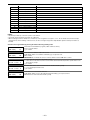
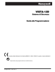
5800 Series Transmitter Input Loop Identification
All of the transmitters illustrated below have one or more
unique factory assigned input (loop) ID codes. Each of the
inputs requires its own programming zone (e.g., a 5804's
four inputs require four programming zones).
5804BD/5804BDV Loop
Function
TEMPLATE 4
No Response
No Response
Arm Away
Disarm
No Response
Arm Stay
Arm Away
Disarm
24-hour audible
Arm Stay
Arm Away
Disarm
1
2
3
4
1
2
3
4
1
2
3
4
TEMPLATE 5
TEMPLATE 6
LOOP 3
LOOP 4
YOU MUST
ENROLL
THIS
BUTTON
LOOP 2
ON O
F
5802MN2
ENROLL AS
"UR" OR "RF"
F
LOOP 2
(AUX.
CENTER
LOOP 1
(TERMINALS)
LOOP 1
5801
ENROLL AS
"UR" OR "RF"
LOOP 4
YOU MUST
ENROLL
THIS
BUTTON
23
23
21
22
23
20
21
22
7
20
21
22
LOOP 2
(REED)
LOOP
1
LOOP 3
Note: For information on any transmitter not shown, refer
to the instructions accompanying that transmitter
for details regarding loop numbers, etc.
Zone Type
5816
ENROLL AS "RF"
LOOP 2
LOOP 4
YOU MUST
ENROLL
THIS BUTTON
LOOP 2
LOOP 1
LOOP 3
LOOP 3
(AUX.
RIGHT)
LOOP 1
(PRIMARY)
5817
ENROLL AS "RF"
LOOP 2
(REED)
LOOP 2
(REED)
LOOP 3
(TERMINALS)
LOOP 1
(INTERNA
SHOCK
SENSOR
LOOP 1
SET
HOUSE
CODE
5804
ENROLL AS "BR"
5804BD
ENROLL AS "BR"
LOOP 1
5809
ENROLL AS "RF"
– 10 –
5819
ENROLL AS "RF"
LOOP 2
(REED)
5808
ENROLL AS "RF"
LOOP 1
LOOP 3
(TERMINALS)
LOOP 1
(TERMINALS)
LOOP 1
(MOTION)
LOOP 1
(TERMINALS)
ALTERNATE
POSITION
FOR LOOP 2
5816MN
ENROLL AS "RF"
5819S (WHS & BRS)
ENROLL AS "RF"
(Green)
(Red)
(Yellow)
5852 (GBD)
ENROLL AS "RF"
5890
ENROLL AS
"RF" OR "RM"
VISTA48A 001 V0
1–6
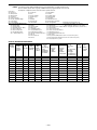
Table of Device Addresses
Address
Report† Device
00
01
02
03
017-23
100
101
102
103
117-123
08
13
16
17
18
19
20
21
22
23
28
Programmed by…
RF Receiver
*56 zone programming: input device type entry;
AUI Device 1
Automatic if AUI enable field *189 enabled for AUI 1
AUI Device 2
Automatic if AUI enable field *189 enabled for AUI 2
Alternative Communication Media (ACM)
automatic if ECP Contact ID Output for ACM field *29 enabled
Telecommand Voice Module
same as keypad enables; see below
Zone Expanders (4219/4229)/6164 Keypad:
*56 zone programming: input device type entry, then:
108
module 2 zones 17 - 24 / 6164 zones 17-20
• automatic if zone no. 17-24 entered as AW type or relay assigned
Relay Modules (4204)/6164 Keypad with Relay: *79 output device programming: device address prompt:
113
module 2 / 6164 using relay only (no zones)
• entered at device address prompt
Keypads:
data field programming as listed below:
n/a
keypad 1
• always enabled for partition 1, all sounds enabled.
n/a
keypad 2
• data field *190
n/a
keypad 3
• data field *191
n/a
keypad 4
• data field *192
n/a
keypad 5
• data field *193
n/a
keypad 6
• data field *194
n/a
keypad 7
• data field *195
n/a
keypad 8
• data field *196
n/a
5800TM Module
automatic
† Addressable devices are identified by “1” plus the device address when reporting. Enter report code for zone 91 to enable addressable device
reporting (default = reports enabled). See field *199 for addressable device (ECP) 3-digit/2-digit identification keypad display options.
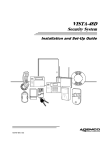
*57 FUNCTION KEY PROGRAMMING
Option
Function
P1
A
P2 P3
P1
B
P2 P3
P1
C
P2 P3
P1
D
P2 P3
Comments
Paging
Time Display
Arm AWAY
Arm STAY
Arm NIGHT-STAY
Step Arming
Device Activation
Device:
Comm. Test
Macro Key 1
Assign each macro key to only a single partition. †
Macro Key 2
Assign each macro key to only a single partition. †
Emergency Keys:
zone 95
zone 99
zone 96
paging
Personal Emergency
n/a
Silent Alarm
n/a
Audible Alarm
n/a
Fire
n/a
Emergency Keys:
A = paired keys [1] / [∗] (zone 95); B = paired keys [∗] / [#] (zone 99); C = paired keys [3] / [#] (zone 96)
† There are only four macros system-wide.
Start Function Key Programming mode by pressing ∗57 while in Data Programming mode.
Press the desired function key, A-D.
Press Key to Pgm
NOTE: A key programmed as a function key is no longer available to
be used as an end-user macro key or panic key.
0 = Quit
0
[∗] to continue
Partition
1
Key "A" Func
Zone 95
00
A
1
OFF
2
AWAY
3
STAY
B
4
MAX
5
TEST
6
BYPASS
C
7
INSTANT
8
CODE
9
CHECK
D
*
READY
0
#
keypad_keys-00-001-V0
01
02
03
04
05
06
07
08
09
10
00
1 = function key active in partition 1
2 = function key active in partition 2
3 = function key active in common partition
[∗] to continue
Enter the desired function for this key:
00 = For the Function key selected, the function will be as follows (system default):
If A selected = Zone 95 (emergency key, same as [1] [∗] pair)
If B selected = Zone 99 (emergency key, same as [∗] [#] pair)
If C selected = Zone 96 (emergency key, same as [3] [#] pair)
If D selected = Single-button paging
01 = Single-button paging (sends a 999-9999 message to pager)
02 = Display time
03 = Arm AWAY (reports as User 00 if closing reports are enabled)
04 = Arm STAY (reports as User 00 if closing reports are enabled)
05 = Arm NIGHT-STAY (reports as User 00 if closing reports enabled)
06 = Step Arming (arms STAY, then NIGHT-STAY, then AWAY)
07 = Output Device Command (for device programmed as system operation type 66 in *80 Menu Mode)
08 = Communication Test (sends Contact ID code 601)
09 -10= Macro Keys 1-2 respectively (defined by [#] [6] [6] command)
[∗] to continue; returns to key number prompt with the next function key letter displayed.
– 11 –
OUTPUT RELAYS/POWERLINE CARRIER DEVICES WORKSHEET FOR ∗79, ∗80 and ∗81.
For keypad activated devices, use *79 Menu mode to assign a system output number and associate its corresponding device.
For automatic activation, use *79 Menu mode as above, and use *80 Menu mode to define the system condition that will
activate/deactivate the device(s).
∗79 RELAY/POWERLINE CARRIER DEVICE MAPPING (Must program before using *80)
OUTPUT TYPE
Relay
X10
Output Module Pos
Unit Description
No.
Addr. (1-4)
No.
01
02
03
04
OUTPUT TYPE
Relay
X10
Output Module Pos
Unit
No.
Addr. (1-4)
No.
On-Board Trigger 1
17
On-Board Trigger 2
18
Description
Norm output =
Norm output =
[default: 1, trig. normally low
To Activate/Deactivate Devices in Normal Operating Mode:
Code + # + 7 + NN Key Entry starts Device NN.
Code + # + 8 + NN Key Entry stops Device NN.
Start Output Device Mapping by pressing *79 while in Data Programming Mode.
Enter the logical (or reference) relay number as used in the system.
ENTER OUTPUT NO.
01-04 = relays/X-10
00 = QUIT
xx
17-18 = on-board triggers (can be programmed for inverted output; see next prompt)
[∗] to continue
17 OUT NORM LOW
0 = NO 1 = YES
0
XX OUTPUT TYPE
DELETE?
0
This prompt appears only for triggers 17 and 18.
0 = no (standard default); sets the trigger output level normally high
1 = yes; sets the trigger output normally low (can be used for resetting 4-wire smoke detectors by connecting
trigger wire to the negative power terminal of the smoke detector, selecting 1 at this prompt, and setting
as zone type 54, fire zone reset, in *80 Menu mode)
[∗] to return to Output Number prompt
Select whether this is a relay or a Powerline Carrier (X-10) device.
0 = delete this output number
1 = relay on 4204/4229 module, 6164 keypad (skip to “B” prompt)
2 = Powerline Carrier device (go to “A” prompt)
[∗] to continue
“A”
XX UNIT No.
yy
Enter the device’s unit code (set at the device)
01-04 = predefined address
[∗] to returns to the Output Number prompt
“B”
yy
Enter the module’s predefined address (set the module’s DIP switches to the selected address, or key the
6164 address)
07-15 = predefined address (see table of device addresses)
[∗] to continue
zz
Enter the actual (or physical) relay number with respect to the Relay Module upon which it is located. For
4204 modules, relay numbers are 1-4. For 4229 modules, relay numbers are 1-2. For 6164 keypad, relay
number is 1.
1-4 = relay position
[∗] to return to the Output Number prompt for programming the next device
XX MODULE ADDR
07-15
XX REL POSITION
1-4
– 12 –
✱80
OUTPUT DEFINITIONS
NOTES: 1. For Relays, 4229, 4204 and 6164 devices are programmed in *79, *80, and *81 modes.
2. For Powerline Carrier devices (plcd), field ✱27 must be programmed with a House Code.
3. Tampers of expansion units cannot be used to operate devices.
Zone Types:
00 = Not used
01 = Entry/exit #1
02 = Entry/exit #2
03 = Perimeter
04 = Interior Follower
05 = Trouble Day/Alarm Night
06 = 24-Hr Silent
07 = 24-Hr Audible
Choices for System Operation are:
20 = Arming–Stay
21 = Arming–Away
22 = Disarming (Code + OFF)
31 = End of Exit Time
32 = Start of Entry Time
33 = Any Burglary Alarm
36 = **At Siren Timeout***
08 = 24-Hr Aux
09 = Fire
10 = Interior w/Delay
12 = Monitor Zone
14 = Gas
15 = Medical
16 = Fire w/Verify
20 = Arm–STAY*
21 = Arm–AWAY*
22 = Disarm*
23 = No Alarm Resp
24 = Silent Burglary
77 = Keyswitch
81 = AAV Monitor Zone
82 = Blockschloss Keyswitch
90-93 = Configurable
38 = Chime
39 = Any Fire Alarm
40 = Bypassing
41 = **AC Mains Failure
42 = **System Battery Low
43 = Communication Failure
46 = System Low Battery Restore**
52 = Kiss off
54 = Fire Zone Reset
58 = Duress
*5800 button-type transmitters only
** Use 0 (Any) for Partition No. (P) entry.
60 = AAV Trigger
*** Or at Disarming, whichever occurs earlier.
66 = Function key (use *57 Menu Mode to assign the function key, function “07,”)
67 = Siren Failure
68 = Telecom Line Fault
69 = Telecom Line Fault Restore
70 = AC Mains Restore**
71 = System Startup/Clock Not Set
72 = Clock Set
78 = Keyswitch red LED (device action not used for this option)
79 = Keyswitch green LED (device action not used for this option)
80 = any tamper in the system
OUTPUT DEFINITION WORKSHEET
Output
Activation Type and Detail
Event (for zone list/activated by)
Partition
Function Activated by Zone List Zone Type Zone No.
Number
By Zone List
By Zone No.
Number 0=delete
(P)
(ZN)
(ZL)
(ZT)
(if
using
ZT
trig)
(1-12)
0 = restore
1=zn list
0 = restore
1-12 = list (see table 00=none
1 = alarm
2=zn type
1 = alarm
below) 01-06, 09- 0 = any
1 = partition 1 2 = fault
24, 49-64
3=zn no.
2 = fault
2 = partition 2 3 = trouble
3 = trouble
3 = common
4 = off-normal
Output
Device
Action
Number
Type
0 = off
1 = close 2
1-18= dev R = relay
secs
T = trigger
2 = stay closed
X = X10
3 = pulse
4 = toggle
5 = duration 1††
6 = duration 2††
1
2
3
4
5
6
7
8
9
10
11
12
†† Duration is set in program field *177. Duration 1 (action 5) is from 15 seconds to 15 minutes. Duration 2 (action 6) is from 1 day to 7 days.
– 13 –
Start Output Definition mode by pressing ∗80 while in Data Programming mode.
Enter the output function number to be defined
Output Funct. #
01-12 = output function number
[∗] to continue
(00 = Quit)
01
00 = exit
01
A E P Trig
?00 0
0
– ZL=1
This screen displays a summary of the current output programming
A = Output Action; E = Triggering event; P = Partition; Trig = Trigger type
Question mark indicates the device shown has not been mapped. Use *79 Menu mode to map the device.
[∗] to continue
Select where the initiating event for this output definition is to occur.
0 = delete (deletes the output function and any previous programming)
01 Activated By:
Zone List
Delete?
0 = NO, 1 = YES
To delete this output definition, press 1.
If you do not want to delete this output,. press 0.
1 = zone list (go to “A” prompt)
2 = zone type (go to “B” prompt)
3 = zone number (go to “C” prompt)
[∗] to continue
“A”
01 Zn List
1
If zone list was selected, this screen appears. Otherwise skip to the next row.
Enter the desired zone list number associated with this output number:
01-12 = zone list (Do not use zone lists 09-11 in output definitions if they are being used for paging)
Enter the zone list event that will activate this output:
Enter Event
Alarm
1
0 = restore; 1 = alarm;
2 = fault; 3= trouble
[∗] to continue
NOTE: For alarm, fault, and trouble, an event on ANY zone in the list activates the output.
Press [∗] to continue and skip to the “Output Action” prompt.
“B”
01 Enter Zn type
Perimeter
03
If zone type was selected, this screen appears. Otherwise skip to the next row.
Enter the desired zone type for this output number. See list above *80 Worksheet for zone types.
Enter the partition in which this zone type will occur.
01 Partition
Any partition
0
0 = any partition; 1 = partition 1;
2 = partition 2; 3 = common partition
Press [∗] to continue and skip to the “Output Action” prompt.
“C”
01 Enter Zn No.
12
If zone number was selected, this screen appears.
Enter the desired zone number associated with this output number.
Press [∗] to continue.
Enter the zone event that will activate this output.
01 Enter Event
Restore
0
0 = restore; 1 = alarm;
2 = fault; 3= trouble
Press [∗] to continue to the “Output Action” prompt
01 Output Action
Close for 2 sec
1
Enter Output No.
R02
02
02 A E P TRIG
R02 1 1 3 ZL=1
Enter the desired device action as listed below.
0 = off
4 = Change Device State
1 = Close for 2 seconds
5 = Duration 1 (see data field *177 entry 1, from 15 secs to 15 minutes)
2 = Close and Stay Closed
6 = Duration 2 (see data field *177 entry 2, from 1 to 7 days)
3 = Continuous Pulse on & off (1 sec ON, 1 sec OFF)
Press [∗] to continue.
Enter the device output number (programmed in *79 Menu Mode) you want associated with this output.
01-04 = output no.
17-18 = on-board triggers
Press [∗] to continue.
A summary screen appears showing the programmed settings.
Press [∗] to return to output function number prompt.
– 14 –
✱81
ZONE LISTS
List No.
01
02
03
04
05
06
07
08
09
10
11
12
Used For…
Contains These Zones…
General Purpose (GP)
General Purpose
Chime-by-Zone or GP
Linked Zones
Night-Stay Zones or GP
General Purpose
General Purpose
Final Contact Set Zones or G P
Zones activating pager 1 or G P
Zones activating pager 2 or G P
General Purpose
Exit Zones (*88) or GP
NOTES:
• Any list may include any or all of the system's zone numbers.
• A zone list can be assigned to more than one output relay.
• When creating zone list 4 for linked zones, include only zones assigned to zone types 3, 4, or 5. Do not include zones that have delays
(entry/exit zones, interior w/delay) or 24-hour zones, as these zone types may produce unpredictable operation and may not function as
intended.
Start Zone List Program Mode by pressing ∗81 while in Data Programming mode.
Zone List No.
(00 = Quit)
01
01 Enter Zn Num.
(00 = Quit)
00
01 Del Zn List?
0 = No 1 = Yes
0
01 Delete Zone?
0 = No 1 = Yes
0
01 Zn to Delete?
(00 = Quit)
00
Enter the Zone List Number to program (or 00 to end these entries).
01-12 = zone list number
[∗] to continue
Enter each zone number to add to the zone list.
01-06, 09-24, 49-64 = zone numbers followed by [∗] to accept each zone
00 to continue
IMPORTANT: Do not include fire zones in zone lists that are used to STOP device actions.
0 = don’t delete list; current zone list remains saved
1 = delete this zone list; All zones in the zone list will be deleted automatically and the system returns to the
Zone List No. prompt.
[∗] to continue
0 = don’t delete zones; save zone list and return to the Zone List No. prompt.
1 = go to next prompt to delete zones
[∗] to continue
Enter each zone to be deleted from the list
01-06, 09-24, 49-64 = zones to be deleted from list followed by [∗] to accept each zone
00 when done to return to the Zone List No. prompt
– 15 –
*82
DESCRIPTOR PROGRAMMING
Start Zone Descriptor Programming mode by pressing *82 while in Data Programming mode.
Program Alpha ?
0=No, 1=Yes 00
The “Program Alpha ?” prompt appears.
1 = program zone descriptors or partition descriptors
0 = exit
[∗] to continue
This prompt selects whether you are entering zone descriptors or entering partition descriptors.
0 = create zone descriptors (see Zone No? prompt below)
1 = create partition descriptors
[∗] to continue
Sel Zone Des=0
Part =1
If “1” selected, the following prompt appears.
Enter the 2-digit partition descriptor number (11-13) to be programmed, then press [∗].
PART?
00
11 = partition 1 descriptor; 12 = partition 2 descriptor; 13 = partition 3 descriptor
Enter the descriptor as described in steps 1-3 in the Zone Number section below.
Zone No.?
00
Enter the zone number for the descriptor you are programming.
Press [∗] to continue. A cursor appears at the beginning of the second line.
Special Keys:
[6] = accept character and move cursor to next position to right
[4] = move cursor to left
[8] = save descriptor
1. Refer to the Character Chart below.
Press [#], followed by the 3-digit entry for the first letter you want to display (e.g., # 0 6 5 for “A”).
Press [6] to move the cursor to the right, in position for the next character.
2. Repeat Step 1 to enter the next characters until the desired descriptor is entered. You can use the [4]
key to move the cursor to the left, if necessary.
Descriptors can be a maximum of 16 characters.
3. When done, press the [8] key to save the descriptor and return to the “Zone No. ?” prompt. To enter a
descriptor for the next zone,
4. Enter the zone number for the next descriptor, press [∗], and repeat steps 1-3.
To change a custom word (partition descriptor), simply overwrite it.
To exit, enter zone number “00.”
CHARACTER (ASCII) CHART (For Creating Zone/Partition Descriptors and Reminder Words)
032(space)
033 =
!
034 =
"
035 =
#
036 =
$
037 = %
038 = &
039 =
'
040 =
(
041 =
)
042 =
043 =
044 =
045 =
046 =
047 =
048 =
049 =
050 =
051 =
052 =
*
+
,
–
.
/
0
1
2
3
4
053 =
054 =
055 =
056 =
057 =
058 =
059 =
060 =
061 =
062 =
063 =
5
6
7
8
9
:
;
<
=
>
?
064 =
065 =
066 =
067 =
068 =
069 =
070 =
071 =
072 =
073 =
074 =
@
A
B
C
D
E
F
G
H
I
J
075 =
076 =
077 =
078 =
079 =
080 =
081 =
082 =
083 =
084 =
085 =
K
L
M
N
O
P
Q
R
S
T
U
– 16 –
086 =
087 =
088 =
089 =
090 =
091 =
092 =
093 =
094 =
095 =
096 =
V
W
X
Y
Z
[
¥
]
^
_
`
097 =
098 =
099 =
100 =
101 =
102 =
103 =
104 =
105 =
106 =
107 =
a
b
c
d
e
f
g
h
i
j
k
108 =
109 =
110 =
111 =
112 =
113 =
114 =
115 =
116 =
117 =
118 =
l
m
n
o
p
q
r
s
t
u
v
119 =
120 =
121 =
122 =
123 =
124 =
125 =
126 =
127 =
w
x
y
z
{
|
}
→
←
*83
CONFIGURABLE ZONE TYPE PROGRAMMING
CONFIGURABLE ZONE TYPE WORKSHEET
Option
Zone Attributes
Bypass Option
Response to Short
Response to Open
Vent Zone
Zone Processing
Sound on Trouble
Sound on Alarm
Dial Delay
Display Options
Contact ID Code
ZT 90
ZT 91
ZT 92
ZT 93
Option Selections
Zone Attributes
0 = none
1 = exit delay only
2 = entry/exit 1
3 = entry/exit 2
4 = follows entry/exit
5 = has verification†
6 = resettable
Bypass Options
0 = cannot be bypassed
1 = auto bypassed when
armed STAY
Response to Short/Open
0=none
2=trouble
1=Alarm
3=fault
Vent Zone
0=no; 1=yes
Zone Processing
0=none
1 = Zone type has
automatic restore
2 = zone type uses Misc.
Fault Delay Time and
automatic restore
Sound on Trouble
0=none
1=1 beep every minute
2= fast beeps normal
Sound on Alarm
0=none
1= keypad sound only
2= steady siren sounding
3= pulsing siren (temporal)
Dial Delay
0=no; 1=yes
Display Options
0=no display
1=display only
2 = chime only
3 = chime & disp.
Contact ID Code
000-999
Start Configurable Zone Type Programming Mode by pressing ∗83 while in Data Programming mode.
Enter the configurable zone type number being programmed.
Enter Zone Type
90-93
[∗] to continue
(00=quit)
90
90 Zn Attributes
0
90 Bypass Option
0
90 Resp to Short
Armed 0 DArmd 0
90 Resp to open
Armed 0 DArmd 0
90 Alm/Trbl Proc
0
90 TRBL SOUND
0
90 ALARM SOUND
0
Select the type of response when zones assigned to this zone type are shorted when the system is armed.
0=none
2=trouble
NOTE: • For double-balanced zones, this entry must be 0.
1=alarm
3=fault
• For zone-doubled zones, both zones of the doubled pair must
[∗] to continue
be assigned the same response to a short.
Select the type of response when zones assigned to this zone type are opened when the system is armed.
0 = none
2 = trouble
1 = alarm
3 = fault
[∗] to continue
Select desired actions for zones assigned to this zone type.
0=none; 1=Zone type has automatic restore; 2=zone type uses Misc. Fault Delay Time (selected in field *87)
and automatic restore
NOTE: If 6 was selected above for the Zone Attribute, enter 0 for this prompt.
[∗] to continue
Select type of sounding upon trouble conditions on zones assigned to this zone type.
0=none; 1=one beep every minute; 2= normal trouble sound (fast beeps)
[∗] to continue
Select type of sounding upon alarm conditions on zones assigned to this zone type.
0=none; 1= keypad sound only; 2= steady siren sounding; 3= pulsing siren (temporal)
[∗] to continue
If selected, faults on zones assigned to this zone type will delay reporting for whatever length of time that is
selected in dial delay (*50)
0=no; 1=yes; [∗] to continue
90 Dial Delay
0=No, 1=Yes
90 Disp Option
1
Trouble ID: 000
Enter the desired bypass option.
0 = zone type cannot be bypassed
1 = auto bypassed when armed in stay mode
[∗] to continue
If selected, the system can be armed even if zones assigned to this zone type are faulted.
NOTE: After arming, faults on these zones will be ignored until the zone is restored.
0=no; 1=yes; [∗] to continue
90 Vent Zone
0 = No, 1 = Yes
Alarm ID: 000
Enter the desired zone attributes.
0 = none
4 = follows entry/exit
1 = exit delay only
5 = has verification (resets power upon event and when code + OFF to clear
2 = entry/exit 1
condition. If condition persists, zone activates)
3 = entry/exit 2
6 = resettable (upon code + OFF)
NOTE: If 6 is selected for the Zone Attribute, enter 0 for Alarm/Trouble Processing at the below Alm/Trbl
Proc prompt.
[∗] to continue
Select whether faults on zones assigned to this zone type are displayed at the touch pad and/or cause a
chime sound.
0=no display; 1=display only; 2 = chime only; 3 = chime & disp.
[∗] to continue
Enter the desired 3-digit (000-999) Contact ID report codes for faults and troubles occurring on zones
assigned to this zone type.
[∗] to continue; returns to Enter configurable zone type number prompt.
IMPORTANT: Make sure the code does not conflict with existing, predefined Contact ID report codes. See
the System Communication section in the Installation Instructions for a list of standard Contact ID codes.
– 17 –
Schedules (installer code + [#] + [6] [4];
Sched
No.
Event
Device No.
(see list
below)
for event
“01”:
relays = 0104
triggers = 17,
18
01
02
03
04
05
06
07
08
User
Group
for event
“02”:
enter 1-8
Start Time/ Days
for events
“04-06”:
enter 1, 2,
or 3
select days by
entering“1” under
each desired
HH:MM SMTWTFS
Warning
Delay
Time
01-15 =
minutes
Stop Time/ Days
Repeat
Random
select days by
entering“1” under
days desired
enter
0-4
(see list
below)
0 = no
1 = yes
HH:MM SMTWTFS
DT1: 02:00AM 0001000]
[DT2: 02:00AM 11111111]
[11]
Events:
master code can only access schedules 01-04 and events 00-08)
Partition
Master/Installer
00 = clear event
01 = device on/off
02 = user access
03 = child not home report
04 = forced STAY arm
Installer Only
11 = periodic test report
12 = up and about
05 = forced AWAY arm
06 = auto disarm
07 = display “reminder”
08 = disarm time window
Repeat Options:
0 = no repeat
1 = repeat weekly
2 = repeat every other week
3 = repeat every 3rd week
4 = repeat every 4th week
Start Scheduling mode by entering installer code + [#] + [6] [4] while in normal operating mode.
NOTE: The master code can only access schedules 01-24 and events 00-08.
ENTER SCHED NO.
00=QUIT
00
ENTER EVENT
NOTE: Events 07 and 10
cause the keypad to beep
every 30 seconds when
messages are displayed.
Stop the beeps by user code
+ OFF.
Enter the desired schedule number.
01-04 = end-user schedules
05-08 = installer-only schedules
[∗] to continue
Enter the desired event number for event you want to occur at a specified time.
00 = clear event
01 = Relay On/Off
02 = User Access
03 = Child Not Home Report to Pager (sent to all pagers in the user’s partition; message sent is 777-7777;
user must be enabled for paging)
04 = Auto (Forced) Stay Arming† (Forced bypass is automatically enabled regardless of setting in field *23)
05 = Auto (Forced) Away Arming† (Forced bypass is automatically enabled regardless of setting in field *23)
06 = Auto Disarm
07 = Display “Reminder”
08 = Disarm Time Window (system can be disarmed only during this time period. Exception: If a burglary
alarm occurs, the system can be disarmed outside the scheduled time window.
11 = Periodic Test Report (installer only)
12 = Up and About (installer only)
[∗] to continue
† Auto Stay Arm (event 04) and Auto Away Arm (event 5) cannot be used if partition 3 is set as a common
partition. To use these scheduling features, field *30 must be 0, making partition 3 a separate partition.
– 18 –
DEVICE NUMBER
XX
X
This prompt appears if event “2” (user access) was selected. Otherwise it is skipped.
1-8 = group number
[∗] to continue to the “Start” prompt.
X
This prompt appears if events “3-7, or 10” were selected. Otherwise it is skipped.
0 = all partitions; 1 = partition 1; 2 = partition 2; 3 = partition 3
[∗] to continue
GROUP NUMBER
PARTITION
START
SMTWTFS
HH MMAM 0 0 1 0 0 0 0
WARNING DLY TIME
00
STOP
This prompt appears if event “1” (relay on/off) was selected, otherwise it is skipped.
Enter the physical device number as programmed in ∗79 Menu Mode, then press [*] to continue to the “Start”
prompt.
Device numbers 17 and 18 designate built-in triggers 1 and 2 respectively.
01-18 = device number
[∗] to continue
SMTWTFS
HH MMAM 0 0 1 0 0 0 0
Enter the event’s start time and days of the week to occur.
To select days, position the cursor under the desired days using the [∗] key to move forward, then press “1”
to select the day.
01-12 (00-23) = hour (use 00-23 if 24-hour time is enabled)
00-59 = minute
0 = AM; 1 = PM
Days = place “1” under days
[∗] to continue
This prompt appears if events “4 or 5” were selected.
Enter the desired amount of time the system should warn of impending arming. The system will beep once
every 30 seconds to alert users that arming will soon occur. Otherwise, this prompt is skipped.
01-15 = minutes of arm warning delay time
[∗] to continue
Enter the event’s stop time and days of the week to occur.
To select days, position the cursor under the desired days using the [∗] key to move forward, then press “1”
to select the day.
This entry applies only to the following events: 1 (relay on/off); 2 (user access); 3 (child-not-home report)
01-12 (00-23) = hour (use 00-23 if 24-hour time is enabled)
00-59 = minute
0 = AM; 1 = PM
Days = place “1” under days
[∗] to continue
REPEAT OPTION
0-4
X
Enter the desired repeat option for this schedule.
e.g., To make a schedule that happens everyday you would select all days with a repeat count of 1. To make
a schedule that runs for one week then stops, select everyday with a repeat count of 0.
NOTE: Schedules run sequentially from Sunday to Saturday and reset on Sunday at midnight. If repeat
count is 0, only those events scheduled from the day the schedule is set to Sunday will occur. Events
scheduled after Sunday will be ignored.
0 = do not repeat
1 = repeat schedule weekly
2 = repeat schedule biweekly (every other week)
3 = repeat schedule every third week
4 = repeat schedule every fourth week
[∗] to continue
RANDOMIZE
0=NO 1=YES
X
If selected, the scheduled start and stop times will vary within 60 minutes of the “hour” time. For example, if a
schedule is set to start at 6:15pm, it will do so the first time 6:15pm arrives, but on subsequent days it will
start anytime between 6:00 and 6:59 p.m.
NOTE: Do not use the random option if the start and stop times are within the same “hour” setting, otherwise
unpredictable results may occur (e.g., the randomized stop time may occur before the start time).
0 = no
1 = yes
[∗] to continue
– 19 –
– VISTA-12A DEFAULT TABLES –
Field
20
21
22
23
24
25
26
27
29
31
32
33
34
35
36
37
38
39
40
41
42
43
44
45
46
47
48
49
50
51
52
53
54
55
59
60
61
62
63
64
65
66
67
68
69
70
71
72
73
74
75
76
77
78
84
85
86
87
88
89
90
91
92
93
94
95
Installer code
Quick arm enable
RF options
Quick {forced} bypassed
RF house ID
Arming prevention override
Chime by zone
X10
ECP for ACM not used in Australia
Single alarm sounding per zone
fire sounder time out
Siren time out
Exit delay
Entry delay 1
Entry delay 2
Audible Exit warning
Comfirm. Arming ding
Power up in previous state
PABX access code
Primary phone number
Secondary phone number
Primary account P1
Secondary account P1
Primary account P2
Secondary account P2
Phone sys select / Dial attempts
Report format prim / second
Split dual rep.
Dialler delay {burg}
Primary account P3
Secondary account P3
Sescoa / Radionics enabled
Dynamic signalling delay
Dynamic signalling priority
Exit error report
Trouble report
Bypass report
AC loss
Low Bat
Test report
open report
Arm away / Stay report
RF trans low batt
Cancel report
Alarm restores enable
Alarm restores code
Trouble restores
Bypass restore
AC restore
low bat restore
RF low batt restore
Test restore
Summer time start / end month
Summer time start / end weekend
Auto stay arm
Link zone verification timer
Cancel verify keypad display
Misc verify delay times
Exit options
Event log full report
Event log enables
Miscellaneous options
Telecom Monitor enable
No. of report per armed period
Download phone no.
Ring count
Default Table 1
Default Table 2
4112
1,1,1
0,0
0,0,0
0,0,0
7,0
0
0
0
1
0
3
60 , 60 , 60
15 , 15 , 15
30 , 30 , 30
0,0,0
03 , 03 , 03
1
As is
As is
As is
As is
As is
As is
As is
1,6
7,7
0
0
As is
As is
0,0
0
0
0
1,0
0,0
1,0
1,0
1,0
0,0,0
00 , 00 , 00
1,0
1,0
1
1
1,0
0,0
1,0
1,0
1,0
1,0
0,0
0,0
0
0,0
0
0
2
0,0
15
0,0
0,0
6
As is
0
4112
0,0,0
0,0
0,0,0
0,0,0
7,0
0
0
0
1
0
3
60 , 60 , 60
15 , 15 , 15
30 , 30 , 30
1,1,1
03 , 03 , 03
1
As is
As is
As is
As is
As is
As is
As is
1,6
7,7
0
0
As is
As is
0,0
0
0
0
1,0
1,0
1,0
1,0
1,0
1,1,1
10 , 10 , 10
1,0
0,0
1
1
1,0
1,0
1,0
1,0
1,0
1,0
0,0
0,0
0
0,0
0
0
2
0,0
15
0,1
0,0
6
As is
0
– 20 –
– VISTA-12A DEFAULT TABLES (continued)–
Field
160
161
162
163
164
165
166
173
175
176
177
178
180
181
182
183
185
186
187
188
189
190
191
192
193
194
195
196
197
198
199
Pager 1 phone number
Pager 1 characters
Pager 1 reporting options
Pager 1 phone number
Pager 1 characters
Pager 1 reporting options
pager delay options for alarms
RF reporting options
Tamper options
Siren options
Device Duration 1 , 2
RF supervision and RF Jam option
Zone bypass limits
AC and Clock display options
Summer time switchover
Date / Time format
Downloader suppression options
Display options
Sounder mimic on trigger 1
Keypad sabatage options
AUI enable AUI 1/ AUI 2
Keypad 2 device address 17
Keypad 3 device address 18
Keypad 4 device address 19
Keypad 5 device address 20
Keypad 6 device address 21
Keypad 7 device address 22
Keypad 8 device address 23
Exit time display interval
Display partition number
ECP device fail display
SCHEDULE: No. 08
Default Table 1
Default Table 2
As is
As is
0,0,0
As is
As is
0,0,0
0
1
0,0
0,2
0,7
0
0
13
0
1
0
0,0
0
0,0
0,0
0,0
0,0
0,0
0,0
0,0
0,0
0,0
1
0
0
Weekly Tests to be sent at 2:00 am
Wednesday Morning
As is
As is
0,0,0
As is
As is
0,0,0
0
1
0,0
0,0
0,7
0
0
13
0
1
0
0,0
0
0,0
0,0
0,0
0,0
0,0
0,0
0,0
0,0
0,0
1
0
0
– 21 –
Daily tests to be sent at 2:00am
WARNING
THE LIMITATIONS OF THIS ALARM SYSTEM
While this System is an advanced design security system, it does not offer guaranteed protection against burglary, fire or other
emergency. Any alarm system, whether commercial or residential, is subject to compromise or failure to warn for a variety of reasons.
For example:
• Intruders may gain access through unprotected openings or have the technical sophistication to bypass an alarm sensor or disconnect
an alarm warning device.
• Intrusion detectors (e.g., passive infrared detectors), smoke detectors, and many other sensing devices will not work without power.
Battery-operated devices will not work without batteries, with dead batteries, or if the batteries are not put in properly. Devices
powered solely by AC will not work if their AC power supply is cut off for any reason, however briefly.
• Signals sent by wireless transmitters may be blocked or reflected by metal before they reach the alarm receiver. Even if the signal
path has been recently checked during a weekly test, blockage can occur if a metal object is moved into the path.
• A user may not be able to reach a panic or emergency button quickly enough.
• While smoke detectors have played a key role in reducing residential fire deaths, they may not activate or provide early warning for a
variety of reasons in as many as 35% of all fires. Some of the reasons smoke detectors used in conjunction with this System may not
work are as follows. Smoke detectors may have been improperly installed and positioned. Smoke detectors may not sense fires that
start where smoke cannot reach the detectors, such as in chimneys, in walls, or roofs, or on the other side of closed doors. Smoke
detectors also may not sense a fire on another level of a residence or building. A second floor detector, for example, may not sense a
first floor or basement fire. Finally, smoke detectors have sensing limitations. No smoke detector can sense every kind of fire every
time. In general, detectors may not always warn about fires caused by carelessness and safety hazards like smoking in bed, violent
explosions, escaping gas, improper storage of flammable materials, overloaded electrical circuits, children playing with matches, or
arson. Depending on the nature of the fire and/or location of the smoke detectors, the detector, even if it operates as anticipated, may
not provide sufficient warning to allow all occupants to escape in time to prevent injury or death.
• Passive Infrared Motion Detectors can only detect intrusion within the designed ranges as diagrammed in their installation manual.
Passive Infrared Detectors do not provide volumetric area protection. They do create multiple beams of protection, and intrusion can
only be detected in unobstructed areas covered by those beams. They cannot detect motion or intrusion that takes place behind walls,
ceilings, floors, closed doors, glass partitions, glass doors, or windows. Mechanical tampering, masking, painting or spraying of any
material on the mirrors, windows or any part of the optical system can reduce their detection ability. Passive Infrared Detectors
sense changes in temperature; however, as the ambient temperature of the protected area approaches the temperature range of 32°
to 40°C, the detection performance can decrease.
• Alarm warning devices such as sirens, bells or horns may not alert people or wake up sleepers if they are located on the other side of
closed or partly open doors. If warning devices are located on a different level of the residence from the bedrooms, then they are less
likely to waken or alert people inside the bedrooms. Even persons who are awake may not hear the warning if the alarm is muffled by
noise from a stereo, radio, air conditioner or other appliance, or by passing traffic. Finally, alarm warning devices, however loud, may
not warn hearing-impaired people.
• Telephone lines needed to transmit alarm signals from a premises to a central monitoring station may be out of service or
temporarily out of service. Telephone lines are also subject to compromise by sophisticated intruders.
• Even if the system responds to the emergency as intended, however, occupants may have insufficient time to protect themselves from
the emergency situation. In the case of a monitored alarm system, authorities may not respond appropriately.
• This equipment, like other electrical devices, is subject to component failure. Even though this equipment is designed to last as long
as 10 years, the electronic components could fail at any time.
The most common cause of an alarm system not functioning when an intrusion or fire occurs is inadequate maintenance. This alarm
system should be tested weekly to make sure all sensors and transmitters are working properly. The security keypad (and remote
keypad) should be tested as well.
Wireless transmitters (used in some systems) are designed to provide long battery life under normal operating conditions. Longevity of
batteries may be as much as 4 to 7 years, depending on the environment, usage, and the specific wireless device being used. External
factors such as humidity, high or low temperatures, as well as large swings in temperature, may all reduce the actual battery life in a
given installation. This wireless system, however, can identify a true low-battery situation, thus allowing time to arrange a change of
battery to maintain protection for that given point within the system.
Installing an alarm system may make the owner eligible for a lower insurance rate, but an alarm system is not a substitute for
insurance. Homeowners, property owners and renters should continue to act prudently in protecting themselves and continue to insure
their lives and property.
We continue to develop new and improved protection devices. Users of alarm systems owe it to themselves and their loved ones to learn
about these developments.
– 22 –
LIMITED WARRANTY
Honeywell International Inc., acting through its Security & Custom Electronics business ("Seller") 165 Eileen Way, Syosset, New York 11791,
warrants its product(s) to be in conformance with its own plans and specifications and to be free from defects in materials and workmanship
under normal use and service for 24 months from the date stamp control on the product(s) or, for product(s) not having a manufacturer’s date
stamp, for 12 months from date of original purchase unless the installation instructions or catalog sets forth a shorter period, in which case the
shorter period shall apply. Seller's obligation shall be limited to repairing or replacing, at its option, free of charge for materials or labor, any
product(s) which is proved not in compliance with Seller's specifications or proves defective in materials or workmanship under normal use
and service. Seller shall have no obligation under this Limited Warranty or otherwise if the product(s) is altered or improperly repaired or
serviced by anyone other than Honeywell factory service. Connection of any device(s) to a communicating bus of a Honeywell security system
(e.g., keypad bus, polling loop) other than those manufactured or approved by Honeywell shall void this warranty. For warranty service, return
product(s) transportation prepaid, to Honeywell Factory Service, 165 Eileen Way, Syosset, New York 11791.
THERE ARE NO WARRANTIES, EXPRESS OR IMPLIED, OF MERCHANTABILITY, OR FITNESS FOR A PARTICULAR PURPOSE OR
OTHERWISE, WHICH EXTEND BEYOND THE DESCRIPTION ON THE FACE HEREOF. IN NO CASE SHALL SELLER BE LIABLE TO
ANYONE FOR ANY CONSEQUENTIAL OR INCIDENTAL DAMAGES FOR BREACH OF THIS OR ANY OTHER WARRANTY, EXPRESS
OR IMPLIED, OR UPON ANY OTHER BASIS OF LIABILITY WHATSOEVER, EVEN IF THE LOSS OR DAMAGE IS CAUSED BY THE
SELLER'S OWN NEGLIGENCE OR FAULT.
Seller does not represent that the product(s) it sells may not be compromised or circumvented; that the product(s) will prevent any personal
injury or property loss by burglary, robbery, fire or otherwise; or that the product(s) will in all cases provide adequate warning or protection.
Customer understands that a properly installed and maintained alarm system may only reduce the risk of a burglary, robbery, fire, or other
events occurring without providing an alarm, but it is not insurance or a guarantee that such will not occur or that there will be no personal
injury or property loss as a result. CONSEQUENTLY, SELLER SHALL HAVE NO LIABILITY FOR ANY PERSONAL INJURY, PROPERTY
DAMAGE OR OTHER LOSS BASED ON A CLAIM THAT THE PRODUCT(S) FAILED TO GIVE WARNING. HOWEVER, IF SELLER IS HELD
LIABLE, WHETHER DIRECTLY OR INDIRECTLY, FOR ANY LOSS OR DAMAGE ARISING UNDER THIS LIMITED WARRANTY OR
OTHERWISE, REGARDLESS OF CAUSE OR ORIGIN, SELLER'S MAXIMUM LIABILITY SHALL NOT IN ANY CASE EXCEED THE
PURCHASE PRICE OF THE PRODUCT(S), WHICH SHALL BE THE COMPLETE AND EXCLUSIVE REMEDY AGAINST SELLER.
This warranty replaces any previous warranties and is the only warranty made by Seller on this product(s). No increase or alteration, written or
verbal, of the obligations of this Limited Warranty is authorised.
– 23 –
www.honeywell.com/security
N219
2
+
3
165 Eileen Way, Syosset, NY 11791
Copyright © 2004 Honeywell International Inc.
ALL OUTPUTS
ARE POWER
LIMITED.
4
+
NOTE:
KEYPAD (S)
CURRENT (IN
ALL PARTITIONS)
AND ALL OTHER
DEVICES DRAWING
POWER FROM
TERMS 4 & 5
MUST BE
INCLUDED IN
AUX CURRENT
DRAIN
CALCULATIONS.
USE TRIGGER
MODULE AUX
POWER TERMINALS
FOR SUPERVISED
AUX POWER
CONNECTION
AUX. POWER
OUTPUT
10.5-13.8VDC
700mA MAX
INCLUDING
TRIGGERS
1 AND 2
FOR COMPLETE
INFORMATION,
SEE INSTRUCTIONS
K0749-1EN
ALARM OUTPUT
10.5–13.8VDC, 2A MAX.
STEADYFOR
BURGLARY/PANIC,
TEMPORAL PULSE
SOUNDING FOR FIRE.
(CAN USE
ADEMCO No. 702
SIREN, OR 12V BELL).
SEE INSTRUCTIONS.
1
▲
6
REMOTE
KEYPADS
AND OTHER
ADDRESSABLE
DEVICES
(e.g. 4204, 4219,
4229, 5800TM,
5881EN,7845i)
5
7
8
2k
2k
14
2k
2k
11
2000
OHMS
EOLR
2k
ZONE 4
TAMPER
CONTACTS
TAMPER
CONTACTS
13
10
TYPICAL WIRING FOR
DOUBLE BALANCED ZONE
2k
ZONE 3
12
2000
OHMS
EOLR
9
BLK
RED
GRN
YEL
12
AND/OR
2000
OHMS
EOLR
14
2000
OHMS
EOLR
15
16
17
2000
OHMS
EOLR
18
SET RECEIVER’S
DIP SWITCH FOR
DEVICE ADDRESS
OF “0”.
SEE
INSTRUCTIONS.
SET UNIT’S
DIP SWITCH
FOR DEVICE
ADDRESSES
7 - 15
SEE
INSTRUCTIONS.
2000
OHMS
EOLR
5
PROGRAM
RELAY
AS ZONE
TYPE 54
(FIRE ZONE
RESET)
19
OR
TO ZONE TERM. ( +)
20
TO ZONE TERM. ( _)
2000
OHMS
EOLR
ZONE 2
6.2k
3k
11
1/9
2 / 10
3 / 11
4 / 12
5 / 13
6 / 14
7 / 15
8 / 16
ZONE
PAIRS
TYPICAL WIRING FOR
ZONE DOUBLING
ZONE 10
10
HEAT
DETECTOR
_
22
23
_
+
24
2000
OHMS
EOLR
VIOLET
N.O.
RING
TIP
RING
TIP
(BROWN) (GRAY) (GREEN) (RED)
21
+
4-WIRE SMOKE
OR COMBUSTION
DETECTOR
BLK
EARTH
GROUND
SEE
INSTRUCTIONS
FOR PROPER
GROUNDING
25
EOL
POWER
SUPERVISION
RELAY MODULE
A77-716B.
USE N.O.
CONTACT,
WHICH CLOSES
WHEN POWER
IS APPLIED.
19
MODULAR
TELEPHONE
CONNECTOR
V48A-V48E-SOC-V1
EARTH GROUND WIRE
(GREEN w/ YELLOW STRIPE)
SEE INSTRUCTIONS
FOR PROPER GROUNDING
20
PHONE CONNECTION
FOR VISTA-48A
INCOMING
PHONE LINE
PHONE WIRING FOR
FOR VISTA-48E
(VIA RJ31X JACK AND DIRECT
CONNECT CORD)
HANDSET
RED
4-WIRE SMOKE DETECTOR CONNECTIONS
WARNING: TO PREVENT RISK OF SHOCK,
DISCONNECT TELEPHONE LINE AT TELECOM
JACK BEFORE SERVICING THIS UNIT.
POWER SHUTDOWN NOTE:
SYSTEM SHUTS DOWN SENSOR
DETECTION PROCESSING IF
CONTROL'S VOLTAGE DROPS
BELOW 9.6V.
N.C.
RELAY
CONTACT OPENS MOMENTARILY
UPON FIRE ALARM RESET
_ 4
+
TO OUTPUT 17
PROGRAM OUTPUT 17
FOR "OUT NORM
LOW" = YES IN 79 MENU
MODE AND AS ZONE
TYPE 54 IN
80 MENU MODE
AUX PWR
OUTPUT
TERMINALS
• MAXIMUM LOOP RESISTANCE: (EACH ZONE) 300 OHMS (PLUS EOLR)
• RESPONSE, ZONES 1-8: 10, 400, OR 700 MSEC, OR 1.2 SECONDS (PROGRAMMABLE)
2000
OHMS
EOLR
13
ADEMCO 5800 Series
RF RECEIVER
WIRELESS ZONES
ADEMCO VISTA-48A / VISTA-48E
SUMMARY OF CONNECTIONS
REMOTE KEYPADS
CAN USE 6128RF,
6148, 6150, 6160V,
OR 6164 KEYPADS.
(FIRST KEYPAD MUST
BE SET TO ADDRESS 16).
BLACK: KEYPAD
GROUND (- ) RETURN
TO TERM 4
TO TERM 5
TO TERM 6
TO TERM 7
POWER DEVICES
GROUND FOR SUPERVISED AUX
POWER DEVICES
+12V FOR TRIGGER DEVICE
+12V FOR SUPERVISED AUX
(OUTPUT 18)
RED JUMPER
CUT FOR SIREN SUPERVISION. ALSO, CONNECT 2000 OHM RESISTOR DIRECTLY
ACROSS SOUNDER. DO NOT CUT FOR SELF-ACTIVATED SIREN OUTPUT.
}
VISTA-48E
220 VAC WIRED-IN
TRANSFORMER
16.5VAC, 25VA
VISTA-48A
APPROVED AUSTRALIA
POWER PACK
(e.g., XF1 60844CK)
(+) AUX
( - ) GND
NOTE: TRIGGERS 1 AND 2 COMBINED
SHOULD NOT EXCEED 300 mA.
TRIGGER MODULE
GREEN: DATA IN FROM KEYPAD
SEALED LEAD-ACID TYPE.
BATTERY NORMALLY NEED NOT BE
REPLACED FOR AT LEAST 3 YRS.
TO DETERMINE TOTAL STANDBY LOAD
ON BATTERY, ADD 100mA TO TOTAL OF
AUX. POWER OUTPUT AND REMOTE
KEYPAD CURRENTS.
+
TRIG 2
(+) VTRIG
RED: KEYPAD PWR ( + )
FLYING LEADS
FOR BATTERY
CONNECTION
1 2 3 4 5 6 7 8
HI
RED
NOT USED
+
LO
ZONE 1
BATTERY
12V, 6AH
YELLOW: KEYPAD DATA OUT
+)
ZONE TERMINAL (
(OUTPUT 17)
LO
ZONE 2
SUPV
HI
TRIG 1
LO
ZONE 3
BLACK
HI
CHARGING VOLTAGE
13.8VDC. MAXIMUM
CHARGING CURRENT
650mA.
LO
ZONE 4
OPTIONAL FOR UP TO 40
ADDITIONAL ZONES
( FROM EITHER OR BOTH GROUPS)
HI
ADEMCO No. 6164
WITH 4 ZONES PLUS 1 RELAY
-ORADEMCO No. 4219
WIRED EXPANSION MODULE
(8 ADD'L EOLR WIRED ZONES)
-ORADEMCO No. 4229
WIRED EXPANSION/RELAY MODULE
(8 ADD'L EOLR WIRED ZONES PLUS 2
OUTPUT RELAYS)
-ORADEMCO No. 4204 RELAY MODULE
(4 OUTPUT RELAYS)
LO
SUPERVISION, CONNECT TO
HI
TRIGGER MODULE
USED FOR X10
CONNECTIONS,
ON-BOARD
TRIGGERS,
AND AUX POWER
SUPERVISION,
SEE INSTRUCTIONS.
ZONE 5
TO X-10 TRANS.
HI
(USE SA4120XM-1 CABLE)
LO
ZONE 6
TRIGGER VOLTAGE/AUX POWER
HI
DATA (BLU)
COM (VIO)
SYNC BLK)
LO
ZONE 7
BATTERY FUSE
3A FOR REPLACEMENT,
USE SAME VALUE
(e.g. ADEMCO No. 90-12)
HI
BATTERY CAPACITY
FOR EMERGENCY
BURGLARY STANDBY
USE AT LEAST 4 HRS
LO
ZONE 8
K10022-1PR 9/04 Rev. A
▲
ÊK10022-1PR"Š
}
}