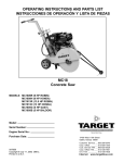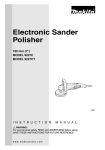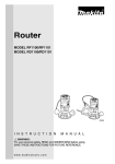
1
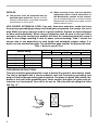
Stone Polisher
MODEL PW5001C
006096
I N S T R U C T I O N
M A N U A L
WARNING:
For your personal safety, READ and UNDERSTAND before using.
SAVE THESE INSTRUCTIONS FOR FUTURE REFERENCE.
w w w. m a k i t a t o o l s. c o m
SPECIFICATIONS
Model
PW5001C
Pad diameter
max. 100mm ( max. 4” )
No load speed (RPM)
2,000 - 4,000/min
Overall length
313 mm (12-3/8”)
Net weight
2.2 kg (4.9 lbs)
• Manufacturer reserves the right to change specifications without notice.
• Specifications may differ from country to country.
GENERAL SAFETY RULES
USA001-3
(For All Tools)
WARNING:
Read and understand all instructions. Failure to follow all
instructions listed below, may result in electric shock, fire and/or
serious personal injury.
SAVE THESE INSTRUCTIONS
Work Area
Electrical Safety
1. Keep your work area clean and well lit.
Cluttered benches and dark areas invite accidents.
4. Grounded tools must be plugged into an
outlet properly installed and grounded in
accordance with all codes and ordinances. Never remove the grounding
prong or modify the plug in any way. Do
not use any adaptor plugs. Check with a
qualified electrician if you are in doubt as
to whether the outlet is properly
grounded. If the tools should electrically malfunction or break down, grounding provides a
low resistance path to carry electricity away
from the user.
2. Do not operate power tools in explosive
atmospheres, such as in the presence of
flammable liquids, gases, or dust. Power
tools create sparks which may ignite the dust
or fumes.
3. Keep bystanders, children, and visitors
away while operating a power tool. Distractions can cause you to lose control.
2
5. Avoid body contact with grounded surfaces such as pipes, radiators, ranges and
refrigerators. There is an increased risk of
electric shock if your body is grounded.
6. Do not expose power tools to rain or wet
conditions. Water entering a power tool will
increase the risk of electric shock.
7. Do not abuse the cord. Never use the cord
to carry the tools or pull the plug from an
outlet. Keep cord away from heat, oil,
sharp edges or moving parts. Replace
damaged cords immediately. Damaged
cords increase the risk of electric shock.
8. When operating a power tool outside, use
an outdoor extension cord marked “W-A”
or “W”. These cords are rated for outdoor
use and reduce the risk of electric shock.
Personal Safety
9. Stay alert, watch what you are doing and
use common sense when operating a
power tool. Do not use tool while tired or
under the influence of drugs, alcohol, or
medication. A moment of inattention while
operating power tools may result in serious
personal injury.
10. Dress properly. Do not wear loose clothing or jewelry. Contain long hair. Keep
your hair, clothing, and gloves away from
moving parts. Loose clothes, jewelry, or
long hair can be caught in moving parts.
11. Avoid accidental starting. Be sure switch
is off before plugging in. Carrying tools with
your finger on the switch or plugging in tools
that have the switch on invites accidents.
12. Remove adjusting keys or wrenches
before turning the tool on. A wrench or a
key that is left attached to a rotating part of
the tool may result in personal injury.
13. Do not overreach. Keep proper footing
and balance at all times. Proper footing and
balance enables better control of the tool in
unexpected situations.
14. Use safety equipment. Always wear eye
protection. Dust mask, non-skid safety
shoes, hard hat, or hearing protection must
be used for appropriate conditions. Ordinary
eye or sun glasses are NOT eye protection.
Tool Use and Care
15. Use clamps or other practical way to
secure and support the workpiece to a
stable platform. Holding the work by hand or
against your body is unstable and may lead
to loss of control.
16. Do not force tool. Use the correct tool for
your application. The correct tool will do the
job better and safer at the rate for which it is
designed.
17. Do not use tool if switch does not turn it
on or off. Any tool that cannot be controlled
with the switch is dangerous and must be
repaired.
18. Disconnect the plug from the power
source before making any adjustments,
changing accessories, or storing the tool.
Such preventive safety measures reduce the
risk of starting the tool accidentally.
19. Store idle tools out of reach of children
and other untrained persons. Tools are
dangerous in the hands of untrained users.
20. Maintain tools with care. Keep cutting
tools sharp and clean. Properly maintained
tools with sharp cutting edges are less likely
to bind and are easier to control.
21. Check for misalignment or binding of
moving parts, breakage of parts, and any
other condition that may affect the tools
operation. If damaged, have the tool serviced before using. Many accidents are
caused by poorly maintained tools.
22. Use only accessories that are recommended by the manufacturer for your
model. Accessories that may be suitable for
one tool, may become hazardous when used
on another tool.
3
SERVICE
23. Tool service must be performed only by
qualified repair personnel. Service or maintenance performed by unqualified personnel
could result in a risk of injury.
24. When servicing a tool, use only identical
replacement parts. Follow instructions in
the Maintenance section of this manual.
Use of unauthorized parts or failure to follow
Maintenance instructions may create a risk of
electric shock or injury.
USE PROPER EXTENSION CORD: Use only three-wire extension cords that have
three-prong grounding-type plugs and three-pole receptacles that accept the tool's
plug. Make sure your extension cord is in good condition. Replace or repair damaged
or worn cord immediately. When using an extension cord, be sure to use one heavy
enough to carry the current your product will draw. An undersized cord will cause a
drop in line voltage resulting in loss of power and overheating. Table 1 shows the
correct size to use depending on cord length and nameplate ampere rating. If in
doubt, use the next heavier gage. The smaller the gage number, the heavier the cord.
Table 1: Minimum gage for cord
Volts
120 V
Ampere Rating
More Than
Not More Than
0
6
10
12
6
10
12
16
25 ft.
Total length of cord in feet
50 ft.
100 ft.
150 ft.
AWG
18
18
16
14
16
16
16
12
16
14
14
12
14
12
Not Recommended
GROUNDING INSTRUCTIONS:
This tool should be grounded while in use to protect the operator from electric shock.
The tool is equipped with a three-conductor cord and three-prong grounding type
plug to fit the proper grounding type receptacle. The green (or green and yellow) conductor in the cord is the grounding wire. Never connect the green (or green and yellow) wire to a live terminal. Your unit is for use on 120 volts and has a plug that looks
like Fig. “A”.
Cover of Grounded
Outlet Box
Grounding
Blade
Fig. A
4
SPECIFIC SAFETY RULES
USB083-2
DO NOT let comfort or familiarity with product (gained from
repeated use) replace strict adherence to stone polisher safety
rules. If you use this tool unsafely or incorrectly, you can suffer
serious personal injury.
1. Accessories must be rated for at least the
speed recommended on the tool warning
label. Wheels and other accessories running
over rated speed can fly apart and cause
injury. Maximum operating speed of accessories should be higher than the highest no load
speed marked on the tool’s nameplate.
2. Hold tool by insulated gripping surfaces
when performing an operation where the
cutting tool may contact hidden wiring or
its own cord. Contact with a “live” wire will
make exposed metal parts of the tool “live”
and shock the operator.
3. Always use safety glasses or goggles.
Ordinary eye or sun glasses are NOT
safety glasses.
4. Check the backing pad carefully for
cracks, damage or deformity before operation. Replace cracked, damaged or
deformed pad immediately.
5. NEVER use tool with wood cutting blades
or other sawblades. Such blades when
used on a stone polisher frequently kick
and cause loss of control leading to personal injury.
6. Hold the tool firmly.
7. Keep hands away from rotating parts.
8. Make sure the abrasive disc is not contacting the workpiece before the switch is
turned on.
9. Do not leave the tool running. Operate the
tool only when hand-held.
11. Check that the workpiece is properly supported.
12. Pay attention that the wheel continues to
rotate after the tool is switched off.
13. For additional protection against electric
shock, be sure to WEAR RUBBER
GLOVES AND RUBBER BOOTS during
operation.
14. When using the water feed, be careful not
to let water get into the motor. If water
runs into the motor, an electric shock hazard may result.
15. Some material contains chemicals which
may be toxic. Take caution to prevent dust
inhalation and skin contact. Follow material supplier safety data.
16. If the plug or receptacle does get wet, DO
NOT unplug the cord. Disconnect the fuse
or circuit breaker that supplies power to
the tool. Then unplug and examine for
presence of water in the receptacle.
17. WARNING: To reduce the risk of electrocution when using an extension cord,
keep ALL connections dry and off the
ground.
18. Ground Fault Circuit Interrupter (GFCI)
protection should be provided on the circuit(s) or outlet(s) to be used for the tool.
Receptacles are available having built-in
GFCI protection and may be used for this
measure of safety.
10. Do not touch the workpiece immediately
after operation; it may be extremely hot
and could burn your skin.
5
SAVE THESE INSTRUCTIONS
WARNING:
MISUSE or failure to follow the safety rules stated in this
instruction manual may cause serious personal injury.
SYMBOLS
USD101-2
The followings show the symbols used for tool.
V ....................... volts
................alternating current
A ....................... amperes
n ....................no load speed
˚
Hz ..................... hertz
.../min................revolutions or reciprocation per
minute
6
FUNCTIONAL
DESCRIPTION
•
004728
CAUTION:
Always be sure that the tool is switched off and
unplugged before adjusting or checking function on the
tool.
Ground Fault Circuit Interrupter
Connect the tool to a power supply and test the Ground Fault
Circuit Interrupter (GFCI) before using the tool. Push the
RESET (R) button and confirm that the pilot lamp lights.
Push the TEST (T) button and confirm that the pilot lamp
goes out. Push the RESET (R) button again to use the tool.
1
2
3
1. Pilot lamp
2. RESET(R)Button
3. TEST(T)Button
•
006097
WARNING:
Do not use the tool if the pilot lamp does not go out when
the TEST (T) button is pushed.
Shaft lock
1
•
CAUTION:
Never actuate the shaft lock when the spindle is moving.
The tool may be damaged.
Press the shaft lock to prevent spindle rotation when installing or removing accessories.
1. Shaft lock
006098
Switch action
•
1
•
1. Slide switch
CAUTION:
Before plugging in the tool, always check to see that the
slide switch actuates properly and returns to the “OFF”
position when the rear of the slide switch is depressed.
Switch can be locked in “ON” position for ease of
operator comfort during extended use. Apply caution
when locking tool in “ON” position and maintain firm
grasp on tool.
To start the tool, slide the slide switch toward the “I (ON)”
position. For continuous operation, press the front of the
slide switch to lock it.
To stop the tool, press the rear of the slide switch, then slide
it toward the “O (OFF)” position.
7
004731
1
1. Speed adjusting dial
Speed adjusting dial
The rotating speed can be changed by turning the speed
adjusting dial to a given number setting from 1 to 5.
Higher speed is obtained when the dial is turned in the direction of number 5. And lower speed is obtained when it is
turned in the direction of number 1.
Refer to the below table for the relationship between the
number settings on the dial and the approximate rotating
speed.
C00098
•
•
Number
RPM(/min)
1
2,000
2
2,500
3
3,000
4
3,500
5
4,000
CAUTION:
If the tool is operated continuously at low speeds for a
long time, the motor will get overloaded and heated up.
The speed adjusting dial can be turned only as far as 5
and back to 1. Do not force it past 5 or 1, or the speed
adjusting function may no longer work.
Electronic function
Constant speed control
Possible to get fine finish, because the rotating speed is kept
constant even under the loaded condition.
Additionaly, when the load on the tool exceeds admissible
levels, power to the motor is reduced to protect the motor
from overheating. When the load returns to admisible levels,
the tool will operate as normal.
Soft start feature
Soft start because of suppressed starting shock.
8
004732
To keep the lever on the tool for water flow open, turn it to the
position A where the water passage will be ready. Return it to
the position B to close.
3
B
2
Opening or closing of water lever
A
1
1. Lever
2. Open
3. Close
ASSEMBLY
•
006099
Installing side grip (handle)
•
005588
1
CAUTION:
Always be sure that the tool is switched off and
unplugged before carrying out any work on the tool.
CAUTION:
Always be sure that the side grip is installed securely
before operation.
Screw the side grip securely on the position of the tool as
shown in the figure.
Remove one of the screws which secure gear housing and
head cover then screw the side grip on the tool.
2
3
1. Head cover
2. Side grip
3. Screw
9
005586
Installing or removing the front grip
1
•
2
•
1. Head cover
2. Screw
CAUTION:
Make sure that the front grip is installed securely before
operation.
The front grip and the side grip cannot be installed at the
same time.
Remove two screws and then the head cover.(The front grip
cannot be installed during the installation of head cover on
the tool.)
005587
1
3
2
4
Install the front grip on the tool so that its stopper fits to the
gear housing and tighten the two screws as shown in the figure. (The front grip and the side grip cannot be installed at
the same time.)
5
1.
2.
3.
4.
5.
Gear housing
Stopper
Front grip
Flat washer
Hex socket head bolt
006100
1
2
Installing or removing abrasive disc
(Optional accessory)
Remove all dirt or foreign matter from the pad.
Screw the pad onto the spindle with pressing the shaft lock.
Attach the disc to the pad so carefully that the edges of disc
and pad overlap each other without protruding.
3
1. Abrasive disc
2. Pad
3. Spindle
006101
10
To remove the abrasive disc, pull off its edge from the pad.
004736
2
1
Hose connector assembly
Use the hose connector assembly to connect to water
source. It consists of the following parts.
3
4
C00099
Part name
2
1.
2.
3.
4.
Water cock
Hose connector
Connector
Hose
Description
Hose Connecter
1/2” pipe thread
Connecter
1/2”mail pipe thread
Hose
5/8”in inner diameter × 25’ in length
Assemble the above parts hand tight as follows.
1. Attach the hose connector to the outlet of water cock.
2. Tighten the connector firmly to the hose. Insert the connector to the hose connector as far as it will go.
3. Tighten the hose connector to the end of the hose.
4. Fit the hose connector to the port on the tool.
OPERATION
006102
Polishing operation
•
006103
•
WARNING:
To reduce the risk of electric shock, check the tool's
water supply system to ensure there is no damage to the
seals (“O” rings) or hoses. A damaged water supply
system may result in abnormal water flow to the tool
which could be dangerous.
CAUTION:
Always wear safety goggles or a face shield during
operation.
•
Never switch on the tool when it is in contact with the
workpiece, it may cause an injury to operator.
•
Never run the tool without the abrasive disc. You may
seriously damage the pad.
Make sure that the cock is closed. Connect the hose to the
tool. Make sure that water comes out when the water lever is
opened.
Hold the tool firmly. Turn the tool on and then apply the abrasive disc to the workpiece.
Apply slight pressure only. Excessive pressure will result in
poor performance and premature wear to abrasive disc.
11
MAINTENANCE
006104
1
•
2
1. Exhaust vent
2. Inhalation vent
006105
CAUTION:
Always be sure that the tool is switched off and
unplugged before attempting to perform inspection or
maintenance.
The tool and its air vents have to be kept clean. Regularly
clean the tool’s air vents or whenever the vents start to
become obstructed.
Replacing dust cover brush
Replace the brush on the dust cover shortly after its tip is
damaged. To replace the brush, slide it in the direction of
arrow as shown in the figure.
The dust cover is used to reduce the risk of dust intrusion
into tool body. Be sure to use the tool with the dust cover in
place when operating. Should it be damaged, replace it with
new one without fail.
Long use and operation of the tool using much water causes
buildup of dust inside the tool. To maintain the product safety
and operate the tool with high efficiency, always check the
exhaust vent at the back of tool.
When you find buildup of dust in that area, ask Makita service center for cleaning inside of the tool. Never disassemble
or clean the inside of the tool by yourself. Early request for
cleaning is recommended at all times.
To maintain product SAFETY and RELIABILITY, repairs, carbon brush inspection and replacement, any other maintenance or adjustment should be performed by Makita
Authorized or Factory Service Centers, always using Makita
replacement parts.
12
ACCESSORIES
•
CAUTION:
These accessories or attachments are recommended for
use with your Makita tool specified in this manual. The
use of any other accessories or attachments might
present a risk of injury to persons. Only use accessory
or attachment for its stated purpose.
If you need any assistance for more details regarding these
accessories, ask your local Makita service center.
•
Abrasive discs
•
Side grip
•
Front grip
•
Rubber pad
13
Memo
14
Memo
15
Memo
16
Cut
First-Class
Postage
Required
Post Office will
not deliver
without proper
postage.
Makita U.S.A., Inc.
14930 Northam Street
La Mirada, CA 90638-5753
Fold
17
MAIL THIS PORTION
Your answers to the following questions are appreciated.
1. This product was purchased from:
3. How did you learn about this product:
Other (
Magazine
Radio
Hardware/Lumber Store
From Dealer
Exhibition
Tool Distributor
Newspaper
From Friend
Industrial Supply
Store Display
Previous Usage
Construction Supply
Catalog
Other (
Home Center
)
2. Use of the product is intended for:
)
4. Most favored points are:
Construction Trade
Design
Repair Service
Industrial Maintenance
Features
Durability
Home Maintenance
Size
Power
Hobby
Price
Other (
Other (
)
)
Makita Brand
5. Any comments:
Paste
MODEL NO.
DAY
YEAR
SERIAL NO.
SEX
STATUS
INTL.
LAST NAME / COMPANY NAME
Married Single
M
F
STREET ADRESS
Paste
MONTH
Paste
Paste
Paste
Paste
DATE PURCHASED
Under 19
AREA
CODE
PHONE
20-29
30-39
Paste
AGE:
ZIP CODE
40-49
50-60
Over 60
Paste
Paste
STATE
Paste
CITY
Paste
Paste
BE SURE TO COMPLETE THE CUSTOMER’S PORTION OF THIS FORM AND RETAIN FOR YOUR RECORDS.
Please return this portion by facsimile or mail.
18
Facsimile No: (714) 522-8133
Paste
Paste
Paste
Paste
Paste
Paste
Paste
Paste
FACTORY SERVICE CENTERS
1-800-4-MAKITA
RETAIN THIS PORTION FOR YOUR RECORDS
ARIZONA
3707 E. Broadway Rd., Ste. 6
Phoenix, AZ 85040
(602) 437-2850
FLORIDA
750 East Sample Road
Pompano Beach, FL 33064
(954) 781-6333
MISSOURI
9876 Watson Road
St. Louis, MO 63126-2221
(314) 909-9889
PENNSYLVANIA
1904 Babcock Boulevard
Pittsburgh, PA 15209
(412) 822-7370
CALIFORNIA
41850 Christy Street
Fremont, CA 94538-5107
(510) 657-9881
GEORGIA
4680 River Green Parkway NW
Duluth, GA 30096
(770) 476-8911
NEBRASKA
4129 S. 84th Street
Omaha, NE 68127
(402) 597-2925
PUERTO RICO
200 Guayama Street
Hato Rey, PR 00917
(787) 250-8776
ILLINOIS
1450 Feehanville Dr.
Mt. Prospect, IL 60056-6011
(847) 297-3100
NEVADA
3375 S. Decatur Blvd.
Suites. 22 - 24
Las Vegas, NV 89102
(702) 368-4277
TENNESSEE
1120 Elm Hill Pike Suite 170
Nashville, TN 37210
(615) 248-3321
14930 Northam Street
La Mirada, CA 90638-5753
(714) 522-8088
4191A Power Inn Rd.
Sacramento, CA 95826
(916) 454-4768
7674 Clairemont Mesa Blvd.
San Diego, CA 92111
(858) 278-4471
16735 Saticoy St., Ste. 105
Van Nuys, CA 91406
(818) 782-2440
COLORADO
11809 E. 51st Ave.
Denver, CO 80239-2709
(303) 371-2850
MARYLAND
7397 Washington Blvd Ste 104
Elkridge, MD 21075
(410) 796-4401
MASSACHUSETTS
232 Providence Highway
Westwood, MA 02090
(781) 461-9754
MINNESOTA
6427 Penn Ave. South
Richfield, MN 55423
(612) 869-5199
NEW JERSEY
251 Herrod Blvd.
Dayton, NJ 08810-1539
(609) 655-1212
NEW YORK
4917 Genessee Street
Cheektowaga, NY 14225
(716) 685-9503
OREGON
828 19th Ave., N.W.
Portland, OR 97209
(503) 222-1823
TEXAS
12801 Stemmons Fwy. Ste. 809
Farmers Branch, TX 75234
(972) 243-1150
4321 W. Sam Houston Pkwy
Suite 130
Houston, TX 77043
(713)983-8034
3453 IH-35 North, Ste. 101
San Antonio, TX 78219
(210) 228-0676
WISCONSIN
Lincoln Plaza Shopping Ctr.
2245 S. 108th Street
West Allis, WI 53227
(414) 541-4776
CUSTOMER’S RECORD
When you need service: Send
complete tool (prepaid) to one
of the Makita Factory Service
Centers listed, or to an Authorized
Makita Service Center. Be sure
to attach a letter to the outside of
the carton detailing the problem
with your tool.
Date Purchased
Dealer’s Name & Address
Model No.
Serial No.
19
WARNING
Some dust created by power sanding, sawing, grinding, drilling, and other
construction activities contains chemicals known to the State of California
to cause cancer, birth defects or other reproductive harm. Some examples
of these chemicals are:
• lead from lead-based paints,
• crystalline silica from bricks and cement and other masonry products, and
• arsenic and chromium from chemically-treated lumber.
Your risk from these exposures varies, depending on how often you do this
type of work. To reduce your exposure to these chemicals: work in a well
ventilated area, and work with approved safety equipment, such as those
dust masks that are specially designed to filter out microscopic particles.
MAKITA LIMITED ONE YEAR WARRANTY
Warranty Policy
Every Makita tool is thoroughly inspected and tested before leaving the factory. It is warranted to be free of
defects from workmanship and materials for the period of ONE YEAR from the date of original purchase.
Should any trouble develop during this one year period, return the COMPLETE tool, freight prepaid, to one of
Makita’s Factory or Authorized Service Centers. If inspection shows the trouble is caused by defective
workmanship or material, Makita will repair (or at our option, replace) without charge.
This Warranty does not apply where:
• repairs have been made or attempted by others:
• repairs are required because of normal wear and tear:
• the tool has been abused, misused or improperly maintained:
• alterations have been made to the tool.
IN NO EVENT SHALL MAKITA BE LIABLE FOR ANY INDIRECT, INCIDENTAL OR CONSEQUENTIAL
DAMAGES FROM THE SALE OR USE OF THE PRODUCT. THIS DISCLAIMER APPLIES BOTH DURING
AND AFTER THE TERM OF THIS WARRANTY.
MAKITA DISCLAIMS LIABILITY FOR ANY IMPLIED WARRANTIES, INCLUDING IMPLIED WARRANTIES OF
“MERCHANTABILITY” AND “FITNESS FOR A SPECIFIC PURPOSE,” AFTER THE ONE YEAR TERM OF THIS
WARRANTY.
This Warranty gives you specific legal rights, and you may also have other rights which vary from state to state.
Some states do not allow the exclusion or limitation of incidental or consequential damages, so the above
limitation or exclusion may not apply to you. Some states do not allow limitation on how long an implied
warranty lasts, so the above limitation may not apply to you.
Makita Corporation
3-11-8, Sumiyoshi-cho,
Anjo, Aichi 446-8502 Japan
884519D067