1
JAROL Assumes the promotion of energy-saving technology as its own task!
1. PREFACE
Thanks for choosing JR6000 series frequency inverter!
This manual introduces how to use the JR6000 frequency inverter correct.Before you use the
frequency inverter , please read this manual carefully and know the safety precautions
clearly
NOTICE
·
In order to explain the detailed things , some of the pictures are the frequency
inverter remove the shape.when you use the frequency inverter, please close and
install the coverings,follow the manual to operate.
·
Some of the pictures in this manual just for explain,maybe different from your order
sample.
·
If you have any other questions you can contact with our company
1
JiaXing Jarol Scientific Instrument Co.,Ltd-JR6000 series products
CONTENTS
....................................................................................................................................... 1
1. PREFACE
PREFACE.......................................................................................................................................
.........................................................................................................................................
2
CONTENTS
CONTENTS.........................................................................................................................................
.........................................................................................................................................2
..................................................................................................... 11
2. PRODUCT INFORMATION
INFORMATION.....................................................................................................
2.1 NAMING RULE....................................................................................................................... 11
2.2NAMEPLATE............................................................................................................................12
2.3 FREQUENCY INVERTER SERIES TYPE................................................................................... 12
2.4 TECHNICAL SPECIFICATION.................................................................................................. 13
2.5 PARTS DESCRIPTION............................................................................................................ 15
3.
.......................................................................................................................
16
INSTALLATION
INSTALLATION.......................................................................................................................
.......................................................................................................................16
3.1 INSTALL ENVIRONMENT........................................................................................................ 16
3.2 HOW TO INSTALL................................................................................................................. 16
3.3 MORE THAN TWO INVERTERS INSTALL................................................................................. 17
3.4 EXTERNAL DIEMENSION OF FREQUENCY INVERTER............................................................ 17
3.5 KEYBOARD DIMENSION OF INVERTER.................................................................................19
.......................................................................................................................................... 20
4.WIRING
4.WIRING..........................................................................................................................................
4.1 CONNECTION OF PERIPHERAL DEVICES.............................................................................. 21
4.2 TERMINAL CONFIGURATION.................................................................................................. 22
4.3WIRINGCONTROLCIRCUIT TERMINAL CONNECT................................................................... 27
4.4 INSTALLATION GUIDLINE TO EMC COMPLIANCE.................................................................. 34
......................................................................... 39
5.OPERATION KEYBOARD AND OPERATION
OPERATION.........................................................................
2
JAROL Assumes the promotion of energy-saving technology as its own task!
5.1 KEYPAD DESCRIPTION......................................................................................................... 39
5.2 OPERATION PROCESS.......................................................................................................... 43
5.3 RUNNING STATE................................................................................................................... 45
5.4 SHORTCUT MENU................................................................................................................. 46
.................................................................................... 47
6.DETAILED FUNCTION DESCRIPTION
DESCRIPTION....................................................................................
F0 GROUP BASIC FUNCTION......................................................................................................47
F1 GROUP START AND STOP CONTROL.................................................................................... 55
F2 GROUP MOTOR PARAMETERS.............................................................................................. 60
F3 GROUP VECTOR CONTROL................................................................................................... 61
F4 GROUP V/F CONTROL.......................................................................................................... 64
F5 GROUP INPUT TERMINALS.................................................................................................... 67
F6 GROUP OUTPUT TERMINALS................................................................................................ 73
F7 GROUP DISPLAY INTERFACE................................................................................................. 76
F8GROUP ENHANCED FUNCTION...............................................................................................82
F9 GROUP PID CONTROL.......................................................................................................... 88
FA GROUP SIMPLE PLC AND MULTI-STEP SPEED CONTROL....................................................92
FB GROUP PROTECTION FUNCTION...........................................................................................97
FCGROUPSERIALCOMMUNICATION..........................................................................................102
FD GROUP SUPPLEMENTARY FUNCTION..................................................................................105
FE GROUP FACTORY SETTING.................................................................................................105
.............................................................................................
106
7. COMMUNICATION PROTOCOL
PROTOCOL.............................................................................................
.............................................................................................106
7.1 INTERFACES........................................................................................................................106
3
JiaXing Jarol Scientific Instrument Co.,Ltd-JR6000 series products
7.2 COMMUNICATION MODES................................................................................................... 106
7.3 PROTOCOL FORMAT........................................................................................................... 106
7.4 PROTOCOL FUNCTION........................................................................................................ 107
7.5 NOTE:................................................................................................................................. 114
7.6 CRC CHECK.......................................................................................................................115
7.7 EXAMPLE.............................................................................................................................116
.............................................................................................................
119
8. TROUBLE SHOOTING
SHOOTING.............................................................................................................
.............................................................................................................119
8.1 FAULT AND TROUBLE SHOOTING........................................................................................ 119
8.2 COMMON FAULTS AND SOLUTIONS.................................................................................... 125
9. MAINTENANCE
.........................................................................................................................
127
MAINTENANCE.........................................................................................................................
.........................................................................................................................127
9.1 DAILY MAINTENANCE..........................................................................................................127
9.2 PERIODIC MAINTENANCE................................................................................................... 128
9.3 REPLACEMENT OF WEARING PARTS................................................................................... 128
9.4 GUARANTEE....................................................................................................................... 129
.................
129
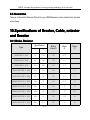
10.SPECIFICATIONS OF BREAKER, CABLE, CONTACTOR AND REACTOR
REACTOR.................
.................129
10.1 BRAKE RESISTOR............................................................................................................ 129
10.2 SPECIFICATIONS OF BREAKER, CABLE, CONTACTOR AND REACTOR.............................. 130
10.3 SPECIFICATIONS OF INPUT/OUTPUT AC REACTOR AND DC REACTOR........................... 131
................................................................................... 132
11. LIST OF FUNCTION PARAMETERS
PARAMETERS...................................................................................
4
JAROL Assumes the promotion of energy-saving technology as its own task!
1. SAFETY PRECAUTIONS
WARNING:Points
out potential danger which, if not avoided, may cause
physical injury or death.
Points out potential danger which, if not avoided, may
! CAUTION
CAUTION::
result in mild or moderate physical injury and damage to
the equipment. It’s also available to warns about unsafe
operations.
In some cases, even the content described in “Note” may also cause serious accidents. So
please follow these important precautions in any situations.
1.1.1
Safety attentions
Before install
1.1.2
1.1.2B
install:
Danger
·
·
·
·
parts lost or parts damage,don
Open the shape find the control system in water
water、parts
damage,don’’t install!
don
if the product different from the packing list
list!don
don’’t install!
Carefully handled when loading, otherwise it may damage the inverter!
Do not use the damaged inverter or inverter with missing parts. Otherwise, there may be risk of
injury.
· Do not touch the control system, otherwise it will cause static electricity!
When install
1.1.3
1.1.3W
install:
Danger
· install the inverter on incombustible surface like metal, and keep away from
fammable substances. Otherwise it may cause fire.
5
JiaXing Jarol Scientific Instrument Co.,Ltd-JR6000 series products
st the set screw of the equitment, especially the screws marked in RED.
· Do not lo
lost
Caution
·Do not drop the lead wire stub or screw in the inverter. Otherwise it may damage the inverter!
·Please install the driver in the place where there is no direct sunlight and no shock!
· When more than two inverters are to be installed in one cabinet, due attention shall be paid to
the installation locations (refer to Chapter 3 Mechanical and
Electrical Installation) to ensure the heat sinking effec
effectt!
Wiring
1.1.4
1.1.4Wiring
Wiring:
Danger
· Operation shall be performed by the professional engineering technician. Otherwise there will
be danger of electric shock
shock!
· There shall be circuit breaker between the inverter and power supply. Otherwise, there may be
fire
re!
· Make sure the power is disconnected prior to the connection. Otherwise there will be danger of
electric shock
shock!
The earth terminal shall be earthed reliably. Otherwise there may be danger of electric shock
·The
shock!
Danger
V、W
W。Don
Don
· Prohibit the input power connect with the output terminals U、V
Don’’t connect the wrong
way about the wiring,pls check the terminals carefully!
·Make sure all the wiring according with the EMC and the stay area
area’’s safe standard All the cables
must use as manual
manual’’s reference
reference!
+)、
other wire it may cause fire
· Don
Don’’t connect the brake resistor between DC bus (+
(--)
,other
fire!
6
JAROL Assumes the promotion of energy-saving technology as its own task!
1.1.5
Upon Power-on
1.1.5Upon
Power-on:
Caution
· At power-on, the inverter will perform the security check of the external
heavy-current circuit automatically. Thus, at this time please do not touch
the terminals U, V and W, or the terminals of motor, otherwise there will be
danger of electric shock!
· The inverter is free from dielectric test because this test is performed prior to the delivery.
Otherwise accident may occur!
Danger
· must close the frequency inverter shape then power on,other wise electric shock occur!
· All the cables must use as manual
manual’’s reference ,according with the manual
manual’’s connect diagram
diagram,
otherwise accident occur!
After Power-on
1.1.6
1.1.6After
Power-on:
Danger
· Do not open the cover of the inverter upon power-on. Otherwise there will be danger of electric
shock
shock!
· Do not touch the inverter and its surrounding circuit with wet hand. Otherwise there will be
danger of electric shock
shock!
· Do not touch the inverter terminals (including control terminal). Otherwise there will be danger
of electric shock
shock!
· At power-on, the inverter will perform the security check of the external heavy-current circuit
automatically. Thus, at this time please do not touch
the terminals U, V and W, or the terminals of motor, otherwise there will be danger of electric
shock!
7
JiaXing Jarol Scientific Instrument Co.,Ltd-JR6000 series products
Danger
· If parameter identification is required, due attention shall be paid to the danger of
injury
arising from the rotating motor. Otherwise accident may occur
occur!
· Do not change the factory settings at will. Otherwise it may damage the equipment!
In Service
1.1.7
1.1.7In
Service:
Danger
·Do not touch the fan or discharge resistor to sense the temperature.
Otherwise, you may get burnt
burnt!
·Detection of signals during the operation shall only be conducted by qualifed technician.
Otherwise, personal injury or equipment damage may
be caused!
Caution
· During the operation of the inverter, keep items from falling into the equipment. Otherwise, it
·
may damage the equipment
equipment!
During the operation of the inverter, keep items from falling into the equipment. Otherwise, it
may damage the equipment!
Maintenance
1.1.8
1.1.8Maintenance
Maintenance:
Danger
· Do not repair and maintain the equipment with power connection. Otherwise
8
JAROL Assumes the promotion of energy-saving technology as its own task!
there will be danger of electric shock!
· be sure to conduct repair and maintenance after the charge LED indictor of the inverter is OFF.
Otherwise, the residual charge on the capacitor may cause personal injury!
· The inverter shall be repaired and maintained only by the qualifed person who has received
professional training. Otherwise, it may cause personal injury or equipment damage!
· Carry out parameter setting after replacing the inverter, all the plug-ins must
be plug and play when power outage!
1.2 Precautions
1.2.1 Motor Insulation Inspection
When the motor is used for the first time, or when the motor is reused after being kept, or when
periodical inspection is performed, it shall conduct motor insulation inspection so as to avoid damaging
the inverter because of the insulation failure of the motor windings. The motor wires must be
disconnected from the inverter during the insulation inspection. It is recommended to use the 500V
megameter, and the insulating resistance measured shall be at least 5MΩ。
1.2.2 Thermal Protection of the Motor
If the ratings of the motor does not match those of the inverter, especially when the rated,please
adjust some parameters let the KW suitable for the motor.
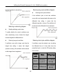
1.2.3 Running with Frequency higher than Standard Frequency
This inverter can provide output frequency of 0Hz to 400Hz. If the user needs to run the inverter with
frequency of more than 50Hz, please take the resistant pressure of the mechanical devices.
1.2.4 Vibration of Mechanical Device
The inverter may encounter the mechanical resonance point at certain output
can be avoided by setting the skip frequency parameters in the inverter.
frequencies, which
1.2.5 Motor Heat and Noise
Since the output voltage of inverter is PWM wave and contains certain harmonics, the temperature
rise, noise and vibration of the motor will be higher than those when it runs at standard frequency。
1.2.6 Voltage-sensitive Device or Capacitor Improving Power Factor at the Output
Side
Since the inverter output is PWM wave, if the capacitor for improving the power factor or
voltage-sensitive resistor for lightning protection is mounted at the output side, it is easy
to cause instantaneous over current in the inverter, which may damage the inverter. It is
recommended that such devices not be used.
1.2.7 Switching Devices like Contactors Used at the Input and Output terminal
If a contactor is installed between the power supply and the input terminal of the inverter, it is not
allowed to use the contactor to control the startup/stop of the inverter. If use of such contactor is
unavoidable, it shall be used with interval of at least one hour.
Frequent charge and discharge will
reduce the service life of the capacitor inside the inverter. If switching devices like contactor are installed
between the output end of the inverter and the motor, it shall ensure that the on/off operation is conducted
9
JiaXing Jarol Scientific Instrument Co.,Ltd-JR6000 series products
when the
inverter has no output. Otherwise the modules in the inverter may be damaged.
1.2.8 Use under voltage rather than rated voltage
If the series inverter is used outside the allowable working voltage range as specifed in this manual, it
is easy to damage the devices in the inverter. When necessary, use the corresponding step-up or
step-down instruments to change the voltage.
1.2.9 Change Three-phase Input to Two-phase Input
It is not allowed to change the JR6000 series three-phase inverter into two-phase one.
may cause fault or damage to the inverter.
Otherwise, it
1.2.10 Lightning shock protection
The series inverter has lightning over current protection device, and has certain self-protection
capacity against the lightning. In applications where lightning occurs fre quently, the user shall
install additional protection devices at the front-end of the inverter.
1.2.11 Altitude and Derating
In areas with altitude of more than 1,000 meters, the heat sinking effect of the inverter may
turn poorer due to rare air. Therefore, it needs to derate the inverter for use. Please contact our
company for technical consulting in case of such condition.
1.2.12 Special Use
If the user needs to use the inverter with the methods other than the recommended wiring diagram in
this manual, such as shared DC bus, please consult our company.
1.2.13 Note of Inverter Disposal
The electrolytic capacitors on the main circuit and the PCB may explode when they are burnt.
Emission of toxic gas may be generated when the plastic parts are burnt. Please dispose the inverter as
industrial wastes.
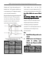
1.2.14 Adaptable Motor
1) The standard adaptable motor is four-pole squirrel-cage asynchronous induction motor. If
such motor is not available, be sure to select adaptable motors in according to the rated
current of the motor. In applications where drive permanent magnetic synchronous motor is
required, please consult our company;
2) The cooling fan and the rotor shaft of he non-variable-frequency motor adopt coaxial
connection. When the rotating speed is reduced, the cooling effect will be poorer. Therefore, a
powerful exhaust fan shall be installed, or the motor shall be replaced with variable-frequency
motor to avoid the over heat of the motor.
3) Since the inverter has built-in standard parameters of the adaptable motors, it is necessary
to perform motor parameter identification or modify the default values so as to comply with
the actual values as much as possible, or it may affect the running effect and protection
performance;
4)The short circuit of the cable or motor may cause alarm or explosion of the inverter.
Therefore, please conduct insulation and short circuit test on the newly installed motor and
cable. Such test shall also be conducted during routine maintenance. Please note that the
inverter and the test part shall be completely disconnected during the test.
10
JAROL Assumes the promotion of energy-saving technology as its own task!
2.
PRODUCT INFORMATION
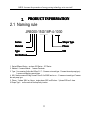
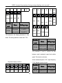
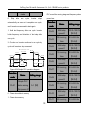
2.1 Naming rule
JR6000-15G/18P-4-1030
Series
Shape Type
Material
Phase
Type
KW
Not Defined
1. Series:Different Series,we have JR6 Series、JR7 Series
2. Material:0 means Module、1 means Transistor
3. Type:0 no meaning (follow the KW as G、P,G means universal type,P means fan and pump type)、
1 means woodworking special type
4. KW:Number means KW big or small,from 0.4 to 55KW and so on ,G means universal type P means
fan and pump type
5. Phase:3 phase 380V as 4 show、single phase 220V as S2 show、3 phase 220V as 2 show
6. Shape Type ::as the mode of the frequency inverter
11
JiaXing Jarol Scientific Instrument Co.,Ltd-JR6000 series products
2.2Nameplate
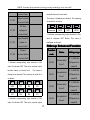
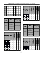
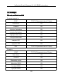
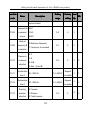
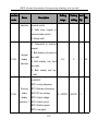
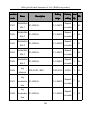
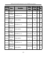
2.3 Frequency inverter series type
Type
Input V
JR6000-0R7G-4-1010
Rated
output
KW
(KW
KW)
Rated
input
current
A)
(A
Rated
output
current
A)
(A
Motor
KW
(KW
KW)
0.75
3.4
2.5
0.75
1.5
5.0
3.7
1.5
2.2
5.8
5
2.2
4.0/5.5
10/15
9/13
4.0/5.5
3 Phase
JR6000-1R5G-4-1010
JR6000-2R2G-4-1010
JR6000-004G/5R5P-4-1020
380V
Range:
-15%
12
JAROL Assumes the promotion of energy-saving technology as its own task!
~+15%
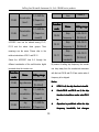
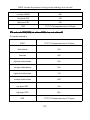
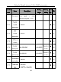
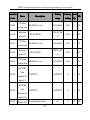
JR6000-5R5G/7R5P-4-1020
5.5/7.5
15/20
13/17
5.5/7.5
JR6000-7R5G/011P-4-1020
7.5/11.0
20/26
17/25
7.5/11.0
JR6000-011G/015P-4-1030
11.0/15.0
26/35
25/32
11.0/15.0
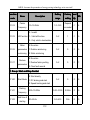
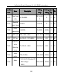
15.0/18.5
35/38
32/37
15.0/18.5
18.5/22.0
38/46
37/45
18.5/22.0
22.0/30.0
46/62
45/60
22.0/30.0
30.0/37.0
62/76
60/75
30.0/37.0
JR6000-037G/045P-4-1050
37.0/45.0
76/90
75/90
37.0/45.0
JR6000-045G/055P-4-1050
45.0/55.0
90/105
90/110
45.0/55.0
JR6000-055G/075P-4-1050
55.0/75.0
105/140
110/150
55.0/75.0
JR6000-015G/018P-4-1030
JR6000-018G/022P-4-1040
3 Phase
380V
JR6000-022G/030P-4-1040
JR6000-030G/037P-4-1040
Range:
-15%
~+15%
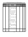
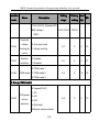
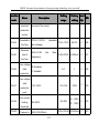
2.4 Technical Specification
Function description
Specification indexes
Control nature
Control mode
Control Without PG Vector、V/F Control、Torque control
Start torque
0.5Hz 150%(SVC)
1.0Hz 150%(V/F)
Speed adjustable
range
Stable speed
precision
1:100(SVC)
±0.5%Max speed(SVC)
13
JiaXing Jarol Scientific Instrument Co.,Ltd-JR6000 series products
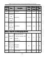
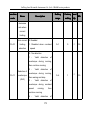
Important function
Product functions
Frequency given
way
Frequency Range
Multifunctions
shortcut key
0.1-3600.0s
Special function
DC braking start frequency:0.00-400.00Hz;DC braking current:
0.0-150%;DC braking time:0.0-50.0s;Noneed for DC braking
start waitting time,realize quickly braking
Multifunctions shortcutkey can be seted for these operation:JOG
inching、REV and FWD、Clear UP/DOWN set、left shift key
display the status、Quickly debug mode
Multi menu mode
Basic menu mode、Fast menu mode
Common DC bus
Many frequency inverters Common DC bus,Energy automatic
equilibrium
Swing frequency
control
Multi pyramidal wave frequency control
Counting control
Counting function
Overcurrent、Overvoltage、Undervolage、Over temp、Phase lack、Overload
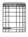
Operation Place
Environment
0.00-400.00Hz
Acc and Dec time
Dynamic braking
Protection
function
RPM track、Torque limitation、Multi-step speed、automatic
self-adjustment、Slip compensate、PID adjust、Sagged control、
Current control、Torque boost、Multifunctions input /output
terminal
Keyboard、upper computer、Analog AI1/AI2、Terminal pulse HDI、
Multi-step speed and PLC、PID, The combination of multi-modes
and the switch between different modes can be realized.
Indoor,hide sunshine,No dust、Corrosive gas、combustible gas、
Oil mist、Water vapor、salinity
Altitude
<1000m
Temperature
-10℃~+40℃(temperature at 40℃~50℃,Drop the forehead
use)
Humidity
<95%RH,No droplet
Vibration
<5.9m/s2(0.6g)
Stock
-20℃~+60℃
14
JAROL Assumes the promotion of energy-saving technology as its own task!
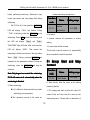
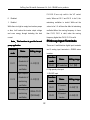
2.5 Parts Description
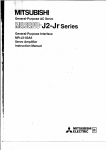
1、0.4KW-15KW Plastic shape description
Picture 2-1 0.4KW-15Kw part’s name
15
JiaXing Jarol Scientific Instrument Co.,Ltd-JR6000 series products
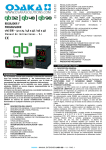
Picture 2-2 18.5KW-55Kw part’s name
3.
INSTALLATION
3.1 Install Environment
1、Temperature:-10℃~+50℃, if the temperature is above 40℃,please put your inverter in place well
inventilized.
2、Humidity: 0%~95% without dew.
3、Away from corrosive gas ,liquid,oil mist or salt mist.
4、No dust or metal powder or debris.
5、No viberation and machinery shock.
6、No electromagnetion noise(such as welding machine).
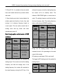
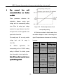
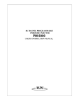
3.2 How To Install
For better cooling down the inverter, it is recommended to install the inverter vertically. There are force
cooling fan on the bottom of the inverter, enough space must be guaranteed between these cooling fans
16
JAROL Assumes the promotion of energy-saving technology as its own task!
and its adjacent objects in all directions.
Figure 3-1 Installtion Distance
3.3 More than two inverters install
If two inverters installed one onto the other,a guide plate is necessary
Figure 3-2 Install More Than two Inverters
3.4 External Diemension of frequency inverter
17
JiaXing Jarol Scientific Instrument Co.,Ltd-JR6000 series products
Figure 3-4
1.5KW-15KW External Diemensions
Figure 3-5
18.5KW-55KW External Diemensions
NOTE:Install 18.5KW to 55KW,pick off the keyboard first then move the cover plate!!
External Diemension and Installation Diemension
kW
(kW
kW)
A
B
H
W
D
mm
(mm
mm)
mm
(mm
mm)
mm
(mm
mm)
mm
(mm
mm)
mm
(mm
mm)
Installation
External Diemension
18
Hole
mm
(mm
mm)
JAROL Assumes the promotion of energy-saving technology as its own task!
Diemension
0.75~2.2
113.5
161.5
170
125
149
5
4~7.5
132
204
220.5
150
174
7
11~15
115
436.5
453
153
218.2
6
18.5~30
176
454.5
467
290
215
6.5
37~55
230
564.5
577
375
270
7
3.5 Keyboard Dimension Of Inverter
3-6 External Keyboard’s Dimension
3-7 External Keyboard’s open pore Dimension
19
JiaXing Jarol Scientific Instrument Co.,Ltd-JR6000 series products
4.WIRING
Warning
20
JAROL Assumes the promotion of energy-saving technology as its own task!
●Only qualified electricians are allowed to operate on the safe running of the iverter.
●Never carry out any insulation or voltage withstand tests on the cables connecting with the inverter.
●Even if the inverter is stopped, dangerous voltage is present at the input power lines, DC circuit
terminals and motor terminals. Wait for 10 minutes even when the inverter is switched off until is
discharge the CHARGE light is off before operation.
●Ground the grounding terminals of the inverter with proper techniques. And the resistor should be less
than 10Ω. Otherwise there is danger of electrical shock and fire.
●Do not connect 3-phase power supply to the output terminals (U, V, W)of the inverter, otherwise damage
to the inverter may occur.
●Please ensure the right connection between the power supply wires and motor wires. Connect the
power supply to the R, S and T terminalds and connect motor wires to U, V and W terminals.
●Never do wiring or other operations on the servo drive with wet hands. Otherwise there is danger of
electric shock.
Caution
●Verify that the rated voltage of the inverter equals to the voltage of the AC power supply.
●The power wires and motor wires must be permanently fastened and connected.
4.1 Connection of Peripheral Devices
21
JiaXing Jarol Scientific Instrument Co.,Ltd-JR6000 series products
Figure 4.1 Connection of peripheral devices.
22
JAROL Assumes the promotion of energy-saving technology as its own task!
4.2 Terminal Configuration
4.2.1 Main Circuit Terminals(AC 380V)
Figure 4-2 Main Circuit Terminals(0.75KW~2.2KW)
Figure 4-3 Main Circuit Terminals(4.0KW~7.5KW)
Figure 4-4 Main Circuit Terminals(11KW~15KW)
Figure 4-5 Main Circuit Terminals(18.5KW~30KW)
Figure 4-6 Main Circuit Terminals(37KW~55KW)
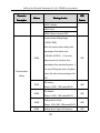
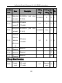
4.2.2 The function of main circuit terminals are described as followings:
23
JiaXing Jarol Scientific Instrument Co.,Ltd-JR6000 series products
Terminal Symbol
R、S、T
Function Description
Terminals of 3 phase AC input
Spare terminals of external braking unit ( 380V up
(+)、(-)
18.5kW)
Spare terminals of external braking resistor,380V down
(+)、PR
15kW
P1、(+)
Spare terminals of external DC reactor
U、V、W
Terminals of 3 phase AC output
Terminal of ground
4.2.3 Main Circuit Standard Connect
0.75-15KW
18.5-55KW
Figure 4-7 Main Circuit Standard Connect
24
JAROL Assumes the promotion of energy-saving technology as its own task!
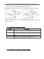
4.2.4 Wiring at input side of main
circuit
when fault occurs to the system, it is necessary
to install a contactor at the input side to control
Circuit breaker
the ON-OFF of the main circuit power supply.
It is necessary to connect a circuit breaker
Input AC reactor
which is compatible with the capacity of inverter
In order to prevent the rectifier damage result
between 3ph AC power supply and power input
from the large current when peak pulse input, AC
terminals (R, S, and T). The capacity of breaker
reactor should be installed at the input side. It
is 1.5~2 times to the rated current of inverter.
can also be used to improve the power factor of
s of Breaker, Cable, and
See Specification
Specifications
the input side. For the effective protection, it is
Contactor for the detail that the capacity of the
recommended
invertrer should between 1.5~2 times of the
to
install
input
reactor
for
inverters of 380V/110kW (including 110kW) and
rated current of the inverter.
install input reactor for inverters of 220V/45kW.
Install breaker
Install surge suppressor
Because of the frequency ivnerteroutput
As the Electromagnetic contactor 、 solenoid
is higher PWM signal , so have the high
valve、Magnetic Coil、Electromagnetic breaker
frequency
current
,please
select
current
beside the frequency inverter,please install the
sensitivity up 30mA ; if use the universal
surge suppressor.
breaker,please select the sensitivity up 20mA,
Input EMC filter
action time up 0.1 second breaker.
The surrounding device may be disturbed by the
Electromagnetic contactor
cables when the inverter is working. EMC filter
In order to cut off the input power effectively
can minimize the interference. Just like the
25
JiaXing Jarol Scientific Instrument Co.,Ltd-JR6000 series products
following figure.
• Please pay attention to safety prevention and
4.2.5 Wiring at inverter side of
main circuit
smooth
DC reactor
the heat releasing.
ventilation
when
installing
braking
resistors because the temperature will rise for
• The (+) and (-) terminal of the braking units
JR6000 series inverters from 18.5kW to 90kW
corresponds to the (+) and (-) terminal of the
(380V) are equipped with internal DC reactors
inverter when the external braking unit is
for the improvement of power factors and the
connected. Connect braking resistor to the BR1
avoidance of damage from high input current to
and BR2 terminal of the braking unit.
the rectifying components because of the
• The wiring length between the(+) , (-) terminals
high-capacity transformer. The inverter can also
of the inverter and the (+) , (-) terminals of the
cease the damage to the rectifying components
braking units should be no more than 5m,and
which are caused by supply net voltage
the distributing length among BR1 and BR2 and
transients and harmonic waves of the loads.
the braking resistor terminals should be no more
Braking unit and braking resistor •
than 10m.
JR6000 series inverters below15kW (380V) are
Note: Be sure that the electric polarity of (+)
equipped with internal braking unit. In order to
(-) terminals is right; it is not allowed to
dissipate the regenerative energy generated by
connect
(+)
with
(-)
terminals
directly,
dynamic braking, the braking resistor should be
otherwise damage or fire may occur.
installed at (+) and PR terminals.
2.6 Wiring of main loop on
4.
4.2
• The wire length of the braking resistor should
output side
be less than 5m.
Connection between inverter and
26
JAROL Assumes the promotion of energy-saving technology as its own task!
motor
Do not connect electromagnetic switch or
The output terminals of inverter U, V , W are
electromagnetic contactor to output loop, the
connected to motor input terminals U, V , and
action of such components will cause over
W.
current or over voltage protection of inverter.
When power is on, please check if motor is
Much worse, it will damage inverter ’ s internal
running forwardunder forward command, if
components. Please make sure the inverter
reverse, please exchange any 2 phases of
and
inverter ’s terminal U , V, or W.
electromagnetic
Never connect power cable to output
frequency.
terminals of inverter
Install reactor on the output side
Will damage the internal components of inverter.
When the frequency inverter and motor have
Short-circuit on output terminals or
about 50 meters must install the reactor.
grounding is forbidden
Install noise filter on the output side
Do not touch output terminals directly, or connect
Installation of noise filter on output side of
the output cable to inverter ’ s housing;there is
inverter can help to reduce inductive
risk of electric shock and short circuit.
interference or radio interference.
motor
stops
contactor
before
to
installing
switch
power
7 Ground Wiring (PE)
4.2.
4.2.7
Never use phase-shifting capacitor
Please do not connect phase-shifting lead
In order to ensure safety and prevent electrical
electrolytic capacitor or LC/RC filter on theoutput
shock and fire, terminal PE must be grounded
loop, otherwise, it will damage inverter.
with ground with proper techniques and the
Never use electromagnetic switch
grounding resistor is less than 10Ω. The
27
JiaXing Jarol Scientific Instrument Co.,Ltd-JR6000 series products
grounding wire should be short with a thick
diameter, and it is better to use multi-wires which
have copper core (>3.5mm2). When multiple
inverters
need
to
be
grounded,
it
is
recommended to use command grounding wire
for the avoidance of loop the ground wire.
4.3WiringControlCircuit terminal
connect
4.3.1 Precautions
The cable connected to the control terminal
should be left away from the main circuit and
strong current circuits (including power supply
cable,
motor
cable,
relay
and
contactor
connecting cable) at least 20cm and parallel
wiring should be avoided. It is suggested to
apply perpendicular wiring to prevent inverter
malfunction caused by external interference.
28
JAROL Assumes the promotion of energy-saving technology as its own task!
3.2 Control circuit terminals
4.
4.3
Figure 4-10 Control circuit terminals
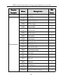
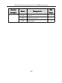
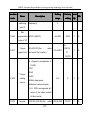
3.3 Control circuit terminals explain
4.
4.3
Terminal
Description
ON-OFF signal input, optical coupling with PW and COM.
S1~S7
Input voltage range: 9~30V
Input impedance: 3.3kΩ
High speed pulse or ON-OFF signal input, optical coupling with PW and
COM.
HDI
Pulse input frequency range: 0~50kHz
Input voltage range: 9~30V
PLC
P24
COM
AI1
Input impedance: 1.1kΩ
External power supply. +24V terminal is connected to PW terminal as
default setting. If the external power supply is needed, disconnect +24V
terminal with PLC terminal and connect PLC terminal with external power
supply.
Local power supply of +24V( current: 150mA)
The common terminal of +24V
Analog input; -10V~10V
Input impedance: 20kΩ
AI2
Analog input, 0~10V/ 0~20mA, switched by J16.
Input impedance: 10kΩ (voltage input) / 250Ω (current input)
+10V
+10V for the inverter.
29
JiaXing Jarol Scientific Instrument Co.,Ltd-JR6000 series products
GND
Common ground terminal of analog signal and +10V.
GND must be isolated from COM.
High speed pulse or open collector output terminal. The corresponding
HDO
common terminal is COM.
Output frequency range: 0~50 kHz
analog output terminals, of which AO1 can be selected to voltage output or
AO1、AO2
current output by J3; AO2 can be selected to voltage output or current
output by J4.
RA、RB、RC
TA、RB、TC
+ RS485 -
Output range:voltage(0~10V) /current (0~20mA)
R relay output,RA common,RB NC,RC NO.
Contact capacity:AC250V/3A,DC30V/1A
T relay output,TA common,TB NC,TC NO
Contact capacity:AC250V/3A,DC30V/1A
485 communication port. 485 differenticial signal, +,-. Please use twisted
pairs and shiled cables on the standard communication port.
30
JAROL Assumes the promotion of energy-saving technology as its own task!
3.4
Multi Functionsinput and output terminal connect
4.
4.3
.4Multi
Use the inside power +24V,External controller is the NPN type sinking current connect mode,as
this follow Figure:
Use the inside power +24V , External controller is the PNP type pull current connect mode,as
thisfollow Figure:
NOTES : pick off the short circuit slice between +24Vand PLC terminal , and connect the
31
JiaXing Jarol Scientific Instrument Co.,Ltd-JR6000 series products
shortcircuit between PLC and COM terminal.
Use the outside power External controller is the NPN type sinking current connect mode,as this
follow Figure:
NOTES:pick off the short circuit slice between +24Vand PLC terminal
Use the outsid power External controller is the PNP type pull current connect mode,as thisfollow Figure:
32
JAROL Assumes the promotion of energy-saving technology as its own task!
NOTES:pick off the short circuit slice between +24Vand PLC terminal
Use the inverter inside power +24Vand outside power’s multi functions output terminal connect mode:
NOTES : Use this connect mode ,if have HDO terminal bad ,please confirm the out connect Diode
polarity is right or wrong
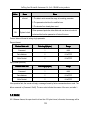
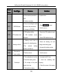
4.3.5 JUMPER ON CONTROL BOARD
Jumper
J4
J3
J2
Description
AO2 Voltage、Current(0~10V)/ (0~20mA) output change jumper,V and GND
short-circuit AO2 output voltage,I and GND short-circuit AO2 output current
AO1 Voltage、Current(0~10V)/ (0~20mA) output change jumper ,V and GND
short-circuit AO1 as output voltage , I and GND short-circuit AO1 as output
current.
AI2 Voltage(0~10V)/ (0~20mA)input change jumper,V and GND short-circuit
as input voltage,I and GND short-circuit as input current.
4.3.6 Control loop standard connection diagram
33
JiaXing Jarol Scientific Instrument Co.,Ltd-JR6000 series products
Figure 4-9 Control loop standard connection diagram
34
JAROL Assumes the promotion of energy-saving technology as its own task!
4.4 Installation Guidline to EMC Compliance
4.4.1 General knowledge of EMC
EMC is the abbreviation of electromagnetic compatibility, which means the device or system has the
ability to work normally in the electromagnetic environment and will not generate any electromagnetic
interference to other equipments. EMC includes two aspects: electromagnetic interference and
electromagnetic immunity.According to the transmission mode, Electromagnetic interference can be
divided into two categories: conducted interference and radiated interference.Conducted interference is
the interference transmitted by conductor. Therefore, any conductors (such as wire, transmission line,
inductor, capacitor and so on) are the transmission channels of the interference.Radiated interference is
the interference transmitted in electromagnetic wave, and the energy is inverse proportional to the square
of distance.Three necessary conditions or essentials of electromagnetic interference are: interference
source, transmission channel and sensitive receiver. Controlling these factors is right the point of settling
the EMC issue. For customers, the solution of EMC problem is mainly originated from transmission
channel because of transimitting source and receiver are not changable.
4.4.2 EMC features of inverter
Like other electric or electronic devices, inverter is not only an electromagnetic interference source but
also an electromagnetic receiver. The operating principle of inverter determines that it can generate
certain electromagnetic interference noise. At the same time inverter should be designed with certain
anti-jamming ability to ensure the smooth working in certain electromagnetic environment. Following is its
EMC features:
4.4.2.1 Input current is non-sine wave. The input current includes large amount of high-harmonic waves
that can cause electromagnetic interference, decrease the grid power factor and increase the line loss.
35
JiaXing Jarol Scientific Instrument Co.,Ltd-JR6000 series products
4.4.2.2 Output voltage is high frequency PMW wave, which can increase the temperature rise and
shorten the life of motor. And the leakage current will also increase, which can lead to the leakage
protection device malfunction and generate strong electromagnetic interference to influence the reliability
of other electric devices.
4.4.2.3 As an electromagnetic receiver, too strong external interference will cause malfunction and
damage. The inverter can not work normally.
4.4.2.4 In the system, EMS and EMI of inverter coexist. Decrease the EMI of inverter can increase
its EMS ability.
4.4.3 EMC Installation Guideline
In order to ensure all electric devices in the same system to work smoothly, this section, based on
EMC features of inverter, introduces EMC installation process in several aspects of application (noise
control, site wiring, grounding, leakage current and power supply filter). The good effective of EMC will
depend on the good effective of all of these five aspects.
4.4.3.1 Noise control
All the connections to the control terminals must use shielded wire. And the shield layer of the wire
must ground near the wire entrance of inverter. The ground mode is 360 degree annular connection
formed by cable clips. It is strictly prohibitive to connect the twisted shielding layer to the ground of
inverter, which greatly decreases or loses the shielding effect.
Connect inverter and motor with the shielded wire or the separated cable tray. One side of shield layer of
shielded wire or metal cover of separated cable tray should connect to ground, and the other side should
connect to the motor cover. Installing an EMC filter can reduce the electromagnetic noise greatly.
4.4.3.2 Site Wiring
36
JAROL Assumes the promotion of energy-saving technology as its own task!
Power supply wiring: the power should be separated supplied from electrical transformer. Normally it
is 5 core wires, three of which are fire wires, one of which is the neutral wire, and one of which is the
ground wire. It is strictly prohibitive to use the same line to be both the neutral wire and the ground wire
Device categorization: there are different electric devices contained in one control cabinet, such as
inverter, filter, PLC and instrument etc, which have different ability of emitting and withstanding
electromagnetic noise. Therefore, it needs to categorize these devices into strong noise device and noise
sensitive device. The same kinds of device should be placed in the same area, and the distance between
devices of different category should be more than 20cm.
Wire Arrangement inside the control cabinet: there are signal wire (light current) and power cable (strong
current) in one cabinet. For the inverter, the power cables are categorized into input cable and output
cable. Signal wires can be easily disturbed by power cables to make the equipment malfunction.
Therefore when wiring, signal cables and power cables should be arranged in different area. It is strictly
prohibitive to arrange them in parallel or interlacement at a close distance (less than 20cm) or tie them
together. If the signal wires have to cross the power cables, they should be arranged in 90 angles. Power
input and output cables should not either be arranged in interlacement or tied together, especially when
installed the EMC filter. Otherwise the distributed capacitances of its input and output power cable can be
coupling each other to make the EMC filter out of function.
ing
4.4.3.3 Ground
Grounding
Inverter must be ground safely when in operation. Grounding enjoys priority in all EMC methods
because it does not only ensure the safety of equipment and persons, but also is the simplest, most
effective and lowest cost solution for EMC problems.
Grounding has three categories: special pole grounding, common pole grounding and series-wound
grounding. Different control system should use special pole grounding, and different devices in the same
37
JiaXing Jarol Scientific Instrument Co.,Ltd-JR6000 series products
control system should use common pole grounding, and different devices connected by same power
cable should use series-wound grounding.
4.4.3.4 Leakage Current
Leakage current includes line-to-line leakage current and over-ground leakage current. Its value
depends on distributed capacitances and carrier frequency of inverter. The over-ground leakage current,
which is the current passing through the common ground wire, can not only flow into inverter system but
also other devices. It also can make leakage current circuit breaker, relay or other devices malfunction.
The value of line-to-line leakage current, which means the leakage current passing through distributed
capacitors of input output wire, depends on the carrier frequency of inverter, the length and section areas
of motor cables. The higher carrier frequency of inverter, the longer of the motor cable and/or the bigger
cable section area, the larger leakage current will occur.
Countermeasure
Countermeasure:
Decreasing the carrier frequency can effectively decrease the leakage current. In the case of motor
cable is relatively long (longer than 50m), it is necessary to install AC reactor or sinusoidal wave filter at
the output side, and when it is even longer, it is necessary to install one reactor at every certain distance.
4.4.3.5 EMC Filter
EMC filter has a great effect of electromagnetic decoupling, so it is preferred for customer to install it.
For inverter, noise filter has following categories:
�
Noise filter installed at the input side of inverter;
�
Install noise isolation for other equipment by means of isolation transformer or power filter.
4.4.4 The installation complies with following standards:
38
JAROL Assumes the promotion of energy-saving technology as its own task!
EN61000-6-4: Electromagnetic Interference Detection on the industrial condition.
EN61800-3: Comply with the electromagnetic radiation standard of EN61800-3 (The second
environment). Can comply with the electromagnetic radiation standard of EN61000-6-3(residence)
and standard of EN61000-6-4.
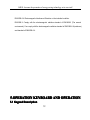
5.OPERATION KEYBOARD AND OPERATION
5.1 Keypad Description
39
JiaXing Jarol Scientific Instrument Co.,Ltd-JR6000 series products
5.1.1 Keypad schematic diagram
Figure 5-1
Operation Keyboard
5.1.2 Function key description
40
JAROL Assumes the promotion of energy-saving technology as its own task!
Key
Name
Program/Escape
Data enter Key
Function Description
Enter or escape from the first level menu,
Progressively enter menu and confirm parameters.
Digital modify key
Progressively increase data or function codes.
Digital modify key
Progressive decrease data or function codes.
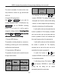
In parameter setting mode, press this button to select the bit
Shift Key
to be modified. In other modes, cyclically displays
parameters by right shift
Run Key
Start to run the inverter in keypad control mode.
In running status, restricted by F7.04, can be used to stop
Stop/Reset Key
the inverter. When fault alarm, can be used to reset the
inverter without any restriction.
41
JiaXing Jarol Scientific Instrument Co.,Ltd-JR6000 series products
Determined by Function Code F7.03:
0:
Display status switching
1:
Jog operation
2:
Switch between forward and reverse
3:
Clear the UP/DOWN settings.
4:
Quick debugging mode
Shortcut Key
+
Pressing the RUN and STOP/RST at the same time can
Combination Key
achieve inverter coast to stop.
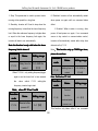
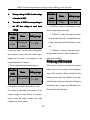
5.1.3 Indicator light description
1)Function Indicator Light Description
Unit indicator
Description
Extinguished: stop status
RUN/TUNE
Flickering: parameter autotuning status
Light on: operating status
Extinguished: forward operation
FWD/REV
Light on: reverse operation.
42
JAROL Assumes the promotion of energy-saving technology as its own task!
Unit indicator
Description
Extinguished: keypad control
LOC/REM
Flickering: terminal control
Light on: communication control
TRIP
Extinguished: normal operation status
Flickering: overload pre-warning status
2)Unit Indicator Light Description:
Unit indicator
Description
Hz
Frequency unit
A
Current unit
V
Voltage unit
RPM
Rotating speed unit
%
Percentage
3)Digital Display:
Have 5 digit LED , which can display all kinds of monitoring data and alarm codes such as reference
frequency, output frequency and so on.
。
43
JiaXing Jarol Scientific Instrument Co.,Ltd-JR6000 series products
�
5.2 Operation Process
This function code is not modifiable in
running status, but modifiable in stop status.
5.2.1 Parameter setting
5.2.2 Fault reset
Three levels of menu are:
If fault occurs to the inverter, it will inform the
�
Function code group (first-level);
related fault information. User can use STOP/RST
�
Function code (second-level);
or according terminals determined by F5 Group to
�
Function code value (third-level).
reset the fault. After fault reset, the inverter is in
Remarks:
Press
either
stand-by state. If user does not reset the inverter
the
PRG/ESC
or
the
when it is in fault state, the inverter will be in
DATA/ENT can return to the second- level
operation protection state, and can not run.
menu from the third- level menu. The
s
5.2.3Motor parameter
parameters
difference is: pressing DATA/ENT will save
autotuning
the set parameters into the control panel,
Input right nameplate parameter of the motor
and then return to the second- level menu
before the running of the inverter. JR6000 series
with shifting to the next function code
inverter matches the standard motor parameter
automatically; while pressing PRG/ESC
�
according to the nameplate. JR6000 series
will directly return to the second-class
inverter support parameter autotune to improve
menu without saving the parameters, and
the control perfprmance.
keep staying at the current function code.
The procedure of motor parameter autotuning is
This function code is not modifiable
as follows:
parameter, such as actual detected parameter,
Firstly, choose the keypad command channel as
operation records and so on;
the operation command channel (F0.01).
44
JAROL Assumes the promotion of energy-saving technology as its own task!
And then input following parameters according to
parameter autotune has been finished.
the actual motor parameters:
coupled from
Note: The motor should be dede-coupled
F2.01: motor rated power.
the load; otherwise, the motor parameters
F2.02: motor rated frequency;
obtained by autotuning may be incorrect.
5.2.4 Password setting
F2.03: motor rated speed;
F2.04: motor rated voltage;
JR6000 series inverter provides password
F2.05: motor rated current;
protection function to users. Set F7.00 to gain the
SetF0.16 to be 1, and for the detail process of
password and the password protection becomes
motor parameter autotuning, please refer to the
effective instantly after quitting form the function
description of Function Code F0.16. And then
code editing state. Press PRG/ESC again to the
press RUN on the keypad panel, the inverter will
function code editing state, "-----" will be displayed.
automatically calculate following parameter of the
Unless using the correct password, the operators
motor. See the instruction of F0.16 for the detailed
cannot enter it. Set F7.00 to 0 to cancel password
information.
protection function and the password cannot
F2.06: motor stator resistance;
protect the parameters in the quick menu.
5.2.5 Shortcut menu setting
F2.07: motor rotor resistance;
F2.08: motor stator and rotor inductance;
Shortcut menu, in which parameters in common
F2.09:motor
use can be programmed, provides a quick way to
stator
and
rotor
mutual
inductance;
view and modify function parameters. In the
F2.10: motor current without load;
shortcut menu, a parameter being displayed as
Then motor autotuning is finished.
“hF0.11” means the function parameter F0.11.
The keypad will display TUN-1 and TUN-2 during
Modifying parameters in the shortcut menu has
autotune. When the keypad displays -END-, the
the same effect as doing at normal programming
45
JiaXing Jarol Scientific Instrument Co.,Ltd-JR6000 series products
status.
Whether or not to display depends on setting the
5.3 Running State
corresponding binary bit of F7.08. Press the 》
/SHIFT to scroll through the parameters in right
5.3.1 Power-on initialization
order. Press DATA/ENT + QUICK/JOG to scroll
Firstly the system initializes during the inverter
through the parameters in left order.
power-on, and LED displays “JAROL”. After the
5.3.3 Operation
initialization is completed, the inverter is in
In running status, there are nineteen running
stand-by status
parameters which can be chosen to display or not.
5.3.2 Stand-by
multi-status
They are: running frequency, reference frequency,
parameters can be displayed. And these function
DC bus voltage, output voltage, output current,
can be choose to display through function code
rotating speed, line speed, output power, output
F7.06 and F7.07 (running parameters) and
torque, PID setting, PID feedback, ON-OFF input
F7.08(stop parameters) at the bineary bits. See
status, open collector output status, length value,
the description of F7.06, F7.07 andF7.08 for
count value, step number of PLC and multi-step
detailed definition.
speed, voltage of AI1, voltage of AI2, high speed
In stop status, there are ten stopping parameters
pulse input HDI frequency. Whether or not to
which can be chosen to display or not. They are:
display depends on setting the corresponding bit
reference frequency, DC bus voltage, ON-OFF
of F7.06, F7.07. Press the 》 /SHIFT to scroll
input status, open collector output status, PID
through the parameters in right order. Press
In
stop
or
running
status,
setting, PID feedback, analog input AI1 voltage,
DATA/ENT + QUICK/JOG to scroll through the
analog input AI2 voltage, HDI frequency, step
parameters in left order.
5.3.4 Fault
number of simple PLC and multi-step speed.
46
JAROL Assumes the promotion of energy-saving technology as its own task!
In fault status, inverter will display parameters of
STOP status besides parameters of fault status.
Press the
》 /SHIFT to scroll through the
parameters in right order . Press DATA/ENT +
QUICK/JOG to to scroll through the parameters in
left order.
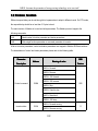
JR6000 series inverter offers a variety of fault
information. For details, see inverter faults and
their troubleshooting.
5.4 Shortcut Menu
Shortcut menu provides a quick way to view
and modify function parameters.
Seting the F7.03 to 4, the press QUICK/JOG, the
inverter will search the parameter which is
different from the factory seting, save these
parameters to be ready for checking. The buffer
length of shortcut menu is 32. So when the record
data beyonds to 32, can not display the overlength
part. Press
QUICK/JOGwill be the shortcut
debugging mode. If the UICK/JOG displays
“NULLF”, It means the parameters is the same
with the factory setting. If want to return to last
display, press QUICK/JOG.
47
JiaXing Jarol Scientific Instrument Co.,Ltd-JR6000 series products
accuracy, and quicker dynamic response, such as
machine
6.DETAILED
FUNCTION
DESCRIPTION
injection
molding
machine,
centrifugal machine and wire-drawing machine,
etc. One inverter only drives oine motor.
2. Torque control (sensorless vector control): It is
F0 Group Basic Function
suitable for the application with low accuracy
torque control, such as wired-drawing.
Function
Name
code
F0.00
tool,
Speed Control
Setting range
Note:
Set right nameplate parametes of the motor
0~2【0】
and
model
encoder
vector
This parameter is used to select the speed control
parameters
control
mode
when
and
selecting
complete
the
parameters autotune before running to get the
mode of the inverter.
right motor parameters. Only proper motor
0: V/F control: It is only suitable for motor
parameter can improve the high performance
commissioning cases where needs not high
of vector control.
accuracy or the cases where one inverter drives
Adjust
multiple motors.
F3
group
can
optimize
the
performance of vector control.
1: Sensorless vector control: It is only suitable for
motor commissioning cases or the cases where
Function
needs not high accuracy. This mode is applied in
code
Name
Setting range
Run
the universal high performance cases where the
F0.01
pulse encoder is not installed or the cases where
command
source
requires high torque at low speed, high speed
48
0~2【0】
JAROL Assumes the promotion of energy-saving technology as its own task!
UP/DOWN
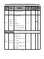
The control commands of inverter include: start,
setting
stop, forward run, reverse run, jog, and fault reset
and so on.
The frequency can be set by “∧”, “∨” and
0: Keypad (LED extinguished);
terminal UP/DOWN. This setting method have
Both RUN and STOP/RST key are used for
the highest and it cab be combined with setting
running command control. If Multifunction key
channel. It is used to adjust the output frequency
QUICK/JOG
during the comissioning of controlling system.
is set as FWD/REV switching
function (F7.03 is set to 2), it will be used to
0: valid, and the value can be saved when the
change the rotating orientation. In running status,
inverter is powered off. The frequency command
pressing RUN and STOP/RST in the same time
can be set and the value can be saved after the
will cause the inverter coast to stop.
inverter is powered off and it will combinate with
1: Terminal (LED flickering)
the current frequency when it is repowered on.
The operation, including forward run, reverse run,
1: valid, and the value can not be saved when
forward jog, reverse jog etc. can be controlled by
the inverter is powered off. The frequency
multifunctional input terminals.
command can be set but the value can not be
2: Communication (LED lights on)
saved after the inverter is powered off
The operation of inverter can be controlled by host
2: invalid, the function of “∧”, “∨” and
through communication.
terminal UP/DOWN is invalid, and the setting will
be cleared automatically.
Function
code
F0.02
3: valid during running. The function of “∧”,
Name
Setting range
“∨” and terminal UP/DOWN is valid during
Keypad and
running
0~3【0】
terminal
and
the
setting
will
be
automatically when the inverter stops.
49
cleared
JiaXing Jarol Scientific Instrument Co.,Ltd-JR6000 series products
When the factory setting is restored, the
Note
Note:When
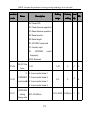
This is the lower limit of the output frequency of
value of keypad and UP/DOWN will be cleared.
the inverter.
Function
code
F0.03
This parameter can be selected by function code
Name
Setting range
F1.12. If the setting frequency is lower thanthe
Maximum 10.00~400.00 Hz
frequency
upper limit, the inverter will run, stop or hibernate
【50.00Hz】
at the lower limit frequency. The Max. Output
This parameter is used to set the Max. Output
frequency≥ Upper limit of the frequency≥Lower
frequency of the inverter. It is the basic of
limit of the frequency.
frequency setting and the speed of ACC/DEC.
Function
Please apy attention to it.
Function
code
Name
Keypad
Setting range
F0.06
Upper
F0.04
code
Name
F0.05~F0.03
setting
Setting
range
0.00~F0.03
【50.00Hz】
frequency
frequency limit 【50.00Hz】
When Frequency A command source is set to be
This is the upper limit of the output frequency and
Keypad, this parameter is the initial value of
it will be less than or equal to the Max. Output
inverter reference frequency.
frequency.
Function
code
Function
Name
Lower
F0.05
frequency
Setting
code
range
Name
Setting
range
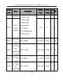
Frequency
0.00~F0.04
F0.07
【0.00Hz】
limit
A
command
source
50
0~7【0】
JAROL Assumes the promotion of energy-saving technology as its own task!
Select Frequency A command input channel and
Pulse specification: pulse voltage range 15~30V,
there are 8 main given frequency channels.
and pulse frequency range 0.0~50.0 kHz. 100% of
0: Keypad: Please refer to description of F0.06
the setting inpluse corresponds to maximal
Set the frequency by keypad through modifying
frequency, while -100% corresponds with minus
F0.06.
maximal frequency.
1: AI1
Note: pulse can only be input through
2: AI2
multi-function terminal HDI
HDI.. And set F5.00=0 to
Set the frequency through analog input terminals.
”.
select the function of HDI as “setting input
input”
JR6000 series inverters provide 2 ways analog
4. Simple PLC
input terminal in its standard configuration, of
The inverter will run at simple PLC when selecting
which AI1 is -10V~10V voltage input ; AI2 is
this frequency setting method. It is necessary to
0~10V/0(4) ~20mA input. The current/voltage can
set the parameter of FA group to determine the
be shifted by J2.
given frequency, running direction and each
Note: when AI2 selects 0~20mA input, 20mA
ACC/DEC time. Please refer to the instruction of
corresponds to 5V.
FA group carefully.
100.0% of analog input corresponds to the Max.
5. Multi-stage speed
Frequency
-100.0%
The inverter will run at multi-stage speed when
corresponds to the Max. Frequenxy in reverse
(function
code
F0.03),
selecting this frequeny setting method. The
(function code F0.03).
reference frequency is determined by F5 and FA
3: HDI
group. If F0.07 is not multi-stage speed setting,
The reference frequency is set by high speed
then the multi-stage setting has the priority which
pulse input. JR6000 series inverters provide 1 way
is lower than the priority of jogging. Only stage
HDI input in its standard configuration.
1~15 can be set when multi-stage setting has the
51
JiaXing Jarol Scientific Instrument Co.,Ltd-JR6000 series products
2:HDI
priority. So stage 1~15 can be set when F0.07 is
multi-stage speed setting.
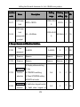
When B frequency command is the only frequency
6. PID control
reference channel, its application is the same with
The running mode is prodecure PID control
A frequency command. For details, please refer to
when selecting this parameter. It is e necessary to
F0.07.
set F9 group. The reference frequency is the
Function
result of PID adjustment. For details, please refer
code
Name
to description of F9 group
Setting range
Scale of
7. Remote Communication
F0.09
The frequency command is given by the upper
frequency
0~1【0】
B
monitor through communication given. Please
command
refer to MODBUS communication protocol in
0 : Maximum output frequency, 100% ofB
chapter 7. The reference frequency is set through
frequency setting
RS485. For details, please refer to Modbus
output frequency
protocol in Chapter7.
1 : A frequency command, 100% of B frequency
Function
code
Name
setting corresponds to the maximum output
Setting range
frequency. Select this setting if it needs to adjust
Frequency B
F0.08
corresponds to the maximum
command
on the base of A frequency command
0~2【0】
Note: If set AI2 to be 0~20mA input, the relative
source
voltage of 20mA is 5V. F0.09 is used when the
0:AI1
frequeny B is superimposed.
1:AI2
Function
52
Name
Setting range
JAROL Assumes the promotion of energy-saving technology as its own task!
model】
code
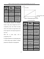
Frequency
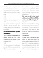
F0.10
Acceleration time is the time of accelerating from
0~3【0】
command
0Hz to maximum frequency (F0.03). Deceleration
selection Setting
time is the time of decelerating from maximum
0: Only frequency command source A is active.
frequency (F0.03) to 0Hz. Please refer to following
1: Only frequency command source B is active.
figure.
2: Both Frequency command source A and B are
active.
Reference frequency = reference frequency A +
reference frequency B.
3: Both Frequency command source A and B are
active.
Reference
Figure 6.1 Acceleration and deceleration time
frequency
=
Max
(reference
When the reference frequency is equal to the
frequency A, reference frequency B).
maximum frequency, the actual acceleration and
Note: Combination (0, 1 and 2) can be
deceleration time will be equal to actual setting.
switched by F5 group.
Function
code
Name
F0.12
maximum frequency, the actual acceleration and
Setting range
deceleration time will be less than actual setting.
Acceleration
F0.11
When the reference frequency is less than the
time 0
0.1~3600.0s
The actual acceleration (deceleration) time =
【Dependon
setting ACC/DEC time* reference frequency/
model】
Deceleration
0.1~3600.0s
time 0
【Dependon
maximum frequency.
1st group:
F0.11, F0.12
2nd group: F8.00, F8.01
53
JiaXing Jarol Scientific Instrument Co.,Ltd-JR6000 series products
3rd group:
F8.02, F8.03
4th group:
F8.04, F8.05.
Function
selected
by
combination
of
multifunctional
code
Name
Setting range
1.0~15.0kHz
ON-OFF input terminals
Function
Name
code
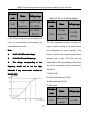
The acceleration and deceleration time can be
F0.14
Carrier
frequency
Setting range
【dependent on
the motor type】
Running
F0.13
direction
0~3【0】
selection
0: Runs at the default direction, the inverter runs in
the forward direction.
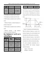
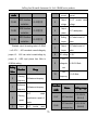
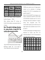
Figure 6.2 Effect of carrier frequency.
1: Runs at the oppositing direction, the inverter
The following table is the relationship between
runs in the reverse direction. This effect equals to
power rating and carrier frequency.
the shifting the rotation direction by adjusting
Highest
either two of the motor wires.
Carrier F
Carrier
Lowest Factory
Note: If the parameters are restored, the
F
running direction will be back to its original
Model
status.
Carrier
setting
kHz
kHz
kHz) (kHz
kHz)
( kHz ) F(kHz
kHz
(kHz
kHz)
2: Forbid to run in reverse direction: It can be used
0.4~11kW
15
1.0
8
15~55kW
8
1.0
4
in some special cases if the reverse running is
disabled.
54
JAROL Assumes the promotion of energy-saving technology as its own task!
75~630kW
6
1.0
AVR function is the output voltage automatic
2
adjustment function. When AVR is invalid, the
The advantage of high carrier frequency: ideal
output voltage will change with the intput voltage
current waveform, little current harmonic wave
(or DC bus voltage); when AVR is valid, the output
and motor noise.
voltage won’t change with the input voltage (or DC
The disadvantage of high carrier frequency:
bus voltage). The range of output voltage will keep
increasing the switch loss, increasing inverter
constant. If the site requirement is not met, AVR
temperature and the impact to the output capacity.
function can be cancled to shorten the DEC time.
The inverter needs to derate on high carrier
Function
frequency. At the same time, the leakage and
Name
code
electrical magnetic interference will increase.
Setting range
Motor
Applying low carrier frequency is contrary to the
F0.16
above, too low carrier frequency will cause
parameters
0~2【0】
autotuning
unstable running, torque decreasing and surge.
The manufacturer has set a reasonal carrier
0: No action: Forbidding autotuning.
frequency when the inverter is in factory. In
1: Rotation autotuning:
general, users do not need to change the
Input rigjht parameters of the motor nameplate
parameter.
(F2.01 - F2.05) and do not connect any load to
When the frequency used exceeds the default
the motor before performing autotuning and
carrier frequency, the inverter needs to derate
ensure the motor is in static and empty status.
20% for each additional 1k carrier frequency.
Otherwise the parameters detected by autotuning
Function
code
F0.15
Name
Setting range
AVR function
0~2【1】
will be incorrect.
Set the proper acceleration and deceleration time
(F0.11 and F0.12) according to the motor inertia
55
JiaXing Jarol Scientific Instrument Co.,Ltd-JR6000 series products
before performing autotuning. Otherwise it may
rotation autotuning except step c.
Function
cause over-current and over-voltage fault during
Name
code
autotuning.
Set F0.16 to be 1 then press the DATA/ENT,
Setting range
Restore
F0.17
LED will display “-TUN-” and flickers. During
0~2【0】
parameters
“-TUN-” is flickering, press the PRG/ESC to exit
0: No action
autotuning. Press RUN to start the autotung, and
1: Inverter restores all parameters to factory
the LED will display “TUN-0” and “TUN-1”
setting.
“RUN/TUNE” light will flicker. After a few minutes,
2: Inverter clear all fault records.
LED will display “-END-”. That means the
This function code will restore to 0 automatically
autotuning is finished and return to the stop status.
when complete the function operation.
When “-TUN-” flickers, pressing PRG/ESC can
F1 Group Start and Stop
Control
escape from the parameter autotune. During the
autotuning, press the STOP/RST will stop the
autotune.
Function
Note: Only keypad can control the autotuning.
code
F0.12 will restore to 0 automatically when the
F1.00
Name
Setting range
Start Mode
0~2【0】
autotuning is finished.
0: Start directly: Start the motor at the starting
2: Static autotuning:
frequency directly.
� If it is difficult to disconnect the load, static
1: DC braking and start: Inverter will output DC
autotuning is recommended.
current firstly and then start the motor at the
� The operation process is the same as
starting frequency. Please refer to description of
56
JAROL Assumes the promotion of energy-saving technology as its own task!
F1.03 and F1.04. It is suitable for the motor which
reference frequency is less than starting frequency,
have small inertia load and may reverse rotation
the inverter will be at stand-by status. The
when start.
indicator of RUN/TUNE lights on, inverter has no
2: Speed tracking and start: Inverter detects the
output. The starting frequency could be less than
rotation speed and direction of motor, then start
the lower frequency limits. The starting frequency
running to its reference frequency based on
takes no effect during FWD/REV switching
Function
current speed. This can realize smooth start of
rotating
motor
with
big
inertia
load
instantaneous power off.
F1.03
and above.
code
F1.01
0.0~150.0%
current
【0.0%】
before start
Name
DC Braking
Setting range
F1.04
Starting
0.00~10.00
frequency
【0.00Hz】
Hold time of
F1.02
Setting range
DC Braking
kW
Note: It only applies on the inverter of 11
11kW
Function
Name
code
when
starting
0.0~50.0s
time before
【0.0s】
start
During
the
DC
braking
before
F1.03,
the
increased current is the percentage to the rated
0.0~50.0s
current of the inverter.
【0.0s】
frequency
DC braking is invalid when F1.04 is set to be 0.
Set proper starting frequency can increase the
The bigger the DC braking current, the greater the
starting torque. The inverter runs from the starting
braking torques.
frequency and after the keeping time of the
Function
starting frequency, the inverter will accelerate to
code
the aimed frequency during the ACC time. If the
F1.05
57
Name
Setting range
Acceleration /
0~1【0】
JiaXing Jarol Scientific Instrument Co.,Ltd-JR6000 series products
Deceleration
frequency of
mode
DC braking
Waiting time
The frequency changing method during the
F1.08
running and starting of the inverter.
Output frequency will increase or decrease with
F1.09
fixed acceleration or deceleration time.
1: Reserved
code
F1.06
before DC
0.0~50.0s
【0.0s】
braking
0: Linear
Function
【0.00Hz】
F1.10
Name
Setting range
Stop mode
0~1【0】
DC braking
0.0~150.0%
current
【0.0%】
DC braking
0.0~50.0s
time
【0.0s】
Starting frequency of DC braking: Start the DC
braking when running frequency reaches starting
0: Deceleration to stop
frequency determined. Starting frequency of DC
When the stop command takes effect, the inverter
braking is 0 and the DC braking is invalid. The
decreases the output frequency and the defined
inverter will stop in the defined DEC time.
deceleration time till stop.
Waiting time before DC braking: Inverter blocks
1: Coast to stop
the output before starting the DC braking. After
When the stop command takes effect, the inverter
this waiting time, the DC braking will be started so
blocks the output immediately. The motor coasts
as to prevent over-current fault caused by DC
to stop by its mechanical inertia.
braking at high speed.
Function
code
F1.07
DC braking current: The value is the percentage of
Name
Setting range
Starting
0.00~F0.03
rated current of inverter. The bigger the DC
braking current is, the greater the braking torque
58
JAROL Assumes the promotion of energy-saving technology as its own task!
is.
DC braking time: The time used to perform DC
braking. If the time is 0, the DC braking will be
invalid.
Figure 6.4 FWD/REV dead time diagram.
Function
Figure 6.3 DC braking diagram.
Function
code
F1.11
Name
Setting range
Dead time of
0.0~3600.0s
FWD/REV
【0.0s】
code
Name
Setting range
Action when
running
frequency is
F1.12
0~2【0】
less than
Set the hold time at zero frequency in the
lower
transition between forward and reverse running.
frequency limit
It is shown as following figure:
This function code is used to define the running
state when the setting frequency is lower than the
lower frequency limit.
0: Running at the lower frequency limit: The
inverter runs at a frequency which is lower than
the lower frequency limit
59
JiaXing Jarol Scientific Instrument Co.,Ltd-JR6000 series products
1: Stop: This parameter is used to prevent motor
0: Disabled: Inverter will not automatically restart
running at low speed for a long time.
when power on again until run command takes
2: Stand-by: Inverter will Coast to stop when the
effect.
running frequency is less than the lower frequency
1: Enabled: When inverter is running, after
limit. When the reference frequency is higher than
power off and power on again, if run command
or equal to the lower frequency limit again, the
source is key control or communication control,
inverter will start to run automatically.
inverter will automatically restart after delay time
Note: the function is only valid when the lower
determined by F1.15
frequency limit is above 0.
This function only up 7.5KW type have,
Note:This
Function
code
please be cautious.
Name
Setting range
Delay time for
0.0~3600.0s
restart
【0】
F1.13
Function
code
Name
Setting range
Waiting time of
0.0~3600.0s
restart
【0.0s】
F1.15
When F1.12=2,only setting frequencybigger
Note: Valid when F1.14=1
again or as the lower limit ‘s time exceed
the
value
which
F1.13
Function
setting,the
code
frequency inverter begin start
when F1.12 as 2 valid
Note
Note:when
Function
code
Name
Name
Setting range
Terminal
function
Setting range
0~1【0】
F1.16
exmined when
Restart after
F1.14
power is on
0~1【0】
power off
This function only takes effect if run command
60
JAROL Assumes the promotion of energy-saving technology as its own task!
source is terminal control.
G/P unification, which means the power of the
If F1.15 is set to be 0, when power on, inverter will
motor used in G type is lower than the power of
not start even if FWD/REV terminal is active, until
the motor used in P type for one gear.
FWD/REV terminal disabled and enabled again.
The factory setting of the inverter is G model. If P
If F1.15 is set to be 1, when power on and
model is selected, it is necessary to set the
FWD/REV terminal is active, inverter will start
function code to 1 and reset the motor parameters
automatically.
of F2. For example, the factory setting of
Note:
JR6000-022G/030P-4 is 22kW G. If it is necessary
This function may cause the inverter restart
to change it to 30kW P, set F2.00 to 1 and reset
automatically, please use it with cautious.
the motor parameters of F2.
Function
Function
code
Name
code
Setting range
F2.01
Reversed
model】
F2 Group Motor Parameters
Motor rated
0.01Hz~F0.03
frequency
【50.00Hz】
F2.02
Name
Setting range
Inverter model
Motor rated
0~36000rpm
speed
【1460rpm】
F2.03
0~1【depend on
F2.00
【Depend on
power
F1.19
code
Setting range
0.4~3000.0kW
Motor rated
F1.17~
Function
Name
model】
F2.04
0: G model: Applicable to constant torque load.
Motor rated
voltage
1: P model: Applicalbe to constant power load.
F2.05
CHF100A series inverters apply the manner of
61
0~800V
【Depend on
model】
Motor rated
0.8~6000.0A
current
【Depend on
JiaXing Jarol Scientific Instrument Co.,Ltd-JR6000 series products
Function
Name
code
Setting range
F2.08
Motor leakage
0.1~6553.5mH
【Depend on
inductance
model】
model】
Note:
In
order
to
achieve
superior
F2.09
performance, please set these parameters
Motor mutual
The
inverter
F2.10
provides
parameters
【Depend on
inductance
according to motor nameplate, and then
perform autotuning.
0.1~6553.5mH
Current without
model】
0.1~6553.5A
【Depend on
load
model】
autotune.
Correct parameters autotune is from the right
After autotuning, the value of F2.06-F2.10 will be
setting of parameter of motor. The power rating of
automatically updated. These parameters are the
inverter should match the motor. If the bias is too
basic parameters for high performance V/F control
big, the control performances of inverter will be
which
deteriorated distinctly.
performance.
Reset
1
F2.0
2.01
can
initialize
code
F2.06
F2.07
direct
impact
to
the
control
Note: Do not change these parameters;
F2.06~F2.10
otherwise it may deteriorate the control
automatically.
Function
have
performance of inverter.
Name
Motor stator
resistance
Motor rotor
resistance
Setting range
F3 Group Vector Control
0.001~65.535Ω
Function
【Depend on
code
model】
Name
Setting range
ASR
0.001~65.535Ω
F3.00
【Depend on
proportional
gain Kp1
model】
62
0~100【20】
JAROL Assumes the promotion of energy-saving technology as its own task!
Function
code
F3.01
Name
Setting range
ASR integral
0.01~10.00s
time Ki1
【0.50s】
ASR switching
F3.02
lower
0.00~F3.05
【5.00Hz】
Figure 6-6
freqeuncy
ASR
F3.03
proportional
0~100
the proportion gain Kp is increased;
【15】
However, if Kp is too large, the system tends to
gain Kp2
F3.04
ASR integral
0.01~10.00s
time Ki2
【1.00s】
ASR switching
F3.05
lower
PI parameter diagram.
The system's dynamic response can be faster if
oscillate.
The system dynamic response can be faster if the
integral time Ki is decreased;
F3.02~F0.03
However, if Ki is too small, the system becomes
【10.00Hz】
overshoot and tends to oscillate.
freqeuncy
The adjustment procedure is as follow:
less than F3.02. F3.03 and F3.04 only take effect
� Increase the proportional gain (Kp) as far
when output frequency is greater than F3.05.
as possible without creating oscillation.
When output frequency is between F3.02 and
� Reduce the integral time (Ki) as far as
F3.05, Kp and KI are proportional to the bias
possible without creating oscillation.
between F3.02 and F3.05. For details, please
Function
refer to following figure.
code
F3.06
63
Name
Setting range
Slip
50%~200%
JiaXing Jarol Scientific Instrument Co.,Ltd-JR6000 series products
compensation
【100%】
1:AI1
rate of VC
2:AI2
The parameter is used to adjust the slip frequency
3: HDI
of vector control and improve the precision of
4:Multi-step speed
speed control. Properly adjust this parameter can
5:Communication
effectively restrain the static speed bias.
1~5: Torque control is valid, which defines the
Function
code
F3.07
torque setting source. When the torque setting is
Name
Torque upper
limit
Setting range
minus, the motor will reverse.
0.0~200.0%
Under speed control mode, output torque matches
【Depend on
load torque automatically, but limited byF3.07. If
model】
the load is above the set upper limit of the torque,
the output torque of the inverter will be limited, and
Note:
�
the rotation speed of the motor will change
100% setting corresponding to
rated current. G model : 150.0% ; P
automatically.
120.0%.
model
model:120.0%.
Under the torque control mode, the inverter will
�
output torque at the set command, but the output
Under torque control, F3.07 and
frequency is limited by the upper or lower limit.
F3.09 are all related with torque setting.
Function
code
F3.08
When the set torque is above the load torque, the
Name
Setting range
Torque setting
0~5
upper limit frequency; if the set torque is below the
source
【0】
load torque, the output frequency of the inverter
output frequency of the inverter will raise to the
will decrease to the lower limit frequency. If the
0: Keypad (F3.09)
64
JAROL Assumes the promotion of energy-saving technology as its own task!
output frequency of the inverter is limited, the
5:Communication
output torque will be different from the set torque.
Note:
Note:
maximum frequency.
�
Corresponds
to
F4 Group V/F Control
terminals.
Valid when F0.00=0.
Function
1~5: 100% corresponding to twice of
code
rated current of inverter.
�
100%
Speed control and torque control can
be switched by using multi-function input
�
1~4
When
inverter
decelerate
to
stop,
F4.00
Torque control model is switched to speed
code
F3.09
0~4【0】
0: Linear V/F curve. It is applicable for normal
constant torque load.
1: Multidots curve. It can be defined through
Name
Setting range
Keypad
-200.0~200.0%
2~4: Torque_stepdown curve. It is applicable for
torque setting
【50.0%】
variable torque load, such as blower, pump and so
setting (F4.03~F4.08).
Upper
F3.10
V/F curve
Setting range
selection
control mode automatically
Function
Name
frequency
on. Please refer to following figure.
0~5
【0】
setting source
Vb= Motor rated voltage Fb= Motor rated
Note
Note:Vb=
0: Keypad (F0.04)
frequency.
1:AI1
2:AI2
3:HDI
4:Multi-step speed
65
JiaXing Jarol Scientific Instrument Co.,Ltd-JR6000 series products
When the torque boost is set to 0.0%, the inverter
is in the automatic torque boost state.
Cut-off point of torque boost:the torque boost
is valid under this point, and the torque boost is
invalid when exceeding this set frequency.
Figure 6-7
Function
code
V/F Curve
Name
Setting range
0.0~10.0%
F4.01
F4.02
Torque boost
【0.0%】
Torque boost
0.0~50.0%
cut-off
【20.0%】
Figure 6-8
Function
Torque boost will take effect when output
code
Torque boost by hand
Name
Setting range
frequency is less than cut-off frequency of torque
boost (F4.02). Torque boost can improve the
F4.03
torque performance of V/F control at low speed.
V/F
0.00~F4.05
frequency1
【0.00Hz】
0.0~100.0%
The value of torque boost should be determined
F4.04
V/F voltage 1
【0.0%】
by the load. The heavier the load, the larger the
value is. If the boost is too large, the motor will run
F4.05
V/F
frequency 2
in exciting. The efficiency of the motor decreases
F4.03~F4.07
【0.00Hz】
0.0~100.0%
as the current of the inverter increases and the
F4.06
motor increase the heat-releasing.
66
V/F voltage 2
【0.0%】
JAROL Assumes the promotion of energy-saving technology as its own task!
Function
code
Name
Setting range
V/F
F4.05~F2.02
Function
frequency3
【0.00Hz】
code
Figure 6.9 V/F curve setting diagram.
F4.07
Name
0.0~100.0%
F4.08
V/F voltage3
V/F Slip
【0.0%】
F4.09
Setting range
0.0~200%
compensation
【0.0%】
limit
F4.03~F4.08 are used to set the user-defined V/F
curve. The value should be set according to the
The slip compensation function calculates the
load characteristic of motor.
torque of motor according to the output current
Note:
and compensates for output frequency. This
�
V1
V2
V3
rated voltage.
0<V1
V1<V2
V2<V3
V3<rated
�
f1
f2
f3
rated frequency.
0<f1
f1<f2
f2<f3
f3<rated
�
The
frequency
voltage
operating with a load. F4.09 sets the slip
low
compensation limit as a percentage of motor rated
set too high,
slip; the slip compensation limit is calculated as
corresponding
should not be
function is used to improve speed accuracy when
to
otherwise it may cause motor overheat or
the formula:
inverter fault.
F4.09=fb-n*p/60
Fb= Motor rated frequency (F2.02)
N= Motor rated speed (F2.03)
P= Motor poles
Function
code
Name
energy saving
F4.10
selection
67
Setting range
0~1【0】
JiaXing Jarol Scientific Instrument Co.,Ltd-JR6000 series products
F4.11~F4.12 are only valid in the V/F control
0:
Disabled
mode, When set F4.11 and F4.12 to be 0, the
1:
Enabled
restraining oscillation is invalid. While set the
While there is a light or empty load such as pumps
values to be 1~3 will have the effect of restraining
or fans, it will reduce the inverter output voltage
oscillation.When the running frequency is lower
and save energy through detecting the load
than F4.13, F4.11 is valid, when the running
current.
frequency higher than F4.13, F4.12 is valid.
F5 Group Input Terminals
This functions is good for fan and
Notes
Notes:This
pump application
Function
code
F4.11
There are 8 multi-function digital input terminals
and 2 analog input terminals in JR6000 series
Name
Setting range
inverters.
Low-frequenc
Function
y threshold of
code
0~10【2】
F5.00
restraining
oscillation
F4.12
Function
0~10【0】
code
oscillation
F4.13
restraining
HDI selection
0~1【0】
1: ON-OFF input
restraining
Boundary of
Setting range
0: High speed pulse input
High-frequenc
y threshold of
Name
Name
S1 terminal
F5.01
Setting range
0~39【1】
function
0.00Hz~F0.03
S2 terminal
【30.00Hz】
F5.02
oscillation
function
68
0~39【4】
JAROL Assumes the promotion of energy-saving technology as its own task!
Function
code
Name
S3 terminal
F5.03
Setting range
F5.04
Jog forward
5
Jog reverse
0~39【7】
function
S4 terminal
4
6
0~39【0】
function
7
Function
code
Name
Setting range
S5 terminal
0~39【0】
F5.05
function
8
S6 terminal
0~39【0】
F5.06
function
S7 terminal
0~39【0】
F5.07
function
9
HDI terminal
0~39【0】
F5.08
function
0
1
Invalid
Forward
2
Reverse
3
3-wire control
Please set unused
terminals to be
invalid to avoid
malfunction
Please refer to
description of
F5.10.
Please refer to
description of
F8.06~F8.08.
The inverter blocks
the output
immediately. The
Coast to stop
motor coasts to
stop by its
mechanical inertia.
Resets faults that
have occurred. It
Reset fault
has the same
function as
STOP/RST.
When this terminal
takes effect,
inverter
decelerates to stop
and save current
status, such as
Pause running
PLC, traverse
frequency and
PID. When this
terminal takes no
effect, inverter
restores the status
Stop the inverter
and output an
External
fault
alarm when a fault
input
occurs in a
peripheral device.
10:Up command(UP)
11:DOWN command(DOWN)
12:Clear UP/DOWN
The reference frequency of inverter can be
adjusted by UP command and DOWN command.
Please refer to
description of
F5.10.
These three functions are used to modify the
69
JiaXing Jarol Scientific Instrument Co.,Ltd-JR6000 series products
combination of these two terminals:
reference frequency through external terminals.
UP is the increasing command, DOWN is the
Terminal Terminal ACC
ACC//DEC
decreasing command, and the Clear UP/DOWN is
used to restore to the reference frequency given
2
1
OFF
OFF
by the frequenxy command channel.
13:Switch between A and B
14:A setting and
Switch between A and B
OFF
15:B setting and Switch between A and B
ON
16、17、18、19:Multi step speed1~4
16 steps speed control can be realized by the
ON
OFF
ON
ON
combination of these four terminals. For details,
please refer to: Multi-step speed reference
terminal status and according step value table
time select
parameter
ACC
ACC//DEC
F0.11
time 0
F0.12
ACC
ACC//DEC
F8.00
time 1
F8.01
ACC
ACC//DEC
F8.02
time 2
F8.03
ACC
ACC//DEC
F8.04
time 3
F8.05
23:Reset simple PLC when stop
Multi speed terminal 1 is low
Notes
Notes:Multi
When simple PLC stops, the status of PLC
4 is high position.
position
position,4
such as running step, running time and running
Multi 4
Multi3
Multi 2
Multi1
BIT3
BIT2
BIT1
BIT0
frequency will be cleared when this terminal is
enabled.
20:Multi speed stop
24:Pause simple PLC
Keep current step unchanged no matter what
Inverter runs at zero frequency and PLC
the input
pauses the timing when this terminal is enabled. If
21、22:ACC/DEC time select terminal 1、2
this terminal is disabled, inverter will start and
groups of ACC/DEC time can be selected by the
continue the PLC operation from the status before
70
JAROL Assumes the promotion of energy-saving technology as its own task!
pause.
UP/DOWN setting is invalid but will not be
25:Pause PID
cleared.
PID adjustment will be paused and inverter
UP/DOWN value before will be valid again.
When
this
terminal
is
disabled,
33~39:Reserved
keeps output frequency unchanged.
26:Pause traverse operation
Function
Name
code
Inverter keeps output frequency unchanged.
If this terminal is disabled, inverter will continue
F5.09
traverse operation with current frequency.
ON-OFF filter
Setting range
0~10【5】
times
27:Reset traverse operation
This parameter is used to set filter strength of
Reference frequency of inverter will be forced
terminals (S1~S7, HDI). When interference is
as center frequency of traverse operation.
heavy, user should increase this value to prevent
28:Reset counter
malfunction.
Clear the value of counter.
Function
29:Forbid torque control mode
Name
code
Torque control is forbided and switch inverter
Terminal
F5.10
to run in speed control mode.
Setting range
0~3【0】
control mode
30:Forbid the function of ACC/DEC
This parameter defines four different control
ACC/DEC is invalid and maintains output
modes that control the inverter operation through
frequency if it is enabled.
external terminals.
31:Counter input
0: 2-wire control mode 1: Integrate REV/FWD
The pulse input terminal of internal counter.
command with run direction.
Maximum pulse frequency: 200Hz.
K1
K2
Run command
OFF
OFF
Stop
32:UP/DOWN invalid temporarily
71
JiaXing Jarol Scientific Instrument Co.,Ltd-JR6000 series products
ON
OFF
SB2:Stop button
FWD
OFF
ON
REV
ON
ON
Maintenance
Sin set for 3 NO. function3-wires running
contry multi-functions input terminal .
3:3-wire control mode 2
Figure 6.9 2-wire control mode 1.
1 : 2-wire control mode 2: START/STOP
SB1: Forward run button
command is determined by FWD terminal. Run
SB2: Stop button (NC)
direction is determined by REV terminal.
SB3: Reverse run button
K1
K2
Run command
OFF
OFF
Stop
ON
OFF
FWD
OFF
ON
Stop
ON
ON
REV
Figure 6.102-wire control mode 2.
2 : 1: Terminal SIn is the multifunctional input
Figure 6-12
3-wire control mode 2.
SB1:FWD/REV key
terminal,run command by FWD,direction control
SB2:Stop button
by REV.Sin always close input .
SB3:REV Running button
K
Run command
OFF
FWD
Note: When 2-wire control mode is active, the
ON
REV
inverter will not run in following situation even
if FWD/REV terminal is enabled:
Figure 6.121 3-wire control mode 1.
�
K:FWD/REV key
Coast
to
stop
(press
RUN
STOP/RST at the same time).
SB1:Run button
72
and
JAROL Assumes the promotion of energy-saving technology as its own task!
�
Stop
command
from
serial
use
function
Some
communication.
communication.S
see F7.04
These
parameters
relationship
determine
between
analog
the
input
voltage and the corresponding setting
value. When the analog input voltage
Figure 6-13
exceeds the range between lower limit
Relationship between AI and
corresponding setting.
and upper limit, it will be regarded as the
AI1 filter time constant is effective when there
upper limit or lower limit.
are sudden changes or noise in the analog input
The analog input AI1 can only provide
signal. Responsiveness decreases as the setting
voltage
increases.
input,
and
the
range
is
-10V~10V.
For
different
Function
applications,
the
code
Name
corresponding value of 100.0% analog
Setting range
0.00~10.00V
setting is different. For details, please
F5.17
AI2 lower limit
F5.18
corresponding
refer to description of each application.
【0.00V】
AI2 lower limit
-100.0~100.0%
Note: AI1 lower limit must be less or
equal to AI1 upper limit.
【0.0%】
setting
0.00~10.00V
F5.19
AI2 upper limit
-100.0~100.0%
corresponding
【100.0%】
F5.20
73
【10.00V】
AI2 upper limit
JiaXing Jarol Scientific Instrument Co.,Ltd-JR6000 series products
Function
Name
code
Function
Setting range
code
setting
F5.26
AI2 filter time
0.00~10.00s
constant
【0.10s】
F5.21
Setting range
HDI lower
0.00~50.00kHz
limit
【0.00kHz】
terminal in JR6000
Function
code
limit
-100.0~100.0%
corresponding
【0.0%】
F6.00
series inverters.
Name
HDO
Setting range
0~1【0】
select
0: High-speed pulse output: The maximum pulse
HDI upper
0.00~50.00kHz
frequency is 50.0 kHz. Please refer to description
limit
【50.00kHz】
of F6.06.
1: ON-OFF output: Please refer to description of
HDI upper
F5.25
【0.10s】
terminal and 1 multi-function analog output
Name
setting
F5.24
constant
2 multi-function relay output terminals, 1 HDO
HDI lower
F5.23
0.00~10.00s
There are 1 multi-function digital output terminal,
voltage is 5V
5V。
F5.22
HDI filter time
F6 Group Output Terminals
when AI2 select 0~20mA input 20mA as the
code
Setting range
The description of F5.22~F5.26 is similar to AI1.
Analog value AI2 can set 0~10V/0~20mA input
Function
Name
limit
-100.0~100.0%
corresponding
【100.0%】
F6.01.
Function
code
setting
74
Name
Setting range
JAROL Assumes the promotion of energy-saving technology as its own task!
8 : Preset count value reached , Please refer to
HDO ON-OFF
F6.01
output
0~20【1】
description of F8.18.
9:Specified count value reached,Please refer to
selection
Relay 1 output
F6.02
description of F8.19.
0~20【4】
10:overload pre-warming of inverter,Please refer
selection
to description of Fb.04~Fb.06
Relay 2 output
F6.03
selection
11:Simple PLC step completed
0~20【0】
, After simple PLC completes one step, inverter
(4.0kW and
will output ON signal for 500ms.
above)
12 : PLC cycle completed , fter simple PLC
OC/Relay output functions are indicated in
completes one cycle, inverter will output ON signal
the following table:
for 500ms.
0:No output.
1:Running,ON: Run command is ON or voltage
13:Running time reached,ON: The accumulated
is being output.
running time of inverter reaches the value of
2:Run forward,ON: During forward run.
F8.20.
14 : Upper frequency limit reached , ON:
3:Run reverse,ON: During reverse run.
Running frequency reaches the value of F0.04.
4:Fault output,ON: Inverter is in fault status.
15 : Lower frequency limit reached , ON:
5 : FDT reached , Please refer to description of
Running frequency reaches the value of F0.05.
F8.21, F8.22.
16: Ready, ON: Inverter is ready (no fault,
6:Frequency reached,Please refer to description
power is ON).
of F8.23.
17~20:Reserved
7:Zero speed running,ON: The running frequency
Function
of inverter and setting frequency are zero.
75
Name
Setting range
JiaXing Jarol Scientific Instrument Co.,Ltd-JR6000 series products
code
AO1 function
F6.04
F6.05
AO2 function
Output
0~1.5* inverter rated
voltage
voltage
Output
0~10【0】
5
selection
0~2* rated power
power
0~10【0】
Setting
0~2*rated current of
torque
motor
Output
0~2*rated current of
torque
motor
6
selection
Standard output the analog value is 0~20mA
7
(or 0~10V),AO1 can select current/voltage by
jumper J3 , AO2 can select current/voltage by
8
AI1 voltage 0~10V
jumper J4 。 HDO input plause from 0kHz to
AI2
50.00kHz setting.
9
voltage/cur
Setting
Function
current
4
selection
HDO function
F6.06
0~10【0】
current
0~10V/0~20mA
rent
Range
Value
HDI
10
Running
0
0.1~50.0kHz
frequency
0~Maximum frequency
frequency
Reference
1
Function
0~Maximum frequency
frequency
code
0~2*
rated
Setting range
0.0~100.0%
Running
2
Name
F6.07
synchronous speed of
AO1 lower limit
【0.0%】
speed
motor
3
Output
0~2*
inverter
AO1 lower limit
0.00~10.00V
corresponding
【0.00V】
F6.08
rated
76
JAROL Assumes the promotion of energy-saving technology as its own task!
Function
Name
code
Setting range
output
0.0~100.0%
F6.09
AO1 upper limit
【100.0%】
AO1 upper limit
0.00~10.00V
F6.10
corresponding
Figure 6.14 Relationship between AO and
【10.00V】
corresponding setting.
output
These parameters determine the relationship
Function
between analog output voltage/current and the
code
corresponding output value. When the analog
F6.11
Name
0.0~100.0%
AO2 lower limit
output value exceeds the range between lower
F6.12
lower limit.
AO1
is
current
output,
1mA
【0.0%】
AO2 lower limit
limit and upper limit, it will output the upper limit or
When
Setting range
0~10.00V
corresponding
【0.00V】
output
is
corresponding to 0.5V.
F6.13
0.0~100.0%
AO2 upper limit
For different applications, the corresponding value
【100.0%】
AO2 upper limit
of 100.0% analog output is different. For details,
F6.14
please refer to description of each application.
0.00~10.00V
corresponding
【10.00V】
output
77
0.0~100.0%
F6.15
HDO lower limit
F6.16
HDO lower limit 0.00~50.00kHz
【0.0%】
JiaXing Jarol Scientific Instrument Co.,Ltd-JR6000 series products
Function
code
F7.00 is set to be 00000, user’s password set
Name
Setting range
before will be cleared and the password protection
corresponding
【0.00kHz】
function will be disabled.
After the password has been set and becomes
output
F6.17
HDO upper limit
0.0~100.0%
valid, the user can not access menu if the user’s
【100.0%】
password is not correct. Only when a correct
HDO upper limit
F6.18
user’s password is input, the user can see and
0.00~50.00kHz
corresponding
modify the parameters. Please keep user’s
【50.00kHz】
output
password in mind.
The password protection becomes valid in 1
minute after quitting form the function code editing
state. Press PRG/ESC again to the function code
editing state, “0.0.0.0.0”will be displayed. Unless
using the correct password, the operators cannot
Figure 6.15 Relationship between HDO and
enter it.
corresponding setting.
F7 Group Display Interface
Function
code
F7.00
Name
User
Function
Name
Setting range
F7.01
Reserved
0~1【0】
F7.02
Reserved
0~2【0】
code
Setting range
0~65535【0】
password
F7.03
The password protection function will be valid
when F7.00 is set to be any nonzero data. When
78
QUICK/JOG
function
0~4【0】
JAROL Assumes the promotion of energy-saving technology as its own task!
selection
�
The RESET function of STOP/RST is
QUICK/JOG is a multifunctional key, whose
always valid.
Function
function can be defined by the value
Name
code
0. Display status switching
1: Jog: Press QUICK/JOG, the inverter will jog.
Setting range
Keypad
2: FWD/REV switching: Press QUICK/JOG , the
display
F7.05
0~3【0】
selection
running direction of inverter will reverse. It is only
valid if F0.03 is set to be 0.
0: When external keypad exists, local keypad will
3: Clear UP/DOWN setting: Press QUICK/JOG,
be invalid.
the UP/DOWN setting will be cleared.
1: Local and external keypad display
4. Quick debugging mode
simultaneously, only the key of external keypad is
Function
code
Name
valid.
Setting range
2: Local and external keypad display
STOP/RST
F7.04
function
simultaneously, only the key of local keypad is
0~3【0】
valid.
selection
3: Local and external keypad display
0: Valid when keypad control 1: Valid when
simultaneously, both keys of local and external
keypad or terminal control
keypad are valid.
2: Valid when keypad or communication control
Note: This function should be used cautiously,
3: Always valid
otherwise it may cause malfunction.
Note:
�
Function
The value of F7.04 only determines the
code
STOP function of STOP/RST
STOP/RST..
F7.06
79
Name
Setting range
Running
0~0xFFFF
JiaXing Jarol Scientific Instrument Co.,Ltd-JR6000 series products
status display 【0x07FF】
selection 1
voltage voltage
When the JR6000 series frequency inverter
example inputposition display 3,means S1 ,S2
parameters in right order . Press DATA/ENT +
always close,other terminal break,the detailed
QUICK/JOG to scroll through these parameters in
information please check F7.23 and F7.24
left order.
Function
The display content corresponding to each bit of
Name
code
F7.06 is described in the following table:
BIT11
y
the system,S1(HDO) as lowest position For
Press 》/SHIFT to scroll through these
BIT12
freque
Input /output terminal condition display by into
code ,If Bit is 1, the parameter will be displayed.
BIT14 BIT13
frequenc
ncy
running,parameter display effect by function
BIT15
nce
Setting range
Running
BIT10
F7.07
status display
Step No.
0~0xFFFF
【0x0000】
selection 2
of PLC
Torque Output
Input
PID
Count
or
setting terminal terminal feedba
The display content corresponding to each bit of
value
multi-ste
value
status
status
ck
BIT7
BIT6
BIT5
BIT4
F7.8 is described in the following table:
p
BIT9
BIT15 BIT14 BIT13 BIT12 BIT11 BIT10
BIT8
PID
Output Output
Line
Rotation Output
preset
torque power
speed
speed current
BIT3
BIT2
BIT1
Reserve Reserv Reserv Reserv Reserv
Reserved
d
BIT9
BIT0
ed
ed
ed
ed
BIT8 BIT7 BIT6 BIT5
BIT4
Reserve Reserv Reserv Reserv Reserv Inverter
Output DC bus Refere Running
d
80
ed
ed
ed
ed
overload
JAROL Assumes the promotion of energy-saving technology as its own task!
%
BIT3
d
d
d
d
d
BIT9
BIT8
BIT7
BIT6
BIT5
PLC
HDI
BIT2 BIT1 BIT0
value
Motor
overload HDI
AI2
e set
AI1
BIT4
PID
PID
%
Function
Name
code
feedbac
AI2
AI1
BIT1
BIT0
preset
k
Setting range
Stop status
0~0xFFFF
display selection
【0x07FF】
F7.08
BIT3
BIT2
output
Input
Set
DC BUS frequen
terminal terminal
7.08 determines the display parameters in stop
cy
status. The setting method is similar with F.7.06
Function
code
F7.09
Name
Setting range
Coefficient of
0.1~999.9%
rotation speed
【100.0%】
This parameter is used to calibrate the bias
between actual mechanical speed and rotation
speed. The formula is as below:
Actual mechanical speed = 120 * output frequency
Stop status display as follow:
BIT15
BIT14
BIT13
BIT12
F7.09 / Number of poles of motor.
BIT1
Function
0
code
BIT11
Reserve Reserve Reserve Reserve Reserve Torqu
F7.10
81
Name
Setting range
Coefficient of
0.1~999.9%
JiaXing Jarol Scientific Instrument Co.,Ltd-JR6000 series products
【1.0%】
line speed
protection point of different model may be
This parameter is used to calculate the line speed
different.
based on actual mechanical speed. The formula is
IGBT
as below:
temperature of IGBT module. Overheat protection
module
temperature:
Indicates
the
Line speed = actual mechanical speed *F7.10
point of different model may be different.
Function
Software version: Indicates current software
Name
code
Setting range
version
Rectify module
0~100.0℃
F7.11
temperature
Function
IGBT module
code
0~100.0℃
F7.12
F7.17
temperature
F7.13
Software version
F7.18
0~3000kW
Inverter rated
F7.19
【Depend on
F7.14
power
current
Function
Accumulated
F7.16
0~65535h
code
running time
temperature:
rectify
Indicates
module.
Name
Third latest
fault type
Second latest
fault type
Latest fault
type
Setting range
0~25
0~25
0~25
analysis.
model】
of
time:
are 25 faults. For details, please refer to fault
【Depend on
F7.15
temperature
running
0 means there is no fault and 0~25 means there
0.0~6000A
Inverter rated
module
DSP.Accumulated
These parameters record three recent fault types.
model】
Rectify
of
Displays accumulated running time of inverter.
the
F7.20
Name
Output
frequency at
Overheat
82
Setting range
JAROL Assumes the promotion of energy-saving technology as its own task!
current fault
F7.21
F7.22
F7.23
terminal status at current fault.
Output current
This value is displayed as decimal. The meaning
at current fault
of each bit is as below::
DC bus
BIT3
BIT2
BIT1
BIT0
voltage at
Reserved
RO2
RO1
HDO
current fault
1 indicates corresponding output terminal is ON,
Input terminal
while 0 indicates OFF. Notice: This value is
status at
displayed as decimal.
d Function
F8Group Enhance
Enhanced
current fault
F7.24
Output
Function
terminal status
code
Name
at current fault
0.1~3600.0s
F8.00
1 indicates corresponding input terminal is ON,
Acceleration
time 1
while 0 indicates OFF. This value records output
terminal status at current fault.
Setting range
This value is
F8.01
displayed as decimal. The meaning of each bit is
Deceleration
time 1
as below:
BIT7
BIT6
BIT5
BIT4
HDI
S7
S6
S5
BIT3
BIT2
BIT1
BIT0
S4
S3
S2
S1
F8.02
Acceleration
time 2
Deceleration
F8.03
1 indicates corresponding input terminal is ON,
while 0 indicates OFF. This value records output
83
time 2
【Depend on
model】
0.1~3600.0s
【Depend on
model】
0.1~3600.0s
【Depend on
model】
0.1~3600.0s
【Depend on
model】
JiaXing Jarol Scientific Instrument Co.,Ltd-JR6000 series products
0.1~3600.0s
F8.04
F8.05
Acceleration
time 3
Deceleration
model】
Function
0.1~3600.0s
code
【Depend on
time 3
and the
above
model】
Name
Setting range
Skip
0.00~F0.03
Frequency 1
【0.00Hz】
F8.09
model】
ACC/DEC time can be seleted among F0.11,
F0.12
time
【Depend on
three
Skip
0.00~F0.03
Frequency 2
【0.00Hz】
F8.10
groups. Their
meanings are the same. Please refer to the
Skip
relative instructions of F0.11 and F0.12.
F8.11
Select the ACC/DEC time 0~3 through the
frequency
0.00~F0.03
【0.00Hz】
bandwidth
different combination of the multi-function digital
By means of setting skip frequency, the inverter
terminals when the inverter runs.
can keep away from the mechanical resonance
Function
code
F8.06
F8.07
F8.08
Name
with the load. F8.09 and F8.10 are centre value of
Setting range
frequency to be skipped.
Jog reference
0.00~F0.03
Notice:
【5.00Hz】
Jog
0.1~3600.0s
acceletation
【Depend on
time
model】
Jog
0.1~3600.0s
deceleration
【Depend on
�
.11 is 0, the skip function is invalid.
If F8
F8.11
�
.09 and F8.10 are 0, the skip
If both F8
F8.09
.11
function is invalid no matter what F8
F8.11
is.
�
Operation is prohibited within the skip
frequency
84
bandwidth,
but
changes
JAROL Assumes the promotion of energy-saving technology as its own task!
during acceleration and deceleration
frequency as its center. The route of the running
are smooth without skip.
frequency is illustrated as below, of which the
traverse is set by F08.12 and when F08.12 is set
as 0, the traverse is 0 with no function.
Figure6-16
Function
code
Skip frequency diagram.
Name
Figure 6.17 Traverse operation diagram.
Setting range
Traverse range:The traverse running is limited by
F8.12
Traverse
amplitude
0.0~100.0%
F8.13
Jitter
frequency
0.0~50.0%
F8.14
Rise time of
traverse
0.1~3600.0s
F8.15
Fall time of
traverse
0.1~3600.0s
upper and low frequency.
【0.0%】
The
traverse
range
frequency:traverse
relative
range
to
AW
the
center
=
center
【0.0%】
frequency×traverse range F08.12.
Sudden jumping frequency = traverse range
【5.0s】
AW×sudden jumping frequency range F08.13.
When run at the traverse frequency, the value
【5.0s】
which is relative to the sudden jumping frequency.
Traverse function applies to the industries where
The raising time of the traverse frequency : The
need the traverse and convolution function such
time from the lowest point to the highest one.
as textile and chemical fiber industries.
The declining time of the traverse frequency :The
The traverse function means that the output
time from the highest point to the lowest one.
frequency of the inverter is fluctuated with the set
85
JiaXing Jarol Scientific Instrument Co.,Ltd-JR6000 series products
Function
code
F8.16
F8.17
count value (F8.18), it will output an ON-OFF
Name
Setting range
signal. Inverter will clear the counter and restart
counting.
Auto reset
0~3【0】
If function of output terminal is set as specified
times
Reset interval
0.1~100.0s
count reached, when the count value reaches
【1.0s】
specified count value (F8.19), it will output an
The times of the fault reset: the inverter set the
ON-OFF signal until the count value reaches
fault reset times by selecting this function. If the
preset count value (F8.18). Inverter will clear the
reset times exceed s this set value, the inverter
counter and restart counting.
will stop for the fault and wait to be repaired.
Note:
The interval time of the fault reset:The interval
�
not be greater than preset count value
between the time when the fault occurs and the
(F8.18).
time when the reset action occurs
Function
code
�
Name
F8.18
Preset count
value
F8.19
Specified
count value
Specified count value (F8.19) should
Setting range
Output terminal can be RO1, RO2 or
HDO.
This function is shown as following figure.
F8.19~65535
【0】
0~F8.18【0】
The count pulse input channel can be S1~S4
(≤200Hz) and HDI.
Figure 6.18 Timing chart for preset and specified
If function of output terminal is set as preset count
count reached.
reached, when the count value reaches preset
86
JAROL Assumes the promotion of energy-saving technology as its own task!
Function
code
F8.20
Name
Setting range
Preset running
0~65535h
time
【65535h】
Pre-set running time of the inverter.
When the accumulative running time achieves the
set time, the multi-function digital output terminals
will output the signal of “running time arrival”.
Function
code
Name
Figure 6-19 FDT level and lag diagram.
Setting range
Function
F8.21
FDT level
F8.22
FDT lag
0.00~F0.03
Name
code
【50.00Hz】
Setting range
Frequency
0.0~100.0
F8.23
【5.0%】
When the output frequency reaches a certain
arrive
0.0~100.0%
detecting
【0.0%】
range
preset frequency (FDT level), output terminal will
When output frequency is within the detecting
output an ON-OFF signal until output frequency
range of reference frequency, an ON-OFF signal
drops below a certain frequency of FDT level
will be output. The function can adjust the
(FDT level - FDT lag), as shown in following
detecting range.
figure.
87
JiaXing Jarol Scientific Instrument Co.,Ltd-JR6000 series products
between load and output frequency is in the
following figure.
Figure 6.20 Frequency arriving detection
diagram.
Function
code
F8.24
Name
Droop control
Setting range
0.00~10.00Hz
Figure 6.21 Droop control diagram.
【0.00Hz】
Function
When several motors drive the same load, each
code
motor's load is different because of the difference
of motor's rated speed. The load of different
F8.25
motors can be balanced through droop control
function which makes the speed droop along with
Name
Setting range
Brake
115.0~140.0%
threshold
【Depand on
voltage
Model】
When the DC bus voltage is greater than the value
load increase. When the motor outputs rated
of F8.25, the inverter will start dynamic braking.
torque, actual frequency drop is equal to F8.24.
Notice:
User can adjust this parameter from small to big
�
gradually during commissioning. The relation
Factory setting is 120% if rated voltage
of inverter is 220V.
88
JAROL Assumes the promotion of energy-saving technology as its own task!
�
�
Function
Factory setting is 130% if rated voltage
of inverter is 380V.
code
5 is corresponding to
The value of F8.2
8.25
F8.28
the DC bus voltage at rated input
code
PWM
0~2【0】
Noise in higher frequency is high
Name
1:PWM as 2,noise is so lower when motor
Setting range
working under this mode,but temperature rise
Cooling fan
F8.26
Setting range
0:PWM as 1,Noise in lower frequency is low,
voltage.
Function
Name
is high,select the small KW frequency inverter
0~1【0】
control
use
2:PWM as 3,noise is so high when motor
0: Auto stop mode: The fan keeps working when
the inverter is running. When the inverter stops,
working under this mode,Be more effective to
whether the fan works or not depends on the
restrain the oscillation
module temperature of inverter.
F9 Group PID Control
1: The fan keeps working when powering on.
PID control is a common used method in process
Function
code
F8.27
control, such as flow, pressure and temperature
Name
Setting range
control. The principle is firstly to detect the bias
Overmodulatio
between preset value and feedback value, then
0~1【0】
calculate output frequency of inverter according to
n
0: the function is invalid 1: the function is valid
proportional gain, integral and differential time.
The function is applicable in the instance of low
Please refer to following figure.
network voltage or heavy load for a long time,
inveter raises the output voltage with rising
utilization rate of bus voltage.
89
JiaXing Jarol Scientific Instrument Co.,Ltd-JR6000 series products
are percentage value.
�
100% of preset value is corresponding
to 100% of feedback value.
Preset source and feedback source
�
Figure 6-22
Function
PID control diagarm
Name
code
must not be same, otherwise PID will be
malfunction.
Setting range
Function
PID preset
F9.00
source
Name
Setting range
Keypad PID
0.0~100.0%
preset
【0.0%】
code
0~5【0】
F9.01
selection
0: Keypad (F9.01)
Set the parameter when F9.00=0.
1: AI1
The basic value of this parameter is the
2: AI2
feedback value.
3: HDI
Function
4: Multi-step
code
Name
Setting range
5: Communication
PID feedback
When F0.07=6, this function is valid. The
F9.02
source
parameter determines the target given channel
selection
during the PID procures.
0: AI1
These parameters are used to select PID preset
1: AI2
and feedback source.
2: AI1+AI2
Note:
�
3: HDI
Preset value and feedback value of PID
90
0~4【0】
JAROL Assumes the promotion of energy-saving technology as its own task!
Function
4: Communication
code
This parameter is used to select PID feedback
Name
【0.10s】
source.
The given channel and the feedback
F9.06
channel can not coincide, otherwise, PID can
not control effectively
effectively..
Function
code
F9.03
Setting range
Name
Differential
0.00~10.00s
time (Td)
【0.10s】
Optimize the responsiveness by adjusting these
parameters while driving an actual load.
Setting range
Adjusting PID control:
PID output
Use the following procedure to activate PID
0~1【0】
characteristic
control and then adjust it while monitoring the
0 : Positive. When the feedback value is greater
response.
than the preset value, output frequency will be
1.
Enabled PID control (F0.07=6)
decreased, such as tension control in winding
2.
Increase the proportional gain (Kp) as far as
application.
possible without creating oscillation.
1: Negative. When the feedback value is greater
3.
than the preset value, output frequency will be
possible without creating oscillation.
increased, such as tension control in unwinding
4.
application.
Function
code
Reduce the integral time (Ti) as far as
Increase the differential time (Td) as far as
possible without creating oscillation.
Name
Making fine adjustments:
Setting range
First set the individual PID control constants, and
F9.04
(Kp)
F9.05
(Ti)
0.00~100.00
then make fine adjustments.
【0.10】
�
Reducing overshooting
If overshooting occurs, shorten the differential
0.01~10.00s
91
JiaXing Jarol Scientific Instrument Co.,Ltd-JR6000 series products
Reducing long-cycle oscillation diagram.
time and lengthen the integral time.
�
Reducing short-cycle oscillation
If the oscillation cycle is short and oscillation
occurs with a cycle approximately the same as the
differential
time setting,
it means
that the
differential operation is strong. The oscillation will
be reduced as the differential time is shortened.
Reducing overshooting diagram.
�
Rapidly stabilizing control status
To rapidly stabilize the control conditions even
when overshooting occurs, shorten the integral
time and lengthen the differential time.
�
Reducing short-cycle oscillation diagram.
Reducing long-cycle oscillation
If oscillation occurs with a longer cycle than the
If oscillation cannot be reduced even by setting
integral time setting, it means that integral
the differential time to 0, then either lower the
operation is strong. The oscillation will be reduced
proportional gain or raise the PID primary delay
as the integral time is lengthened.
time constant.
Function
code
F9.07
F9.08
92
Name
Setting range
Sampling
0.01~100.00s
cycle (T)
【0.10s】
PID Bias limit
0.00~100.00%
【0.0%】
JAROL Assumes the promotion of energy-saving technology as its own task!
Sampling cycle T refers to the sampling cycle of
When
feedback value. The PI regulator calculates once
continuously for the period determined by F9.10,
in each sampling cycle. The bigger the sampling
the inverter will alarm feedback lost failure (PIDE).
cycle is, the slower the response is.
Note: 100% of F9.09 is the same as 100% of
Bias limit defines the maximum bias between the
F9.01.
feedback and the preset. PID stops operation
FA Group Simple PLC and
Multi-step Speed Control
when the bias is within this range. Setting this
feedback
value
is
less
than
F9.09
Simple PLC function can enable the inverter to
parameter correctly is helpful to improve the
change its output frequency and directions
system output accuracy and stability.
automatically according to programmable
controller PLC. For multi-step speed function, the
output frequency can be changed only by
multi-step terminals.
Note:
�
Simple PLC has 16 steps which can be
selected.
�
Figure 6-23Relationship between bias
limit and output frequency
Function
code
F9.09
F9.10
Name
Setting range
Feedback lost
detecting
value
0.0~100.0%
Feedback lost
detecting time
0.0~3600.0s
.0
7 is set to be 5, 16 steps are
If F0
F0.0
.07
available
for
multi-step
speed.
Otherwise only 15 steps are available
(step 1~15).
Function
【0.0%】
code
FA.00
【1.0s】
93
Name
Setting range
Simple PLC
0~2【0】
JiaXing Jarol Scientific Instrument Co.,Ltd-JR6000 series products
mode
0:
Stop
after
one
PLC record the running stage and frequency when
cycle:
Inverter
power loss.
stops
Function
automatically as soon as it completes one cycle,
code
and it needs run command to start again.
1: Hold last frequency after one cycle: Inverter
FA.02
holds frequency and direction of last step after
one cycle.
FA.03
2: Circular run: Inverter continues to run cycle by
cycle until receive a stop command.
FA.04
Deceleration time FA.28
(2 steps)
FA.04
FA.30
FA.02
FA.32
Acceleration time
(2 steps)
FA.03
FA.05
FA.06
FA.07
FA.06
FA.31
FA.33
FA.07
Figure 6.24 Simple PLC operation diagram.
Function
code
Name
FA.05
Setting range
FA.08
Name
Setting range
Multi-step
-100.0~100.0%
speed 0
【0.0%】
0th running
0.0~6553.5s
time
【0.0s】
Multi-step
-100.0~100.0%
speed 1
【0.0%】
1th running
0.0~6553.5s
time
【0.0s】
Multi-step
-100.0~100.0%
speed 2
【0.0%】
2th running
0.0~6553.5s
time
【0.0s】
Multi-step
-100.0~100.0%
speed 3
【0.0%】
3th running
0.0~6553.5s
time
【0.0s】
Multi-step
-100.0~100.0%
speed 4
【0.0%】
4th running
0.0~6553.5s
Simple PLC
FA.01
status saving
0~1【0】
FA.09
after power off
0:Power loss without memory
FA.10
1:Power loss memory
FA.11
94
JAROL Assumes the promotion of energy-saving technology as its own task!
Function
code
FA.12
Name
Setting range
time
【0.0s】
Multi-step
-100.0~100.0%
speed 5
【0.0%】
5th running
0.0~6553.5s
time
【0.0s】
Multi-step
-100.0~100.0%
speed 6
【0.0%】
6th running
0.0~6553.5s
Function
code
FA.22
FA.14
FA.15
FA.16
FA.17
FA.18
FA.19
FA.20
FA.21
time
【0.0s】
Multi-step
-100.0~100.0%
speed 7
【0.0%】
7th running
0.0~6553.5s
time
【0.0s】
Multi-step
-100.0~100.0%
speed 8
【0.0%】
8th running
0.0~6553.5s
time
【0.0s】
Multi-step
-100.0~100.0%
speed 9
【0.0%】
9th running
0.0~6553.5s
time
【0.0s】
95
Setting range
Multi-step
-100.0~100.0%
speed 10
【0.0%】
10th Step
running time
0.0~6553.5s
FA.24
Multi-step
speed 11
-100.0~100.0%
11th Step
running time
0.0~6553.5s
FA.25
FA.26
Multi-step
speed 12
-100.0~100.0%
12th Step
running time
0.0~6553.5s
FA.27
FA.28
Multi-step
speed 13
-100.0~100.0%
13th Step
running time
0.0~6553.5s
FA.29
FA.30
Multi-step
speed 14
-100.0~100.0%
FA.31
14th Step
running time
0.0~6553.5s
FA.32
Multi-step
-100.0~100.0%
FA.23
FA.13
Name
【0.0s】
【0.0%】
【0.0s】
【0.0%】
【0.0s】
【0.0%】
【0.0s】
【0.0%】
【0.0s】
JiaXing Jarol Scientific Instrument Co.,Ltd-JR6000 series products
Function
JR6000 series inverters can set 16 stages speed,
Name
code
FA.33
Setting range
selected by the combination of multi-stage
speed 15
【0.0%】
15th Step
running time
0.0~6553.5s
terminals S1, S2, S3, S4, corresponding to the
speed 0 to speed 15.
【0.0s】
When S1=S2=S3=S4=OFF, the frequency input
100.0% of the frequency setting corresponds to
manner is selected via code F0.07 or F0.08. when
the Max. Frequency. (F0.04)
all S1=S2=S3=S4 terminals aren’t off, it runs at
When
selecting
simple
PLC
running,
multi-stage which takes precedence of keypad,
set
FA.02~FA.33 to define the running and direction of
analog
all stages.
communication frequency input. Select at most 16
value,
Note : The symbol of multi-stage determines
stages speed via the combination code of S1, S2,
the running direction of simple PLC. The
S3, and S4.
negative value means reverse rotation.
The start-up and stopping of multi-stage running is
determined
by
high-speed
function
pulse,
code
F0.01,
PLC,
the
relationship between S1、S2、S3、S4 terminals and
multi-stage speed is as following:
S1 OFF ON OFF ON OFF ON OFF ON
S2 OFFOFF ON ON OFFOFF ON ON
S3 OFFOFFOFFOFF ON ON ON ON
Figure 6.29 Multi-steps speed operation diagram.
Multi-stage
speeds
are
in
the
range
S4 OFFOFFOFFOFFOFFOFFOFFOFF
of
Stag
-Fmax~Fmax and it can be set continuously.
e
96
0
1
2
3
4
5
6
7
JAROL Assumes the promotion of energy-saving technology as its own task!
ACC/DEC 1
ACC/DEC 2
ACC/DEC 3
S2 OFFOFF ON ON OFFOFF ON ON
ACC/DEC 0
S1 OFF ON OFF ON OFF ON OFF ON
BIT11 BIT10
5
00
01
10
11
BIT3 BIT12
6
00
01
10
11
BIT15 BIT14
7
00
01
10
11
Binary Digit step
S3 OFFOFFOFFOFF ON ON ON ON
S4
ON ON ON ON ON ON ON ON
stage 8
9
10
Function
11
12 13 14 15
Name
code
Setting range
PLC
FA.34
ACC/DEC
Function
0~0xFFFF【0】
time selection
Name
code
for step 0~7
Setting range
PLC
ACC/DEC
FA.35
0~0xFFFF【0】
ACC/DEC 0
ACC/DEC 1
ACC/DEC 2
ACC/DEC 3
BIT1
BIT0
0
00
01
10
11
BIT3
BIT2
1
00
01
10
11
ACC/DEC 0 0
ACC/DEC 1
ACC/DEC 2
ACC/DEC 3
time selection
BIT5
BIT4
2
00
01
10
11
BIT7
BIT6
3
00
01
10
11
BIT1
BIT0
8
00
01
10
11
11
BIT3
BIT2
9
00
01
10
11
Binary Digit step
BIT9
BIT8
4
00
01
10
for step 8~15
Binary Digit step
97
JiaXing Jarol Scientific Instrument Co.,Ltd-JR6000 series products
BIT4
10
00
01
10
11
interrupted time automatically. For details, please
BIT7
BIT6
11
00
01
10
11
refer to following figure.
BIT9
BIT8
ACC/DEC 3
ACC/DEC 1
BIT5
Binary Digit step
ACC/DEC 2
ACC/DEC 0 0
1: Continue from interrupted step: If the inverter
12
00
01
10
11
00
01
10
11
BIT3 BIT12 14
00
01
10
11
BIT15 BIT14 15
00
10
11
the
users
select
fault), it will record the running time of current step.
When inverter restarts, it will resume from
BIT11 BIT10 13
After
stops during running (due to stop command or
01
the
Figure 6.26 Simple PLC continues
corresponding
from interrupted step.
ACC/DEC time, the combining 16 binary bit will
change into decimal bit, and then set the
Function
corresponding function codes.
Function
code
code
Name
Setting range
FA.37
restart
Multi time unit
Setting range
0~1【0】
select
Simple PLC
FA.36
Name
0:Seconds
0~1【0】
1:Minutes
selection
This parameter determines the unit of x step
0: Restart from step 0: If the inverter stops during
running time
running (due to stop command or fault), it will run
Fb Group Protection
from step 0 when it restarts.
98
JAROL Assumes the promotion of energy-saving technology as its own task!
Function
Function
code
reduce the motor overload protection threshold to
prevent normal motor from overheat.
Name
Setting range
1: Common motor (with low speed compensation).
As the cooling effect of the common motor is
Input
Fb.00
Fb.01
phase-failure
weakened at low speed, the corresponding
0~1【1】
protection
electronic heating protection is adjusted. The low
Output
speed compensation means decrease the motor
phase-failure
overload protection threshold whose frequency is
0~1【1】
below 30Hz.
protection
0: Disable
2: Variable frequency motor (without low speed
1: Enable
compensation). As the cooling effect of variable
Input phase loss protection: select whether to
frequency motor has nothing to do with running
protect the input phase loss
speed, it is not required to adjust the motor
overload protection threshold.
Function
code
Fb.02
Function
Name
Setting range
code
Name
Setting range
Motor
Motor
overload
overload
20.0~120.0%
protection
【100.0%】
0~2【2】
Fb.03
protection
current
1: For normal motor, the lower the speed is, the
poorer the cooling effect is. Based on this reason,
if output frequency is lower than 30Hz, inverter will
99
JiaXing Jarol Scientific Instrument Co.,Ltd-JR6000 series products
of trip-free
【0.00Hz】
100% of Fb.04 corresponds to the standard bus
voltage.
If Fb.05 is set to be 0, the trip-free function is
invalid.Trip-free function enables the inverter to
perform low-voltage compensation when DC bus
Figure 6.31 Motor overload protection curve.
voltage drops below Fb.04. The inverter can
The value can be determined by the following
continue to run without tripping by reducing its
formula:
output frequency and feedback energy via motor.
Motor overload protection current = (Maximum
Note: If Fb.05 is too big, the feedback energy
load current / inverter rated current) * 100%
of motor will be too large and may cause
Notice:
�
over-voltage fault. If Fb.05 is too small, the
This parameter is normally used when
feedback energy of motor will be too small to
rated power of inverter is greater than
achieve voltage compensation effect. So
rated power of motor.
�
please set Fb.05 according to load inertia and
Motor overload protection time: 60s
the actual load.
with 200% of rated current. For details,
Function
please refer to above figure.
Function
code
Fb.04
Name
code
Setting range
Fb.06
Over-voltage
stall protection
Threshold of
70.0~110.0%
trip-free
【80.0%】
0: Disabled
1: Enabled
Fb.05
Name
Decrease rate 0.00Hz~F0.03
100
Setting range
0~1【4】
JAROL Assumes the promotion of energy-saving technology as its own task!
Function
code
Name
Over-voltage
Fb.07
stall protection
Setting range
110~150%
【120%】
point
During deceleration, the motor’s decelerating rate
may be lower than that of inverter’s output
frequency due to the load inertia. At this time, the
Figure 6.28 Over-voltage stall function.
motor will feed the energy back to the inverter,
resulting in rise of DC bus voltage rise. If no
Function
measures taken, the inverter will trip due to over
code
voltage.
Fb.08
During deceleration, the inverter detects DC bus
voltage and compares it with over-voltage stall
Name
Setting range
Auto current
50.0~200.0%
limiting
【Depends on
threshold
model】
Auto current limiting is used to limit the
protection point. If DC bus voltage exceeds Fb.07,
current
the inverter will stop reducing its output frequency.
of inverter
smaller
than
the
value
determined by Fb.08 in real time.Fb.08 G type :
When DC bus voltage become lower than Fb.07,
160%;P type:120%。
the deceleration continues, as shown in following
Function
figure.
code
Name
Setting range
Frequency
Fb.09
decrease rate 0.00~50.00Hz/s
when current 【10.00Hz/s】
limiting
101
JiaXing Jarol Scientific Instrument Co.,Ltd-JR6000 series products
�
Auto current
Fb.10
limiting
0~1【0】
During auto current limiting process,
the inverter
inverter’’s output frequency may
selection
change; therefore, it is recommended
not to enable the function when inverter
0: Enabled
needs to output stable frequency
1: Disabled when constant speed
�
Therefore the inverter will not trip due to surge
During auto current limiting process, if
over-current. This function is especially useful for
Fb.08 is too low, the overload capacity
the applications with big load inertia or step
will be impacted.
change of load.
Fb.08 is a percentage of the inverter’s rated
current.
Fb.09 defines the decrease rate of output
frequency when this function is active. If Fb.08 is
too small, overload fault may occur. If it is too big,
the frequency will change too sharply and
therefore, the feedback energy of motor will be too
Figure 6.29
large and may cause over-voltage fault. This
Current limiting protection function.
function is always enabled during acceleration or
0: Enabled
deceleration. Whether the function is enabled in
1: Disabled when constant speed
constant
Auto current limiting is used to limit the current of
Speed running is determined byFb.10.
inverter smaller than the value determined by
Note:
Fb.08 in real time. Therefore the inverter will not
102
JAROL Assumes the promotion of energy-saving technology as its own task!
trip due to surge over-current. This function is
Function
especially useful for the applications with big load
code
inertia or step change of load.
Name
Setting range
Selection of
Fb.08 is a percentage of the inverter’s rated
Fb.11
overtorque
current. Fb.09 defines the decrease rate of output
0~4【1】
(OL3)
frequency when this function is active. If Fb.08 is
0:No detection
too small, overload fault may occur. If it is too big,
1 : Valid detection of overtorque during running,
the frequency will change too sharply and
then continue running
therefore, the feedback energy of motor will be too
2 : Valid detection of overtorque during running,
large and may cause over-voltage fault. This
then warning and stop
function is always enabled during acceleration or
3 : Valid detection of overtorque during constant
deceleration. Whether the function is enabled in
speed running, then continue running
constant
4 : Valid detection of overtorque during constant
Speed running is determined by Fb.10.
speed running, then warning (OL3) and stop.
Note:
�
Function
During auto current limiting process,
code
the inverter
inverter’’s output frequency may
change; therefore, it is recommended
Fb.12
not to enable the function when inverter
�
needs to output stable frequency
G model: 150%
During auto current limiting process, if
P model: 120%
Fb.08 is too low, the overload capacity
Function
will be impacted.
code
103
Name
Setting range
Detection
10.0%~200.0%
level of
【Depend on
overtorque
the model】
Name
Setting range
JiaXing Jarol Scientific Instrument Co.,Ltd-JR6000 series products
Fb.13
Detection time
0.1~60.0s
When the master is writing the frame, the
cof overtorque
【0.1s】
communication address of the slave is set to 0,
the address is the communication address. All
slaves on the MODBUS fieldbus can receive the
frame, but the salve doesn’t answer.
The communication of the drive is unique in the
communication net. This is the fundamental for
Figure 6.30 Overtorque control function.
the point to point communication between the
If Fb.11 is set to be 1or 3, and if the output torque
upper monitor and the drive.
of inverter reaches to Fb.12, and with delay of
The address of the slave cannot set to 0.
Note
Note:The
Fb.13, this will output the overtorque. And the
This parameter determines the slave address
TRIP light will reflash. If F6.01 ~F6.03 are set to
used for communication with master. The value
be10, the output will be valid.
“0” is the broadcast address.
If Fb.11 is set to be 2 or 4, when overtorque signal
Function
meets the output conditions,inverter proforms
code
warming signal OL3,and meanwhile stops the
FC.01
output.
code
FC.00
Baud rate
selection
0:1200bps
GroupSerialCommunicati
FC
FCGroupSerialCommunicati
on
Function
Name
1:2400bps
2:4800bps
Name
Setting range
Local address
0~247【1】
3:9600bps
4:19200bps
104
Setting range
0~5【3】
JAROL Assumes the promotion of energy-saving technology as its own task!
5:38400bps
serial communication protocol.
Function
This parameter can set the data transmission rate
code
during serial communication.
The baud rate between the upper monitor and the
Name
Communicatio
FC.03
inverter must be the same. Otherwise, the
Setting range
0~200ms【5ms】
n delay time
communication is not applied. The bigger the
This parameter means the interval time when the
baud rate, the quicker the commnication speed.
drive receive the data and sent it to the upper
Function
code
FC.02
Name
monitor. If the answer delay is shorter than the
Setting range
system processing time, then the answer delay
Data format
0~5【0】
time is the system processing time, if the answer
0: RTU, 1 start bit, 8 data bits, no parity check, 1
delay is longer than the system processing time,
stop bit.
then after the system deal with the data, waits until
1: RTU, 1 start bit, 8 data bits, even parity check, 1
achieving the answer delay time to send the data
stop bit.
to the upper monitor.
Function
2: RTU, 1 start bit, 8 data bits, odd parity check, 1
code
stop bit.
3: RTU, 1 start bit, 8 data bits, no parity check, 2
Name
Communicatio
stop bits.
FC.04
4: RTU, 1 start bit, 8 data bits, even parity check, 2
n timeout
Setting range
0.0~100.0s
【0.0s】
delay
stop bits.
When the function code is set as 0.0, the
5: RTU, 1 start bit, 8 data bits, odd parity check, 2
communication overtime parameter is invalid.
stop bits.
When the function code is set to a valid value, if
This parameter defines the data format used in
the interval time between two communications
105
JiaXing Jarol Scientific Instrument Co.,Ltd-JR6000 series products
code
exceeds the communication overtime, the system
will report “communication faults” (CE).
Response
FC.06
Generally, set it as invalid; set the parameter in
the continuous communication to monitor the
Unit’s place of LED
communication state.
0: Response to writing
Function
code
Name
1: No response to writing
Setting range
Ten’s place of LED
Communicati
FC.05
0: Reference not saved when power off
1: Reference saved when power off
0~3【1】
on error
Fd Group
Function
action
0: When communication error occurs, inverter will
Function
alarm (CE) and coast to stop.
code
1: When communication error occurs, inverter will
Fd.00~
omit the error and continue to run.
inverter will not alarm but stop according to stop
Name
Setting range
Reserved
FE Group Factory Setting
mode determined by F1.06. Otherwise it will omit
This group is the factory-set parameter
group. It is prohibited for user to modify.
the error.
3: When communication error occurs, inverter will
not alarm but stop according to stop mode
determined by F1.06.
Name
Supplementary
Fd.09
2: When communication error occurs, if F0.01=2,
Function
00~11【00】
action
Setting range
106
JAROL Assumes the promotion of energy-saving technology as its own task!
7. COMMUNICATION PROTOCOL
7.1 Interfaces
RS485: asynchronous, half-duplex.
Default: 8-E-1, 19200bps. See Group PC parameter settings.
7.2 Communication Modes
7.2.1 The protocol is Modbus protocol. Besides the common register Read/Write operation, it is
supplemented with commands of parameters management.
7.2.2 The drive is a slave in the network. It communicates in ‘point to point’ master-slave mode. It will not
respond to the command sent by the master via broadcast address.
7.2.3 In the case of multi-drive communication or long-distance transmission, connecting a 100~120Ω
resistor in parallel with the master signal line will help to enhance the immunity to interference.
107
JiaXing Jarol Scientific Instrument Co.,Ltd-JR6000 series products
7.3 Protocol Format
Modbus protocol supports both RTU. The frame format is illustrated as follows:
Modbus adopts “Big Endian” representation for data frame. This means that when a numerical quantity
larger than a byte is transmitted, the most significant byte is sent first.
RTU mode
In RTU mode, the Modbus minimum idle time between frames should be no less than 3.5 bytes. The
checksum adopts CRC-16 method. All data except checksum itself sent will be counted into the
calculation. Please refer to section: CRC Check for more information. Note that at least 3.5 bytes of
Modbus idle time should be kept and the start and end idle time need not be summed up to it.
The table below shows the data frame of reading parameter 002 from slave node address 1.
Node addr.
Command
0x01
0x03
Data addr.
0x00
0x02
Read No.
0x00
0x01
CRC
0x25
0xCA
The table below shows the reply frame from slave node address 1
Node addr.
Command
Bytes No.
0x01
0x03
0x02
108
Data
0x00
CRC
0x00
0xB8
0x44
JAROL Assumes the promotion of energy-saving technology as its own task!
7.4 Protocol function
Different respond delay can be set through drive’s parameters to adapt to different needs. For RTU mode,
the respond delay should be no less than 3.5 bytes interval.
The main function of Modbus is to read and write parameters. The Modbus protocol supports the
following commands:
0x03
Read inverter’s function parameter and status parameters
0x06
Write single function parameter or command parameter to inverter
All drive’s function parameters, control and status parameters are mapped to Modbus R/W data address.
The data address of control and status parameters please refer to the following table.
eter
Param
Parame
R/W
Address
Meaning of value
Description
Feature
0001H: Forward
0002H: Reverse
0003H: JOG forward
0004H: JOG reverse
Control command
1000H
W/R
0005H: Stop
0006H: Coast to stop
0007H: Reset fault
0008H: JOG stop
0001H: Forward running
Inverter status
1001H
R
0002H: Reverse running
109
JiaXing Jarol Scientific Instrument Co.,Ltd-JR6000 series products
eter
Param
Parame
R/W
Address
Meaning of value
Description
Feature
0003H: Standby
0004H: Fault
0005H: Status of inverter POFF
Communication Setting Range
(-10000~10000)
Note: the communication setting is the
percentage of the relative value
(-100.00%~100.00%). If it is set as
2000H
W/R
frequency source, the value is the
percentage of the maximum frequency. If
it is set as PID (preset value or feedback
Communication
value), the value is the percentage of the
setting
PID.
PID setting,
2001H
W/R
Range: 0~1000,1000 means100.0%
PID fedback,
2002H
W/R
Range: 0~1000,1000 means100.0%
Setting value of torque
2003H
W/R
Range: -1000~1000,1000 means100.0%
2004H
Setting value of upper limit frequency
110
W/R
JAROL Assumes the promotion of energy-saving technology as its own task!
eter
Param
Parame
R/W
Address
Meaning of value
Description
Feature
(0~Fmax)
Status parameters
3000H
Output frequency
R
3001H
Reference frequency
R
3002H
DC Bus voltage
R
3003H
Output voltage
R
3004H
Output current
R
3005H
Rotation speed
R
3006H
Output power
R
3007H
Output torque
R
3008H
PID preset value
R
3009H
PID feedback value
R
300AH
Input terminal status
R
300BH
Output terminal status.
R
300CH
Input of AI1
R
300DH
Input of AI2
R
300EH
Reserved
R
300FH
Reserved
R
3010H
HDI frequency
R
3011H
Reserved
R
3012H
Step No. of PLC or multi-step
R
111
JiaXing Jarol Scientific Instrument Co.,Ltd-JR6000 series products
eter
Param
Parame
R/W
Address
Meaning of value
Description
Feature
3013H
Reserved
R
3014H
External counter input
R
3015H
Torque setting
R
112
JAROL Assumes the promotion of energy-saving technology as its own task!
eter
Param
Parame
R/W
Address
Meaning of value
Description
Feature
0X00H: No fault
0X01H: SC1
0X02H: SC2
0X03H: SC3
0X04H: OC1
0X05H: OC2
0X06H: OC3
0X07H: OV1
0X08H: OV2
Inveter fault info
0X09H: OV3
5000H
address
R
0x0A: UV
0x0B: OL1
0x0C:OL2
0x0D: IPI
0x0E: SPO
0x0F: OH1
0x10: OH2
0x11: EF
0x12: CE
0x13: ItE
113
JiaXing Jarol Scientific Instrument Co.,Ltd-JR6000 series products
eter
Param
Parame
R/W
Address
Meaning of value
Description
Feature
0x14: tE
0x15: EEP
Inveter fault info
0x16:PIDE
5000H
address
R
0x17: bE
0x18: END
0x19: OL3
The above shows the format of the frame. Now we will introduce the Modbus command and data
structure in details, which is called protocol data unit for simplicity. Also MSB stands for the most
significant byte and LSB stands for the least significant byte for the same reason. The description below
is data format in RTU mode.
Protocol data unit format of reading parameters:
Request format:
Protocol data unit
Data length(bytes)
Range
Command
1
0x03
Data Address
2
0~0xFFFF
Read number
2
0x0001~0x0010
Reply format (success):
Protocol data unit
Data length(bytes)
Range
Command
1
0x03
114
JAROL Assumes the promotion of energy-saving technology as its own task!
Returned byte number
2
Content
2* Read number
2* Read number
If the operation fails, the inverter will reply a message formed by failure command and error code. The
failure command is (Command+0x80). The error code indicates the reason of the error; see the table
below.
Value
Name
Mean
The command from master can not be executed. The reason
maybe:
Illegal
01H
1 This command is only for new version and this version can not
command
realize.
2 Slave is in fault status and can not execute it.
Illegal data
Some of the operation addresses are invalid or not allowed to
02H
address.
access.
When there are invalid data in the message framed received by
slave.
03H
Illegal value
Note: This error code does not indicate the data value to write
exceed the range, but indicate the message frame is a illegal
frame.
06H
Slave busy
Inverter is busy(EEPROM is storing)
Password
The password written to the password check address is not same
10H
error
as the password set by F7.00.
11H
Check error
The CRC (RTU mode) check not passed.
12H
Written not
It only happen in write command, the reason maybe:
115
JiaXing Jarol Scientific Instrument Co.,Ltd-JR6000 series products
Value
Name
allowed.
Mean
1 The data to write exceed the range of according parameter
2 The parameter should not be modified now.
3 The terminal has already been used.
When password protection take effect and user does not unlock it,
13H
System locked
write/read the function parameter will return this error.
Protocol data unit format of writing single parameter:
Request format:
Protocol data unit
Data length(bytes)
Range
Command
1
0x06
Data Address
2
0~0xFFFF
Write Content
2
0~0xFFFF
Protocol data unit
Data length(bytes)
Range
Command
1
0x06
Data Address
2
0~0xFFFF
Write Content
2
0~0xFFFF
Reply format (success):
If the operation fails, the inverter will reply a message formed by failure command and error code. The
failure command is (Command+0x80). The error code indicates the reason of the error; see table 1.
7.5 Note:
9.5.1 Between frames, the span should not less than 3.5 bytes interval, otherwise, the message will be
116
JAROL Assumes the promotion of energy-saving technology as its own task!
discarded.
7.5.2 Be cautious to modify the parameters of PC group through communication, otherwise may cause
the communication interrupted.
7.5.3 In the same frame, if the span between two .near bytes more than 1.5 bytes interval, the behind
bytes will be assumed as the start of next message so that communication will failure.
7.6 CRC Check
For higher speed, CRC-16 uses tables. The following are C language source code for CRC-16.
unsigned int crc_cal_value(unsigned char *data_value,unsigned char data_length)
{
int i;
unsigned int crc_value=0xffff;
while(data_length--)
{
crc_value^=*data_value++;
for(i=0;i<8;i++)
{
if(crc_value&0x0001)crc_value=(crc_value>>1)^0xa001;
else crc_value=crc_value>>1;
}
}
return(crc_value);
}
117
JiaXing Jarol Scientific Instrument Co.,Ltd-JR6000 series products
7.7 Example
RTU mode, read 2 data from 0004H
The request command is:
START
T1-T2-T3-T4 (transmission time of 3.5 bytes)
Node address
01H
Command
03H
High byte of start address
00H
Low byte of start address
04H
High byte of data number
00H
Low byte of data number
02H
Low byte of CRC
85H
High byte of CRC
CAH
END
T1-T2-T3-T4 (transmission time of 3.5 bytes)
START
T1-T2-T3-T4 (transmission time of 3.5 bytes)
Node address
01H
Command
03H
Returned byte number
04H
Higher byte of 0004H
00H
Low byte of 0004H
00H
The reply is :
High byte of 0005H
00H
118
JAROL Assumes the promotion of energy-saving technology as its own task!
Low byte of 0005H
00H
Low byte of CRC
43H
High byte of CRC
07H
END
T1-T2-T3-T4 (transmission time of 3.5 bytes)
4H, slave node address 03
RTU mode, write 5000(1388H) into address 000
0004
The request command is:
START
T1-T2-T3-T4 (transmission time of 3.5 bytes)
Node address
03H
Command
06H
High byte of data address
00H
Low byte of data address
04H
High byte of write content
13H
Low byte of write content
88H
Low byte of CRC
C4H
High byte of CRC
BFH
END
T1-T2-T3-T4 (transmission time of 3.5 bytes)
119
JiaXing Jarol Scientific Instrument Co.,Ltd-JR6000 series products
The reply command is:
START
T1-T2-T3-T4 (transmission time of 3.5 bytes)
Node address
03H
Command
06H
High byte of data address
00H
Low byte of data address
04H
High byte of write content
13H
Low byte of write content
88H
Low byte of CRC
C4H
High byte of CRC
BFH
END
T1-T2-T3-T4 (transmission time of 3.5 bytes)
120
JAROL Assumes the promotion of energy-saving technology as its own task!
8. TROUBLE SHOOTING
ult and Trouble shooting
8.1 Fa
Fault
Fault
Code
Fault Type
SC1
IGBT Ph-U fault
SC2
IGBT Ph-V fault
Reason
Solution
1. Acc time is too short.
1. Increase Acc time.
2. IGBT module fault.
2. Ask for support.
3. Malfunction caused by
3. Inspect external equipment and
SC3
IGBT Ph-W fault
interference.
eliminate interference.
4.Grounding is not properly.
1. Acc time is too short.
2.The voltage of the grid is
1. Increase Acc time.
too low.
2. Check the input power
3.The power of the inverter is
3. Select bigger capacity inverter.
Over-current when
OC1
acceleration
too low.
1. Dec time is too short.
1. Increase Dec time.
2. The torque of the load
Over-current when
OC2
2.Install
a
proper
energy
inertia is big.
deceleration
consumption braking components
3. The power of the inverter is
3. Select bigger capacity inverter.
too low.
Over-current when
OC3
constant speed
running
1 The load transients or is
1. Check the load or reduce the
abnormal.
transient of the load
2 . The voltage of the grid is
2. Check the input power supply
121
JiaXing Jarol Scientific Instrument Co.,Ltd-JR6000 series products
Fault
Code
Fault Type
Reason
Solution
too low.
3. Select bigger capacity inverter.
3.The power of the inverter is
too low.
1.
Over-voltage when
The
input
voltage
is
abnormal
1 Check the input power
2. Restart the running motor
2.Avoid restart-up after stopping
OV1
acceleration
after sudden power loss.
Over-voltage when
1. Dec time is too short.
1.Increase the Dec time
2.The inertia of the load is big.
2.
3.The
energy-consuming components
Increase
the
OV2
deceleration
input
voltage
is
abnormal
3. Check the input power
1. The input voltage changes
Over-voltage when
1. Install the input reactor
abnormally.
OV3
constant speed
2.Add proper energy-consuming
2. The inertia of the load is
running
components
big.
DC bus
1. The voltage of the grid is
1.Check the input power supply of
low
the grid
1. The voltage of the power
1. Check the power of the supply
supply is too low.
line
2. The motor setting rated
2. Reset the rated current of the
UV
Under-voltage
OL1
Motor overload
122
JAROL Assumes the promotion of energy-saving technology as its own task!
Fault
Code
Fault Type
Reason
Solution
current is incorrect.
motor
3. The motor stall or load
3. Check the load and adjust the
transients is too strong.
torque lift
4.The power of the motor is
4. Select a proper motor.
too big.
1. Increase the ACC time
OL2
Inverter overload
1. The acceleration is too fast
2. Avoid
the
restarting
after
2. Reset the rotating motor
stopping.
3. The voltage of the power
3. Check the power of the supply
supply is too low.
line
4. The load is too heavy.
4. Select an inverter with bigger
power
IPL
Phase loss or fluctuation of
1. Check input power
input R,S,T
2. Check installation distribution
Input phase loss
U,V,W phase loss input(or
1. Check the output distribution
SPO
Output phase loss
serious asymmetrical three
2. Check the motor and cable
phase of the load)
123
JiaXing Jarol Scientific Instrument Co.,Ltd-JR6000 series products
Fault
Code
Fault Type
Reason
Solution
1.Sudden overcurrent of the
inverter
Rectify IGBT
OH1
2.There is direct or indirect
overheat
OH2
short circuit between output 3
1.
phase
solution
Refer
to
the
3.Air duct jam or fan damage
2. Redistribute
4.Ambient temperature is too
3. Dredge the wind channel or
high.
change the fan
5.The wiring of the control
4. Low the ambient temperature
panel or plug-ins are loose
5. Check and reconnect
Inverter IGBT
6.The assistant power supply
overheat
is damaged and the drive
6. Ask for service
voltage is undervoltage
7. Ask for service
7.The bridge arm of the power
8. Ask for service
overcurrent
module is switched on
8.The
control
panel
is
abnormal
S1:
EF
External
fault
input
External fault
1. Check the external device input
terminal take effect.
CE
Communication
1. The baud rate setting is
124
1. Set proper baud rate
JAROL Assumes the promotion of energy-saving technology as its own task!
Fault
Code
Fault Type
fault
Reason
Solution
incorrect.
2. Press STOP/RST to reset and
2.Communication fault
ask for help
3.The communication is off for
3.
a long time.
connection distribution
Check
the
communication
1. The connection of the
control board is not good
Assistant power is bad
Current detection
2.
Assistant
power
1. Check and reconnect
is
2. Ask for service
ItE
fault
damaged
3.
Hoare
3. Ask for service
components
is
4. Ask for service
broken
4. The modifying circuit is
abnormal.
tE
Autotuning fault
1. The motor capacity does
1.Change the inverter model
not comply with the inverter
2.Set
capability
parametersaccording
2. The rated parameter of the
nameplate of the motor
motor does not set correctly.
3.Empty the motor and identify
3. The offset between the
again
parameters
4.Check the motor wiring and set
from
125
autotune
the
rating
to
the
JiaXing Jarol Scientific Instrument Co.,Ltd-JR6000 series products
Fault
Code
Fault Type
Reason
Solution
and the standard parameter is
the parameters
huge
4. Autotune overtime
1. Error of controlling the write
1.Press STOP/RST to reset
EEP
EEPROM fault
and read of the parameters
2. Ask for service
2. Damage to EEPROM
1. PID feedback offline
PIDE
PID feedback fault
2.
PID
feedback
1.Check the PID feedback signal
source
disappear
wires
2.Check PID feedback source
1. Braking circuit fault or
1.Check the braking unit and
damage to the braking pipes
bE
Braking unit fault
change new braking pipes
2.The
external
braking
2.Increase the braking resistor
resisitor is a little low
Time reach of
END
1.Trial time arrival
1. Ask for service
1. The acceleration is too fast
1. Increase the ACC time
2. Reset the rotating motor
2. Avoid
3. The voltage of the power
stopping.
supply is too low.
3. Check the power of the supply
4. The load is too heavy.
line
factory setting
OL3
Overtorque
126
the
restarting
after
JAROL Assumes the promotion of energy-saving technology as its own task!
Fault
Code
Fault Type
Reason
Solution
4. Select an inverter with bigger
power
5. Adjust Fb.11 to a proper value
8.2 Common Faults and Solutions
Inverter may have following faults or malfunctions during operation, please refer to the following
solutions.
No display after power on:
�
Inspect whether the voltage of power supply is the same as the inverter rated voltage or not with
multi-meter. If the power supply has problem, inspect and solve it.
�
Inspect whether the three-phase rectify bridge is in good condition or not. If the rectification bridge
is burst out, ask for support.
Power supply air switch trips off when power on:
�
Inspect whether the input power supply is grounded or short circuit. Please solve the problem.
�
Inspect whether the rectify bridge has been burnt or not. If it is damaged, ask for support.
Motor doesn
doesn’’t move after inverter running:
�
Inspect if there is balanced three-phase output among U, V, and W. If yes, then motor could be
damaged, or mechanically locked. Please solve it.
�
Ask for help if the output is unbalanced,
�
Ask for help if there is no output voltage.
Inverter displays normally when power on, but switch at the input side trips when running:
�
Inspect whether the output side of inverter is short circuit. If yes, ask for support.
127
JiaXing Jarol Scientific Instrument Co.,Ltd-JR6000 series products
�
Inspect whether ground fault exists. If yes, solve it.
�
If trip happens occasionally and the distance between motor and inverter is too far, it is
recommended to install output AC reactor.
128
JAROL Assumes the promotion of energy-saving technology as its own task!
9. MAINTENANCE
WARNING
● Maintenance must be performed according to designated maintenance methods.
● Maintenance
Maintenance,, inspection and replacement of parts must be performed only by
rson
certified pe
person
rson..
● After turning off the main circuit power supply, wait for 10 minutes before
maintenance or inspection.
● DO NOT directly touch components or devices of PCB board
board.. Otherwise inverter
can be damaged by electrostatic.
● After maintenance, all screws must be tightened.
9.1 Daily Maintenance
In order to prevent the fault of inverter to make it operate smoothly in high-performance for
a long time, user must inspect the inverter periodically (within half year). The following table
indicates the inspection content.
Checking item
Content
Ensure the temperature is among 0℃~40℃, and the humidity is among
Temperature/Humidity
20~90%
Oil fog and dust
Ensure that there is no oil fog, dust and condensation in the inverter.
The inverter
Enaure there is no abnormal heating, and abnormal vibration to the inverter.
The fan
Ensure the fan rotates normally and there is no foreign objection in the
129
JiaXing Jarol Scientific Instrument Co.,Ltd-JR6000 series products
inverter.
Ensure the voltage and frequency of the power supply is in the allowed
Input power supply
range.
The motor
Ensure there is no abnormal vibration, heating noise and phase loss.
9.2 Periodic Maintenance
Customer should check the inverter every 6 months according to the actual environment.
Checking item
Content
Screws of the
Cherck if the screw is loose
Method
Tjghten up
external terminals
PCB board
or not.
Dust and dirtness
Clear the sundries with dry compressed air.
Check if the accumulative
time of abnormal noise and
1. clear the sundries
vibration
2. change the fan
The fan
exceeds
20,000
hours.
Electrolytic
Check
if
the
color
capacitance
changed and if it smelly
has
Change the electrolytic capacitance.
Heat sink
Dust and dirtness
Clear the sundries with dry compressed air.
Power components
Dust and dirtness
Clear the sundries with dry compressed air.
9.3 Replacement of wearing parts
Fans and electrolytic capacitors are wearing parts; please make periodic replacement to ensure long
term, safety and failure-free operation. The replacement periods are as follows:
◆Fan: Must be replaced when using up to 20,000 hours;
◆Electrolytic Capacitor: Must be replaced when using up to 30,000~40, 000 hours.
130
JAROL Assumes the promotion of energy-saving technology as its own task!
9.4 Guarantee
There is a 18months Warranty Period for your JR6000series inverter started from the date
of purchase.
10.Specifications of Breaker
Breaker,, Cable
Cable,, ontactor
and Reactor
10.1 Brake Resistor
Specification
Brake
torque%
Motor
G
750
125
0.75
260
400
125
1.5
JR6000-2R2G-4-1010
260
250
125
2.2
JR6000-004G/5R5P-4-1020
390
150
125
4
5.5
JR6000-5R5G/7R5P-4-1020
500
100
125
5.5
7.5
JR6000-7R5G/011P-4-1020
1000
75
125
7.5
11
JR6000-011G/015P-4-1030
1000
50
125
11
15
JR6000-015G/018P-4-1030
1500
40
125
15
18.5
JR6000-018G/022P-4-1040
4800
32
125
18.5
22
JR6000-022G/030P-4-1040
4800
27.2
125
22
30
Type
W
Ω
JR6000-0R7G-4-1010
80
JR6000-1R5G-4-1010
131
Motor
P
JiaXing Jarol Scientific Instrument Co.,Ltd-JR6000 series products
JR6000-030G/037P-4-1040
6000
20
125
30
37
JR6000-037G/045P-4-1050
9600
16
125
37
45
JR6000-045G/055P-4-1050
9600
14
125
45
55
JR6000-055G/075P-4-1050
12000
10
125
55
75
NOTICE:
Select the resistance value and frequency from our company.
1、Select
We don
2、We
don’’t bear any responsibility of inverter damage if braking resistance and chip
used is not from our company.
3 、 Please check the safety and inflammable environment when install braking
resistance.
If you want to change the resistance value and power,do contact your supplier.
4、If
You should order braking resistance and chip with your local supplier.
5、You
10.2 Specifications of breaker, cable, contactor and reactor
Type
Breaker(A)
cable
ContactorA(380V
or 220V)
JR6000-0R7G-4-1010
10
2.5
10
JR6000-1R5G-4-1010
10
2.5
10
JR6000-2R2G-4-1010
16
2.5
10
JR6000-004G/5R5P-4-1020
25
4
16
JR6000-5R5G/7R5P-4-1020
25
4
16
JR6000-7R5G/011P-4-1020
40
6
25
JR6000-011G/015P-4-1030
63
6
32
JR6000-015G/018P-4-1030
63
6
50
JR6000-018G/022P-4-1040
100
10
63
132
JAROL Assumes the promotion of energy-saving technology as its own task!
JR6000-022G/030P-4-1040
100
16
80
JR6000-030G/037P-4-1040
125
25
95
JR6000-037G/045P-4-1050
160
25
120
JR6000-045G/055P-4-1050
200
35
135
JR6000-055G/075P-4-1050
200
35
170
10.3 Specifications of input/output AC reactor and DC
reactor
Input AC reactor
Type
Output AC reactor
DC reactor
Curren
t(A)
Inducta
nce
(mH)
curren
t(A)
Inductan
ce(uH)
Current
(A)
Inductan
ce(mH)
JR6000-1R5G-4-1010
5
3.8
5
3.8
6
11
JR6000-2R2G-4-1010
7
2.5
7
1
6
11
JR6000-004G/5R5P-4-1020
10
1.5
10
0.6
12
6.3
JR6000-5R5G/7R5P-4-1020
15
1.0
15
0.25
23
3.6
JR6000-7R5G/011P-4-1020
20
0.75
20
0.75
23
3.6
JR6000-011G/015P-4-1030
30
0.60
30
0.087
33
2
JR6000-015G/018P-4-1030
40
0.42
40
0.066
33
2
JR6000-018G/022P-4-1040
50
0.35
50
0.052
40
1.3
JR6000-022G/030P-4-1040
60
0.28
60
0.045
50
1.08
JR6000-030G/037P-4-1040
80
0.19
80
0.032
65
0.80
JR6000-037G/045P-4-1050
90
0.16
90
0.030
78
0.70
133
JiaXing Jarol Scientific Instrument Co.,Ltd-JR6000 series products
JR6000-045G/055P-4-1050
120
0.13
120
0.023
95
0.54
JR6000-055G/075P-4-1050
150
0.10
150
0.019
115
0.45
11. LIST OF FUNCTION PARAMETERS
The function parameters of JR6000 series inverters have been divided into 16 groups F0~FE) according
to the function. Each function group contains certain function codes applying 3-class menus. For example,
“F8.08” means the eighth function code in the F8 group function, FE group is factory reserved, and users
are forbidden to access these parameters.
For the convenience of function codes setting, the function group number corresponds to the first class
menu, the function code corresponds to the second class menu and the function code corresponds to the
third class menu.
1. Below is the instruction of the function lists:
The first line “Function code”:codes of function parameter group and parameters;
The second line “Name”:full name of function parameters;
The third line “Detailed illustration of parameters”:Detailed illustration of the function parameters
The forth line “ setting range”:the effective setting range of the function parameters which will displayed
on the LCD;
The fifth line “Default value”:the original factory set value of the function parameter;
The sixth line “Modify”:the modifying character of function codes (the parameters can be modified or not
134
JAROL Assumes the promotion of energy-saving technology as its own task!
and the modifying conditions),below is the instruction:
“○”: means the set value of the parameter can be modified on stop and running state;
“◎”: means the set value of the parameter can not be modified on the running state;
“●”: means the value of the parameter is the real detection value which can not be modified.
(The inverter has limited the automatic inspection of the modifying character of the parameters to
help users avoid mismodifying)
The seventh line “No.”:The serial number of function code, at the same time, it also means the register
address during communication.
2. “Parameter radix” is decimal (DEC), if the parameter is expressed by hex, then the parameter is
separated form each other when editing. The setting range of certain bits are 0~F (hex).
3.
3.”The default value” means the function parameter will restore to the default value during default
parameters restoring. But the detected parameter or recorded value won’t be restored.
4、For a better parameter protection, the inverter provides password protection to the parameters. After
setting the password (set F07.00 to any non-zero number), the system will come into the state of
password verification firstly after the user press PRG/ESC to come into the function code editing state.
And then “0.0.0.0.0.” will be displayed. Unless the user input right password, they cannot enter into the
system. For the factory setting parameter zone, it needs correct factory password (remind that the users
can not modify the factory parameters by themselves, otherwise, if the parameter setting is incorrect,
damage to the inverter may occur). If the password protection is unlocked, the user can modify the
password freely and the inverter will work as the last setting one. When F7.00 is set to 0, the password
can be canceled. If F7.00 is not 0 during powering on, then the parameter is protected by the password.
When modify the parameters by serial communication, the function of the password follows the above
rules, too.
135
JiaXing Jarol Scientific Instrument Co.,Ltd-JR6000 series products
Function
code
Name
Setting
Description
Factory mod
NO.
range
setting
ify
0~2
0
◎
0.
0~2
0
◎
1.
0~3
0
○
2.
F0
Group Basic function
F0Group
0:
F0.00
V/F control
Control
1: Sensorless vector control
model
2:
Torque
control
(sensorless vector control)
0:
Run
F0.01
command
source
Keypad
(LED
extinguished)
1: Terminal (LED flickering)
2:
Communication
(LED
lights on)
0:Valid,
save
UP/DOWN
value when power off
1:Valid,
UP/DOWN
F0.02
setting
UP/DOWN
do
not
save
value
when
power off
2: Invalid
3: Valid during running, clear
when stop.
136
JAROL Assumes the promotion of energy-saving technology as its own task!
Function
code
F0.03
Name
Maximum
Description
F0.04
frequency
limit
Lower
F0.05
frequency
range
Factory mod
NO.
setting
ify
50.00Hz
◎
3.
50.00Hz
○
4.
0.00~F0.04
0.00Hz
○
5.
0.00~F0.03
50.00Hz
○
6.
0~7
0
○
7.
10.00~400.0
10.00~400.00Hz
frequency
Upper
Setting
0
F0.05~F0.03(the
Maximum F0.05~F0.0
frequency)
3
0.00~F0.04(Lower
frequency limit)
limit
Keypad
F0.06
reference
frequency
0.00~F0.03(the
Maximum
frequency)
0: Keypad
1: AI1
Frequency A
F0.07
command
source
2. AI2
3: HDI
4. Simple PLC
5: Multi-stage speed
6: PID
7:Remote
137
JiaXing Jarol Scientific Instrument Co.,Ltd-JR6000 series products
Function
code
Name
Description
Setting
Factory mod
NO.
range
setting
ify
0~2
0
○
8.
0~1
0
○
9.
0~3
0
○
10.
○
11.
○
12.
◎
13.
communication
Frequency B 0:AI1
F0.08
command
1:AI2
source
2:HDI
Scale of
F0.09
frequency B
command
Frequency
F0.10
command
selection
0: Maximum frequency
1: Frequency A command
0: A
1: B
2: A+B
3: Max(A and B)
Acceleration
F0.11
time 0
Depend
0.1~3600.0s
0.1~3600.0
0.1~3600.0s
0.1~3600.0
Deceleration
F0.12
F0.13
time 0
on model
Depend
Running
0: Forward
direction
1: Reverse
selection
2: Forbid reverse
0~2
138
on model
0
JAROL Assumes the promotion of energy-saving technology as its own task!
Function
code
F0.14
Name
Carrier
Description
1.0~15.0kHz
Setting
range
1.0~15.0
frequency
Factory mod
setting
Depend
ify
NO.
○
14.
on model
0:Invalid
F0.15
AVR function 1:Valid all the time
0~2
1
○
15.
0~2
0
◎
16.
0~2
0
◎
17.
0~2
0
◎
18.
0.00~10.00
0.00Hz
◎
19.
0.0~50.0
0.0s
◎
20.
2:Only valid in deceleration
Motor
F0.16
1: Rotation autotuning
autotuning
2: Static autotuning
Restore
F0.17
0: No action
parameters
parameters
0: No action
1: Restore factory setting
2: Clear fault records
F1 Group: Start and Stop Control
0: Start directly
F1.00
Start Mode
1: DC braking and start
2: Speed tracking and start
F1.01
Starting
0.00~10.00Hz
frequency
F1.02
Hold time of
0.0~50.0s
starting
139
JiaXing Jarol Scientific Instrument Co.,Ltd-JR6000 series products
Function
code
Name
Description
Setting
Factory mod
NO.
range
setting
ify
0.0~150.0%
0.0~150.0
0.0%
◎
21.
0.0~50.0s
0.0~50.0
0.0s
◎
22.
0~1
0
◎
23.
0~1
0
○
24.
0.00~F0.03
0.00Hz
○
25.
0.0~50.0
0.0s
○
26.
frequency
DC Braking
F1.03
current
before start
DC Braking
F1.04
time
before start
Acceleration
F1.05
/
0: Linear
Deceleration 1: reserved
mode
F1.06
0: Decelerate to stop
Stop mode
1: Coast to stop
Starting
F1.07
frequency
of DC
0.00~F0.03
braking
F1.08
Waiting time 0.0~50.0s
140
JAROL Assumes the promotion of energy-saving technology as its own task!
Function
code
Name
Description
Setting
Factory mod
NO.
range
setting
ify
0.0~150.0%
0.0~150.0
0.0%
○
27.
0.0~50.0s
0.0~50.0
0.0s
○
28.
0.0~3600.0
0.0s
○
29.
0~2
0
◎
30.
before
DC braking
F1.09
DC braking
current
F1.10
DC braking
time
F1.11
Dead time of
0.0~3600.0s
FWD/REV
Action when
running
frequency is
less than
lower
F1.12
frequency
limit (valid
0: Running at the lower
frequency limit
1: Stop
2: Stand-by
when lower
frequency
limit is above
0)
141
JiaXing Jarol Scientific Instrument Co.,Ltd-JR6000 series products
Function
code
F1.13
F1.14
Name
Delay time
0.0~3600.0s
for restart
F1.12=2)
(valid
when
Restart after 0: Disabled
power off
F1.15
Setting
Description
NO.
range
setting
ify
0.0~3600.0
0
◎
31.
0~1
0
○
32.
0.0~3600.0
0.0s
○
33.
0~1
0
○
34.
1: Enabled
Waiting time 0.0~3600.0s
of restart
Factory mod
(valid
when
F1.14=1)
Terminal
detection
F1.16
selection
0: Disabled
1: Enabled
when power
on
F1.17
Reserved
Reserved
◎
35.
F1.18
Reserved
Reserved
◎
36.
F1.19
Reserved
Reserved
◎
37.
◎
38.
F2 Group: Motor Parameters
F2.00
Inverter
0: G model
model
1: P model
Depend on
0~1
model
142
JAROL Assumes the promotion of energy-saving technology as its own task!
Function
code
F2.01
Name
Motor rated
Description
Setting
range
Motor rated
Depend on
Motor rated
10.00~F0.0
0.01Hz~F0.03
Motor rated
Motor rated
current
F2.06
Motor stator
resistance
F2.07
Motor rotor
50.00Hz
Depend on
0~36000
0~36000rpm
◎
39.
◎
40.
◎
41.
◎
42.
◎
43.
○
44.
○
45.
○
46.
○
47.
model
Depend on
0~800
0~800V
voltage
F2.05
NO.
3
speed
F2.04
ify
model
frequency
F2.03
setting
0.4~3000.0
0.4~900.0kW
power
F2.02
Factory mod
model
Depend on
0.8~6000.0
0.8~6000.0A
model
0.001~65.53 Depend on
0.001~65.535Ω
5
model
0.001~65.53 Depend on
0.001~65.535Ω
5
resistance
model
Motor
Depend on
F2.08
leakage
0.1~6553.5
0.1~6553.5mH
model
inductance
F2.09
0.1~6553.5
Motor mutual 0.1~6553.5mH
143
Depend on
JiaXing Jarol Scientific Instrument Co.,Ltd-JR6000 series products
Function
code
Name
Description
Setting
range
inductance;
F2.10
Current
Factory mod
setting
ify
NO.
model
Depend on
0.1~6553.5
0.01~655.35A
without load
○
48.
model
F3 Group: Vector Control
ASR
F3.00
proportional
0~100
20
○
49.
0.01~10.00s
0.01~10.00s
0.50s
○
50.
0.00Hz~F3.05
0.00~F3.05
5.00Hz
○
51.
0~100
25
○
52.
0.01~10.00
1.00s
○
53.
10.00Hz
○
54.
0~100
gain Kp1
F3.01
ASR integral
time Ki1
ASR
F3.02
switching
point 1
ASR
F3.03
proportional
0~100
gain Kp2
F3.04
ASR integral
0.01~10.00s
time Ki2
F3.05
ASR
F3.02~F0.03(the
Maximum F3.02~F0.0
144
JAROL Assumes the promotion of energy-saving technology as its own task!
Function
code
Name
switching
Setting
Description
range
frequency)
Factory mod
NO.
setting
ify
100%
○
55.
○
56.
0
○
57.
50.0%
○
58.
3
point 2
Slip
F3.06
50~200
compensatio 50.0%~200.0%
n rate of VC
G:
F3.07
Torque
upper limit
0.0~200.0%(the
rated
0.0~200.0
current of the inverter)
150.0%
P:
120.0%
0: Keypad (corresponds to
F3.09)
1:AI1
2:AI2
Torque
F3.08
setting
source
3:HDI
0~5
4:Multi-step speed
5:Remote communication
(1~5: 100% corresponds to 2
times of the rated current
of the inverter)
F3.09
Keypad
-200.0%~200.0%(the
145
rated -200.0~200.
JiaXing Jarol Scientific Instrument Co.,Ltd-JR6000 series products
Function
code
Name
torque
Description
current of the inverter)
Setting
range
Factory mod
NO.
setting
ify
0~5
0
○
59.
0~4
0
◎
60.
0
setting
0: Keypad (F0.04)
1: AI1
F3.10
Upper
2: AI2
frequency
3: HDI
setting
4: Multi-step
source
5:Remote communication
(1~4: 100% corresponds to
the Max. frequency)
F4 Group: V/F Control
0:Linear curve
1:Multidots curve
2: Torque_stepdown curve
F4.00
V/F curve
selection
(1.3 order)
3: Torque_stepdown curve
(1.7 order)
4: Torque_stepdown curve
(2.0 order)
146
JAROL Assumes the promotion of energy-saving technology as its own task!
Function
code
F4.01
F4.02
Name
Setting
Description
Torque
0.0%: (auto)
boost
0.1%~10.0%
Torque
0.0%~50.0%
(motor
rated
Factory mod
NO.
range
setting
ify
0.0~10.0
0.0%
○
61.
0.0~50.0
20.0%
◎
62.
0.00~F4.05
0.00Hz
○
63.
0.0~100.0
00.0%
○
64.
00.00Hz
○
65.
00.0%
○
66.
00.00Hz
○
67.
0.0~100.0
0.0%
○
68.
0.0~200.0
0.0%
○
69.
boost cut-off frequency)
F4.03
V/F
0.00Hz~F4.05
frequency 1
F4.04
F4.05
F4.06
F4.07
V/F voltage 1
V/F
frequency 2
V/F voltage 2
V/F
frequency 3
F4.08
F4.09
0.0%~100.0%(the
rated
voltage of the motor)
F4.03~F4.0
F4.03~F4.07
7
0.0%~100.0%(the
rated
voltage of the motor)
F4.05~
F2.02(the
2
rated
voltage of the motor)
Slip
compensatio
rated F4.05~F2.0
frequency of the motor)
0.0%~100.0%(the
V/F voltage 3
0.0~100.0
0.00~200.0%
147
JiaXing Jarol Scientific Instrument Co.,Ltd-JR6000 series products
Function
code
Name
Description
Setting
Factory mod
NO.
range
setting
ify
0~1
0
◎
70.
0~10
0~10
2
○
71.
0~10
0~10
0
○
72.
0.00~F0.03
30.00 Hz
○
73.
n limit
Auto energy
F4.10
saving
0:
Disabled
1:
Enabled
selection
Low-frequen
F4.11
cy threshold
of restraining
oscillation
High-frequen
F4.12
cy threshold
of restraining
oscillation
Boundary of
F4.13
restraining
0.0~F3.03
oscillation
F5 Group: Input Terminals
148
JAROL Assumes the promotion of energy-saving technology as its own task!
Function
code
F5.00
Name
HDI
selection
F5.01
S1 Terminal
function
F5.02
HDI
selection
Description
0: High speed pulse input
Setting
Factory mod
NO.
range
setting
ify
0~1
0
◎
74.
0~39
1
◎
75.
0~39
4
◎
76.
0~39
7
◎
77.
0~39
0
◎
78.
0~39
0
◎
79.
1: ON-OFF input
0: Invalid
1: Forward
2: Reverse
3: 3-wire control
4: Jog forward
F5.03
S1 Terminal
function
5: Jog reverse
6: Coast to stop
7: Reset fault
F5.04
S2 Terminal
function
8: Pause running
9: External fault input
10: Up command
11: DOWN command
F5.05
S3 Terminal
function
12: Clear UP/DOWN
13: Switch between A and B
149
JiaXing Jarol Scientific Instrument Co.,Ltd-JR6000 series products
Function
code
Name
Setting
Description
Factory mod
NO.
range
setting
ify
0~39
0
◎
80.
0~39
0
◎
81.
0~39
0
◎
82.
14: Switch between A and
F5.06
S4 Terminal
function
A+B
15: Switch between B and
A+B
16:
F5.07
S5 terminal
function
Multi-step
speed
reference1
17:
Multi-step
speed
reference 2
18:
Multi-step
speed
reference 3
19:
Multi-step
speed
reference 4
20: Multi-step speed pause
F5.08
S6 terminal
function
21:
ACC/DEC
time
selection1n time
22: ACC/DEC time selection
2
23: Reset simple PLC when
stop
24: Pause simple PLC
150
JAROL Assumes the promotion of energy-saving technology as its own task!
Function
code
Name
Setting
Description
Factory mod
NO.
range
setting
ify
1~10
5
○
83.
0~3
0
◎
84.
0.01~50.00
0.50Hz/s
○
85.
25: Pause PID
26: Pause traverse operation
27: Reset traverse operation
28: Reset counter
29: Reset length
30: ACC/DEC ramp hold
31: Counter input
32:
UP/DOWN
invalid
temporarily
33-39: Reserved
F5.09
ON-OFF filter
1~10
times
F5.10
0:
0: 2-wire control mode 1
FWD/REV1:
1: 2-wire control mode 2
2: 2: 3-wire control mode 1
control mode
3: 3-wire control mode 2
UP/DOWN
F5.11
setting
0.01~50.00Hz/s
change rate
151
JiaXing Jarol Scientific Instrument Co.,Ltd-JR6000 series products
Function
code
F5.12
Name
AI1 lower
Description
Setting
range
-10.00~10.0
0.00V~10.00V
Factory mod
NO.
setting
ify
0.00V
○
86.
0.0%
○
87.
10.00V
○
88.
100.0%
○
89.
0
limit
AI1 lower
F5.13
limit
correspondin
-100.0~100.
-100.0%~100.0%
0
g setting
F5.14
-10.00~10.0
AI1 upper
limit
0.00V~10.00V
0
AI1 upper
F5.15
limit
-100.0~100.
-100.0%~100.0%
0
correspondin
g setting
F5.16
AI1 filter time
constant
F5.17
0.00~10.00
0.10s
○
90.
0.00V~10.00V
0.00~10.00
0.00V
○
91.
0.0%
○
92.
AI2 lower
limit
F5.18
0.00s~10.00s
-100.0~100.
AI2 lower
limit
-100.0%~100.0%
0
152
JAROL Assumes the promotion of energy-saving technology as its own task!
Function
code
Name
Description
Setting
Factory mod
NO.
range
setting
ify
0.00~10.00
10.00V
○
93.
100.0%
○
94.
correspondin
g setting
F5.19
AI2 upper
0.00V~10.00V
limit
AI2 upper
F5.20
limit
correspondin
-100.0~100.
-100.0%~100.0%
0
g setting
F5.21
AI2 filter time
constant
F5.22
0.00s~10.00s
0.00~10.00
0.10s
○
95.
0.0 kHz ~50.0kHz
0.00~50.00
0.00kHz
○
96.
0.0%
○
97.
HDI lower
limit
HDI lower
F5.23
limit
correspondin
-100.0~100.
-100.0%~100.0%
0
g setting
F5.24
HDI upper
limit
F5.25
HDI upper
0.0 KHz~50.0KHz
0.00~50.00
50.00kHz
○
98.
-100.0%~100.0%
-100.0~100.
100.0%
○
99.
153
JiaXing Jarol Scientific Instrument Co.,Ltd-JR6000 series products
Function
code
Name
Description
Setting
range
Factory mod
NO.
setting
ify
0.00~10.00
0.10s
○
100.
0~1
0
○
101.
0~20
1
○
102.
0~20
4
○
103.
0
limit
correspondin
g setting
HDI filter
F5.26
time
0.00s~10.00s
constant
F6 Group: Output Terminals
F6.00
HDO
selection
F6.01
F6.02
0: 0: High-speed pulse output
1: ON-OFF output
HDO
0: No output
ON-OFF
1: Running
output
2: Run forward
selection
3: Run reverse
Relay 1
4: Fault output
output
5: FDT reached
selection
6: Frequency reached
154
JAROL Assumes the promotion of energy-saving technology as its own task!
Function
code
Name
Setting
Description
Factory mod
NO.
range
setting
ify
0~20
0
○
104.
0~10
0
○
105.
0~10
0
○
106.
7: Zero speed running
8: Preset count value reached
9:
Specified
count
value
reached
10: Length reached
11:
Simple
PLC
step
completed
F6.03
Relay 2
12: PLC cycle completed
output
13: Running time reached
selection
14:
Upper
frequency
limit
frequency
limit
reached
15:
Lower
reached
16: Ready
17: Auxiliary motor 1 started
18: Auxiliary motor 2 started
19-20: Reserved
F6.04
AO1 function 0: Running frequency
selection
F6.05
1: Reference frequency
AO2 function 2: Rotation speed
155
JiaXing Jarol Scientific Instrument Co.,Ltd-JR6000 series products
Function
code
Name
selection
Description
Setting
Factory mod
NO.
range
setting
ify
0~10
0
○
107.
0.0%~100.0%
0.0~100.0
0.0%
○
108.
0.00V ~10.00V
0.00~10.00
0.00V
○
109.
0.0%~100.0%
0.0~100.0
100.0%
○
110.
0.00V ~10.00V
0.00~10.00
10.00V
○
111.
3: Output current
4: Output voltage
5: Output power
HDO
F6.06
6: Output torque
function
7: AI1 voltage
selection
8: AI2 voltage/current
9: HDI frequency
F6.07
AO1 lower
limit
AO1 lower
F6.08
limit
correspondin
g output
F6.09
AO1 upper
limit
AO1 upper
F6.10
limit
correspondin
156
JAROL Assumes the promotion of energy-saving technology as its own task!
Function
code
Name
Description
Setting
Factory mod
NO.
range
setting
ify
0.0%~100.0%
0.0~100.0
0.0%
○
112.
0.00V ~10.00V
0.00~10.00
0.00V
○
113.
0.0%~100.0%
0.0~100.0
100.0%
○
114.
0.00V ~10.00V
0.00~10.00
10.00V
○
115.
0.00%~100.0%
0.00~100.00
0.00%
○
116.
0.00kHz
○
117.
g output
F6.11
AO2 lower
limit
AO2 lower
F6.12
limit
correspondin
g output
F6.13
AO2 upper
limit
AO2 upper
F6.14
limit
correspondin
g output
F6.15
HDO lower
limit
HDO lower
F6.16
limit
0.000~50.00
0.000~ 50.00kHz
0
correspondin
g output
157
JiaXing Jarol Scientific Instrument Co.,Ltd-JR6000 series products
Function
code
F6.17
Name
AO2 lower
Description
Setting
range
0.000~100.0
0.00%~100.0%
0
limit
Factory mod
NO.
setting
ify
100.0%
○
118.
50.00kHz
○
119.
0
○
120.
AO2 lower
F6.18
limit
0.000~50.00
0.0 ~ 50.00kHz
0
correspondin
g output
F7 Group: Human and Machine Interface
F7.00
User
0~65535
0~65535
password
F7.01
Reserve
Reserve
Reserve
Reserve
○
121.
F7.02
Reserve
Reserve
Reserve
Reserve
◎
122.
0~4
0
○
123.
0~3
0
○
124.
0: Display status switching
QUICK/JOG 1: Jog
F7.03
function
2: FWD/REV switching
selection
3: Clear UP/DOWN setting
4.QUICK set mode
STOP/RST
0: Valid when keypad control
function
1: Valid when keypad or
F7.04
158
JAROL Assumes the promotion of energy-saving technology as its own task!
Function
code
Name
selection
Description
Setting
Factory mod
NO.
range
setting
ify
0~3
0
○
125.
0~0XFFFF
0X07FF
○
1.
terminal control
2: Valid when keypad or
communication control
3: Always valid
0: Preferential to external
keypad
1: Both display, only external
Keypad
F7.05
display
selection
key valid.
2: Both display, only local
key valid.
3: Both display and key
valid.
0~0XFFFF
BIT0: running frequency
Running
F7.06
BIT1: Reference frequency
status
BIT2: DC bus voltage
display
BIT3: Output voltage
selection 1
BIT4: Output current
BIT5: Rotation speed
BIT6: Line speed
159
JiaXing Jarol Scientific Instrument Co.,Ltd-JR6000 series products
Function
code
Name
Setting
Description
Factory mod
range
setting
ify
0~0XFFFF
0
○
NO.
BIT7: Output power
BIT8: Output torque
BIT9: PID preset
BIT10: PID feedback
BIT11: Input terminal status
BIT12:
Output
terminal
status
BIT13: Torque setting value
BIT14: Count value
BIT15: Step No. of PLC or
multi-step
0~0XFFFF
BIT0: AI1
BIT1: AI2
Running
F7.07
status
display
selection 2
BIT2: HDI frequency
BIT3: Load percentage of
motor
BIT4: Load percentage of
inverter
BIT5~15: Reserved
160
126.
JAROL Assumes the promotion of energy-saving technology as its own task!
Function
code
Name
Description
Setting
Factory mod
NO.
range
setting
ify
0~0XFFFF
0x00FF
○
127.
0.1~999.9
100.0%
○
128.
0.1~999.9
1.0%
○
129.
0~0XFFFFF
BIT0: Reference frequency
BIT1: DC bus voltage
BIT2: Input terminal status
BIT3: Output terminal status
Stop status
F7.08
display
selection
BIT4: PID preset
BIT5: PID feedback
BIT6: AI1
BIT7: AI2
BIT8: HDI frequency
BIT9: Step No. of PLC or
multi-step
BIT10: Torque setting value
BIT11~ BIT15: Reserved
0.1~999.9%
Coefficient of Actual mechanical speed =
F7.09
rotation
speed
120
*
output
frequency
*F7.09 / Number of poles of
motor
F7.10
Coefficient of 0.1~999.9%
161
JiaXing Jarol Scientific Instrument Co.,Ltd-JR6000 series products
Function
code
Name
line speed
Setting
Description
Line
speed
=
range
Factory mod
setting
ify
NO.
actual
mechanical speed * F7.10
Rectify
F7.11
module
0~100.0℃
●
130.
0~100.0℃
●
131.
●
132.
●
133.
●
134.
●
135.
●
136.
temperature
IGBT
F7.12
module
temperature
F7.13
Software
version
F7.14
Inverter
0.4~3000.0kW
0.4~3000.0
rated power
F7.15
Inverter
module
Dpends on
0.0~6000.0A
0.0~6000.0
rated current
F7.16
Accumulated
Dpends on
module
0~65535h
running time
F7.17
Third latest
fault
0: Not fault
1: IGBT Ph-U fault(SC)
162
JAROL Assumes the promotion of energy-saving technology as its own task!
Function
code
F7.18
Name
Setting
Description
range
type
2: IGBT Ph-V fault(SC1)
Second
3: IGBT Ph-W fault(SC2)
latest
4: Over-current when
fault type
acceleration(OC1)
Factory mod
setting
ify
NO.
●
137.
●
138.
5: Over-current when
deceleration(OC2)
6:
Over-current
constant
speed
when
running
(OC3)
7: Over-voltage when
acceleration(OV1)
F7.19
Latest fault
8: Over-voltage when
type
deceleration(OV2)
9:
Over-voltage
constant
when
speed
running(OV3)
10:
DC
bus
Under-voltage(UV)
11: Motor overload (OL1)
12: Inverter overload (OL2)
163
JiaXing Jarol Scientific Instrument Co.,Ltd-JR6000 series products
Function
code
Name
Setting
Description
range
Factory mod
setting
ify
NO.
13: Input phase failure (SPI)
14:
Output
phase
failure
(SPO)
15: Rectify overheat (OH1)
16: IGBT overheat (OH2)
17: External fault (EF)
18:
Communication
fault
(CE)
19: Current detection fault
(ITE)
20: Autotuning fault (TE)
21: EEPROM fault (EEP)
22:
PID
feedback
fault
(PIDE)
23: Braking unit fault (BCE)
24 : Running time arrival
(END)
25:Overtorque fault (OL3)
F7.20
Output
●
frequency at
164
139.
JAROL Assumes the promotion of energy-saving technology as its own task!
Function
code
Name
Description
Setting
range
Factory mod
setting
ify
NO.
current fault
Output
F7.21
current at
●
140.
●
141.
●
142.
●
143.
○
144.
current fault
DC bus
F7.22
voltage at
current fault
Input
terminal
F7.23
status
at current
fault
Output
F7.24
terminal
status at
current fault
F8 Group: Enhanced Function
F8.00
Acceleration
time 1
Depend
0.1~3600.0s
0.1~3600.0
165
on model
JiaXing Jarol Scientific Instrument Co.,Ltd-JR6000 series products
Function
code
F8.01
Name
Deceleration
Description
0.1~3600.0s
Setting
range
0.1~3600.0
time 1
F8.02
Acceleration
Deceleration
0.1~3600.0s
0.1~3600.0
Acceleration
0.1~3600.0s
0.1~3600.0
Deceleration
0.1~3600.0s
0.1~3600.0
0.1~3600.0s
0.1~3600.0
0.00~F0.03(MAX)
0.00~F0.03
0.1~3600.0s
0.1~3600.0
time 3
F8.06
Jog
reference
Jog
F8.07
acceletation
○
145.
Depend
○
146.
Depend
○
147.
Depend
○
148.
○
149.
○
150.
○
151.
○
152.
on model
Depend
on model
5.00Hz
Depend
on model
time
Jog
F8.08
NO.
on model
time 3
F8.05
Depend
ify
on model
time 2
F8.04
setting
on model
time 2
F8.03
Factory mod
Depend
deceleration 0.1~3600.0s
0.1~3600.0
time
166
on model
JAROL Assumes the promotion of energy-saving technology as its own task!
Function
code
F8.09
Name
Skip
Description
Setting
Factory mod
NO.
range
setting
ify
0.00~F0.03(MAX)
0.00~F0.03
0.00Hz
○
153.
0.00~F0.03(MAX)
0.00~F0.03
0.00Hz
○
154.
0.00~F0.03(MAX)
0.00~F0.03
0.00Hz
○
155.
0.0~100.0
0.0%
○
156.
0.0~50.0
0.0%
○
157.
0.1~3600.0s
0.1~3600.0
5.0s
○
158.
0.1~3600.0s
0.1~3600.0
5.0s
○
159.
0~3
0
○
160.
0.1~100.0
1.0s
○
161.
Frequency 1
F8.10
Skip
Frequency 2
Skip
F8.11
frequency
bandwidth
F8.12
F8.13
Traverse
0.0~100.0%Relative
amplitude
frequency set)
Jumper
frequency
F8.14
Rise time of
0.0~50.0% ( Relative put
frequency range)
traverse
F8.15
Fall time of
traverse
F8.16
Auto reset
0~3
times
F8.17
Reset interval 0.1~100.0s
167
JiaXing Jarol Scientific Instrument Co.,Ltd-JR6000 series products
Function
code
F8.18
Name
Preset count
Description
Specified
range
F8.19~6553
F8.19~65535
5
value
F8.19
Setting
Factory mod
NO.
setting
ify
0
○
162.
0~F8.18
0~F8.18
0
○
163.
0~65535h
0~65535
65535h
○
164.
0.00~ F0.03
50.00Hz
○
165.
0.0~100.0%(FDT LEVEL)
0.0~100.0
5.0%
○
166.
0.0~100.0%(MAX)
0.0~100.0
0.0%
○
167.
0.00~10.00Hz
0.00~10.00
0.00Hz
○
168.
115.0~140.0
130.0%
○
169.
count value
F8.20
Preset
running time
F8.21
FDT level
F8.22
FDT lag
0.00~ F0.03(MAX)
Frequency
F8.23
arrive
detecting
range
F8.24
Droop
control
115.0~140.0%(Standard DC
F8.25
Brake
BUS voltage)
(380V)
168
JAROL Assumes the promotion of energy-saving technology as its own task!
Function
code
Name
Description
Setting
Factory mod
ify
NO.
range
setting
115.0~140.0
120.0%
0~1
0
○
170.
0~1
0
○
171.
0~2
0
◎
172.
0~5
0
○
173.
115.0~140.0%(Standard DC
BUS voltage)
(220V)
threshold
F8.26
voltage
0: Auto stop mode
Cooling fan
1: Always working
control
F8.27
Restrain
0: Enabled
oscillation
1: Disabled
0: PWM mode 1
F8.28
PWM mode
1: PWM mode 2
2: PWM mode 3
F9 Group: PID Control
0: Keypad(F9.01)
1: AI1
PID preset
F9.00
source
selection
2: AI2
3: HDI
4: Multi-step
5:Remote communication
169
JiaXing Jarol Scientific Instrument Co.,Ltd-JR6000 series products
Function
code
F9.01
Name
Keypad PID
Description
Setting
Factory mod
NO.
range
setting
ify
0.0~100.0
0.0%
○
174.
0~3
0
○
175.
0~1
0
○
176.
0.00~100.00
0.00~100.00
0.10s
○
177.
0.01~10.00s
0.01~10.00
0.10s
○
178.
0.00~10.00s
0.00~10.00
0.00s
○
179.
0.00~100.00s
0.00~100.00
0.10s
○
180.
0.0%~100.0%
preset
0: AI1
PID
F9.02
feedback
source
1: AI2
2: AI1+AI2
3: HDI
selection
4: Communication
PID output
F9.03
characteristi
c
F9.04
Proportional
gain (Kp)
F9.05
Integral time
0: Positive
1: Negative
(Ti)
F9.06
Differential
time (Td)
F9.07
Sampling
cycle (T)
170
JAROL Assumes the promotion of energy-saving technology as its own task!
Function
code
F9.08
Name
Bias limit
Description
Setting
Factory mod
NO.
range
setting
ify
0.0~100.0%
0.0~100.0
0.0%
○
181.
0.0~100.0%
0.0~100.0%
0.0%
○
182.
0.0~3600.0s
0.0~3600.0
1.0s
○
183.
0~2
0
○
184.
0~1
0
○
185.
-100.0~100.
0.0%
○
186.
Feedback
F9.09
lost
detecting
value
Feedback
F9.10
lost
detecting
time
FA Group: Simple PLC and Multi-step Speed Control
0: Stop after one cycle
FA.00
Simple PLC
mode
1: Hold last frequency after
one cycle
2: Circular run
Simple PLC
FA.01
status saving 0: Disabled
after power
1: Enabled
off
FA.02
Multi-step
-100.0~100.0%
171
JiaXing Jarol Scientific Instrument Co.,Ltd-JR6000 series products
Function
code
Name
Description
0th Step
range
Factory mod
NO.
setting
ify
0.0s
○
187.
0.0%
○
188.
0.0s
○
189.
0.0%
○
190.
0.0s
○
191.
0.0%
○
192.
0.0s
○
193.
0.0%
○
194.
0
speed 0
FA.03
Setting
0.0~6553.5s(m)
0.0~6553.5
running time
FA.04
Multi-step
-100.0~100.
-100.0~100.0%
speed 1
FA.05
1st Step
0
0.0~6553.5s(m)
0.0~6553.5
running time
FA.06
Multi-step
-100.0~100.
-100.0~100.0%
0
speed 2
FA.07
2nd Step
0.0~6553.5s(m)
0.0~6553.5
running time
FA.08
Multi-step
-100.0~100.
-100.0~100.0%
0
speed 3
FA.09
3rd Step
0.0~6553.5s(m)
0.0~6553.5
running time
FA.10
Multi-step
-100.0~100.
-100.0~100.0%
0
speed 4
172
JAROL Assumes the promotion of energy-saving technology as its own task!
Function
code
FA.11
Name
4th Step
Description
0.0~6553.5s(m)
Setting
Factory mod
NO.
range
setting
ify
0.0~6553.5
0.0s
○
195.
0.0%
○
196.
0.0s
○
197.
0.0%
○
198.
0.0s
○
199.
0.0%
○
200.
0.0s
○
201.
0.0%
○
202.
0.0s
○
203.
running time
FA.12
Multi-step
-100.0~100.
-100.0~100.0%
0
speed 5
FA.13
5th Step
0.0~6553.5s(m)
0.0~6553.5
running time
FA.14
Multi-step
-100.0~100.
-100.0~100.0%
0
speed 6
FA.15
6th Step
0.0~6553.5s(m)
0.0~6553.5
running time
FA.16
Multi-step
-100.0~100.
-100.0~100.0%
0
speed 7
FA.17
7th Step
0.0~6553.5s(m)
0.0~6553.5
running time
FA.18
Multi-step
-100.0~100.
-100.0~100.0%
0
speed 8
FA.19
8th Step
0.0~6553.5s(m)
running time
173
0.0~6553.5
JiaXing Jarol Scientific Instrument Co.,Ltd-JR6000 series products
Function
code
FA.20
Name
Multi-step
Description
9th Step
range
-100.0~100.
-100.0~100.0%
Factory mod
NO.
setting
ify
0.0%
○
204.
0.0s
○
205.
0.0%
○
206.
0.0s
○
207.
0.0%
○
208.
0.0s
○
209.
0.0%
○
210.
0.0s
○
211.
0.0%
○
212.
0
speed 9
FA.21
Setting
0.0~6553.5s(m)
0.0~6553.5
running time
FA.22
Multi-step
-100.0~100.
-100.0~100.0%
0
speed 10
FA.23
10 th Step
0.0~6553.5s(m)
0.0~6553.5
running time
FA.24
Multi-step
-100.0~100.
-100.0~100.0%
0
speed 11
FA.25
11 th Step
0.0~6553.5s(m)
0.0~6553.5
running time
FA.26
Multi-step
-100.0~100.
-100.0~100.0%
0
speed 12
FA.27
12 th Step
0.0~6553.5s(m)
0.0~6553.5
running time
FA.28
Multi-step
-100.0~100.
-100.0~100.0%
0
speed 13
174
JAROL Assumes the promotion of energy-saving technology as its own task!
Function
code
FA.29
Name
13 th Step
Description
0.0~6553.5s(m)
Setting
Factory mod
NO.
range
setting
ify
0.0~6553.5
0.0s
○
213.
0.0%
○
214.
0.0s
○
215.
0.0%
○
216.
running time
FA.30
Multi-step
-100.0~100.
-100.0~100.0%
0
speed 14
FA.31
14 th Step
0.0~6553.5s(m)
0.0~6553.5
running time
FA.32
Multi-step
-100.0~100.
-100.0~100.0%
0
speed 15
FA.33
15th Step
0.0~6553.5s(m)
0.0~6553.5
0.0s
○
217.
0~0XFFFF
0~0XFFFF
0
○
218.
0~0XFFFF
0~0XFFFF
0
○
219.
0~1
0
◎
220.
running time
ACC/DEC
FA.34
time
selection for
step 0~7
ACC/DEC
FA.35
time
selection for
step 8~15
FA.36
Simple PLC
0: Restart from step 0
175
JiaXing Jarol Scientific Instrument Co.,Ltd-JR6000 series products
Function
code
Description
restart
1: Continue from paused
selection
FA.37
Setting
Name
NO.
range
setting
ify
0~1
0
◎
221.
0~1
1
○
222.
0~1
1
○
223.
0~2
2
◎
224.
20.0~120.0
100.0%
○
225.
step
0: Second
Time unit
Factory mod
1: Minute
Fb Group: Protection Function
Input
Fb.00
phase-failure
protection
0: Disable
1: Enable
Output
Fb.01
phase-failure
0: Disabled
1: Enabled
protection
0: Disabled
1: Normal motor(with low
Motor
Fb.02
overload
protection
speed compensation)
2:
Variable
frequency
motor(without low speed
compensation)
Fb.03
Motor
20.0%
~
120.0%
176
(rated
JAROL Assumes the promotion of energy-saving technology as its own task!
Function
code
Name
overload
Setting
Description
Factory mod
NO.
range
setting
ify
70.0~110.0
80.0%
○
226.
0.00~F0.03
0.00Hz/s
○
227.
0~1
1
○
228.
110~150%
110~150
120%
○
229.
50~200%
50~200
○
230.
○
231.
current of the motor)
protection
current
Fb.04
Threshold of 70.0.0~110.0%
trip-free
Decrease
Fb.05
rate of
trip-free
(standard
bus voltage)
0.00~F0.03
(the
Max.
frequency)
Over-voltage
Fb.06
stall
0: Disabled
1: Enabled
protection
Over-voltage
Fb.07
stall
protection
point
Auto current
Fb.08
limiting
G:160%
P:120%
threshold
Fb.09
Frequency
0.00~100.00 10.00Hz/s
0.00~100.00Hz/s
177
JiaXing Jarol Scientific Instrument Co.,Ltd-JR6000 series products
Function
code
Name
Setting
Description
Factory mod
NO.
range
setting
ify
0~1
0
○
232.
0~4
1
○
233.
decrease
rate when
current
limiting
Auto current 0: Enabled
Fb.10
limiting
selection
1: Disabled when constant
speed
0:No detection
1 : Valid
detection
of
overtorque during running,
then continue running
2 : Valid
Selection of
Fb.11
overtorque
(OL3)
detection
of
overtorque during running,
then waring and stop
3 : Valid
detection
of
overtorque during constant
speed
running,
then
continue running
4 : Valid
detection
178
of
JAROL Assumes the promotion of energy-saving technology as its own task!
Function
code
Name
Setting
Description
range
Factory mod
setting
ify
NO.
overtorque during constant
speed running, then waring
and stop.
Detection
10.0%~200.0%(relative
to
G:150.0%
Fb.12
level of
the rated current of the
1.0~200.0
○
234.
○
235.
P:120.0%
overtorque
motor)
Detection
Fb.13
time of
0.1~60.0s
0.0~60.0
0.1s
overtorque
Fb.14
Reserved
●
236.
Fb.15
Reserved
●
237.
FC Group: Serial Communication
FC.00
Local
address
0~247, 0 stands for the
0~247
1
○
238.
0~5
4
○
239.
broadcast address
0: 1200BPS
1: 2400BPS
FC.01
Baud rate
selection
2: 4800BPS
3: 9600BPS
4: 19200BPS
179
JiaXing Jarol Scientific Instrument Co.,Ltd-JR6000 series products
Function
code
Name
Description
Setting
Factory mod
range
setting
ify
0~5
1
○
NO.
5: 38400BPS
0: RTU, 1 start bit, 8 data
bits, no parity check, 1 stop
bit.
1: RTU, 1 start bit, 8 data
bits, even parity check, 1
stop bit.
2: RTU, 1 start bit, 8 data
bits, odd parity check, 1 stop
bit.
FC.02
Data format
3: RTU, 1 start bit, 8 data
bits, no parity check, 2 stop
bits.
4: RTU, 1 start bit, 8 data
bits, even parity check, 2
stop bits.
5: RTU, 1 start bit, 8 data
bits, odd parity check, 2 stop
bits.
180
240.
JAROL Assumes the promotion of energy-saving technology as its own task!
Function
code
Name
Setting
Description
Factory mod
NO.
range
setting
ify
0~200
5ms
○
241.
0.0~100.0
0.0s
○
242.
0~3
1
○
243.
00~11
00
○
244.
Communicati
FC.03
on
0~200ms
delay time
Communicati
FC.04
on
timeout
0.0: Disabled
0.1~100.0s
delay
0: Alarm and coast to stop
1: No alarm and continue to
run
Communicati
FC.05
on error
action
2:
No
according
alarm
to
but
stop
F1.06
(if
F0.03=2)
3:
No
alarm
but
stop
according to F1.06
Unit’s place of LED
0: Response to writing
FC.06
Response
action
1: No response to writing
Ten’s place of LED
0:
Reference
not
181
saved
JiaXing Jarol Scientific Instrument Co.,Ltd-JR6000 series products
Function
code
Name
Description
when power off
1: Reference saved when
power off
FD Group: Supplementary Function
FE Group: Factory Setting
182
Setting
range
Factory mod
setting
ify
NO.