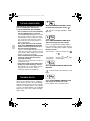
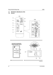
1
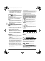
00_CV3PA63363-25Z.fm Page 1 Tuesday, December 3, 2002 6:25 PM
OPERATION MANUAL
Wireless Remote Controller Kit
MODELS:
BRC7E618
English
BRC7E619
Deutsch
Thank you for purchasing this Daikin air conditioner.
Carefully read this operation manual before using the air conditioner.
It will tell you how to use the unit properly and help you if any trouble occurs.
After reading the manual, file it away for future reference.
Vielen Dank für den Kauf einer Klimaanlage von Daikin.
Bitte lesen Sie diese Bedienungsanleitung vor der Inbetriebnahme des Gerätes
gründlich durch. Hier wird erklärt, wie das Gerät richtig eingesetzt wird und was bei
Störungen zu tun ist.
In dieser Anleitung wird nur das Innenaggregat beschrieben.
Verwenden Sie diese Anleitung zusammen mit der Bedienungsanleitung des
Außenaggregats.
Nach dem Lesen der Anleitung legen Sie diese griffbereit zum Nachschlagen auf.
Nous vous remercions pour votre acquisition de ce climatiseur Daikin.
Lisez attentivement ce manuel avant d’utiliser le climatiseur.
Il vous expliquera comment vous servir correctement de l’appareil et vous guidera
en cas de problème.
Lorsque vous aurez lu le manuel, rangez-le afin de pouvoir vous y référer
ultérieurement.
Le agradecemos la compra de este acondicionador de aire Daikin.
Lea cuidadosamente el manual de funcionamiento antes de utilizar el acondicionador
de aire.
Dicho manual le indicará cómo utilizar adecuadamente la máquina y le ayudará en caso
de avería.
Después de leer el manual, consérvelo para consultas futuras.
Français
Español
Italiano
ÅëëçíéêÜ
Nederlands
Portugues
Russian
Taiwanese
Chinese
01_IL_3PA63363-25Z.fm Page 1 Wednesday, December 4, 2002 11:44 AM
La ringraziamo di aver acquistato questo condizionatore d’aria Daikin.
Leggere attentamente questo manuale prima di avviare il condizionatore.
Ciò permetterà di usare correttamente l’unità e di ottenere un aiuto in caso di anomalia
di funzionamento.
Dopo aver letto il manuale, conservarlo in un luogo accessibile per una futura
necessità.
Óáò åu÷áñéóôïýìå ðïõ áãïñÜóáôå ôç óõóêåõÞ êëéìáôéóìïý.
ÄéáâÜóôå ðñïóåêôéêÜ áõôÝò ôéò ïäçãßåò ÷ñÞóçò ðñéí íá ÷ñçóéìïðïéÞóåôå ôç óõóêåõÞ
êëéìáôéóìïý.
Èá óáò ðïõí ðùò èá ÷ñçóéìïðïéÞóåôå óùóôÜ ôç ìïíÜäá êáé èá óáò âïçèÞóïõí áí
åìöáíéóôïýí ðñïâëÞìáôá.
Áöïý äéáâÜóåôå ôéò ïäçãßåò, ÂÜëôå ôéò óôó áñ÷åßï óáò ãéá ìåëëïíôéêÞ áíáöïñÜ.
Wij danken u voor de aankoop van deze Daikin airconditioner.
Lees deze bedrijfshandleiding aandachtig door voordat u de airconditioner gebruikt.
Het omvat uitleg over het correcte gebruik van de unit en biedt hulp in geval een storing
mocht optreden.
Gebruik deze handleding voor verdere raadpleging.
Obrigado pela sua compra deste aparelho de ar condicionado Daikin.
Leia com atenção este manual de operação antes de proceder à utilização do aparelho
de ar condicionado.
Este indicar-lhe-á como deverá utilizar a unidade correctamente e ajudá-lo-á no caso
de surgir qualquer problema.
Depois de ler o manual, guarde-o num local seguro a fim de o poder consultar caso
venha a ser preciso.
Ñïàñèáî çà ïîêóïêó äàííîãî êîíäèöèîíåðà ôèðìû Daikin.
Äî íà÷àëà ðàáîòû ñ êîíäèöèîíåðîì âíèìàòåëüíî èçó÷èòå äàííîå ðóêîâîäñòâî
ïî ýêñïëóàòàöèè.
 íåì èçëàãàþòñÿ ïðàâèëà íàäëåæàùåãî ïîëüçîâàíèÿ óñòðîéñòâîì è
ïðèâîäÿòñÿ ðåêîìåíäàöèè ïîëüçîâàòåëþ ïî ïîèñêó è óñòðàíåíèþ
íåèñïðàâíîñòåé.
Ïîñëå èçó÷åíèÿ ðóêîâîäñòâà ñîõðàíèòå åãî äëÿ îáðàùåíèé â áóäóùåì.
01_IL_3PA63363-25Z.fm Page 2 Wednesday, December 4, 2002 11:44 AM
1-1
1
ON OFF
8
1-2
3
H
M
L
DOWN
10
C
ON OFF
UP
6
TEMP
FAN
H
4
M
L TIME
C
hr.
UP
9
2
11
FAN
hr.
DOWN
13
RESERVE CANCEL
hr.
5
TIMER
12
MODE
15
hr.
TEST
7
SWING
14
16
TEST
TEST
17
1
COOL/HEAT CHANGEOVER
REMOTE CONTROL SWITCH
20
21
24
19
25
18
23
1-3
[1]
2
22
02_IL_3PA63363-25Z.fm Page 13 Wednesday, December 4, 2002 11:44 AM
PRIOR TO USE
This operation manual is exclusively for instructions on how to use the wireless remote controller.
Read also the operation manual attached to the indoor unit for safe usage of the system and
maintenance.
VOR DER INBETRIEBNAHME
Diese Betriebsanleitung enthält ausschließlich Anweisungen über den Gebrauch der drahtlosen
Fernbedienung.
Über die sichere Anwendung und Wartung des Systems, lesen Sie auch die dem lnnenaggregat
beiliegende Bedienungsanleitung.
AVANT LA MISE EN SERVICE
Ce mode d’emploi ne concerne que les instructions d’utilisation de la télécommande sans câble.
Lire également le mode d’emploi joint à l’unité intérieure pour une utilisation et un entretien du
système en toute sécurité.
ANTES DE LA UTILIZACIÓN
Este manual de instrucciones contiene sólo las instrucciones para el uso del control remoto sin
cables.
Lea también el manual de instrucciones que viene con la unidad interior para un uso seguro del
sistema y para su mantenimiento.
PRIMA DELL’USO
Il presente manuale d’uso fornisce esclusivamente istruzioni per l’uso del telecomando via radio.
Per un uso sicuro del sistema e per la sua manutenzione leggere inoltre il manuale d’uso in
dotazione all’unità interna.
ÐÑÉÍ ÁÐÏ ÔÇ ×ÑÇÓÇ
Áõôü ôï åã÷åéñßäéï ëåéôïõñãßáò ðåñéÝ÷åé ìüíï ïäçãßåò ãéá ôç ÷ñÞóç ôïõ áóýñìáôïõ
ôçëå÷åéñéóôçñßïõ.
ÄéáâÜóôå åðßóçò ôï åã÷åéñßäéï ëåéôïõñãßáò ðïõ óõíïäåýåé ôçí åóùôåñéêÞ ìïíÜäá ãéá ôçí áóöáëÞ
÷ñÞóç ôïõ óõóôÞìáôïò êáé ãéá ôç óõíôÞñçóç.
VOOR GEBRUIK
Deze bedieningshandleiding is uitsluitend bedoeld voor gebruik tijdens de instructie over de
werking van de afstandsbediening.
Lees ook de bedieningshandleiding die werd meegeleverd bij de binnenunit voor een veilig
gebruik van het systeem en het onderhoud ervan.
ANTES DE UTILIZAR
O presente manual de funcionamento destina-se exclusivamente para explicar o modo de
utilização do controlo remoto sem fio.
Leia igualmente o manual de funcionamento fornecido com a unidade interior para uma utilização
e manutenção segura do sistema.
ÏÎÄÃÎÒÎÂÊÀ Ê ÈÑÏÎËÜÇÎÂÀÍÈÞ
Äàííîå ðóêîâîäñòâî ïî ýêñïëóàòàöèè ïîñâÿùåíî èñêëþ÷èòåëüíî èíñòðóêòèðîâàíèþ
ðàáîòå ñ áåñïðîâîäíûì óäàëåííûì êîíòðîëëåðîì.
Äëÿ áåçîïàñíîãî èñïîëüçîâàíèÿ è òåõíè÷åñêîãî îáñëóæèâàíèÿ ñèñòåìû îçíàêîìüòåñü
òàêæå ñ ðóêîâîäñòâîì ïî ýêñïëóàòàöèè, ïðèëàãàåìîì ê êîìíàòíîìó áëîêó.
[2]
04_EN_3PA63363-25Z.fm Page 1 Wednesday, December 4, 2002 10:10 AM
CONTENTS
ILLUSTRATION............................... [1]
PRIOR TO USE .............................. [2]
1 SAFETY CONSIDERATIONS .......... 1
2 NAMES AND FUNCTIONS OF THE
OPERATING SECTION.................... 2
3 HANDLING FOR WIRELESS
REMOTE CONTROLLER ................. 3
4 OPERATION RANGE ....................... 4
5 OPERATION PROCEDURE............. 5
6 NOT MALFUNCTION OF THE
AIR CONDITIONER........................ 10
7 HOW TO DIAGNOSE
TROUBLE SPOTS.......................... 10
1. SAFETY
CONSIDERATIONS
Read the following cautions carefully and
use your equipment properly.
There are three kinds of safety cautions and
tips listed here as follows:
WARNING ....... Improper handling can
lead to such serious consequences as death or
severe injury.
CAUTION ........ Improper handling can
lead to injury or damage.
It could also have serious
consequences under
certain conditions.
NOTE
........ These instructions will
ensure proper use of the
equipment.
Be sure to follow these important safety cautions.
Keep these warning sheets handy so that
you can refer to them if needed.
Also, if this equipment is transferred to a new
user, make sure to hand over this user’s manual to the new user.
English
WARNING
Do not expose yourself directly to the
cool air currents too long nor allow the
air in the room to become too cold.
Doing so may make you feel sick or damage your health.
If you detect any abnormality (such as the
smell of fire), turn off the power and contact your dealer for instructions.
If you keep using the air conditioner
under these conditions, it will eventually
break down, and could cause electric
shocks or catch fire.
Ask your dealer to install your equipment.
Improper installation could cause water
leakage, electric shocks or fire.
Ask your dealer to perform servicing or
repairs whenever necessary.
Improper servicing or repairs could cause
water leakage, electric shocks or fire.
Do not stick your fingers or any other
objects into the air inlet, air outlet or air
direction vanes during operation.
The high-speed fan is dangerous and
could cause injury.
Ask your dealer to remove and reinstall
your equipment whenever necessary.
Improper installation could cause water
leakage, electric shocks or fire.
CAUTION
Do not use the air conditioner for purposes other than air conditioning.
Do not use the air conditioner for special
purposes such as preserving or protecting
food, animals, plants, precision machinery
or works of art, since the quality of such
items could be adversely affected.
When using the air conditioner with other
heating equipment, ventilate the room
from time to time.
Inadequate ventilation could cause an
oxygen shortage.
Do not expose your pets or plants to
the air current.
They may be adversely affected.
Do not operate the air conditioner with
a wet hand.
Otherwise, you could receive an electric
shock.
1
04_EN_3PA63363-25Z.fm Page 2 Wednesday, December 4, 2002 10:10 AM
Do not place any burning appliance in the
air current from the air conditioner, since
such appliance may suffer incomplete
combustion.
Never place nor use any inflammable
sprays near the air conditioner, since
such sprays could cause a fire.
The batteries must be removed from
the appliance before it is scrapped
and they are disposed of safely.
7
8
9
2. NAMES AND FUNCTIONS
OF THE OPERATING SECTION (Fig. 1, 2)
10
DISPLAY “
”
(SIGNAL TRANSMISSION)
1
This lights up when a signal is being
transmitted.
11
DISPLAY “ ” “ ” “
”“
“ ” (OPERATION MODE)
”
2 This display shows the current OPERATION MODE. For cooling only type,
“
” (Auto) and “ ” (Heating) are
not installed.
3
DISPLAY “
H
M
L
C
” (SET TEMPERATURE)
12
13
14
15
This display shows the set temperature.
hr.
DISPLAY “ hr.
”
(PROGRAMMED
TIME)
4
This display shows PROGRAMMED
TIME of the system start or stop.
5
DISPLAY “
” (AIR FLOW FLAP)
Refer to page 6.
6
DISPLAY “
”“
” (FAN SPEED)
The display shows the set fan speed.
16
17
18
2
TEST ”
DISPLAY “
(INSPECTION/ TEST OPERATION)
When the INSPECTION/TEST OPERATION BUTTON is pressed, the display
shows the system mode is in.
ON/OFF BUTTON
Press the button and the system will
start. Press the button again and the
system will stop.
FAN SPEED CONTROL BUTTON
Press this button to select the fan
speed, HIGH or LOW, of your choice.
TEMPERATURE SETTING BUTTON
Use this button for SETTING TEMPERATURE (Operates with the front cover
of the remote controller closed.)
PROGRAMMING TIMER BUTTON
Use this button for programming
“START and/or STOP” time. (Operates
with the front cover of the remote controller opened.)
TIMER MODE START/STOP BUTTON
Refer to page 7.
TIMER RESERVE/CANCEL BUTTON
Refer to page 8.
AIR FLOW DIRECTION ADJUST BUTTON
Refer to page 6.
OPERATION MODE SELECTOR BUTTON
Press this button to select OPERATION
MODE.
FILTER SIGN RESET BUTTON
Refer to the section of MAINTENANCE
in the operation manual attached to the
indoor unit.
INSPECTION/TEST OPERATION
BUTTON
This button is used only by qualified
service persons for maintenance
purposes.
EMERGENCY OPERATION SWITCH
This switch is readily used if the remote
controller does not work.
English
04_EN_3PA63363-25Z.fm Page 3 Wednesday, December 4, 2002 10:10 AM
19
20
21
22
23
24
RECEIVER
This receives the signals from the
remote controller.
OPERATING INDICATOR LAMP (Red)
This lamp stays lit while the air
conditioner runs. It flashes when the
unit is in trouble.
TIMER INDICATOR LAMP (Green)
This lamp stays lit while the timer is set.
AIR FILTER CLEANING TIME
INDICATOR LAMP (Red)
Lights up when it is time to clean the air
filter.
DEFROST LAMP (Orange)
Lights up when the defrosting operation has started. (For cooling only type
this lamp does not turn on.)
FAN/AIR CONDITIONING SELECTOR
SWITCH
Set the switch to “
” (FAN) for FAN
and “
” (A/C) for HEAT or COOL.
COOL/HEAT CHANGEOVER SWITCH
25 Set the switch to “
COOL and “
” (COOL) for
” (HEAT) for HEAT.
NOTES
• For the sake of explanation, all indications are shown on the display in Figure 1
contrary to actual running situations.
• Fig. 1-2 shows the remote controller with
the front cover opened.
• Fig. 1-3 shows this remote controller can
be used in conjunction with the one provided with the VRV system.
• If the air filter cleaning time indicator lamp
lights up, clean the air filter as explained
in the operation manual provided with the
indoor unit.
After cleaning and reinstalling the air filter, press the filter sign reset button on
the remote controller. The air filter cleaning time indicator lamp on the receiver will
go out.
• The Defrost Lamp will flash when the power
is turned on. This is not a malfunction.
English
3. HANDLING FOR
WIRELESS REMOTE
CONTROLLER
Precautions in handling remote controller
Direct the transmitting part of the remote
controller to the receiving part of the air
conditioner.
If something blocks the transmitting and receiving path of the indoor unit and the remote controller as curtains, it will not operate.
2 short beeps
from the receiver
indicates that the
transmission is
properly done.
Transmitting distance is approximately 7 m.
Do not drop or get it wet.
It may be damaged.
Never press the button of the remote controller with a hard, pointed object.
The remote controller may be damaged.
Installation site
• It is possible that signals will not be received
in rooms that have electronic fluorescent
lighting. Please consult with the salesman
before buying new fluorescent lights.
• If the remote controller operated some
other electrical apparatus, move that
machine away or consult your dealer.
Placing the remote controller in the
remote controller holder
Install the remote controller holder to a wall
or a pillar with the attached screw. (Make
sure it transmits)
3
04_EN_3PA63363-25Z.fm Page 4 Wednesday, December 4, 2002 10:10 AM
IN THE CASE OF CENTRALIZED
CONTROL SYSTEM
Placing the remote
controller
Removing the
remote controller
Slide from above
Pull it upward
If the indoor unit is under centralized control, it is
necessary to switch the remote controller’s setting.
In this case, contact your DAIKIN dealer.
4. OPERATION RANGE
VRV System
See the operation manual provided with the
air conditioner.
Split System
Remote
controller
holder
How to put the dry batteries
If the temperature or the humidity is beyond the
following conditions, safety devices may work
and the air conditioner may not operate, or
sometimes, water may drop from the indoor unit.
COOLING
OUTDOOR
UNIT
(1) Remove the back cover
of the remote controller
to the direction pointed
by the arrow mark.
(2) Put the batteries
Use two LR03<IEC>
dry cell batteries. Put
dry batteries correctly
to fit their (+) and (–).
(3) Close the cover
COOLING
R71
ONLY
RP71
TYPE
HEAT
PUMP
TYPE
RY71
RYP71
[°C]
INDOOR
TEMPERA- HUMIDTURE
ITY
D
20 to 35
B
80% or
below
W
14 to 25
B
D
18 to 35
B
80% or
below
W
12 to 25
B
HEATING
When to change batteries
Under normal use, batteries last about a
year. However, change them whenever the
indoor unit doesn’t respond or responds
slowly to commands, or if the display
becomes dark.
4
D
– 5 to 46
B
RY71
RYP71
INDOOR
OUTDOOR TEMTEMPERATURE
PERATURE
D
B
15 to 27
[CAUTIONS]
• Replace all batteries at the same time, do
not use new and old batteries intermixed.
• In case the remote controller is not used
for a long time take out all batteries in order
to prevent liquid leak of the battery.
D
21 to 46
B
[°C]
OUTDOOR
UNIT
HEAT
PUMP
TYPE
OUTDOOR
TEMPERATURE
D
B
W
B
– 9 to 21
– 10 to 15
DB: Dry bulb temperature
WB: Wet bulb temperature
The setting temperature range of the remote
controller is 16°C to 32°C.
English
04_EN_3PA63363-25Z.fm Page 5 Wednesday, December 4, 2002 10:10 AM
5. OPERATION PROCEDURE
Refer to figure 1 on page [1]
• Operating procedure varies with heat
pump type and cooling only type. Contact
your Daikin dealer to confirm your system
type.
• To protect the unit, turn on the main power
switch 6 hours before operation.
• If the main power supply is turned off during operation, operation will restart automatically after the power turns back on
again.
COOLING, HEATING, AUTOMATIC,
FAN, AND PROGRAM DRY
OPERATION
Operate in the following order.
• AUTOMATIC OPERATION can be
selected only by Heat pump split system or
Heat recovery VRV system.
• For cooling only type, “COOLING”, and
“FAN” and “DRY”operation are able to
select.
〈〈FOR
SYSTEMS WITHOUT COOL/
〈〈
HEAT CHANGEOVER REMOTE
〉〉
CONTROL SWITCH〉〉
MODE
OPERATION lamp lights up or goes off and
the system starts or stops OPERATION.
NOTE
• Do not turn OFF power immediately after
the unit stops. Then, wait no less than
5 minutes.
Water is leaking or there is something else
wrong with the unit.
〈〈FOR
SYSTEMS WITH COOL/HEAT
〈〈
CHANGEOVER REMOTE CONTROL
〉〉
SWITCH〉〉
OPERATION MODE
SELECTOR
(1) Select OPERATION MODE with the
COOL/HEAT CHANGEOVER REMOTE
CONTROL SWITCH as follows.
Press OPERATION MODE SELECTOR
button several times and select the
OPERATION MODE of your choice as
follows.
”
”
”
• In this operation mode, COOL/HEAT
changeover is automatically conducted.
FAN OPERATION .............................. “
DRY OPERATION ............................. “
ON/OFF
Press ON/OFF button
1
OPERATION MODE
SELECTOR
COOLING OPERATION .................... “
HEATING OPERATION ..................... “
AUTOMATIC OPERATION ................ “
2
ON OFF
Refer to figure 1-1,3 on page [1]
Refer to figure 1-1, 2 on page [1]
1
• The function of this program is to
decrease the humidity in your room with
the minimum temperature decrease.
• Micro computer automatically
determines TEMPERATURE and FAN
SPEED.
• This system does not go into operation if
the room temperature is below 16°C.
COOLING OPERATION ............. “
”
HEATING OPERATION .............. “
”
FAN OPERATION....................... “
”
DRY OPERATION ...................... “
”
”
”
• See “FOR SYSTEM WITHOUT COOL/
HEAT CHANGEOVER REMOTE CONTROL SWITCH” for details on dry operation.
English
5
04_EN_3PA63363-25Z.fm Page 6 Wednesday, December 4, 2002 10:10 AM
(2) Press OPERATION MODE SELECTOR
button several times and select “ ”
(This operation is only available during
dry operation.)
2
For programming TEMPERATURE, FAN
SPEED and AIR FLOW DIRECTION, follow
the procedure shown below.
DOWN
ON OFF
ON/OFF
Press ON/OFF button
OPERATION lamp lights up or goes off and
the system starts or stops OPERATION.
NOTE
• Do not turn OFF power immediately after
the unit stops. Then, wait no less than
5 minutes.
Water is leaking or there is something else
wrong with the unit.
[EXPLANATION OF HEATING OPERATION]
DEFROST OPERATION
• As the frost on the coil of an outdoor unit
increase, heating effect decreases and the
system goes into DEFROST OPERATION.
• The fan operation stops and the
DEFROST lamp of the indoor unit goes on.
After 6 to 8 minutes (maximum 10 minutes) of DEFROST OPERATION, the system returns to HEATING OPERATION.
Heating capacity & Outdoor air
temperature
• Heating capacity drops as outdoor air temperature lowers. If feeling cold, use
another heater at the same time as this air
conditioner.
• Hot air is circulated to warm the room. It will
take some time from when the air conditioner
is first started until the entire room becomes
warm. The internal fan automatically turns at
low speed until the air conditioner reaches a
certain temperature on the inside. In this situation, all you can do is wait.
• If hot air accumulates on the ceiling and
feet are left feeling cold, it is recommended
to use a circulator. For details, contact the
place of purchase.
6
ADJUSTMENT
TEMPERATURE SETTING
UP
Press TEMPERATURE SETTING button
and program the setting temperature.
UP
Each time this button is pressed,
setting temperature rises 1°C.
DOWN
Each time this button is pressed,
setting temperature lowers 1°C.
In case of automatic operation
UP
DOWN
Each time this button is pressed,
setting temperature shifts to “H”
side.
Each time this button is pressed,
setting temperature shifts to “L”
side.
[°C]
Setting
temperature
H
M
L
25
23
22
21
19
• The setting is impossible for fan operation.
NOTE
• The setting temperature range of the
remote controller is 16°C to 32°C.
FAN
FAN SPEED CONTROL
Press FAN SPEED CONTROL button.
High or Low fan speed can be selected.
The microchip may sometimes control the
fan speed in order to protect the unit.
SWING
AIR FLOW DIRECTION
ADJUST
Press the AIR FLOW DIRECTION
ADJUST button to select the air direction as shown below.
English
04_EN_3PA63363-25Z.fm Page 7 Wednesday, December 4, 2002 10:10 AM
DISPLAY appears and the
air flow direction continuously varies. (Automatic
swing setting)
Press AIR FLOW DIRECTION ADJUST button to
select the air direction of
your choice.
DISPLAY vanishes the air
flow direction is fixed
(Fixed air flow direction
setting).
Adjusting left/right air flow direction
Angle the flaps to the left/
right from the knob, as
wanted or as needed to air
condition the room.
NOTE
• Stop flaps from swinging
before trying to angle
them. Working while the
flaps are moving may get your fingers
pinched.
MOVEMENT OF THE AIR FLOW FLAP
For the following conditions, micro computer
controls the air flow direction so it may be
different from the display.
Operation
mode
Cooling
• When operating continuously at
downward air
flow direction
Operation
conditions
English
Heating
• When room
temperature is
higher than the
set temperature
• At defrost
operation
(The flaps blow
horizontally to
avoid blowing
cold air directly
on the occupants
of the room.)
NOTE
• If you try cooling or programmed drying,
while the flaps are facing downward, air
flow direction may change unexpectedly.
There is nothing wrong with the equipment.
This serves to prevent dew formed on parts
in the air discharge outlet from dripping.
• Operation mode includes automatic
operation.
PROGRAM TIMER OPERATION
Operate in the following order.
• The timer is operated in the following two ways.
Programming the stop time (
)
.... The system stops
operating after the set time has elapsed.
Programming the start time (
)
.... The system starts
operating after the set time has elapsed.
• The timer can be programmed a maximum
of 72 hours.
• The start and the stop time can be simultaneously programmed.
1
TIMER
TIMER MODE START/
STOP
Press the TIMER MODE START/STOP
button several times and select the
mode on the display.
The display flashes.
For setting the timer stop .... “
For setting the timer start .... “
2
”
”
PROGRAMMING TIME
UP
DOWN
Press the PROGRAMMING TIME button and set the time for stopping or
starting the system.
UP
When this button is pressed, the
time advances by 1 hour.
DOWN
When this button is pressed, the
time goes backward by 1 hour.
7
04_EN_3PA63363-25Z.fm Page 8 Wednesday, December 4, 2002 10:10 AM
TIMER RESERVE
RESERVE
3
Outdoor unit
Press the TIMER RESERVE button.
The timer setting procedure ends.
The display changes from flashing light to a
constant light.
CANCEL
4
Indoor unit
TIMER CANCEL
Press the TIMER OFF button to cancel
programming. The display vanishes.
For example.
ON OFF
TEMP
TIME
C
UP
FAN
DOWN
RESERVE CANCEL
hr.
TIMER
hr.
MODE
When the timer is
programmed to stop
the system after 3
hours and start the
system after 4
hours, the system
will stop after 3
hours and then 1
hour later the system will start.
One of these remote controllers needs
to be designated as the master remote
controller.
For Heat recovery system
When one BS unit is connected with several
indoor units.
Outdoor unit
BS unit
Indoor unit
NOTE
• After the timer is programmed, the display
shows the remaining time.
HOW TO SET MASTER
REMOTE CONTROLLER
(For VRV system)
• When the system is installed as shown
below, it is necessary to designate the
master remote controller.
For Heat pump system
When one outdoor unit is connected with
several indoor units.
8
One of these remote controllers needs
to be designated as the master remote
controller.
• Only the master remote controller can
select HEATING, COOLING or
AUTOMATIC (only Heat recovery system)
OPERATION.
When the indoor unit with master remote
controller is set to “COOL”, you can switch
over operation mode between “FAN”, “DRY”
and “COOL”.
When the indoor unit with master remote controller is set to “HEAT”, you can switch over
operation mode between “FAN” and “HEAT”.
When the indoor unit with master remote
controller is set to “FAN”, you cannot switch
operation mode.
English
04_EN_3PA63363-25Z.fm Page 9 Wednesday, December 4, 2002 10:10 AM
When attempting settings than that
consented above, a “peep” is emitted as a
warning.
Only with Heat recovery system, you can set
the indoor unit to AUTOMATIC. Attempting to
do so, a “peep” will be emitted as a warning.
1 2
How to designate the master remote
controller
Operate in the following order.
1
MODE
Continuously press the OPERATION
MODE SELECTOR button for 4 seconds.
The displays showing “
” of all slave indoor
unit connected to the same outdoor unit or
BS unit flash.
2
MODE
Press the OPERATION MODE SELECTOR button to the indoor unit that you
wish to designate as the master remote
controller. Then designation is completed. This indoor unit is designated
as the master remote controller and
the display showing “ ” vanishes.
• To change settings, repeat steps 1 and 2 .
EMERGENCY OPERATION
When the remote controller does not work
due to battery failure or the absence thereof,
use this switch which is located beside the
discharge grille on the main unit. When the
remote controller does not work, but the
battery low indicator on it is not lit, contact
your dealer.
[START]
1
To press the emergency operation switch.
The machine runs in the previous mode.
The system operates with the previously set
air flow direction.
English
[STOP]
2
Press the EMERGENCY OPERATION switch again.
PRECAUTIONS FOR GROUP
CONTROL SYSTEM OR TWO
REMOTE CONTROLLER
CONTROL SYSTEM
This system provides two other control
systems beside individual control (one
remote controller controls one indoor unit)
system. Confirm the following if your unit is of
the following control system type.
Group control system
One remote controller controls up to 16
indoor units.
All indoor units are equally set.
Two remote controller control system
Two remote controllers control one indoor
unit. (In case of group control system, one
group of indoor units)
The unit follows individual operation.
NOTES
• Cannot have two remote controller control
system with only wireless remote controllers. (It will be a two remote controller control system having one wired and one
wireless remote controllers.)
• Under two remote controller control system, wireless remote controller cannot
control timer operation.
• Only the operating indicator lamp out of 3 other
lamps on the indoor unit display functions.
NOTE
• Contact your Daikin dealer in case of
changing the combination or setting of
group control and two remote controller
control systems.
9
04_EN_3PA63363-25Z.fm Page 10 Wednesday, December 4, 2002 10:10 AM
6. NOT MALFUNCTION OF
THE AIR CONDITIONER
TEST
1
The following symptoms do not indicate air conditioner malfunction
Press the INSPECTION/TEST button
to select the inspection mode “ ”.
I. THE SYSTEM DOES NOT OPERATE
• The system does not restart immediately
after the ON/OFF button is pressed.
If the OPERATION lamp lights, the system
is in normal condition. It does not restart
immediately because a safety device operates to prevent overload of the system.
After 3 minutes, the system will turn on
again automatically.
• The system does not restart immediately when TEMPERATURE SETTING
button is returned to the former position after pushing the button.
It does not restart immediately because a
safety device operates to prevent overload
of the system. After 3 minutes, the system
will turn on again automatically.
• If the reception beep is rapidly repeated
3 times (It sounds only twice when
operating normally.)
Control is set to the optional controller for
centralized control.
• If the defrost lamp on the indoor unit’s
display is lit when heating is started.
This indication is to warn against cold air
being blown from the unit. There is
nothing wrong with the equipment.
“
” appears on display and blinks. “UNIT”
lights up.
2
UP
DOWN
Press PROGRAMMING TIMER BUTTON and change the unit number.
Press to change the unit number until the
indoor unit beeps and perform the following
operation according to the number of beeps.
Number of beeps
3 short beeps .....Perform all steps from 3
to 6 .
1 short beep .......Perform 3 and 6 steps
1 long beep ........Normal state
3
MODE
Press OPERATION MODE SELECTOR
BUTTON
“
” on the left-hand of the malfunction code
blinks.
7. HOW TO DIAGNOSE
TROUBLE SPOTS
I. EMERGENCY STOP
When the air conditioner stops in emergency,
the run lamp on the indoor unit starts blinking.
Take the following steps yourself to read the
malfunction code that appears on the display.
Contact your dealer with this code. It will help
pinpoint the cause of the trouble, speeding
up the repair.
10
4
UP
DOWN
Press PROGRAMMING TIMER BUTTON
and change the malfunction code.
Press until the indoor unit beeps twice.
English
04_EN_3PA63363-25Z.fm Page 11 Wednesday, December 4, 2002 10:10 AM
5
MODE
Press OPERATION MODE SELECTOR
BUTTON
• Check if there are batteries in the
remote controller. Place the batteries.
• Check if the indoor unit number and
wireless remote controller number are
equal.
“
” on the right-hand of the malfunction
code blinks.
6
UP
DOWN
Press PROGRAMMING TIMER BUTTON
and change the malfunction code.
Press until the indoor unit makes a long
beep.
The malfunction code is fixed when the
indoor unit makes a long beep.
7
MODE
Number
Reset of the display
Press OPERATION MODE SELECTOR
BUTTON to get the display back to the
normal state.
ON OFF
24
6 TEMP
TIME
UP
CODE
FAN
UNIT NO.
DOWN
24
6
RESERVE CANCEL
TIMER
MODE
35
7
SWING
/TEST
1
II. IN CASE BESIDES EMERGENCY STOP
1. The unit does not operate at all.
• Check if the receiver is exposed of
sunlight or strong light. Keep receiver
away from light.
English
Number
Operate the indoor unit with the remote controller of the same number.
Signal transmitted from a remote controller of
a different number cannot be accepted. (If
the number is not mentioned, it is considered
as “1”)
2. The system operates but it does not
sufficiently cool or heat.
• If the set temperature is not proper.
• If the FAN SPEED is set to LOW
SPEED.
• If the air flow angle is not proper.
Contact the place of purchase in the following case.
WARNING
When you detect a burning odor, shut
OFF power immediately and contact the
place of purchase. Using the equipment
in anything but proper working condition
can result in equipment damage, electric
shock and/or fire.
11
04_EN_3PA63363-25Z.fm Page 12 Wednesday, December 4, 2002 10:10 AM
[Trouble]
The RUN lamp of the indoor unit is flashing
and the unit does not work at all.
Malfunction Code
Unit No. which
sensed trouble
ON OFF
TEMP
TIME
UP
CODE
FAN
UNIT NO.
DOWN
RESERVE CANCEL
TIMER
MODE
SWING
/TEST
INSPECTION
display
[Remedial action]
Check the malfunction code (A1 - UF) on the
remote controller and contact the place of
purchase. (See page 10.)
12
English
00_CV3PA63363-25Z.fm Page 2 Tuesday, December 3, 2002 6:25 PM
3PA63363-25Z EM01A186A (0212)
HT