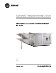
1
FHP 560/583 USERS GUIDE 8733 806 168 641-242 Table of Contents I FHP 560/583 ................................. 1 ZONE CONTROL ................................. 18 THE ZONE CONTROLLER ...................... 4 Set-points Management .............................................. 19 Zone Temperature Limits ........................................... 19 Remote Temperature Limits ....................................... 19 SPECIFICATIONS ................................. 5 FAN MODE ......................................... 20 BATTERY REPLACEMENT ..................... 9 Start / Stop Fan ........................................................... 20 Variable Frequency Drive (VFD) Fan ........................ 20 Fan Operation ............................................................. 20 Fan Override ............................................................... 21 VFD Control ............................................................... 21 Fan Operation during Smoke Event ............................ 21 Fan History Statistics .................................................. 22 Mixed Air Analog Output ........................................... 22 LONWORKS® CARD OPTION............. 10 INPUT-5 FUNCTIONALITY ................ 22 CONTROLLER HARDWARE FEATURES . 6 LED Indicators ..............................................................6 DIP and Rotary Switches...............................................7 Jumpers and settings ......................................................8 WATER TO AIR OPERATION .............. 11 General Description ....................................................... 11 Key Features and Benefits ............................................. 11 Filter Status (DFS) ...................................................... 23 Damper End Switch (DES) ......................................... 23 Differential Pressure Switch (DPS) ............................ 24 Secondary Condensation Drain Pan (SDP) ................. 24 Smoke Detector Status (SDS) ..................................... 25 Supply Fan Status (FSS) ............................................. 25 Valve Status (VES) ..................................................... 25 Inputs .............................................................................. 12 HEATING & COOLING OPERATION ... 26 Outputs ............................................................................ 12 Control & Status Parameters and Alarms ................... 12 Control ......................................................................... 12 Status ........................................................................... 13 Alarms ......................................................................... 13 Heating ........................................................................ 26 Cooling ....................................................................... 26 HGRH Start/Stop (On/Off) ......................................... 26 Dedicated Outside Air ................................................ 27 Reversing Valve Operation ......................................... 27 Discharge Air Temperature (DAT) Sensor ................. 28 SEQUENCE OF OPERATION................ 14 High Discharge Air Temperature Condition (Cooling) ......................................................................................... 28 Control Source (Run Conditions) ................................ 14 External Control Source .............................................. 14 Internal Control Source (Keypad) ............................... 15 Low Discharge Air Temperature Condition (Heating) ......................................................................................... 28 UNIT MODE ........................................ 16 WATER TO WATER OPERATION ........ 36 Cooling Only ............................................................... 16 Auxiliary Heating ........................................................ 16 Heat Pump ................................................................... 16 Heat Pump with Aux Heat ........................................... 16 Heat Pump with Hot Gas Re-Heat ............................... 16 Cooling Only with Hot Gas Re-Heat ........................... 17 TEMPERATURE SENSOR SELECTION . 17 GENERAL DESCRIPTION ................... 36 Inputs .......................................................................... 36 Outputs ........................................................................ 36 CONTROL & STATUS PARAMETERS AND ALARMS ..................................... 37 Status and Control ....................................................... 37 Alarms......................................................................... 37 2 SEQUENCE OF OPERATION................ 38 Run Conditions: ............................................................. 38 Occupied Mode ........................................................... 38 Unoccupied Mode (night setback):.............................. 38 Auto Changeover Mode .............................................. 38 Digital Input Mode ...................................................... 39 BAS Mode ................................................................... 39 Leaving Low Temp:.................................................... 41 Leaving Sensor Failure: .............................................. 41 NOTES ........................................................................... 44 Lead - Lag Compressor operation ................................ 40 Compressor 1 Runtime: ............................................... 40 Compressor 2 Runtime: ............................................... 40 Pump Control (optional) ................................................ 40 Pump Runtime Alarm: ................................................. 40 Load Water (Entering) Temperature: ......................... 41 Load High Temp: ........................................................ 41 Load Low Temp: ......................................................... 41 Load Sensor Failure: ................................................... 41 Source Water (Leaving) Temperature: ........................ 41 Leaving High Temp: ................................................... 41 3 The Zone Controller The Zone control board, also known as DDC Output (AO) plug above the Binary Output (Direct Digital Controller) and shown in (BO) plug. figure 1, is used in most configure-to-order The controller is programmed from the applications. supplier or at the factory with software It is BACnet® native, which makes it flexible versions that suit the different applications and easy to integrate into existing Building FHP offers. User settings such as the time Automation and test and balance set points should be Systems (BAS). The main difference between the FHP 560 and the set up during the installation FHP 583 is that the 538 has an Analog commissioning process at the job site. and Figure 1 – FHP 560 Controller 4 Specifications Power: 24VAC ± 10%, 50-60Hz, 20VA power consumption (Single Class II 70VA or 100VA option available) Physical: Rugged plastic housing protects circuitry. Environmental Operating Range: 40° to 130°F (-17.8° to 54.4°C); 10 to 90% relative humidity, non-condensing Digital Outputs: Five binary outputs: Type A relay contacts rated at 1A resistive @ 24VAC; configured as dry contact, normally open. Universal Inputs: 6 to 8 universal inputs. Inputs 1 and 2 are configurable for 0-5VDC, 10K ohm thermistor, or dry contact; inputs 3 and 4 support thermistor or dry contact only; inputs 5 and 6 support thermistor, dry contact, or LogiStat. Inputs 7 and 8 are used for 1-10K adjustment pots or dry contacts (FHP 583 only). Standard Communication: Comm. Port: 3-pin port configurable for ARC156 (BACnet-over-ARC156) or EIA-485 communications (BACnet MS/TP, Modbus RTU, or N2). Ports: Rnet Port: 4-pin port for interface with remote mounted BACview6 or RS sensors Local Access Port: For local communication with a laptop computer running WebCTRL or for communication with a BACview6. BACnet Support: Advanced Application Controller (B-AAC), as defined in BACnet 135-2001 Annex L Communication Ports Status Indication: Visual (LED) status of network communication, run status, errors, power, and all digital outputs Battery: Lithium 3V coin cell battery, CR2032, provides a minimum of 10,000 hours of data retention (based on installation in conditioned space) during power outages. Protection: Surge and transient protection circuitry for power and communications. Listed by: FCC Part 15 - Subpart B - Class A. Pending listings at the time of publishing this document: UL 916 (PAZX), cUL C22.2 No. 205-M1983 (PAZX7), CE (1997). Weight: 0.6 Lbs. (0.27 Kg). Overall Dimensions (W x H x D): 5-1/16” (129mm) x 5-11/16” (144mm) x 1-1/2” (38mm) (recommended panel depth). Mounting Hole Dimensions: Two mounting holes located center line of controller with 5-9/16” (141mm) vertical spacing. 5 Controller Hardware Features LED Indicators The DDC is equipped with three sets of LED banks that help the user diagnose problems and/or identify normal operation. The first bank of LEDs is located in the upper left-hand corner as shown in Figure 2. Figure 2 - Network LEDs The LEDs (Rx and Tx) flash repeatedly when the controller is communicating with the network. The second bank is located on the upper right hand corner of the controller as shown in Figure 3. The top LED (POWER) is normally lit green to indicate that the controller is powered. The middle LED (RUN) represents the “heart beat” of the Figure 3 - Power LEDs controller and flashes green during normal operation. The bottom LED (ERROR) is usually off during normal operation and only lights up red when the controller detects an error. In addition, when downloading new or modified versions of software these LEDs will flash on and off, indicating new files are being written to the controller’s non-volatile memory. Figure 4 – Digital Output LEDs 6 The third and final bank of LEDs are located at the bottom right corner of the controller, as shown in Figure 4, and indicate whether each of the five (5) Binary or Digital Outputs (BO) are energized or not. DIP and Rotary Switches Figure 5 – Controller Address Rotary DIP switch Two sets of switches can be found on the controllers; they must be set properly to I MP O R T A N T : allow correct operation of the unit. Controllers must be addressed correctly The first set is a bank of rotary switches for multiple units to (shown in Figure 5), located on the top, left- work on a network. hand corner. These switches are used to set a unique address for the controller when it is Figure 6 – Rotary switches connected to a network. The address is represented by a two-digit number (00-99) setting with the rotary switches; the top rotary representing the tens digit and the bottom rotary representing the ones digit (as shown in Figure 6). The second set of switches is the bank of DIP switches located on the top, right-hand corner of the controller. The purpose of this Figure 7 – DIP Switches switch bank is two-fold: 7 (1) SW1 and SW2 set the baud rate of the communications port on the controller: BAUD RATE 9600 19.2K 38.4K 76.8K (2) SW3 supported and SW1 Off Off On On SW2 Off On Off On SW4 protocols enable on the BACnet® MS/TP • Thermistor • Dry Contact however, there may be cases where a different controller; SW3 SW4 Off On Off On Off Off On On particular sensor is required by the customer after it leaves the factory. It’s therefore important for the installer to understand jumper settings and their relationship with unit configuration and operation. Figure 10 shows the location of the jumpers on the controller. 4 N2 Modbus Option Card 0-5 VDC Analog Input FHP configures most switches in-house; additional hardware is needed for LonTalk®. PROTOCOLS • The 3 Typical DIP switch for LonTalk® (Option Card) is shown in figure 11. LonTalk® card must be installed. 1 2 Jumpers set up will be ON Jumpers and settings I MP O R T A N T : cover under the jumper section. Figure 8 - LonTalk® DIP Settings The controllers come equipped with a series of jumpers which allow different types of inputs to be terminated in a particular point. Most inputs (IN) allow thermistor or dry contact input devices to be terminated in them, however, IN1 and IN2 can be used as analog or digital input points and their available options are as follows: EIA-485 BACnet over ARC156 Figure 9 - Jumper setting for LonTalk® only. 8 4. Use needle nose pliers to remove the old battery and insert the new one. 5. Connect network cable and verify Rx and Tx LEDs are flashing. 6. Check with BAS operator for DDC functionality 7. After the battery is replaced, if additional service on the unit is required follow OSHA standards. In some cases a controller might experience Figure 10 - Jumper Settings RAM memory losses due to: • “Shorting” across the battery (Lithium 3V, CR2032), • Battery Replacement Low Voltage on the controller (10%/+10% on 24vac input), or The 3V battery mounted on the controller may need to be replaced over time. To replace the battery do the following: 1. Close all panels that expose high • Hi Voltage on the controller Network Cable (RS485) Resetting the controller by recycling the battery power usually resolves this problem. To do this: remove the 24VAC Unit Power voltage from the unit. 2. Disconnect the network plug Figure 2 from the controller for about 5-10 seconds 3. Keep minimum; pull the battery out; replace the 24VAC Figure4. Power connected battery and reconnect power back to the controller. 9 LonWorks® card option LonWorks® is a network platform that allows any facility or to integrate sub-systems using a common system architecture and infrastructure. This platform provides fully open operability of the components within a system or sub-system, this enables the facility owner to utilize different vendors and still have the capability of integrating their system into one single server or front end. The LON card option is available for both controllers. The LON card connects to the option card port as shown in figure 11. Figure 11 - LonTalk® Card – 641-237 10 Water to Air Operation General Description The Heat Pump Factory mounted FHP560 or 583 controllers are factory configured with the Water to Air application program and factory installed in the unit to be job site ready to run. The unit will operate in a 100% stand-alone control mode or connect to a Building Automation System (BAS) using open protocols including BACnet® (ARCNET and MS/TP), Modbus RTU, N2 or LonWorks® (additional network interface board required for LonWorks® option). The point mapping to all of these protocols is available in www.fhp-mfh.com and can be pre-set so that the desired protocol and baud rates can be easily field-selected and commissioned without the need for any additional downloads or technical assistance. The FHP controllers also support communications for intelligent RS Room sensors and BACview keypad/display panels. Key Features and Benefits • I/O point count: 5 Digital outputs, 6 Universal inputs, and 3 Analog outputs (FHP 583 only) • Powerful high speed microprocessor with 1MB Flash memory and 1MB of battery-backed RAM • Built-in protocol support: BACnet® (ARCNET and MS/TP), Modbus, N2 and LonWorks® (additional network interface board required for LonWorks® option) • Built-in local access support: BACview6 keyboard/display and Intelligent RS Room sensors • On-board lithium battery holds controller time clock settings • Program archived in non-volatile memory allows unit to be ready after long periods of power outages. • Parameter settings archived in non-volatile memory allows unit configuration to be available after long periods of power outages. 11 Inputs • RS Room temperature sensor (Rnet) • RS Room temperature sensor Set point adjust (Rnet) • RS Room temperature sensor Occupancy override (Rnet) • Discharge air temperature sensor • Leaving water temperature sensor • Unit Protection module (UPM) Alarm codes (7 safety shutdown alarms) • Unit Filter status (optional) • Unit Enable manual control (optional DI Enable) Outputs • Unit blower control • Reversing Valve • Cooling Stage 1 • Cooling Stage 2 (Comp 2 Circuit or Comp1 Stage 2) • Humidity control output (optional Hot gas re-heat) • Auxiliary/Emergency Heating Stage (optional Electric Heat) Control & Status Parameters and Alarms Control • BACview occupancy schedule • System control: Schedule, Manual ON, BAS command or DI Enable • Room temperature occupied cooling/heating set point • Room temperature unoccupied cooling/heating set point • Unit blower control • Reversing valve control • Compressor 1 control • Compressor 2 control (Comp 2 Circuit) • Unit Enable manual control (optional) • Humidity Control ( hot gas re-heat optional) • Auxiliary/Emergency Electric heat output control (optional) 12 Status • Cooling/Heating control status • Cooling/Heating percentage (0-100%) • Room temperature • Discharge air temperature • Leaving water temperature • Changeover temperature • Unit filter status (optional) • Fan-Hours runtime counter (filter replacement indicator) • Fan starts counter • Comp 1 starts counter • Comp 2 starts counter (Comp 2 Circuit) Alarms • Room temperature high/low differential • Leaving water temperature high/low trip • Discharge air temperature high/low trip • Sensor failure alarm • Unit filter Runtime trip (optional) • Comp 1 Runtime trip • Comp 2 Runtime trip (Comp 2 Circuit) • Freeze Stat sensor UPM alarm (optional) • Low pressure sensor UPM alarm • High pressure sensor UPM alarm • Low pressure sensor UPM alarm (Comp 2 Circuit) • High pressure sensor UPM alarm (Comp 2 Circuit) • Condensate overflow UPM alarm • High/low voltage UPM alarm 13 Sequence of Operation • Supported Controllers: FHP560 and FHP583. • Depending on the options selected, an Input Expansion Module may be required to support additional inputs. • A detailed points list (included in the BACview Manual) should be consulted for specific points and values. Control Source (Run Conditions) The heat pump unit may have external or internal control sources to initiate heating or cooling operation. External Control Source The heat pump may be controlled from the following external sources: • Digital Input* • BAS – Building Automation System • Manual On • Push Button Override Digital Input: Provides a method of running the unit by providing a contact closure (On/Off) to IN-1. Digital input provides a simple interface for enabling unit operation. Once enabled, the unit will run until the occupied set-point has been satisfied. BAS: Provides a network interface to the heat pump. The FHP-560 and FHP-583 controllers support the following building automation protocols: Communication Protocol BACnet Building Automation and Control network Modbus Common open industrial protocol standard N2 Johnson Controls protocol LON Works Echelon Corporation protocol 14 *Subject to availability of IN-1 (input 1) The LON Works protocol is supported with an option card (Figure 11). The unit is enabled by the occupancy command, which is provided by the BAS. Correct hardware setup of the FHP-560 and 583 is required (BAUD rate and Communication Selection). Manual On: Places the Heat Pump in manual run mode; the unit will operate until the setpoint is satisfied. Override: Keeps the unit in occupied, operating mode while maintaining the occupancy set-point, until the BAS is available for integration. For systems installations installed with the RS walls sensor, unit operation can be overridden via the push button located on the wall sensor. The unit will run until the occupied set-point is satisfied or the temporary run time has expired. Internal Control Source (Keypad) All FHP controllers are provided with a battery backed up real time clock. When configured for Keypad, the internal scheduler uses the local time and user schedule to initiate heat pump operation. • Occupied Schedule o 74°F Cooling Set-point (Adjustable) o 70°F Heating Set-point (Adjustable) • Unoccupied Schedule o 90°F Cooling Set-point (Adjustable) o 55°F Heating Set-point (Adjustable) 15 Unit Mode The Unit Mode is used to configure the heat pump per its specific design configuration and application. A unit mode may be selected from the following: • Cooling Only • Auxiliary Heating (Cooling Only + Aux Heat) • Heat Pump • Heat Pump with Aux Heat • Heat Pump with Hot Gas Re-Heat • Cooling Only with Hot Gas Re-Heat Cooling Only The unit is configured for mechanical cooling only and the reversing valve and plumbing are not installed. Please consult with a factory engineer for specific application. Cooling only units are typically applied in warm climates or for applications that involve 100% outside air. Auxiliary Heating The unit is configured for mechanical cooling with auxiliary electric heat. Electric heat is fieldinstalled; Binary Output 5 (BO-5) is available for this option on both the FHP-560 and FHP-583 controllers. It is important to note that for the FHP560/583 controllers, BO-5 cannot be used for multiple options simultaneously (e.g. BO-5 and cannot be configured for both the On/Off Hot Gas Re-Heat and Auxiliary Electric Heat options for the same unit). If an application requires multiple options a different controller may be required. Please consult with a factory application engineer regarding controller upgrades. Heat Pump The unit is configured for mechanical heating and cooling. Heat Pump with Aux Heat The unit is configured for mechanical heating and cooling with auxiliary electric heat. Heat Pump with Hot Gas Re-Heat The unit is configured for mechanical heating and cooling with active humidity control. Humidity control consists of either On/Off Hot Gas Re-Heat (FHP-560) or Modulating Hot Gas Re-Heat (FHP-583). Hot Gas Re-Heat must be ordered when the unit is being manufactured. Hot Gas 16 Re-Heat cannot be installed in the field. Consult the humidity control section of this document for detailed operation with HGRH. Cooling Only with Hot Gas Re-Heat The unit is configured for cooling only with active humidity control. Please see Heat Pump with Hot Gas Re-Heat for additional details. Temperature Sensor Selection A temperature measurement is required by the DDC control software for proper unit operation and control of space temperature. For zone temperature applications, the temperature measurement source is user selectable for: • RS Sensor (Communicating Wall Sensor) o RS-PRO FHP P/N: 8733800500 o RS-PLUS FHP P/N: 8733800503 o RS-BASE FHP P/N: 8733800504 • Remote Temperature Sensor (10K Thermistor @25C) o Duct Mounted RTS: 641-258 o Wall Mounted RTS: 8733800505 • BAS provided value (Network Provided) 8733800504 Figure 12 – RS Room Sensors 8733800503 8733800500 17 The following applies to the Sensors: • Only one temperature source value will be used by the control software. A RS sensor may be installed to provide temperature feedback to the occupant even if a BAS or remote sensor is installed. • A zone remote sensor may not be installed with a hardwire CO2 sensor. Option configuration must be specified and adapted as required by the application. The software will lock out the remote temperature sensor if a hardwired CO2 option is selected. • The wall or remote sensor is field installed by the equipment integrator. • A remote sensor is hardwired to IN-2 port of the FHP-560/583 controller. • For application involving mixed air or discharge air control, the remote sensor will be used unless a BAS sensor values is provided. • The return air temperature can be adjusted with a user offset. The RS Sensor (Wall Sensor) is a communicating sensor. The RS sensor is field installed and it is connected via the Rnet port of the FHP-560 and FHP-583 controllers. A maximum of 5 RS sensors (with at least one of these sensors being an RS-PLUS or RS-PRO) can be daisychained and used for temperature averaging applications. A diagram of the method and equipment used for temperature averaging is located Figure 19. Zone Control All zone temperatures values are in Fahrenheit. Please consult with a factory application engineer regarding software with international units. Once the sensor source has been selected for the zone control application, (see previous selection), the operating set-point for heating and cooling operation may be set for occupied and unoccupied the BACview terminal operation. HEATING COOLING OCCUPIED UNOCCUPIED LOW LIMIT 60.0 °F 50.0 °F SET-POINT 70.0 °F 55.0 °F HIGH LIMIT 75.0 °F 70.0 °F OCCUPIED UNOCCUPIED LOW LIMIT 65.0 °F 80.0 °F SET-POINT 74.0 °F 90.0 °F HIGH LIMIT 85.0 °F 95.0 °F Table 1. Factory Defaults for Heating / Cooling Set-points and Limits 18 Set-points Management All set-points are adjustable via the network or with the BACview terminal. Adjustment Limits is used to limit the allowed set-point changes via the wall sensor. For a given set-point the adjustment amount is limited to ± 3 °F; this limits the upper and lower set-point adjustment allowed by the user. Zone Control Status Information is available via the BAS: • Run Status – indicates the current commanded status of the unit, (on/off). • Effective Zone Temperature – the measured space temperature with offset applied. • Override Time – the amount of time the user has overridden the current set-point. • Current Set-point – current set-point with limits applied. • Effective Heating Set-point – current heating set-point with offset applied. • Effective Cooling Set-point – current cooling set-point with offset applied. • Night Setback Status – status indicating that the zone is: o ON – zone is occupied o OFF – zone is unoccupied • Current Cooling Percent – the zone PID value for cooling operation, 0% - 100%. • Current Heating Percent – the zone PID value for heating operation, 0% - 100%. Zone Temperature Limits When the RS-Sensor is selected as the primary zone sensor, a zone temperature range alarm is asserted when the measured space temperature is above or below the following trip conditions: • +10 degrees above cooling set-point • +10 degrees below heating set-point The high and low zone temperature alarm trip points may be customized via the Alarm Configuration Screen utilizing the BACview terminal. The RS Sensor hardware is validated if appropriately configured via the BACview terminal. Remote Temperature Limits When the RTS is used as the zone temperature sensor, a zone temperature range alarm is asserted when the measured space temperature is above or below the following trip conditions: • +10 degrees above cooling set-point 19 • +10 degrees below heating set-point The high and low zone temperature alarm trip points may be customized via the Alarm Configuration Screen utilizing the BACview terminal. The remote zone sensor hardware is validated if appropriately configured/installed. Fan Mode The Fan Mode option is used to select the type of fan hardware being used with the unit. Fan hardware is application specific and it will determine the behavior for the specific application for which it is being applied. The Fan option may be configured with one of the following options: • Start/Stop (also known as On/Off signaling) • Variable Frequency Drive (or Variable Fan) Start / Stop Fan The fan control signal is provided on BO-1 for both the FHP-560 and FHP-583 control. Fan operation is interlocked with heating and cooling operations. The fan will be engaged during heating and cooling operations. The fan will always run (interlocked) when heating or cooling. Variable Frequency Drive (VFD) Fan The VFD option is used only with the FHP-583 controller. The VFD uses an analog signal (010V) to control the speed of the blower. Blower speed is modulated by a PID loop to maintain a constant static pressure, therefore a static pressure measurement is required as input for the VFD blower option. Horizontal units do not allow for mounting of the VFD inside the equipment and require the VFD equipment to be mounted close to the unit. An inside-wall close to the unit is typically used for mounting an external VFD. Fan Operation When the unit control is set for occupied operation the fan will run continuously as the default behavior. The fan mode may be modified to cycle only during heating and cooling operation. During unoccupied operation the fan will only cycle during a call to maintain a heat or cool setpoint. 20 The Fan will operate when the cooling or heating PID value is greater than 10% for zone control applications, if it is set to cycle with the compressors. For Discharge Air Control (DAC) applications, the fan input percent is acquired from the PID static pressure control logic. DAC fan operation will run only during occupancy and for the unit being configured for discharge air control. The fan may be configured for continuous operation during occupancy or for operation during compressor operation. Fan Override The fan will operate when the override mode is initiated. VFD Control The following applies for VFD Control: • Variable Frequency Drive fan control requires a static pressure measurement. • The static pressure sensor uses inches of water column as the unit of measure. • The static pressure sensor is configured for IN-1 port of the FHP-583. • The static pressure set-point is user configurable and it is used by the static pressure PID control. • The minimum VFD fan speed is user configurable and is set during the test and balance phase of commissioning phase. • A static pressure measurement may be compensated with a user configurable value. • A high static pressure alarm will be generated for a static pressure exceeding the maximum static pressure trip point for a minimum of 10 minutes. • The static pressure sensor will be range-validated and a sensor failure alarm will be generated for a missing sensor. • The VFD analog output port AN-1 is shared with the mixed air output, therefore mixed Air and VFD operation operations may not be simultaneously configured. • The VFD output may be switched to a constant value for a smoke event if enable. Fan Operation during Smoke Event Under most circumstances during a smoke event the fan will be commanded off however there are conditions where fan operation may be required to prevent smoke infiltration by providing 21 pressurization of the space. The speed of the fan during a smoke event is user configurable for VFD enabled units (defaults to 100%). Fan History Statistics The controller will collect fan history statistics and sum the total number of fan start events that occurred in the proceeding 1 hour period. The fan history may be reset by the user. Fan history reset may be performed locally at the unit with a BACview terminal. Mixed Air Analog Output For Mixed Air (MA) applications the output from the MA PID controller is used to modulate the pre-heat air such that the entering air is not below the operation limits of the unit. Input-5 Functionality The controller software may be configured for single option input (IN-5) or for multiple inputs with the addition of an input expander module. The input expander module is connected to IN-5, providing three binary inputs at the port and essentially adding two additional inputs. The equipment integrator must configure the input for the appropriate installed option and desired function. The functional options provided by the input expander may be configured via a local terminal or building automation system. SINGLE INPUT OPTIONS IN-5 FILTER SWITCH (AIR) ECONOMIZER (WATER) DIFFERENTIAL PRESSURE SWITCH SECONDARY CONDENSATE PAN (SAFETY) BOILER-LESS (W/ELECTRIC HEAT CONTROL) INPUT EXPANSION MODULE OPTIONS IN-5 TERMINAL AA DIRTY FILTER SWITCH SMOKE DETECTOR SWITCH DIRTY FILTER SWITCH SMOKE DETECTOR SWITCH DIRTY FILTER SWITCH SMOKE DETECTOR SWITCH TERMINAL BB FAN STATUS SWITCH FAN STATUS SWITCH FAN STATUS SWITCH FAN STATUS SWITCH FAN STATUS SWITCH FAN STATUS SWITCH TERMINAL CC VALVE END SWITCH VALVE END SWITCH DIFFERENTIAL PRESSURE SWITCH DIRTY FILTER SWITCH DAMPER END SWITCH SECONDARY DRAIN PAN Table 2. Input 5 Configuration Map 22 Filter Status (DFS) The FHP-560/583 controller has the option of providing a filter alarm for indicating that the filter needs servicing. The filter-status service option may be implemented with hardware or with fan run time. For dedicated functionality (without expansion module), the filter switch hardware is connected directly to IN-5 with a contact closure indicating a service event and the equipment integrator must configure the dedicated filter switch option. For the input expansion module the filter switch hardware must be connected to one of the appropriated inputs. Option selection will determine the location for connecting the filter switch input. The following applies to the Filter Status: • The filter switch input may be used with connected to the input expansion module. • The filter status (replacement) may be configured for accumulated running time. • The total fan run time prior to filter service is user configurable, 2000 hrs. • The filter timer may be reset upon the filter being serviced. Damper End Switch (DES) The Damper End Switch (DES) option is typically used with Discharge Air Control (DAC) applications where the outside air damper must be opened prior to compressor operation. Damper End Switch (DES) must be asserted TRUE prior to enabling compressor operation when the option is installed with the expansion unit. The Input Expansion Module is used when connecting the DES input, and it may be configured with the following option: • Filter Switch, Fan Status Switch, Damper End Switch. The DES must be selected on BACview menu to enable the option and if it is not enabled, a TRUE signal will be asserted for DES, allowing immediate compressor operation. When DES is enabled a time delay of 10 seconds will be asserted after the signal has been removed. 23 Differential Pressure Switch (DPS) The differential pressure switch is applied to a unit for which the flow of water through the heat exchange must be confirmed prior to the unit operating. For dedicated functionality, the differential pressure switch hardware is connected directly to IN-5 with a contact closure indicating a service event, and the DPS option must be configured by the equipment integrator. The Input Expansion Module may be used if additional input options are required, and may be configured with the following options: • Differential Pressure Switch (without expansion module) • Filter Switch, Fan Status Switch, Differential Pressure Switch (expansion module). In addition, the following applies to the DPS option: • An alarm notification is set if the DPS is asserted TRUE. • A DPS alarm will terminate compressor operation. • Three DPS events will hard lockout the unit. • The DPS hard lockout condition is cleared by a reset. • A sum of all DPS events will be logged. • A sum of DPS events will be logged for a 1 hour period. Secondary Condensation Drain Pan (SDP) The secondary condensate drain pan option employs a backup drain pan located under the unit to protect the building structure from water damage due to condensate overflow, when the primary condensate drain becomes obstructed for some reason or the other. The following applies to the Secondary Drain Pan option: • When the Secondary Condensate Drain pan signal is asserted the unit will terminate operation. • The Secondary Condensate Drain hardware is field wired and configured as a single input option on IN-5. • The Secondary Condensate Pan option is enabled and configured by the equipment integrator. • Condensate pump failure will produce an Alarm. 24 Smoke Detector Status (SDS) The unit may be setup to receive a smoke event via a contact closure. The smoke detector input is wired to the expansion module. Consult the wiring diagram for specific wiring port location. The response to a smoke event must be determined by safety regulations and jurisdiction of the local governing body. The smoke detector response must be enabled and setup by the system integrator and safety personnel. The default behavior for a smoke event will terminate the operation of the unit (fan and compressor). The unit may be configured for operation during a smoke event for specific safety applications, and the safety integrator must determine the appropriate behavior during a smoke event. Variable Frequency Drive configured units may can be configured for a specific air flow during a smoke event. A Smoke Detector contact closure will produce a Smoke Alert. Supply Fan Status (FSS) The supply fan status input contact closure is used to establish fan operation for the unit upon a proven fan call. Both inputs must be established prior to compressor operation being allowed. The supply fan status input is wired to the expansion module. Consult the wiring diagram for the specific port location. The equipment integrator must select the proper expansion module option and enable fan alarms for the unit configuration. If the supply fan is not proven upon a fan call then an alarm is asserted. Valve Status (VES) The Valve End switch option is used to hold of compressor operation until the condenser water valve opens completely. Upon a compressor operation call, the valve is signaled to open via output BO-5. The condenser water valve does not open instantly therefore a delay will be imposed until water flow through the condenser coil can be in place prior to compressor start. The valve status input is wired to the input expansion module. Consult the wiring diagram for the specific port location. The end switch of the valve is used to signal condenser water valve control that the condenser water is “flowing” and the unit is safe to operate. The following applies to the Valve End Switch status: • Valve status requires an input for the valve end switch (input expansion module) and output. 25 • The valve start command is delayed by a valve delay counter; a delay of 60 seconds is used. • The equipment integrator must select the proper expansion module option and valve end switch for the unit configuration. • The condenser water valve is opened by starting the compressor. Heating & Cooling Operation The controller will measure the zone temperature and stage the compressor(s) to maintain its set-point. To prevent short-cycling, there will be a 5 minute delay between compressor stages (if equipped with 2 compressors). Additionally, there will be a 1 minute delay when transitioning between heat and cool modes. The compressor will run subject to internal safeties and controls provided by UPM board. Heating Heating will be enabled whenever: • The fan output is on • The loop valve is open • The reversing valve is de-energized in heat mode. Cooling Cooling will be enabled whenever: • The fan output is on. • The loop valve is open • AND the reversing valve is energized in cool mode. HGRH Start/Stop (On/Off) Once the set-point has been satisfied and the humidity is above set-point, the unit will run until there is another cooling call, or the humidity set-point has been satisfied. Active humidity removal will operate the equipment until satisfied. 26 Dedicated Outside Air When in cooling mode, if the unit is equipped with modulating hot gas re-heat valve, it will be enabled and modulated to maintain supply air temperature set point, factory default is 55 °F (adj.) +/- 2°F. The cooling stages are reset with outside air temperature (OAT) as it changes as follows: Mechanical Heating 45 °F <OAT < 49°F Free Cooling 50 °F <OAT < 59°F Mechanical Cooling Part Load OAT > 60 °F (adj.) Mechanical Cooling Full Load OAT > 75 °F (adj.) All values have a hysteresis of 2.5 °F. Any of the following alarms will immediately shut all compressors stages down: • Leaving water high • Leaving water low • Fan alarms • Status Switch • High Static • Smoke Reversing Valve Operation A reversing valve is used to change the direction of the refrigerant installed on units that are configured as heat pump equipment (heating and cooling). The reversing valve is energized on a call for cooling and will remain energized until a call for heating. Upon a call for heating, the reversing valve is de-energized and remains de-energized until a call for cooling. The compressor will be disabled and remain off for 10sec after the reversing valve has changed position. The reversing valve logic can be reversed. 27 Discharge Air Temperature (DAT) Sensor The DAT sensor is typically factory installed at the inlet of the blower housing and connected to IN-6 of the FHP-560/583 controller. For parallel coil applications it is best to locate a duct mounted sensor in the supply air stream since supply air stratification can occur during 1st stage operation. Supply duct sensor placement provides a better measurement of the discharge air temperature due to the mixing process. Duct mounted DAT sensors are field installed by the controls integrator and must be purchased as a separate item. Please consult with a factory application engineer for specific duct sensor hardware. If supplemental heating is installed then the DAT sensor will be mounted downstream of the discharge side of the heating coil. High Discharge Air Temperature Condition (Cooling) DAT measurements are tested for a high limit trip above 70°F. An alarm is asserted for high discharge air temperature under the following conditions: • DAT is above the high limit for 5 minute • Fan Operation Asserted • Cooling Mode • Valid DAT sensor measurement Low Discharge Air Temperature Condition (Heating) DAT measurements are tested for a low limit trip below 75°F. An alarm is asserted for low discharge air temperature under the following conditions: • DAT is above the low level limit for 5 minute • Fan Operation Asserted • Heating Mode • Valid DAT sensor measurement 28 Figure 13 - Typical water to air applications – Water to Air Standard (Mechanical) 29 Figure 14 -Typical water to air applications – Water to Air with Hot Gas Re-Heat (Mechanical) 30 Figure 15 - Typical water to air applications – Water to Air with Discharge Air Control (Mechanical) 31 Figure 16 - Typical water to air applications – Water to Air Standard (Electrical) 32 Figure 17 -Typical water to air applications – Water to Air with Hot Gas Re-Heat (Electrical) 33 Figure 18 - Typical water to air applications – Water to Air with Discharge Air Control (Electrical) 34 Figure 19 -Typical water to air applications – Temperature Averaging 35 Water to Water Operation General Description The Heat Pump Factory mounted I/O Zone 560 or 583 DDC Controllers are factory configured with the Water to Water application program and factory installed in the unit to be job site ready to run. The Unit will operate in a 100% stand-alone control mode or connect to a Building Automation System (BAS) using open protocols BACnet® (ARCNET and MS/TP), Modbus RTU, N2 or LonWorks® (additional network interface board required for LonWorks® option). The point mapping to these protocols can be pre-set, so that the protocol and baud rates desired can be easily field-selected and commissioned without the need for any additional downloads or technical assistance. The Controller also supports communications to intelligent RS Room sensors and BACview keypad/display panels. Inputs • • • • • • Load (entering) water temperature sensor Leaving (source) water temperature sensor Changeover temperature sensor Cooling/Heating mode select (DI Mode) UPM Alarm codes (7 safety shutdown alarms) Unit Occupancy Enable (DI Enable) Outputs • • • • • Pump control Reversing Valve Compressor Stage 1 Compressor Stage 2 Aux Output 36 Control & Status Parameters and Alarms Status and Control • • • • • • • • • • • • BACview occupancy schedule System control: Schedule, Manual ON, BAS or DI Enable Load (entering) water temperature Leaving (source) water temperature Changeover temperature (optional) Cooling/Heating control status Cooling/Heating percentage (0-100%) Heating/Cooling mode manual control (optional) Reversing valve control Pump control (optional) Comp 1 control Comp 2 control (Comp 2 Circuit) Alarms • • • • • • • • • • • • Load (entering) water temperature high/low limits Leaving (source) water temperature high/low limits Sensors failure alarm Comp 1 Runtime trip Comp 2 Runtime trip (Comp 2 Circuit) Freeze Stat sensor UPM alarm (optional) Low pressure sensor UPM alarm High pressure sensor UPM alarm Low pressure sensor UPM alarm (Comp 2 Circuit) High pressure sensor UPM alarm (Comp 2 Circuit) Condensate overflow UPM alarm High/low voltage UPM alarm 37 Sequence of Operation Run Conditions: The unit will run according to a user definable time schedule, dry contact (physical digital input number 1), manual ON command from BACview control interface or via third party front end start command (BV software point). When commanded to run the unit will operate in the following modes: Occupied Mode: The unit will maintain • A 54°F (adj.) Cooling setpoint • A 105°F (adj.) Heating setpoint Unoccupied Mode (night setback): The unit will maintain • A 74°F (adj.) Cooling setpoint. • A 85°F (adj.) Heating setpoint. The values above can be changed by the commissioning agent by using the BACview or via the BAS. Auto Changeover Mode When operating on Changeover mode the unit will automatically change from heat to cool and vice versa, by using the Changeover Setpoint and the Changeover Deadband. These points can be changed by the commissioning agent, the factory defaults are 65°F and 3°F respectively, the units will enter in cooling or heating mode according to the following: 38 Auto Cool: • Chageover Temperature > Changeover Setpoint + Change over dead Band Auto Heat: • Chageover Temperature < Changeover Setpoint - Change over dead Band When using the changeover feature the system will require an air temperature sensor (10KΩ @ 77°F Thermistor) typically located in the controlled zone. Digital Input Mode When operating on Digital Input mode the unit will change from heat to cool and by using the state of the digital input (IN6) on controller as follows: • Off = Heat • On = Cool This feature is typically used when a remote switch is needed but no BAS is available, if a BAS is available FHP recommends operating the unit by using the integration points as they will provide additional and valuable information the end user. BAS Mode When operating on BAS mode the unit will change from heat to cool and by writing to the Control Mode integration point. Please refer to the integration points list for additional information on how to make the unit part of the BAS. 39 Lead - Lag Compressor operation NOTE: This feature is only available on two stage systems. The unit will alternate the compressors by using Lead Lag control algorithm; the rotation method is user definable and can be set during the commissioning process as follows: • Monthly • Daily • Time of Day By default the unit will change its lead compressor if the one acting as lead fails. The unit will provide the following compressor alarms: Compressor 1 Runtime: If the compressor runtime hours are greater than 8760. Compressor 2 Runtime: If the compressor runtime hours are greater than 8760. Pump Control (optional) The unit can control a pump by using Digital Output 1 (BO-1) on controller; this feature can be enable or disabled, set to run with compressors or continuously during the commissioning process. • If commissioned to run continuously the pump will run when the unit is in occupied mode. • If commissioned to cycle with compressors the pump will be commanded on only when the compressors are running. The factory default is enabled to cycle with compressors. The unit will provide the following compressor alarms: Pump Runtime Alarm: If the pump runtime hours are greater than 8760. 40 Load Water (Entering) Temperature: The controller will monitor the entering load water temperature which is located at entering side of coil. Alarms will be provided as follows: Load High Temp: If the water temperature at the entering load side is greater than the cooling setpoint plus a user definable amount (adj.), the factory default for this amount is 10°F. Load Low Temp: If the water temperature at the entering load side is less than the heating setpoint minus a user definable amount (adj.) the factory default for this amount is 10°F. Load Sensor Failure: If the load water sensor is outside of normal operating limits, typically produced by a wiring failure between the sensor and the controller. Source Water (Leaving) Temperature: The controller will monitor the leaving water temperature on the source which is located on the source leaving side of coil. Alarms will be provided as follows: Leaving High Temp: If the leaving water temperature is greater than 135°F Leaving Low Temp: If the leaving water is less than 35°F. Leaving Sensor Failure: If leaving water sensor is outside of normal operating limits, typically produced by a wiring failure between the sensor and the controller 41 Figure 20 - Typical water to water applications – Water to Water Standard (Mechanical) 42 Figure 21 - Typical water to water applications – Water to Water Standard (Electrical) 43 NOTES 44 601 N.W. 65th Court, Ft. Lauderdale, FL 33309 Phone: 866-642-3198 Fax: 954-776-5529 www.fhp-mfg.com 970-443 REV. 7-13 45